Project Report

Recent Developments Regarding Painting Robots for Research in Automatic Painting, Artificial Creativity, and Machine Learning

Department of Computer and Information Science, Universität Konstanz, 78464 Konstanz, Germany
*
Author to whom correspondence should be addressed.
Appl. Sci. 2020, 10(10), 3396; https://doi.org/10.3390/app10103396
Submission received: 9 April 2020 / Revised: 5 May 2020 / Accepted: 11 May 2020 / Published: 14 May 2020
(This article belongs to the Collection Advances in Automation and Robotics)

Abstract

:
E-David (Electronic Drawing Apparatus for Vivid Image Display) is a system for controlling a variety of painting machines in order to create robotic paintings. This article summarizes the hardware set-up used for painting, along with recent developments, lessons learned from past painting machines, as well as plans for new approaches. We want to apply e-David as a platform for research towards improving automatic painting and to explore machine creativity. We present different painting machines, from small low-cost plotters to large industrial robots, and discuss the benefits and limitations of each type of platform and present their applicability to different tasks within the domain of robotic painting and artificial creativity research. A unified control interface with a scripting language allows users a simplified usage of different e-David-like machines. Furthermore, we present our system for automated stroke experimentation and recording, which is an advance towards allowing the machine to autonomously learn about brush dynamics. Finally, we also show how e-David can be used by artists “in the field” for different exhibitions.

Graphical Abstract

1. Introduction

The e-David (Electronic Drawing Apparatus for Vivid Image Display) project was initiated at the University of Konstanz in 2009. E-David is a robotic painting system, which creates paintings by controlling industrial robots wielding paintbrushes. It incorporates optical feedback into an automatic painting loop. Until recently, the main painting robot used was a Reis RV-60 [1] purchased at the beginning of the project (see Figure 1a). However, the robot has become obsolete over time, due to lacking software, inadequate simulation capabilities, and antiquated control mechanisms. While upgrading the hardware, several core functionalities have been changed in the painting set-up and an overhaul of the control software has taken place. In this paper, we present a summary of the work done on upgrading the machine, an explanation of lessons learned about robotic painting in the last ten years, and how groundwork is being laid for future work. This report intends to give an overview of the wide variety of problems encountered while building a robotic painting system.
The main goal of our robotic painting setup is to provide a robust platform for the exploration of new approaches in hardware design, painting technique, and to find ways to employ machine learning with a focus on physical painting. Figure 1 shows an overview of the robots set up in the laboratory. The old Reis RV60 has been replaced with an ABB IRB 1660ID and modifications have been made to tooling and workholding, which are discussed in detail in Section 3.3. A more in-depth description of e-David and its purpose can be found in a previous paper [2].
So far the main focus of e-David was on painting techniques based on the Hertzmann Algorithm [3], with improvements which allowed the use of visual feedback, limited palettes of colors, and stroke placement optimization. As the project’s focus is shifting towards implementing machine learning techniques, we must fundamentally redesign the software and hardware to be conductive to research in this area. While machine learning techniques have been successfully applied in robot control [4] and painterly rendering [5], robotic painting presents a different challenge.
Machine learning is applicable to several aspects of the robotic painting process. For e-David, we identified brush control and image composition/decomposition as tasks that can be improved through machine learning. Brushes are flexible tools with dynamics that are difficult to model correctly, but with good data collection a model could be trained for prediction. Image segmentation is well researched and can be used to subdivide an image into regions which breaks down the painting task into more easily tractable sub-tasks. In both cases, existing solutions must be adapted to the specific needs of robotic painting and the system itself must be prepared.
For this reason, we identify a set of requirements listed below, which will enable the use of machine learning on the e-David platform. Beyond this goal, however, the machines should remain usable for other tasks, such as testing painting algorithms or as novel painting tools for artists. The requirements were derived from issues encountered while operating the initial setup and are the basis for the redesign of e-David as described in this paper.

E-David Goals

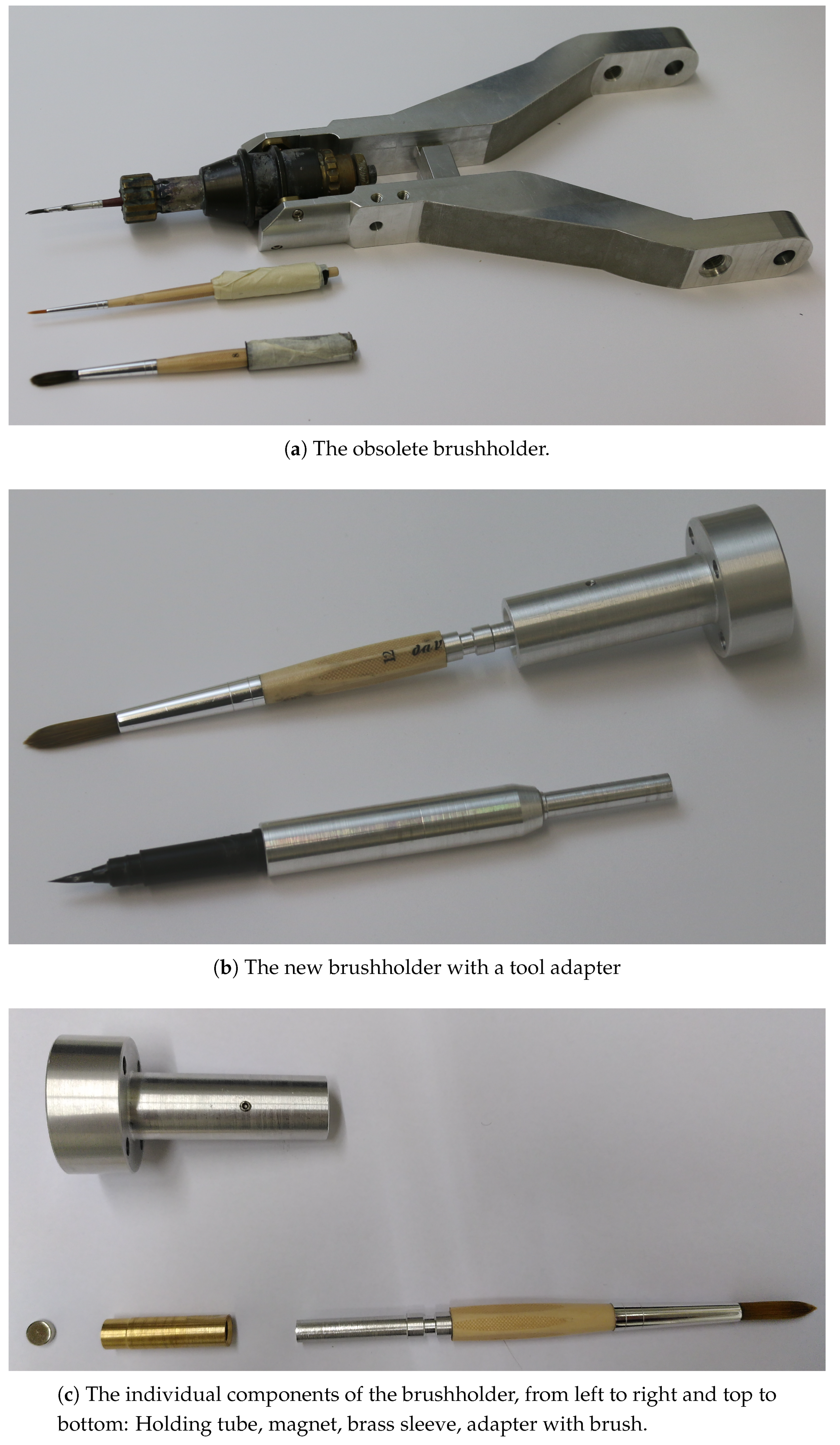
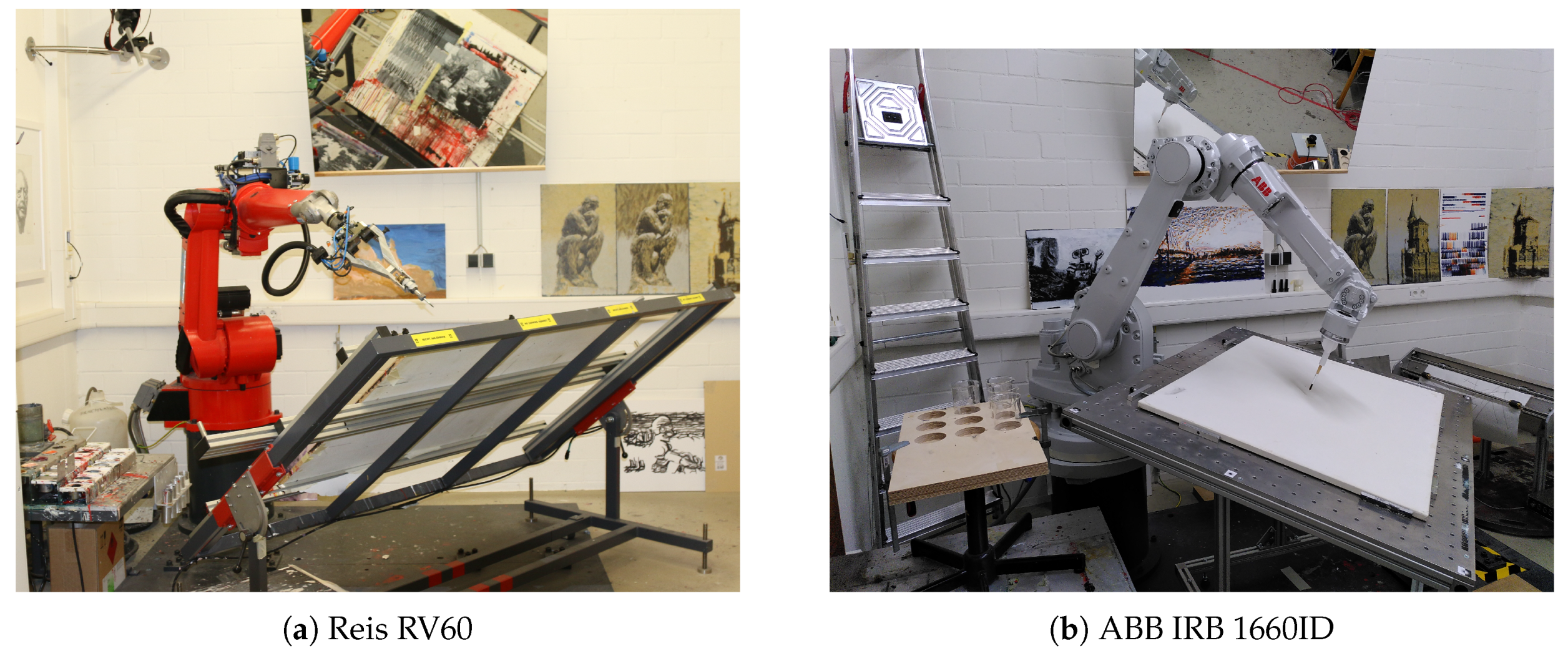
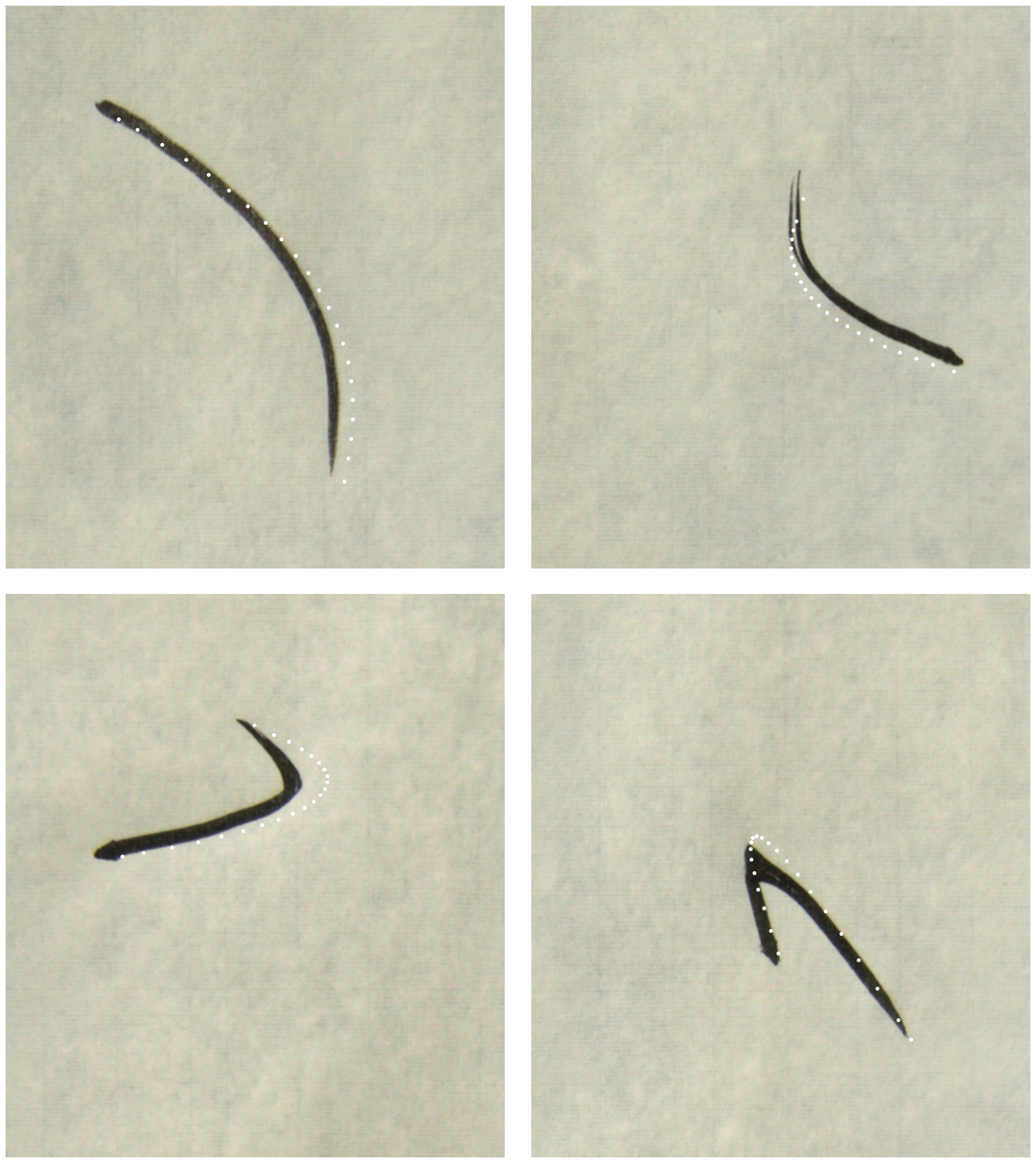
  • Improved Precision: One of the fundamental issues in robotic painting, as it is performed with e-David, is handling its brushes. While the industrial robots used in this project have a repeatability of <±0.02 mm [6,7], the lack of a suitable system to hold brushes rigidly has introduced errors in stroke placement. For example, brushes were wrapped in tape and then stuck into a tube held by the robot. Due to this imprecision the brush tip often deviated from the programmed tool center point (TCP)), had concentricity issues, and tended to slowly drift as the brush was used. By painting along known trajectories, we measured errors up to an amount of 1 mm to 3 mm (see Appendix A). This has been compensated by the painting algorithm, which detected incorrectly placed strokes and attempted to overpaint them in the next pass. However, this approach can lead to artifacts in the produced image due to constant overpainting, as the robot is unable to achieve a required feature on the canvas. Finding a new way to hold a brush rigidly will allow for precise and predictable control of stroke placement on the canvas.
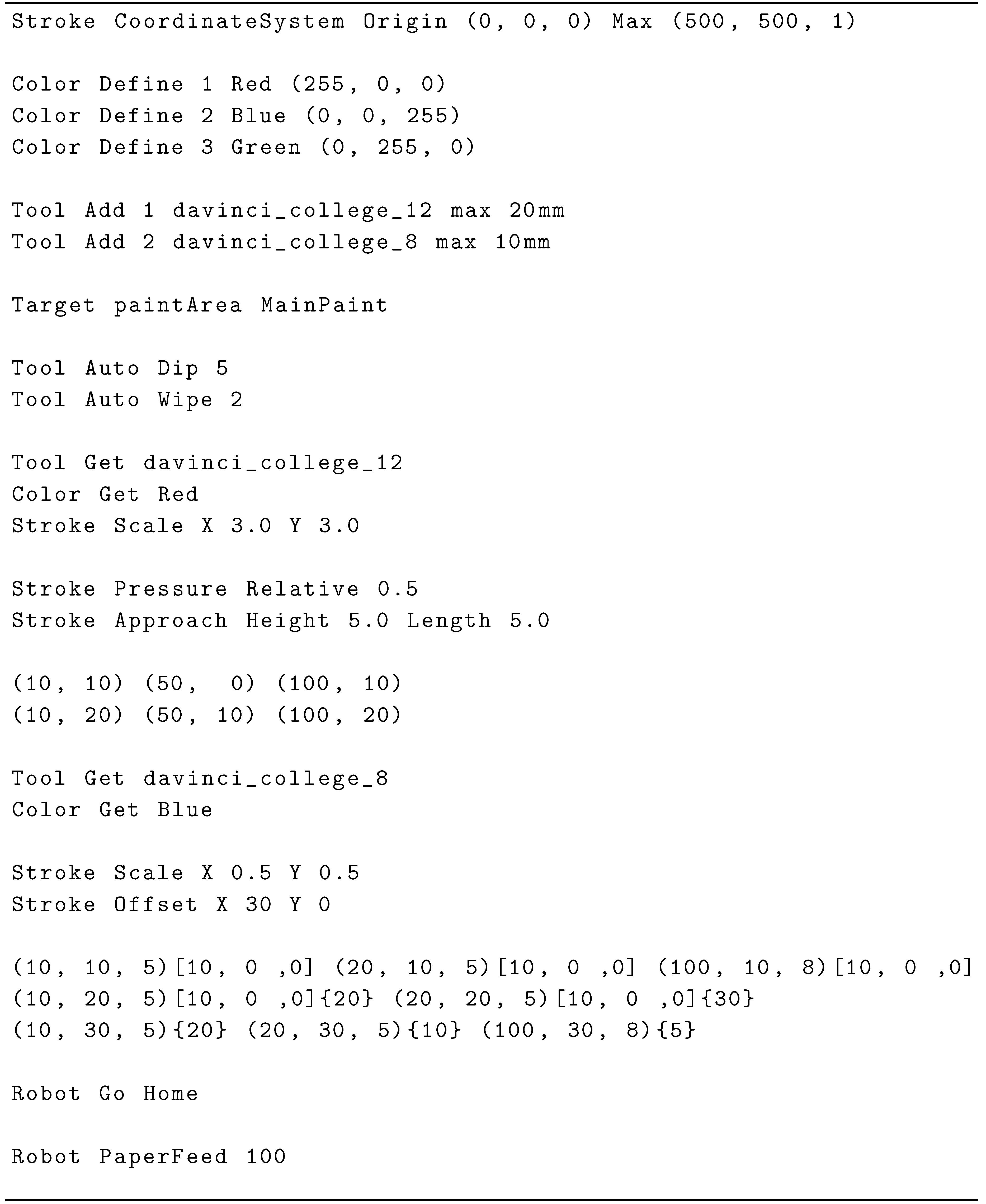
  • Definition of Core Data: The previous software system did not have a rigid formalism to handle stroke data, which created some issues with consistent use of units and reference systems as well as stroke serialization. To remedy this, consistent data structures, which represent the primitives occurring in the painting process and allow the construction of higher-level concepts, should be used. For example, we defined strokes and basic painting actions as primitives. A certain sequence of strokes with a preceding paint pickup command can be combined to a high-level “fill region” command. The same stroke sequence without the pickup command, applied over a previously painted region can be used for a blur effect. Moreover, explicitly associating these commands with units, their reference canvas, and other additional data allows for a more controlled and understandable painting process.
  • Data Recording: Upon attempting to implement first machine learning systems to predict brush behavior, we encountered a lack of training data and the inability to record it in sufficient volume. The painting process previously produced only debug output and canvas feedback pictures, without recording the associated strokes that lead to the observed result. In order to make use of the already acquired knowledge about the used tool or employ more general machine learning approaches, data must be reliably collected and stored in a usable format. This is enabled by having a precise machine with good repeatability and consistent data definitions, as discussed above. Moreover, as painting on a canvas is non-reversible with our current set-up, we had to find a way to provide the robot with a clean canvas for producing strokes. In the old system, this was done by manually exchanging the canvas with a new one. The new system should be able to automatically change to fresh materials and to acquire data by itself for long periods of time. It should be possible to record both single strokes and the results of multiple actions within an entire painting.
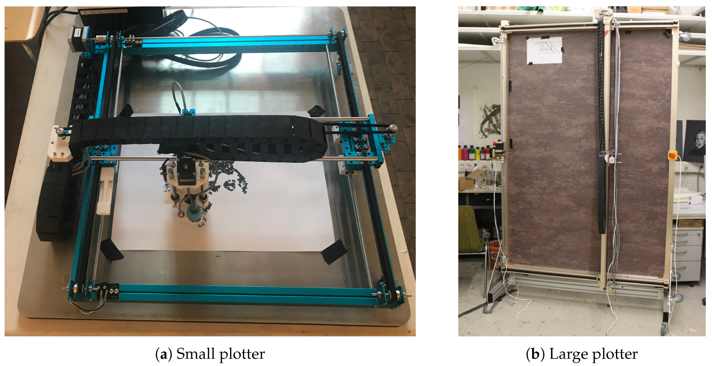
  • Hardware Flexibility: As industrial robots are expensive, difficult to set up, and require experience to operate, e-David should also be usable on much simpler machines. For this purpose, hardware should be mostly abstracted and it should be possible to integrate new machines that are potentially built in the future. One new type of machine already integrated into e-David are XY-plotters. They allow users to work with a subset of e-Davids capabilities and provide a better transition into the project for students working on their thesis in the context of e-David.
  • Open Interfaces: Until now, e-David has only been used at the University of Konstanz. Due to the necessity of using an industrial robot set up very similar to our machine and our tailor-made software, it has been very difficult for others to replicate our results or to reuse them. The new software should allow both simple input of painting commands and a usable output of feedback images. This will make e-David accessible for collaborating researchers, as development done on one painting process will carry over to all other machines in use. New machines are controllable by existing painting processes if a basic driver program is added to the e-David system.
  • Usability for Artists: In the past, a couple of successful collaborations happened with artists, who worked with e-David. This resulted in several exhibitions. However, using the robot was made difficult by very technical interfaces, which are often more suited for development and not optimized for a productive painting workflow. In order to keep the collaborative momentum going, a user-friendly and flexible interface must be created, which allows artists to control the system.
  • Modular Painting Process: The previous e-David software suffered from a monolithic architecture, which structurally included a single painting process. By creating multiple interfaces for painting, several modules could exist in parallel and should be easily exchangeable. The application of separate, specialized painting programs to form a single painting will ideally lead to better results.
  • Machine Learning Groundwork: Through the enhanced data collection methods we plan to build a corpus of brushstrokes, which consist of pairs of trajectories and resulting strokes. Using this dataset we intend to improve upon previous efforts at static stroke analysis [2] and use state-of-the-art machine learning approaches to allow the system to continuously improve its painting abilities on a technique level.
  • Improved Autonomy: Finally, as an extension beyond current machine learning, the robot should be able to investigate unknown aspects of painting autonomously; this, e.g., includes searching the corpus of known strokes for gaps and then running autonomous experiments to close these gaps.

2. Related Work

Apart from e-David, a multitude of other painting machines are currently used in the art world and in research. Historical examples have been discussed extensively in [2], thus in the following we only list contemporary examples.
One of them is Busker, a UR-10-based painting robot under development by Scalera et al. [8] at the University of Udine. They use a collaborative robotic arm that is able to swap between brushes and watercolors. It recreates digital images by using Non-Photorealistic Rendering (NPR) techniques to convert them into strokes. Measurements about watercolor and brush properties are taken into consideration by the NPR methods, which include hatching and gradient-based random strokes [9,10].
Berio et al. [11] use Baxter, a commercially available compliant robot, to replicate a graffiti-style of writing. They use the Sigma-Lognormal model to represent handwriting in segments, which are collected into a motion plan of the entire graffiti. A specialized kinematic model is developed to allow for smooth, compliant robot movement in order to achieve human-like writing motions. Furthermore, they employ an iterative correction scheme, as the fairly relaxed motion control allows inaccuracies to accumulate which must be corrected. Berio et al. [11] results are human-like graffiti, written in thick felt-pen.
Dong et al. [12] propose a method to stylize faces by comparing feature points of an input face to a reference face. They use the offsets of triangularizations of the faces as a difference metric and detect important features of the face from this. They also apply an exaggeration to the most salient features to achieve a caricature-like effect. For painting on their machine, they segment the face into six regions, which are painted in a predetermined order with a SCARA robot holding a pencil. Strokes are placed according to a binarization of the stylized image. However, the results shown by Dong et al. [12] indicate that they do not decompose the image into strokes, but fill in dark regions with a pattern.
Song et al. [13] use a KUKA iiwa 7DoF robot to draw on an arbitrary surface using impedance control. An artist drawing on a tablet provides input strokes, for which the authors describe a method to sample the control points down to an amount usable by the robot. They also discuss how to create triangle strips for rendering a stroke digitally. The core of their paper considers the issue of using the iiwa’s ability for compliant motions to paint on unknown surfaces. For this purpose, the robot obtains initial data about the target surface by probing certain locations with its tool, which allows the computation of a quad-tree height map. During painting, the heightmap is refined as the robot paints over more locations and detects any encountered resistance. Results are shown for paintings on cylindrical surfaces, sections of a sphere, and water containers of irregular shape. The system by Song et al. [13] requires firm pens to be able to sense the underlying surface and cannot use soft brushes.
Xie et al. [14] successfully created a learning system that generates painterly renderings using inverse reinforcement learning. They capture video of humans creating oriental ink paintings and use it to train a learning agent which can then reconstruct the movements of the brush footprint. They use boundary maps to extract shapes from a photograph, which the agent then attempts to fill optimally by generating a sequence of brush movements. Using a renderer, they can convert photographs into ink paintings. The approach by Xie et al. [14] therefore mainly focuses on the creation of realistic single strokes, as opposed to other methods, which focus on filling in an entire painting with many simple strokes.
One such method is provided by Huang et al. [15], who use model-based Deep Reinforcement Learning agents to render images in a painterly style. Their renderer uses Bézier curves of varying thickness, color, and transparency. The renderer is a neural network, which can be run efficiently on a GPU and is differentiable, yielding a significant performance boost according to the authors. It is trained on data collected from a simple software renderer, which can quickly create a large amount of training data. Based on this, they are able to create painterly renderings of many different datasets, consisting of faces and general objects. Their renderings are limited in size by their neural renderer, which outputs 128 px × 128 px images.
Similarly, Jia et al. [16] present a reinforcement learning system that can create more complex curved strokes. Using a staged training process, they create an agent that is capable to place a curved stroke with multiple control points. This gives their agent a continuous action space, which leads to a very large action space. They discuss ways to control this problem, like curriculum learning and difficulty based sampling.
The previously mentioned works show the possibility of training learning agents to produce painterly images. However, in general, no method can be directly transferred to a robotic painting system, which operates in the physical world. For this purpose, these systems will have to be extended to consider the limited palette, real brush dynamics, and the slow rate of feedback, among other factors. Major areas of active research like style transfer [17] have recently shown great advancements. Unfortunately, these have little relation to robotic painting, as they are primarily concerned with the transfer of pixel images to other pixel images. For our research, we would require to extend them to output strokes or develop other techniques that can transfer pixel images to strokes efficiently. As a consequence, we will need to explore which methods are suited for our application, given these limitations. A first attempt is given in Section 3.6.

3. Changes Made to e-David

Based on the identified requirements, we have replaced the old robot arm with new machines. We also redesigned the way the robot holds the brush and some aspects of the painting set-up as a whole. Finally, the camera system was overhauled.

3.1. Robot Replacement

As the old RV60 robot was to be replaced with a more up to date machine, we considered different types of robots. For the general task of moving a paintbrush over a canvas automatically, multiple machine types are applicable. The choice of a certain machine is a trade-off between cost, ease of use, and suitability for the painting task. For painting high precision and a certain level of dexterity (depending on the type of painting desired) are needed. Common industry requirements like high speed, the ability to handle heavy workloads, or easy integration into an industrial network are usually not a necessity.
The first group of machines to consider for painting are cartesian robots, often also referred to as “XY-Plotters” or just “Plotters” in the context of robotic painting. These allow the movement of a tool along the X-, Y-, and Z-axes and have been used for creating drawings for a long time. Plotters can be constructed cheaply and easily in many different sizes, with many parts available off the shelf. These machines are quite safe to use, but without specialized engineering they are unable to angle the tool, perform tool changes, or accomplish other advanced painting tasks.
One of the most common robot types in use in industry is the 6-DoF robotic arm. These are commonly used for machine tending, welding, and spray painting. Such machines have high precision and can position a tool at almost any angle in many positions, allowing for a very human-like painting ability. Handling additional utilities, like a palette or brush cleaning setup is also easy. The major downsides of fully articulated robot arms are their cost and operational safety issues. Furthermore, painting along dynamically generated paths requires a careful setup of the painting surface, as for most industrial robots unexpected singularities cause a non-recoverable machine halt.
Delta robots are 3-DoF or 4-DoF machines, which are commonly used in pick-and-place tasks. Commercially available machines are usually optimized for high-precision and high-speed handling of light objects. Delta robots provide a flat, circular workspace below the main body of the machine with translations of the end effector in the X, Y, and Z direction. Additional axes can be added, like a central rotating axle. This makes their uses comparable to plotters, which are usually more cost-effective in this domain [18]. SCARA robots also fall into this category and also allow rotation around the Z-axis [19]. Delta robots usually cost nearly as much as 6-DoF robot arms and are not a good choice for the use cases encountered in the e-David project.
A final option to consider is cooperative robots or cobots, which have been introduced recently. For example, the KUKA iiwa is a one-arm 7-DoF cobot, designed to work together with humans in varying tasks, for example, assembly. ABB offers the YuMi two-arm 7-DoF system for similar tasks, while also including built-in optical systems for picking up parts [20]. In traditional robotic painting, there is usually no use case for such systems: As humans do not commonly paint collaboratively there seems to be no purpose in implementing such a feature with cobots. Two arm systems are also not a necessity, as it is common in robotics to lay out accessories like the palette or tool cleaning system within reach of the robot and these can be built in such a way that one-arm manipulation is possible. A major drawback of using cobots in painting is that drawing tools are usually pointy and can be dangerous, if the machine happens to accidentally stab a human in the eye or throat area. Such interactions can lead to injury even at slow speeds and with enabled force control. Therefore, using compliant robots for programming strokes by letting a human guide the robot through the motions would require a specially secured setup [21].
The decision ultimately fell on continuing to use 6-DoF arms as primary machines, as these provide the most flexibility for tool handling. An IRB 1660ID and an IRB 1200 by ABB were chosen. These machines come with modern control software and simulations make programming the machine much easier and safer. An appropriate setup of the painting surface helps to avoid singularities. A 6-DoF arm can handle brushes and paint in very flexible ways, allowing us to manipulate many different tools and accessories. This ensures the machine can be adapted to most kinds of painting tasks with relatively low effort. However, the downside of relatively high cost and the need for specialized safety equipment remains. Within our laboratory setting and given the availability of secondary machines, this is acceptable.
To have a secondary platform, XY-Plotters (see Figure 2) were also acquired and modified to fit our needs. These machines are suitable for student projects and to run quick tests, without the need to set robotic arms in motion. These are traditional XY plotters with an additional Z-axis to control tool pressure. One machine can be used as a desktop painter, while the other, due to its size, stands upright. Both are intended to use cartridge-fed ink brushes, but can use a variety of other drawing implements, like sharpies or ball-point pens. The larger plotter can also change between several tools and calibrate the TCP of the current tool.
The plotters have been built as student projects using off-the-shelf hardware for laser cutters and 3D printers, proving that low-cost robotic painting is a possibility. They provide a G-Code control interface via GRBL, an Arduino-based motion controller [22]. Within e-David a general G-Code driver has been implemented which translates stroke commands into G-Code for the plotters. With an appropriate camera set-up, the plotters can be used nearly interchangeably with the robotic arms. The plotters, however, lack the ability to use different colors on the same tool, to clean tools, and to control the brush angle relative to the canvas.
Both plotters have the advantage of not requiring safety equipment, like light curtains or physical barriers, as they pose no threat to human safety. Their main use is for student projects or for test cases where the robotic arms are not required.
Through these new machines, we achieve the goal of flexible hardware in the e-David project. The appropriate machine can be chosen for each painting project, as they can all be controlled interchangeably through the e-David software. The robotic arms can handle a large variety of painting tools and allow us to experiment with many different styles of painting.

3.2. Brush Holder

A major design issue was the construction of an adequate tool holder. The robot should be able to wield a large variety of brushes, from very fine round No. 2 up to larger No. 24 brushes. It should also be possible to integrate brushes that require maintaining a certain orientation, like square brushes. These tools should be held with high precision and should not move under normal painting forces. The design goal for the brush holder was to provide the ability to allow repeatability of ±0.1 mm between strokes.
In the previous system (see Figure 3a), the brush was wrapped in tape and placed into a holding tube, which interfaced with the robot’s pneumatic gripper. The friction between the tape and the tube held the brush in position. Due to the low rigidity of this setup, the brush would deflect by ±2 mm under normal loads. Over time the tape would deform due to the forces applied and other effects like water getting into it. This added a long-term drift of the brush from the TCP up to ±5 mm, which made precise painting very difficult. Furthermore, preparing a new brush was a very messy process, involving many trial fits before an acceptable result was reached.
As brushes are a consumable item, preparing them for use with the robot must be a quick and repeatable operation. However, brushes are not precision-made. They come in shapes which are ergonomic to hold for humans, but challenging for robots. Designing a gripper would be time-consuming and is outside of the scope of our research.
Based on this a prototype holder has been designed and tested (see Figure 3b). We replace most of the structure of the brush with a part that can be precisely held by the machine and that eliminates play from the robot/brush handle interface. The brush is cut to a specified length and center drilled. An aluminum adapter is press-fitted into the hole, so no play is possible. The adapter fits into a brass bushing on the robot end-effector and is held in place using a magnet. Due to the magnetic retention, the holder allows tool changes without the use of pneumatics or other active parts. By avoiding these, we minimize the complexity of the painting set up and increase reliability. Tools are clipped on a holding rack, which engages the groove in the tool adapter. This allows the robot to overcome the magnetic force and pick up another tool.
We have measured a final tolerance of ±0.05 mm at the brush ferrule, indicating that the setup is rigid. As the metal parts do not bend during normal operations, no long-term tool deflection has to be considered, aside from the actual bristles deforming. The entire holder can be seen in Figure 3.
The second iteration of the holder will use a non-self-locking tapered adapter. Using tapers for tool holding is common in machining [23] and will make tool changings more reliable. A cross section of the next design can be seen in Figure 4.
Through the upgrade of the brush holder, we partially achieve the goal of improved precision in stroke placement. Now that the brush is held with minimum play, the flexible bristles of the brush remain as an element which is difficult to control. During painting we observed that brushes deform gradually, i.e., their tips move off the center axis of the brush. Robotic systems are traditionally modeled to consist of rigid bodies, called links, with moving joints between them [24]. As a consequence, in most robotic arm systems the TCP is also assumed to be rigidly attached to the last link [25]. For robotic painting, we use the brush tip as the TCP. However, the compliant tool exhibits both temporary and longer lasting deformation, which must be considered.
Data on brush deformation is hard to find. Publications about approximating the physics of brushes do exist, which focus on simulating painterly effects in digital painting [26,27,28]. These systems do not allow parametrization for a physical brush or consider long term bending of the bristles. While one such publication exists about circular steel brushes [29], data on paintbrushes with polymer or natural fibers is not available. We show a table of measurements in Appendix A.
Our measurements have shown that the round brushes used for e-David deform after just ten seconds of application when wet. The deflection of 1 mm to nearly 3 mm is significant in painting, as an error of this size can blur sharp corners or destroy small features. Now that the uncertainty about the tool’s location has been restricted to the bristles, we are able to employ other methods to achieve even better precision. These are building a database of known stroke results (see Section 3.3) and applying machine learning to predict stroke results from bristle behaviour (see Section 3.6).

3.3. Painting Hardware Improvements

Data recording has been made possible through an automatic paper feed and the use of the existing optical feedback mechanism. The paper feed is an extension of the previous canvas and is currently only available for the IRB 1200. A paper roll is attached at the bottom of the canvas and can spin freely on an axle. The paper is pulled over the canvas by a roller mechanism at the top of the canvas which is powered by a stepper motor. The stepper motor is controlled through GRBL G-Code, which allows for the plotter driver to be reused. At the bottom of the canvas an additional spring-loaded paper brake has been added to keep the paper slightly tensioned over the canvas. Care must be taken not to wet the paper too much, as this will result in tearing. Taking this into account, the robot can continuously paint over up to 100 m of paper. The paper feed can be seen in Figure 5.
Using this mechanism it is possible to generate strokes, paint them on the paper, and then use the camera to capture the results. As the canvas size is known, we are able to measure the differences between the intended trajectory and the realized stroke, as can be seen in Figure 6.
The recording process has been very reliable so far and several hundred strokes can be recorded in one go. One page of 20 strokes can be painted in 5 min, giving a rate of 4 strokes per minute. By optimizing painting speed further, we intend to double this rate to 8 strokes per minute, which would allow us to capture 5760 strokes in 12 h. Within one or two weeks this set-up could provide a suitably large data set for most machine learning approaches.The dataset can also be used as a stroke database. A desired stroke can be searched in it, and the corresponding movement can be executed. If a feature similar to one of these strokes is required in a painting, the stroke can be reliably be reproduced by executing the stored corresponding brush movement.
The following minor alterations have been made. These engineering considerations do not directly relate to the main objectives stated previously but are relevant for the replication of our set-up.
  • The containers for the painting fluids used to be made from steel. As these were very difficult to clean and replace in case of loss, standard glass containers are now used.
  • The holder for the paint containers, the palette, used to be a steel construction with Teflon lining and complex geometry to accommodate lids for the containers. This has been replaced with a flat wooden board with holes in it, to make palette layout more flexible. Furthermore, despite the Teflon, the lids tended to accumulate old paint and became unreliable. This resulted in at least one major crash. The wooden boards can be easily replaced when too much old paint accumulates. We have also determined that there is no need for robot-operable lids on the paint containers, as the regular stirring is sufficient to keep them from drying out.
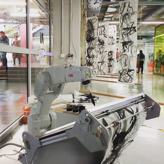
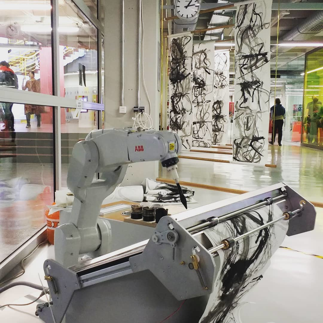
  • Previously, the robot was placed in front of the canvas, which made it occlude the painting result for the camera. A feedback picture was only taken once every 300 to 1000 strokes, to speed up painting. We have reoriented the table, so that it now slopes away from the machine and the arm has to reach over to paint on the surface. This allows the camera to be placed on the opposite side, granting it a clear view of the canvas, whenever the robot picks up new paint. As this usually happens every 5–10 strokes, feedback frequency can be increased significantly.
Overall, while new features were introduced, an emphasis has been put on simplification of the design: Previously overengineered solutions made actual painting and maintenance difficult.

3.4. Camera System Rework

The camera system is a major component of e-David, and the ability to use visual feedback in the painting process is one of the main research points. Now that the executing side of the painting process has been improved, the next step is upgrading the camera system to be more performant.
The previous camera system consisted of a Canon EOS 5D Mark II fixed to a wall mount for the larger e-David robot or a Canon EOS 50D mounted on a tripod for the small portable e-David. It was placed behind the robot facing the canvas. As a consequence, the robot was always positioned between the canvas and the camera, requiring a move to a special “hide pose” for each feedback picture. By repositioning the canvas so the robot is painting from behind, the camera can acquire an unobscured feedback picture whenever the robot moves out of frame to pick up paint. This increases the rate of feedback pictures significantly as the robot does not need to reposition. In addition to the change of the mounting position, the camera was upgraded to a Canon EOS 6D Mark II, which offers a slightly higher resolution of 26.2 megapixels. On the 1200 mm wide canvas, the feedback pictures with a resolution of 6240 px × 4160 px yield approximately 5 pixels per millimeter, allowing the feedback mechanism to discern features down to 0.2 mm. Besides the hardware changes the software module controlling the camera is undergoing a major renewal.
In the past it was cumbersome to calibrate the canvas to perform a camera calibration. Positions of reference points in the image had to be marked by hand to correctly perform an extrinsic camera calibration and to obtain an undistorted image of the canvas. The calibration was only done once after the camera was set up. This was especially problematic for portable installation with the small robot, where the tripod could be easily slightly moved by accident which would lead to an invalid camera calibration.
To prevent those issues the new camera module will use ChArUco markers provided by the Open Source Computer Vision framework OpenCV. These markers are permanently attached to the painting surface on which the canvas is positioned. Because the relative position of the robot to its painting surface is fixed, the marker positions only have to be measured once. ChArUco are a combination of a chessboard pattern together with ArUco markers. This combination provides the resilience against partial occlusion of some markers of an ArUco board coupled with the accurate corner detection of chessboard patterns [30]. Due to the use of easily detectable markers, we will be able to take a new feedback image and perform a camera calibration more frequently to prevent misaligned feedback images caused by small camera movements. In the previous camera system, the color calibration was performed only once and the system relied on lighting conditions to be constant. With the new camera system, we will equip the color calibration board with ArUco markers in order to detect it automatically. Thus, it is possible to perform a new color calibration for each feedback image to compensate for changes in the lighting of the canvas.
Currently we are only able to take feedback images of the canvas when the robot is fully out of the view of the camera. These situations occur when the robot picks up new paint or is intentionally moved out of frame. This increases the necessary movements of the robot and therefore the time to complete a painting drastically. In the future we plan to combine multiple consecutive feedback images and only include the part of the canvas that was changed by the last brushstroke. This robot aware feedback image could highly reduce the needed robot movements and allow for stroke-by-stroke feedback.

3.5. Painting Software Improvements

One of the first software improvements made was the precise Definition of Core Data. The data structures used in e-David must facilitate simple painting operations, while also accurately modeling the state of the machine, to allow safe operation. For example, a safety mechanism is in place which stops the execution of commands which would crash the tool or contaminate a paint container.
The stroke is the basic primitive of painting operations. It describes a single tool movement and associated state. It includes the following.
  • The required brush
  • The paint used for the stroke
  • The associated canvas object
  • Approach and departure mode, which defines the angle at which the stroke is placed onto or removed from the painting surface
  • The stroke trajectory given as a sequence of XYZ coordinates, in millimeters relative to the associated canvas object
Before any given stroke is executed, the driver can ensure tool or paint changing occurs so the desired stroke can be painted. Keeping track of the machine state is required to avoid common user errors.
By enforcing all strokes to be given in millimeters, they are kept separate from the camera and painting modules, which usually operate on a virtual canvas that uses pixels to reference points on it. An explicit conversion from pixel space to millimeter space must be performed, based on the known size of the target canvas. At this interface we can also use known data about stroke width and its relation to brush pressure (see [2]) to compute the required brush pressure for a required stroke width.
Besides strokes, e-David uses more general paint commands, which trigger other actions, like brush cleaning, tool changes, or dipping the brush into paint. Several paint commands can be bundled into higher-level actions, which represent more complex painting actions, like filling in regions or applying a certain blurring technique with a brush only dipped into water.
Building on these generalized paint commands, e-David can be externally controlled via a simple command language, through which the project exposes an open interface for others. Commands can be passed through a text file which is parsed line by line or sent through a socket. Received painting commands are logged, so a painting process may be resumed when it is interrupted. An example of the command language can be seen in Listing 1. The language is human-readable and adapted to the stateful nature of painting machines: After a brush has been picked up and dipped into paint it follows that subsequent strokes are executed in that color. Many actions can be set to an automatic mode, like re-wetting the brush after n strokes. Using a default configuration, the robot can be immediately used for painting, without requiring a lot of configuration overhead by the painting program.
Feedback pictures of the canvas are provided by e-David by placing them into a folder, which can be accessed locally or though FTP. We found this to be the most simple approach to implement, which also provides a log of steps “for free”. This data can be used to regain the painting state after a shutdown and to build a database that relates stroke commands to the results. Furthermore, avoiding an explicit connection reduces dependencies. Previous work with “Cap’n Proto” [31], a protobuf implementation, turned out to be overly complex: The painting process does not need high speed or memory-efficient tools, as the machine is the limiting factor when it comes to the speed of painting. Moreover, debugging is much easier, as a user can simply drop in files to use the system.
We have implemented several small painting programs in Python and Processing, which use these interfaces to generate images. Thus we show that the new core system allows for modular painting processes.
The modularization also gives us improved usability for artists: They can use familiar programming environments or a graphical user interface, exposing only a part of the system, can be implemented. Experience has shown that a general UI is difficult to implement without overwhelming the user. Instead it seems practical to build smaller, custom tools for a certain goal, as specified by the artist.
Listing 1. e-David command language.
Applsci 10 03396 g009

3.6. Machine Learning Groundwork

A multitude of previous works exists about digitally simulating brush strokes. However, even advanced models like that of Baxter et al., where brushes are simulated based on measurements of real brushes, do not allow for a brush simulation which predicts all aspects of a real brush [27]. Xie et al. use reinforcement learning in order to learn how to produce digital stroke paintings based on stroke samples provided by calligraphers [5,14]. The system is then able to output trajectories that are rendered to ink drawings.
Using e-David we are able to generate large samples of strokes and have fine control over their execution. Using the data collection mechanisms described previously we are working on designing a learning agent that can be pre-trained on a simulation and then use the robot for a final refinement by learning brush behavior on the physical machine. By creating methods for autonomous acquisition of data, we also reach the required improved autonomy.

4. Applications

The upgrades to e-David discussed here enable three advancements: Easier development of painting programs, the ability to bring the e-David out of the lab and allow other people to see the results, and the creation of a hardware and software foundation for future experiments in robotic painting.

4.1. Work with Artists

In reworking e-David we have made it easier for artists to work with robotic painting. Usually the required technical skill is a major barrier to entry. Further, integrating the artist’s ideas into the system can be problematic if it is not sufficiently generalized. We collaborated on art projects multiple times with the artist Liat Grayver (https://www.liatgrayver.com/projects-and-exhibitions), who used the robot in a modern art context to explore the new possibilities provided by these machines. In the process, we observed shortcomings of the old system w.r.t. quick experimentation and ease of control without a strong technical background. Especially, a large number of preparatory steps and the need to integrate new painting processes into the e-David software itself posed problems.
With the new system an artist can easily input strokes manually in order to develop an understanding of the operation of the machine. Then they can create their own stroke generators in a familiar environment like processing or other graphical programming environments. By outputting the standardized stroke format and waiting for an image file to be created as feedback, a basic feedback loop is achievable. While the task of writing a program to actually generate a work still lies with the artist, we have abstracted most control tasks related to the operation of the robot away. The artists can focus on the image.
We aim for two uses of e-David: The system shall be used for autonomous painting as well as being a tool for human artists. Both types of application benefit from each other, as the required machine capabilities are similar and one approach can provide new input for the other.

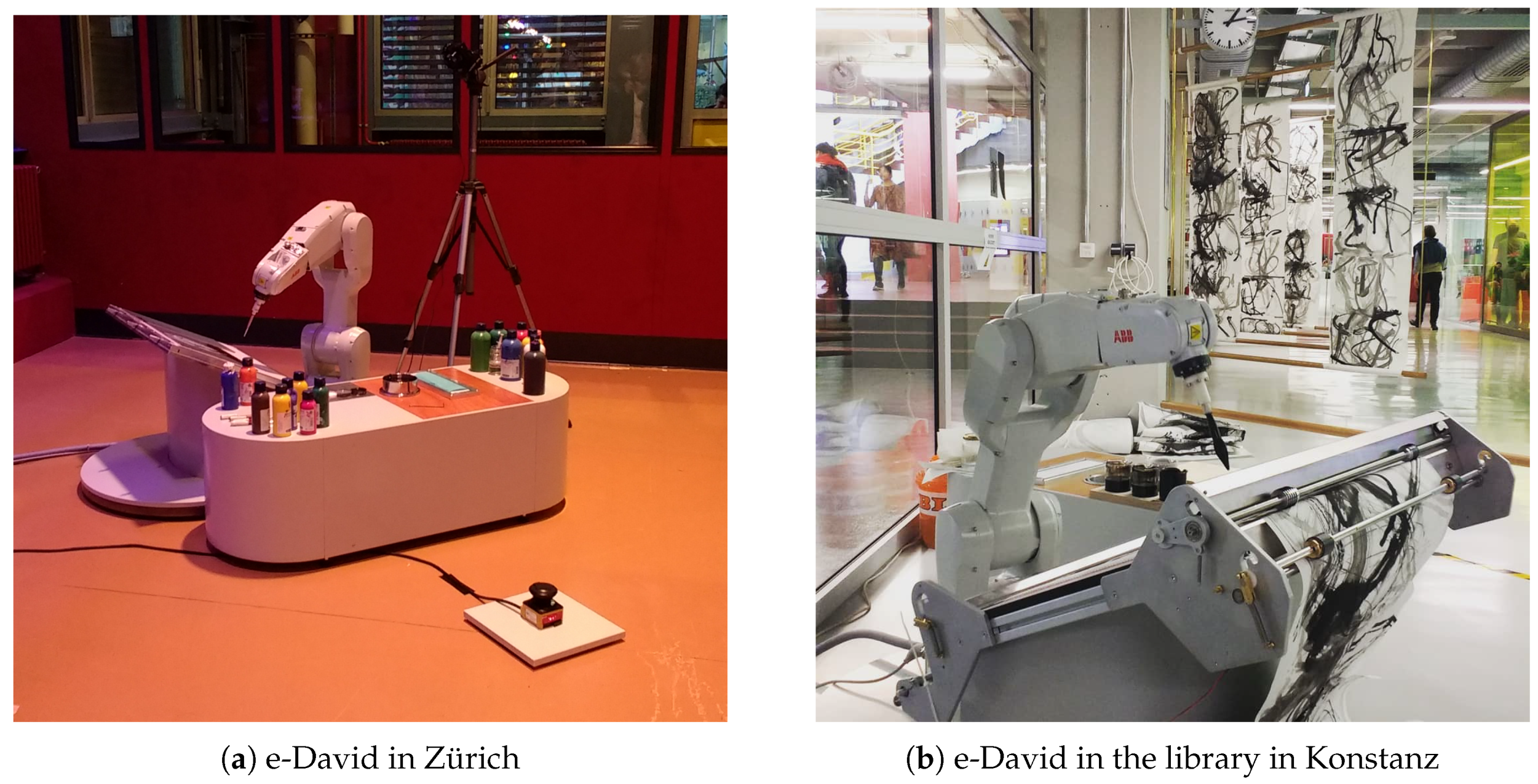
4.2. e-David Exhibitions

A painting robot is often an object of public interest, as the task performed is relevant and relatable for most people. As such, presenting robotic painting outside of the lab in the context of public exhibitions is an option. The issues preventing this are the difficulty of transporting the machine to the venue and providing a safe painting show. This has been achieved twice with the IRB 1200—once in Zürich for three days and in another three-week exhibition at the University of Konstanz—as shown in Figure 7.
Access to the robot must be regulated according to the EU directive on machinery for the safety of the visitors and operating personnel [32]. For a good painting result, lighting must be controllable, as the optical feedback system will be degraded otherwise. Public feedback to the machine painting has been positive, allowing us to pursue further exhibitions in the future.

5. First Steps towards Deep Learning in the e-David Project

The improvements made to the hardware and software of e-David now provide a foundation to experiment with machine learning in the context of robotic painting. The goal is to create agents that can help with certain aspects of the painting process, like brush dynamics or paint interactions. Later, more general tasks like image composition can be considered. Here, we show an application of the known pix2pix model by Isola et al. [33] as a first attempt in the domain of brush dynamics.
As a first task, we considered the rendering of brushstrokes from known brush trajectories. This is a non-trivial task as the appearance of the stroke is highly determined by the physical brush dynamics. As part of a lecture, a student group investigated in cooperation with the e-David project team the possibility to generate rendered brushstrokes by capturing the brush-dynamics with a deep learning method. The students used the small plotter shown in Figure 2.

5.1. Data Generation and Data Gathering

To be able to learn how to generate strokes given the trajectories, at first a data set of known trajectories and the corresponding ink brush painted strokes was created. Smooth trajectories were generated by placing B-splines with four control-points randomly on a 256 px by 256 px canvas. In addition to the simple spline, the direction of the trajectory was encoded of the RGB color components of the images as shown in Figure 8c. It is crucial for the learning of the brush strokes to align the rendered trajectories precisely to ink brush strokes. Therefore, the trajectories are drawn with the ink-brush on a DIN A3 paper with ArUco markers printed on it (see Figure 8a). These makers fulfill two purposes: First, they encode an ID to identify and associate the paper to the trajectories drawn on it, and second, they are used to compensate for a slight misalignment of the paper during scanning. To compensate for a misalignment of the paper while drawing the splines, the plotter draws circles in the empty squares shown in Figure 8b. These circles are used to perform a final alignment of the drawn trajectories to the artificially rendered ones. In Figure 8b, the 5 × 6 grid of randomly generated strokes can also be seen.

5.2. Deep Learning Model

The model is based on a Generative Adversarial Net (GAN) proposed by Goodfellow et al. in [34]. GANs are supposed to generate images that are indistinguishable from a given ground truth data set. To fulfill this task, they consist of two Convolutional Neural Networks (CNN), the generator with the goal to produce images that cannot be distinguished from the ground truth data set by the discriminator. These two networks contest each other by producing images that are as convincing possible and by telling the generated images apart from real ones. Afterwards, the generator can be used alone, to produce images from a random latent space vector, that are also similar to the ones given in the ground-truth dataset. Beyond this, we want to generate images that are not only similar to those in the ground-truth data set but also contain the additional information of the trajectory. This can be accomplished by the extension of GANs to conditional generative adversarial nets (cGANs) introduced by Mirza et al. in [35]. In this approach, not only the ground-truth image is provided to the generator and discriminator, but additionally also another image, the condition, is fed to both networks. To generate the results shown in Figure 8d, the widely used pix2pix model introduced by Isola et al. [33] was employed.

5.3. Deep Learning Results

Figure 8d shows an exemplary output of the pix2pix model after training epoch 197. The first row contains the condition the model was provided with and the last row contains the original scanned image. In the middle are the results produced by the model shown. The model was able to learn to convert simple trajectories to images of strokes. These generated strokes have a similar width to the original ones. Some realisitc artifacts are also discernable in the generated strokes, like blobs at the end of the stroke or small white patches inside the stroke. These are normally generated by bristles splitting up and show how some realistic features are picked up by this model.

5.4. Future Plans

The learning experiment shows that with a simple model we can already predict stroke outcomes from trajectories. We plan to reverse this by looking into the possibility of training a model which can predict the trajectory required to achieve a certain stroke. The long-term goal is to train an agent which is capable to determine suitable painting actions given a target image and a feedback image of the current canvas state. Reinforcement learning appears to be the method of choice, as the agents can directly produce painting actions and previous work for digital painting exists [5,14]. The space of possible single strokes is extremely large and the machines are slow to realize them on the canvas and record them. Therefore, methods to direct the learning agent to actions which yields as much new information as possible must be considered, like reverse curriculum learning [36] or curiosity-driven learning [37].
Another possible approach is to apply pre-trained systems on a more abstract level of the painting process. For example, existing general object detectors, like Mask R-CNN [38], could help to gather semantic information within an image and use it to realize it on the canvas with a specialized painting algorithm. Similarly, specialized networks like VGG-face [39] could be used to identify faces or features of a face, and mark them for special treatment. In doing so, we avoid “relearning” already implemented basic features and can take first steps towards artificial creativity.

6. Conclusions

The overhaul of the e-David system has led to a more general framework for the operation of painting machines. A simple approach to hardware design, coupled with very precise machines enables productive and safe operations. The modularized and simplified painting set-up made the system more approachable and robust. We upgraded the painting machines in several ways. The new set-up is able to do more precise painting due to new tooling and is easier to maintain. The updated software is more modular, which facilitates experimentation and collaboration. Our upgrades were based on experience with the initial robotic setup and the knowledge obtained is generalizable to other painting machines.
Our main contribution is the development of a platform that allows the collection of data about physical painting processes. We bridge the gap between learning systems for painterly rendering in software and the physical world. For this we also suggest machine learning approaches which can adapt to machine-based painting.

Future Work

After working on the foundations of the painting system we will focus on the implementation of painting programs and image production. The goal is to have a variety of different programs to generate new works, ranging from simple black and white ink drawings, to more complex, colored paintings. We intend to build multiple specialized generators, which are optimized for specific tasks, such as portraiture or the representation of a certain complex object. Later, these individual generators can be chained such that a composite painting is created. For example, programs each specializing in trees, clouds, and mountains could create a landscape painting. Ideally, this will provide better results than an object-agnostic system could.
Remarks: No examples of new paintings can be provided at the time of writing, as machine access is not possible due to the COVID-19 shutdown.

Author Contributions

Methodology, software, investigation, and writing—original draft preparation: J.M.G. and P.P.; writing—review and editing, supervision, project administration, and resources: O.D. All authors have read and agreed to the published version of the manuscript.

Funding

This research received no external funding.

Acknowledgments

We thank Jonas Körner for his work on the XY-Plotters and the G-Code driver. Additionally, we thank Timon Kilian, Jonas Körner, and Patrick Paetzold for providing the results of their lecture report on rendering ink-brush strokes using GANs.

Conflicts of Interest

The authors declare no conflicts of interest.

Abbreviations

The following abbreviations are used in this manuscript:
DoFDegree of Freedom
TCPTool Center Point
ArUcoLibrary for marker detection developed by the Ava gRoup of the University of Cordoba [40,41]
ChArUcoChessboard + ArUco Marker
GRBLProject name of an Arduino based G-Code Parser (https://github.com/gnea/grbl)
CNNConvolutional Neural Network
GANGenerative Adversarial Network
cGANConditional Generative Adversarial Nets

Appendix A. Brush Deflection Data

In order to determine how much a paintbrush might deflect during painting, a test was performed with the robot. We used “Davinci College” brand brushes with nylon bristles in the sizes 2, 4, 8, and 12. Table A1 lists the brushes used, the width of the brush, as well as the bristle length from the ferrule to the tip. The experiment consists of pressing the brushes against the rigid painting surface so that the bristles bend. After retracting the brush, the bristles remain slightly bent, which is relevant for the painting process. We measure the bend as deviation in millimeters from the brush’s center axis. A sketch of this can be seen in Figure A1a.
The brushes were wetted in water and mounted to the robot. The robot was programmed to hold the brush perpendicular to the painting surface and approach it at a 45° angle, until the brush tip touched the painting surface. Then, the robot continued to move along the trajectory for a further 75% of the bristle length of the current brush, called the application distance. This caused the brush to bend in one direction. After ten seconds, the robot moved in reverse and the measurement was taken. We measured the deflection of the brush tip from the main axis using calipers. For each brush type we tested five specimens two times each. The measurement results can be seen in Table A1.
The data shows that all employed brushes deflect during painting and that the tips stay off-center between approximately 1 mm and 2 mm. This shows that to achieve precise stroke placement, tool deflection must be considered.
Table A1. Types of brush.
Brush TypeWidth (mm)Bristle Length (mm)Application Distance (mm)
Davinci College 21.5107.5
Davinci College 431410.5
Davinci College 8522.516.9
Davinci College 125.52619.5
Figure A1. Brush deflection.
Applsci 10 03396 g0a1

References

  1. Reis Roboter-Baureihe RV Technische Daten; Reis Robotics GmbH: Obernburg, Bavaria, Germany, 2012.
  2. Gülzow, J.; Grayver, L.; Deussen, O. Self-improving robotic brushstroke replication. Arts 2018, 7, 84. [Google Scholar] [CrossRef] [Green Version]
  3. Hertzmann, A. Painterly rendering with curved brush strokes of multiple sizes. In Proceedings of the 25th Annual Conference on Computer Graphics and Interactive Techniques, Orlando, FL, USA, 19–24 July 1998; pp. 453–460. [Google Scholar]
  4. Levine, S.; Pastor, P.; Krizhevsky, A.; Ibarz, J.; Quillen, D. Learning hand-eye coordination for robotic grasping with deep learning and large-scale data collection. Int. J. Robot. Res. 2018, 37, 421–436. [Google Scholar] [CrossRef]
  5. Xie, N.; Hachiya, H.; Sugiyama, M. Artist agent: A reinforcement learning approach to automatic stroke generation in oriental ink painting. IEICE Trans. Inf. Syst. 2013, 96, 1134–1144. [Google Scholar] [CrossRef] [Green Version]
  6. Product Specification IRB 1200. ABB Document ID 3HAC046982. 2017. Available online: https://library.e.abb.com/public/695d95569cdc46b5a2722f7d1efacb1d/3HAC046982%20PS%20IRB%201200-de.pdf (accessed on 9 November 2019).
  7. Product Specification IRB 1660ID. ABB Document ID 3HAC023604. 2017. Available online: https://library.e.abb.com/public/f021934fe70f41e9872b10d833d9ed54/3HAC023604%20PS%20IRB%201600-de.pdf (accessed on 12 January 2020).
  8. Scalera, L.; Seriani, S.; Gasparetto, A.; Gallina, P. Non-photorealistic rendering techniques for artistic robotic painting. Robotics 2019, 8, 10. [Google Scholar] [CrossRef] [Green Version]
  9. Scalera, L.; Seriani, S.; Gasparetto, A.; Gallina, P. Watercolour robotic painting: A novel automatic system for artistic rendering. J. Intell. Robot. Syst. 2018, 95, 871–886. [Google Scholar] [CrossRef]
  10. Scalera, L.; Seriani, S.; Gasparetto, A.; Gallina, P. Busker robot: A robotic painting system for rendering images into watercolour artworks. In IFToMM Symposium on Mechanism Design for Robotics; Springer: Cham, Switzerland, 2018; pp. 1–8. [Google Scholar]
  11. Berio, D.; Calinon, S.; Leymarie, F.F. Learning dynamic graffiti strokes with a compliant robot. In Proceedings of the 2016 IEEE/RSJ International Conference on Intelligent Robots and Systems (IROS), Daejeon, Korea, 9–14 October 2016; pp. 3981–3986. [Google Scholar]
  12. Dong, X.L.; Li, W.J.; Xin, N.; Zhang, L.P.; Lu, Y.X. Stylized Portrait Generation and Intelligent Drawing of Portrait Rendering Robot. DEStech Trans. Eng. Technol. Res. 2018. [Google Scholar] [CrossRef] [Green Version]
  13. Song, D.; Lee, T.; Kim, Y.J. Artistic pen drawing on an arbitrary surface using an impedance-controlled robot. In Proceedings of the 2018 IEEE International Conference on Robotics and Automation (ICRA), Brisbane, Australia, 21–25 May 2018; pp. 4085–4090. [Google Scholar]
  14. Xie, N.; Zhao, T.; Tian, F.; Zhang, X.H.; Sugiyama, M. Stroke-based stylization learning and rendering with inverse reinforcement learning. In Proceedings of the Twenty-Fourth International Joint Conference on Artificial Intelligence, Buenos Aires, Argentina, 25–31 July 2015. [Google Scholar]
  15. Huang, Z.; Heng, W.; Zhou, S. Learning to paint with model-based deep reinforcement learning. In Proceedings of the IEEE International Conference on Computer Vision, Seoul, Korea, 27 October–2 November 2019; pp. 8709–8718. [Google Scholar]
  16. Jia, B.; Fang, C.; Brandt, J.; Kim, B.; Manocha, D. Paintbot: A reinforcement learning approach for natural media painting. arXiv 2019, arXiv:1904.02201. [Google Scholar]
  17. Gatys, L.A.; Ecker, A.S.; Bethge, M. A neural algorithm of artistic style. arXiv 2015, arXiv:1508.06576. [Google Scholar] [CrossRef]
  18. CLAVEL, R. Robots Parallèles: Du Packaging à Cadence élevée à la Production D’ultra Haute Précision. 2011. Available online: http://jnrr2011.irccyn.ec-nantes.fr/presentations/ReymondClavel.pdf (accessed on 19 February 2020).
  19. Das, M.T.; Dülger, L.C. Mathematical modelling, simulation and experimental verification of a scara robot. Simul. Model. Pract. Theory 2005, 13, 257–271. [Google Scholar] [CrossRef]
  20. Product Specification IRB 14000 YuMi. ABB Document ID 3HAC052982. 2018. Available online: https://library.e.abb.com/public/5056ab1df62c47f7ae78cc5c1218533c/3HAC052982%20PS%20IRB%2014000-de.pdf (accessed on 12 January 2020).
  21. Neunte Verordnung zum Produktsicherheitsgesetz (9. ProdSV). BGBl. I S. 2178, 2202. 2011. Available online: https://www.gesetze-im-internet.de/gsgv_9/9._ProdSV.pdf (accessed on 7 February 2020).
  22. Sungeun, K.J. GRBL Project Repository. 2020. Available online: https://github.com/grbl/grbl (accessed on 18 February 2020).
  23. Weck, M. Werkzeugmaschinen 2: Konstruktion und Berechnung; Springer: Cham, Switzerland, 2006. [Google Scholar]
  24. Lynch, K.M.; Park, F.C. Modern Robotics; Cambridge University Press: Cambridge, UK, 2017. [Google Scholar]
  25. Operating Manual: IRC5 with FlexPendant for RobotWare 6.05. ABB Document ID 3HAC050941. 2017. Available online: https://library.e.abb.com/public/eb165ae225d9e01fc1257c0c003bbe3a/3HAC041344-de.pdf (accessed on 14 December 2019).
  26. Chu, N.H.; Tai, C.L. An efficient brush model for physically-based 3D painting. In Proceedings of the 10th Pacific Conference on Computer Graphics and Applications, Beijing, China, 9–11 October 2002; pp. 413–421. [Google Scholar]
  27. Baxter, W.; Govindaraju, N. Simple data-driven modeling of brushes. In Proceedings of the 2010 ACM SIGGRAPH Symposium on Interactive 3D Graphics and Games, Washington, DC, USA, 19–21 February 2010; pp. 135–142. [Google Scholar]
  28. Baxter, W.V.; Lin, M.C. A versatile interactive 3D brush model. In Proceedings of the 12th Pacific Conference on Computer Graphics and Applications, PG 2004, Seoul, Korea, 6–8 October 2004; pp. 319–328. [Google Scholar]
  29. Stango, R.; Heinrich, S.; Shia, C. Analysis of constrained filament deformation and stiffness properties of brushes. J. Eng. Ind. 1989, 111, 238–243. [Google Scholar] [CrossRef]
  30. Detection of ChArUco Corners. Available online: https://docs.opencv.org/4.2.0/df/d4a/tutorial_charuco_detection.html (accessed on 28 January 2020).
  31. Varda, K. Cap’n Proto. 2015. Available online: Https://capnproto.org (accessed on 25 November 2019).
  32. European Parliament. Directive 2006/42/EC of the European Parliament and of the Council of 17 May 2006. Off. J. Eur. Union 2006. Available online: http://data.europa.eu/eli/dir/2006/42/oj (accessed on 9 June 2006).
  33. Isola, P.; Zhu, J.; Zhou, T.; Efros, A.A. Image-to-Image Translation with Conditional Adversarial Networks. arXiv 2016, arXiv:1611.07004. [Google Scholar]
  34. Goodfellow, I.; Pouget-Abadie, J.; Mirza, M.; Xu, B.; Warde-Farley, D.; Ozair, S.; Courville, A.; Bengio, Y. Generative adversarial nets. In Advances in Neural Information Processing Systems; NIPS: Montréal, QC, Canada, 2014; pp. 2672–2680. [Google Scholar]
  35. Mirza, M.; Osindero, S. Conditional generative adversarial nets. arXiv 2014, arXiv:1411.1784. [Google Scholar]
  36. Florensa, C.; Held, D.; Wulfmeier, M.; Zhang, M.; Abbeel, P. Reverse curriculum generation for reinforcement learning. arXiv 2017, arXiv:1707.05300. [Google Scholar]
  37. Still, S.; Precup, D. An information-theoretic approach to curiosity-driven reinforcement learning. Theory Biosci. 2012, 131, 139–148. [Google Scholar] [CrossRef] [PubMed]
  38. Abdulla, W. Mask R-CNN for Object Detection and Instance Segmentation on Keras and TensorFlow. 2017. Available online: https://github.com/matterport/Mask_RCNN (accessed on 1 January 2020).
  39. Parkhi, O.M.; Vedaldi, A.; Zisserman, A. Deep face recognition. 2015. Available online: https://ora.ox.ac.uk/objects/uuid:a5f2e93f-2768-45bb-8508-74747f85cad1 (accessed on 4 March 2020).
  40. Romero-Ramirez, F.; Muñoz-Salinas, R.; Medina-Carnicer, R. Speeded Up Detection of Squared Fiducial Markers. Image Vis. Comput. 2018, 76. [Google Scholar] [CrossRef]
  41. Garrido-Jurado, S.; Muñoz-Salinas, R.; Madrid-Cuevas, F.; Medina-Carnicer, R. Generation of fiducial marker dictionaries using Mixed Integer Linear Programming. Pattern Recognit. 2015, 51. [Google Scholar] [CrossRef]
Figure 1. The robots in the laboratory.
Applsci 10 03396 g001
Figure 2. e-David plotters.
Applsci 10 03396 g002
Figure 3. e-David brushholder development.
Applsci 10 03396 g003
Figure 4. A render of the next iteration of the tool holder.
Applsci 10 03396 g004
Figure 5. The paper feed mechanism.
Applsci 10 03396 g005
Figure 6. Strokes collected during a run of the recording system. Each rectangle is 10 cm × 10 cm and the strokes have been generated from random cubic Bézier curves. The white dots indicate the robot tool center point (TCP) path along the canvas and the deviation induced by brush lag is visible.
Applsci 10 03396 g006
Figure 7. e-David on tour.
Applsci 10 03396 g007
Figure 8. Using pix2pix to predict stroke outcomes from trajectories.
Applsci 10 03396 g008

