Article

Probabilistic Analysis of Fatigue Behavior of Single Lap Riveted Joints

1
Dept. of Chemical, Materials and Production Engineering, University of Naples Federico II, Piazzale V. Tecchio, 80-80125 Naples, Italy
2
Dept. of Engineering, University of Campania Luigi Vanvitelli, via Roma, 29-81031 Aversa, Italy
3
Dept. of Industrial Engineering, University of Salerno, Via Giovanni Paolo II, 132-84084 Fisciano, Italy
*
Author to whom correspondence should be addressed.
Appl. Sci. 2020, 10(10), 3379; https://doi.org/10.3390/app10103379
Submission received: 20 April 2020 / Revised: 7 May 2020 / Accepted: 11 May 2020 / Published: 13 May 2020
(This article belongs to the Special Issue Additive Manufacturing in Industry)

Abstract

:
This research deals with the fatigue behavior of 200 small single lap multiple-riveted joint specimens, widely used for aeronautic structures. The tests were performed with three different levels of stress with stress ratio R = 0.05; three levels were set: 90 MPa, 120 MPa and 160 MPa. The fatigue life and critical crack size for all tested specimens were analyzed. According to the results’ analysis, two types of fracture, through-hole and in proximity of the hole, were observed, depending on the level of stress: the higher the applied stress, the more through-hole cracking. Indeed, under the fatigue load with a stress level of 90 MPa, less than 30% of specimens showed cracks propagating through the hole, while, at the stress level of 120 MPa, the percentage reaches 36.3%. At the stress level of 160 MPa, 100% of specimens failed through the hole. Moreover, aimed to use experimental data for probabilistic methods, a statistical analysis was performed according to the Anderson–Darling test. This method allowed the analysis of the datasets, in terms of both fatigue life and critical crack size, providing information about the best distribution function able to fit experimental results.

1. Introduction

Nowadays, several jointing techniques can be used to assemble structural components. Specifically, they can be classified into two main groups: fixed, such as welded, brazed, soldered, bonded, bonded-bolted and riveted joints and removable ones, such as bolted joints [1].
Belonging to the former, riveting is the most widely used technique for the assembly of laminar structures in the aeronautical field, where the lightness of the structures and multiple spot connections are required. Moreover, the rivets used for aircrafts also preserve the aerodynamic characteristics of the surfaces. Research activities are mainly addressed to investigate the structural behavior of riveted joints under quasi-static [2], such as tensile, compressive, shear and bending loads and dynamic [3,4], such as fatigue, impact, vibration, etc., loading conditions. Concerning the former studies, with respect to fatigue life prediction, more reliable prediction models, usually based on the Finite Element (FE) method, were proposed to achieve information about riveted joint strength, their load-bearing capability and failure mechanisms [5,6,7]. The need to use the FE method is due to the complex tri-axial field of stress existing around the hole. The high stress and strain gradients are complex to be considered in analytical solutions, but they can be considered in FE models, even if high computational costs are needed, especially under specific loading conditions [8]. From a fatigue point of view, more uncertainties affect the investigations, because of the higher number of variables to consider, such as load level and frequency, micro-cracks due to drilling operation and manufacturing process, friction between the two fastened counterparts, etc. [9,10,11]. Nevertheless, some considerations can be nowadays performed thanks to the repeatability of fatigue tests proposed in the literature, also carried out on different materials. Most of the investigations showed that structural damages initiate in proximity of the notched zone and propagate due to the fatigue loading conditions [12,13]. The experimental evidence shows the dependence of the fatigue life on the geometry of the jointed parts, on the rivet geometry and type, on the hole expansion caused by the rivet and on the load level and type [12,14]. More in detail, the complex stress distribution caused by the hole expansion appears to have a significant influence on the crack initiation and, consequently, on the fatigue life [13]. Additionally, the different elastic spring-back of both rivets and clamped counterparts can cause fretting fracture under specific loading conditions. Moreover, Newmann and Ramakrishan [15] demonstrated the effectiveness of a prediction model, based on crack growth, for the fatigue behavior of fuselage riveted lap joints. They also noticed how the portion of fatigue life spent in nucleating cracks is very small. Other critical aspects, such as corrosion should be considered to determine the fatigue life of such joints [12]. The fatigue behavior of riveted joints is also influenced significantly by the thermal load, especially for applications in the aeronautical field [16]. The complexity linked to the multiple design variables, which characterize such types of joints, gets complex the achievement of reliable fatigue life prediction models, especially through the analytical method. As a result, they are strongly empirical and often supported by numerical [8,9] and probabilistic methods [17]. The achievement of reliable models represents, nowadays, an open field for the research community, since they could be used by designers for the improvement of their load-bearing capability, for the assessment of the fatigue life and for the scheduling of the inspection operations, aimed at monitoring the onset and the cracks propagation, according to the damage tolerance design approach. Since the high stress concentration around the fastener holes can facilitate the onset and the propagation of cracks under fatigue loading conditions, the maximum attention is paid on the drilling operations too.
The most established fatigue criteria combine the fracture mechanics, the probabilistic and reliability approaches. Liao et al. [13] performed experimental and numerical investigations on riveted panels. Analytical expressions for local stress as a function of the squeezing force and coefficient of friction were proposed, based on a response surface technique. A Monte Carlo simulation, which integrated both squeezing force and friction coefficient variables into the models, was developed to determine the fatigue life distribution to visible cracks. A good agreement between predicted fatigue life and results from the experimental test was achieved. Mohammadpour et al. [9] investigated the fatigue behavior of riveted joints in a coach peel configuration under various load ranges and ratios. Results showed the compliance of multi-axial fatigue equations with the experimental data, in terms of fatigue life.
Skorupa et al. [12] performed a series of fatigue tests on aluminum alloy sheet coupons with an open hole and filled hole subjected to remote tension, pin loading and out-of-plane bending. It was shown that the fatigue response of the open hole specimens could be predicted with a satisfactory accuracy employing the Neuber fatigue notch factor [18]. For the filled hole specimens, considerably longer fatigue lives were observed than for the open hole specimens under the same type of loading.
Concerning the industrial context, the Detail Fatigue Rating (DFR) method [19,20], widely used by Boeing and based on the definition of a benchmark that is the result of numerous experiments, allows assessing the fatigue reliability of the whole structure. Starting from the knowledge of the DFR of the analyzed (riveted) structure and the relative stress concentration factor, the method provides important information for a preliminary dimensioning.
In this paper, fatigue tests at three different levels of stress were carried out on 200 small single lap multiple-riveted joints, in order to find the statistical distribution of such joints in terms of fatigue life and critical crack size. In particular, the research activity was addressed in finding the statistical distribution function which better fits the experimental results. Different distribution types, such as normal, log-normal, Weibull, Extreme Value, Exponential, etc., were considered.

2. Materials and Methods

Figure 1 shows the geometry of the specimen subjected to fatigue tests. It consists of two plates (260 mm × 20 mm × 1.2 mm sized), made of Alclad Aluminum 2024-T3 and overlapped for 60 mm. ASNA 2050 DCJ 032-04 rivets were used. They are made of 2117-T4 Aluminum with a diameter of 3.2 mm, a length of 7 mm and without countersink. The specimens were cut out from the 1.2 mm thick sheet in such a way that the applied axial load direction was perpendicular to the rolling direction of the sheet. This is consistent with the most common sheet orientations in a pressurized fuselage, considering that the hoop stresses affect axially the riveted joints. The rivet holes were drilled according to the diameters (d) and tolerances reported in the MIL-HDBK-5J (US Department of Defense Handbook, Metallic Materials and Elements for Aerospace Vehicle Structures, 2003) [21]. The riveting was carried out under load control, to achieve a rivet driven head diameter to the rivet shank diameter (D/d) ratio ranging between 1.3 and 1.6, which is a typical range for aerospace applications.
The chemical composition of Al 2024 T3 aluminum is reported in Table 1 while the mechanical properties obtained by tensile tests are reported in Table 2 in terms of yield stress σs, ultimate tensile stress σr, Young’s modulus E and percentage elongation Z with standard deviation (S).
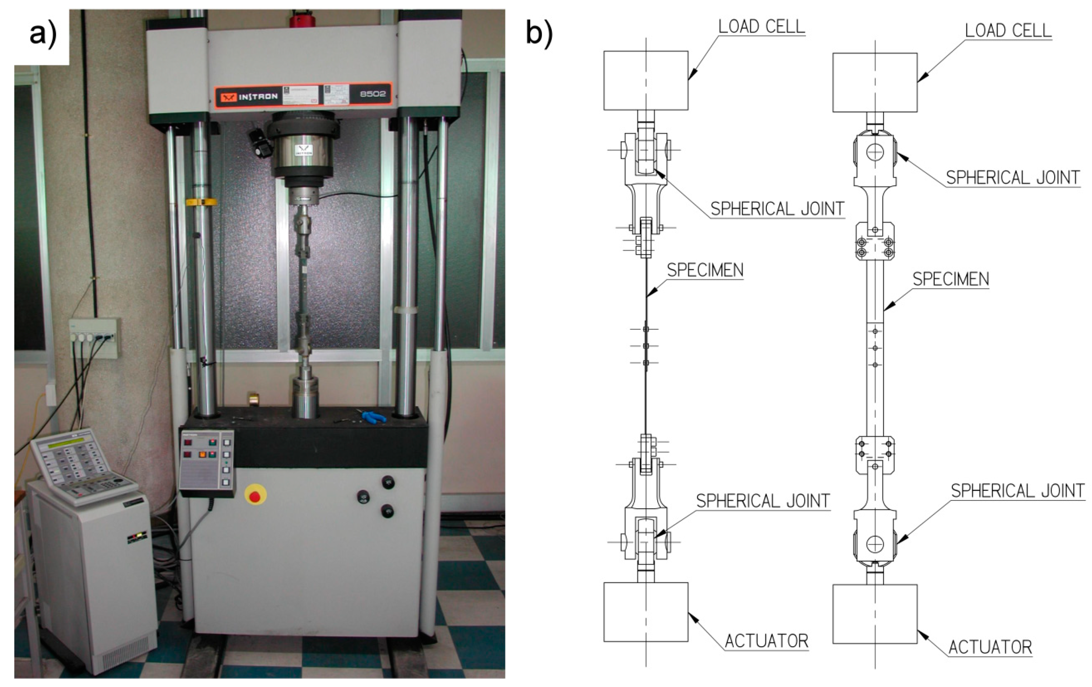
The fatigue tests were carried out at the University of Naples Federico II by using an Instron 8502 servo-hydraulic test machine (Figure 2a). Two hundred specimens were tested under tensile fatigue loads with stress ratio R = 0.05 and a frequency of 10 Hz. The load was applied perpendicularly to the rolling direction of the plate and three different levels of stress were considered for the tests: 90 MPa, 120 MPa and 160 MPa. 100 specimens were tested at a stress level of 90 MPa, while 50 specimens were tested for each of 120 MPa and 160 MPa stress levels. Figure 2b shows the testing machine grip system that ensures the perfect alignment of the specimens in all directions. Since life depends strongly on the riveting force, few preliminary fatigue tests were carried out in order to establish the global position of the S-N curve. Successively, a low intermediate and high stress level was chosen for the tests. Life was defined as the number of cycles leading to the failure, assuming that life consumption by crack growth is short compared to the crack initiation period.
In order to analyze the surface of fracture, some specimens were cut by using a low speed, water-cooled, sectioning machine REMET MT60 and submitted to microscopic analysis. The fracture surfaces were inspected with stereo-microscope LEICA MZ12 with a magnification of 5×.

3. Fatigue Tests Results and Discussion

3.1. Fatigue Life

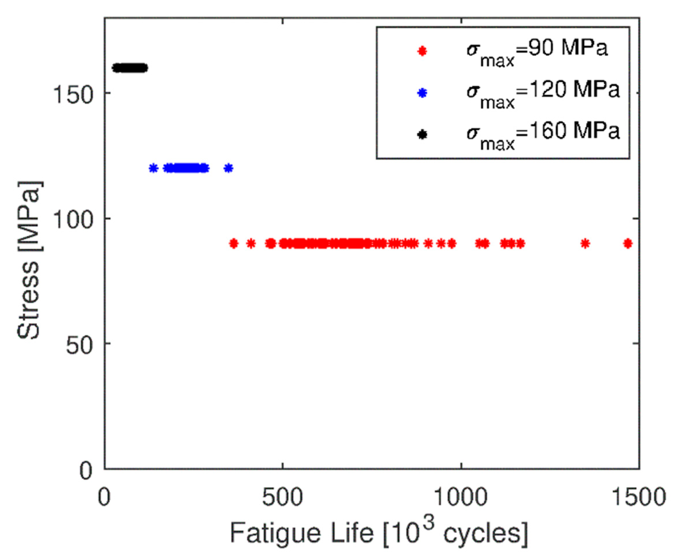
Figure 3 shows the results of fatigue tests in stress (S) vs. the number of cycles (N) for the three different levels of stress, while Table 3 reports the average and the standard deviation values of fatigue life per each stress level. It is possible to observe that the variability of the fatigue life decreases as the level of the fatigue load increases. For the fatigue tests carried out at the lower stress level (90 MPa), the higher variability was found. It depends also on the number of the tested specimens, which is twice the number of the other tests. Such results are coherent with results provided in the literature, as in [12,15,22].

3.2. Critical Crack Size and Location

Specimens were found to fail according to the two main modes: cracks propagating through-hole and in the proximity of the hole, depending on the level of stress. As higher is the level of stress, as higher is the probability of through-hole cracks.
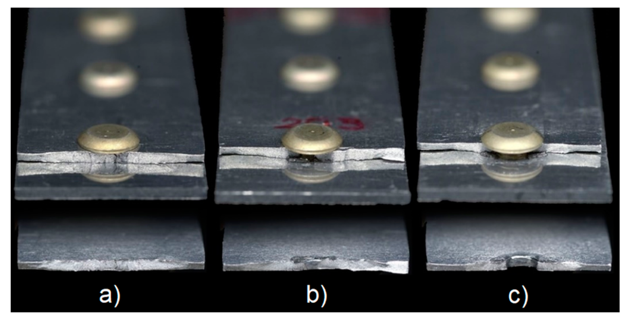
More in detail, for the level of stress of 160 MPa, the cracks propagate predominantly through the hole, for the levels of stress of 90 MPa and 120 MPa, cracks were found to propagate mainly closer, but not through, the hole. Figure 4 shows the different fracture types.
The crack location can be attributed to the clamping pressure, which forces the crack to initiate outside the hole. By increasing the fatigue stress, this clamping pressure is increasingly overruled, and failure is due to the effects of the bearing pressure at the rivet–hole interface. As the bearing pressure increases with the stress level, as more significant is the role played by the notch, because of the complex stress field in this zone. For a lower stress level, at 90 MPa, it can be observed that only 27.2% of the tested specimens showed through-hole cracks, while the remaining 72.8% showed cracks in the proximity of the hole. At 120 MPa, the total of specimens failed at the hole’s cross-section increased and reached 36.3% of specimens. At 160 MPa, as anticipated, the 100% of the specimens failed in correspondence of the hole’s cross-section.
Figure 5 shows the morphology for both failure types.
As can be seen from Figure 5, the crack starts on the faying surface and in general on several macro zones. The macro zones close to the rivet hole (Figure 5a) or in the middle of the specimen cracked in proximity of the hole (Figure 5b) are initiation areas rather than initiation sites. For the through-hole cracked specimens, the cracks did not initiate as corner cracks. This initiation behavior agrees with that described in Wanhill et al. [23].
Another discrimination can be done by considering the crack location on the joint, as shown in Figure 6.
For the levels stress of 90 MPa and 120 MPa, it was observed that 93.7% and 96% of specimens, respectively, failed in correspondence of the zone, indicated in Figure 6a. Percentage changes for the level stress of 160 MPa, where a smaller percentage of specimens, 61.2%, failed in correspondence of such zone, while the remaining part, 38.8%, was closer to the zone shown in Figure 6b.
This difference can be attributed to the clamping pressure, which forces the crack to initiate outside the hole. Such clamping pressure can be different at the location shown in Figure 6a, under the rivet head, and at the location shown in Figure 6b, under the squeezer head. Such an aspect can be addressed also to a not uniform rivet expansion along the hole. By increasing the fatigue stress, this clamping pressure is increasingly overruled, and the failure is induced by the bearing pressure at the rivet–hole, leading the specimens to fail in correspondence of the hole’s cross-section.
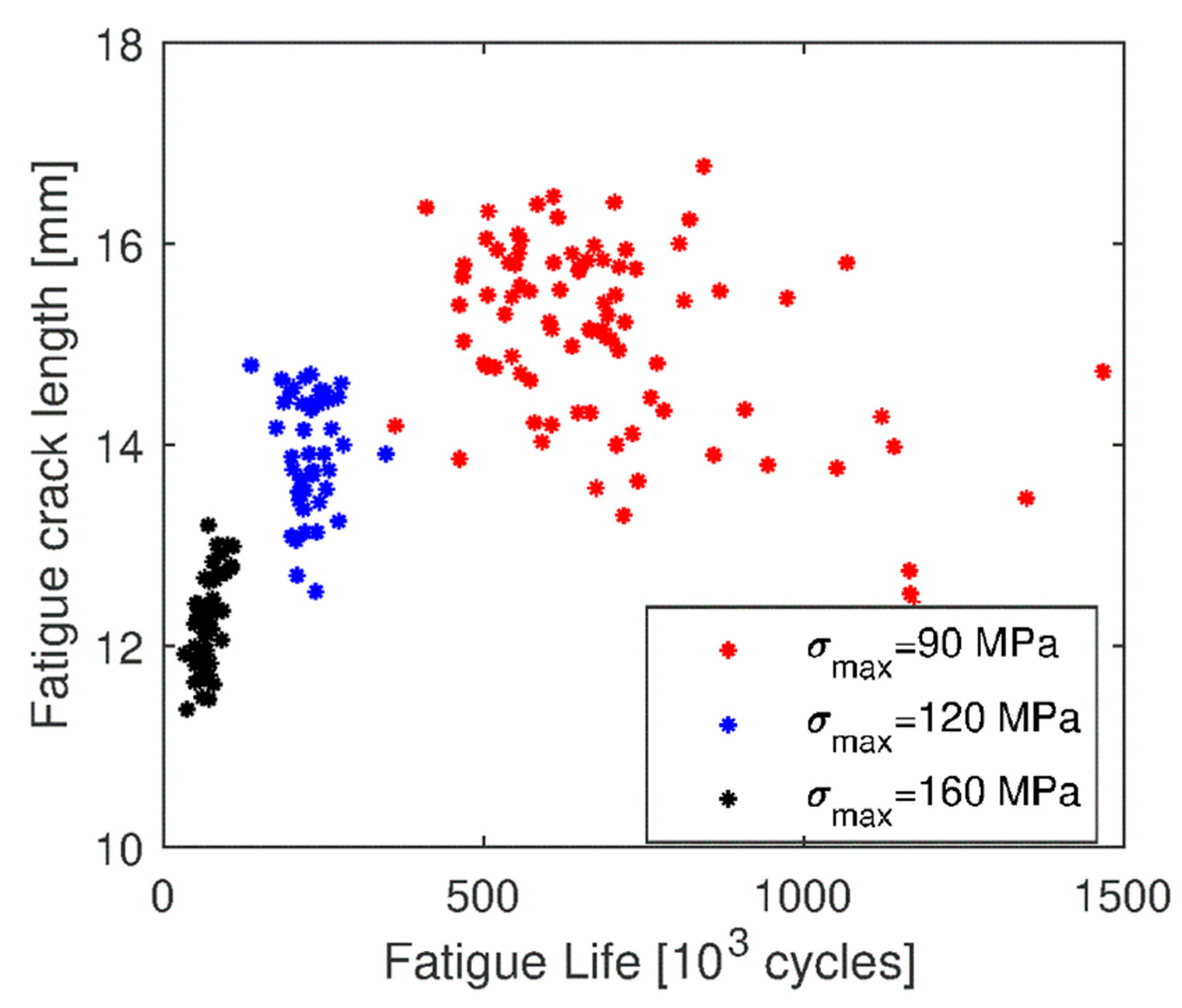
Figure 7 shows the critical fatigue crack length values at the three different levels of stress. The critical crack size decreases as the level of stress increases. Additionally, the average and the standard deviation values of critical crack sizes per each stress level are reported in Table 4. It is worth to note that the variability decreases as the level of stress increases. These results, in general, are coherent with those provided by literature [15,22].

4. Statistical Analysis: Anderson–Darling Test

In order to use the test data for setting up probabilistic methods, the experimental results should be fitted by a distribution function. Many distribution types, such as normal, log-normal, Weibull, Extreme Value, Exponential, etc., are available in statistics and it is very important to determine the distribution that better fits the test data.
The Anderson–Darling test is very suitable [24] and used for application types herein presented [25,26,27]. It allows understanding if there are probabilities that a certain distribution could represent the analyzed data set.
For datasets related to fatigue life and critical crack size, the following distribution types were tested: normal, log-normal, extreme value type and Weibull. The statistical test was performed by means of MATLAB® R2019a code.
Anderson–Darling test [28] is characterized by the statistic value A2, also called goodness of fit statistic, evaluated by Equation (1):
A n 2 = n + { F n ( x ) F 0 ( x ) } 2 F 0 ( x ) { 1 F 0 ( x ) } d F 0
A2 is used to test the hypothesis that a random sample X1, …, Xn, with empirical distribution Fn(x) comes from a continuous population with distribution function F(x), where F(x) = F0(x) for some completely specified distribution function F0(x). Fn(x) is defined as the proportion of the sample X1, …, Xn which is not greater than x.
The value A2 must be compared to its critical value A2crit, which depends on the significance level (α) and on the type of distribution. When the A2 value is lower than A2crit, the supposed distribution type describes adequately the dataset. Vice versa, the hypothesis is rejected.
Table 5 reports the values A2 related to fatigue life and critical crack size datasets. The table also reports the values A2crit at the significance level of 5% (α = 0.05) for each type of distribution [29]. Immediately, it is possible to observe that for the fatigue life dataset at σmax = 90 MPa there are no A2 values lower than A2crit, so the test rejects the supposed distribution types. For crack length at 90 MPa, there is one value of A2 that satisfies the Anderson–Darling requirements. For the other datasets, at σmax = 120 MPa and σmax = 160 MPa, and for both fatigue life and crack size, there are at least two conditions that satisfy the hypothesis of the Anderson–Darling test, highlighted in red in Table 5.
Usually, the test uses probability plots, in which ordered observations are plotted against their observed cumulative frequency, to further verify the best fit. The scale of the cumulative frequency was arranged so that a good fit (low values of A2) results in a straight line and a bad fit (high values of A2) in a significant deviation of the plotted points from a straight line.
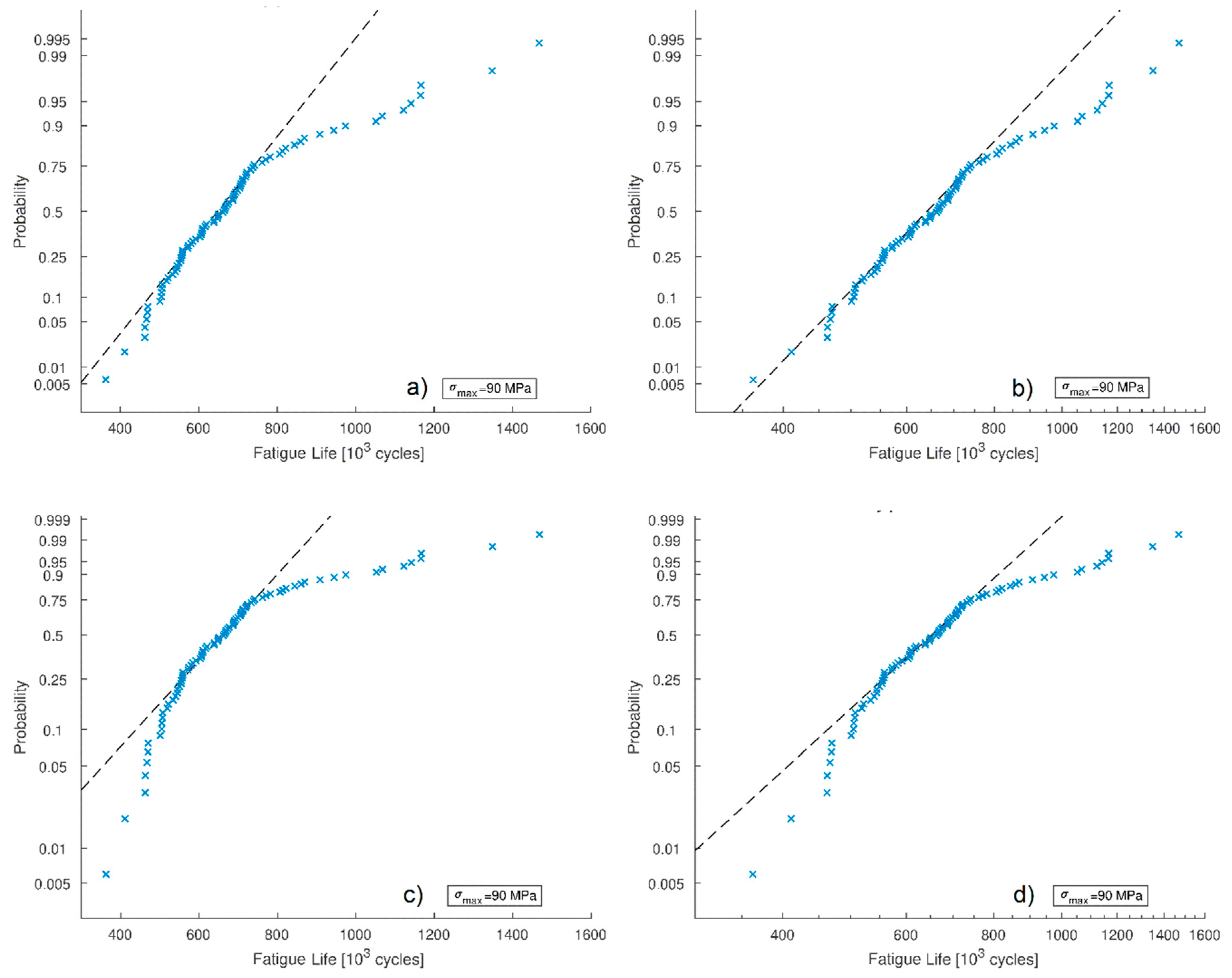
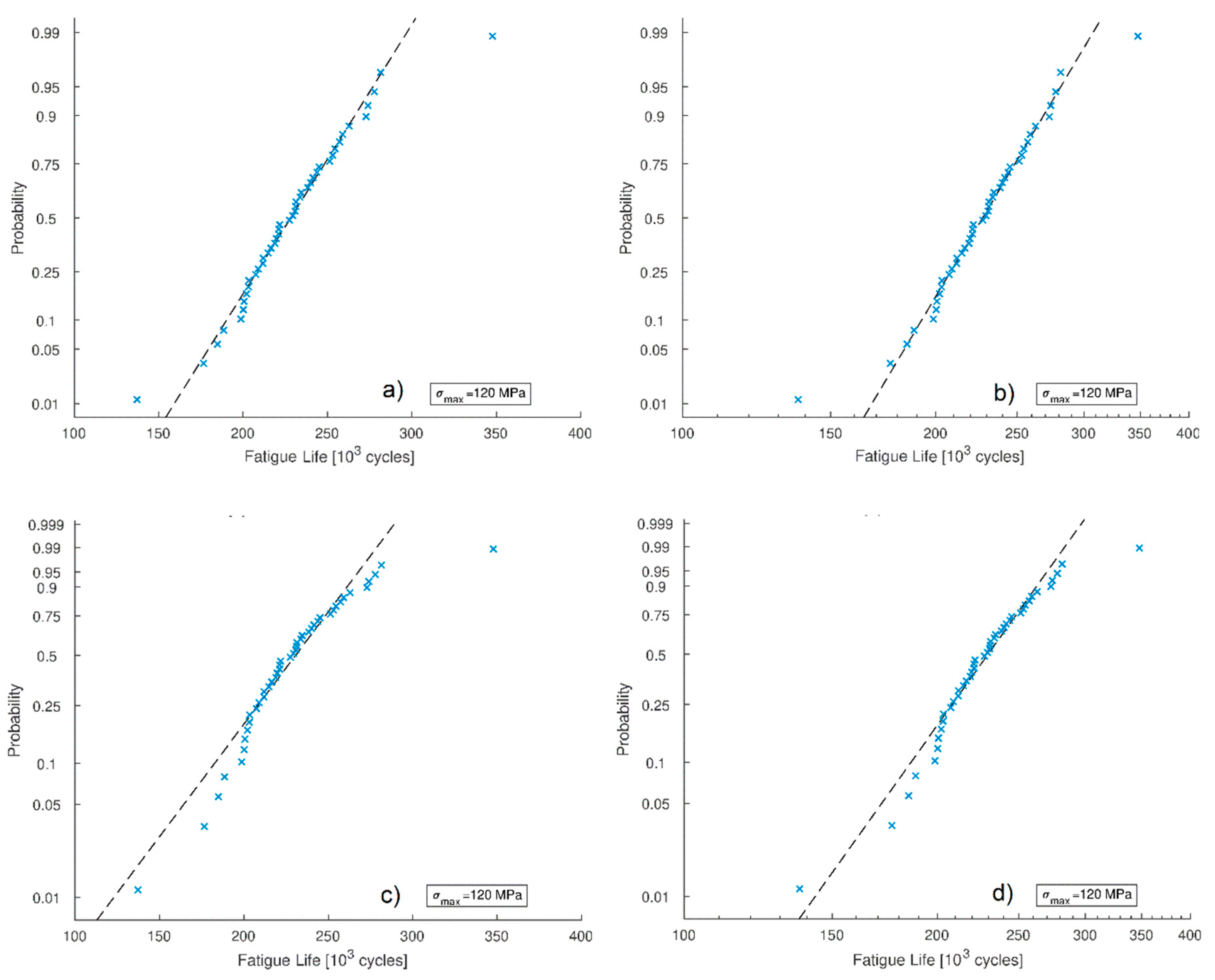
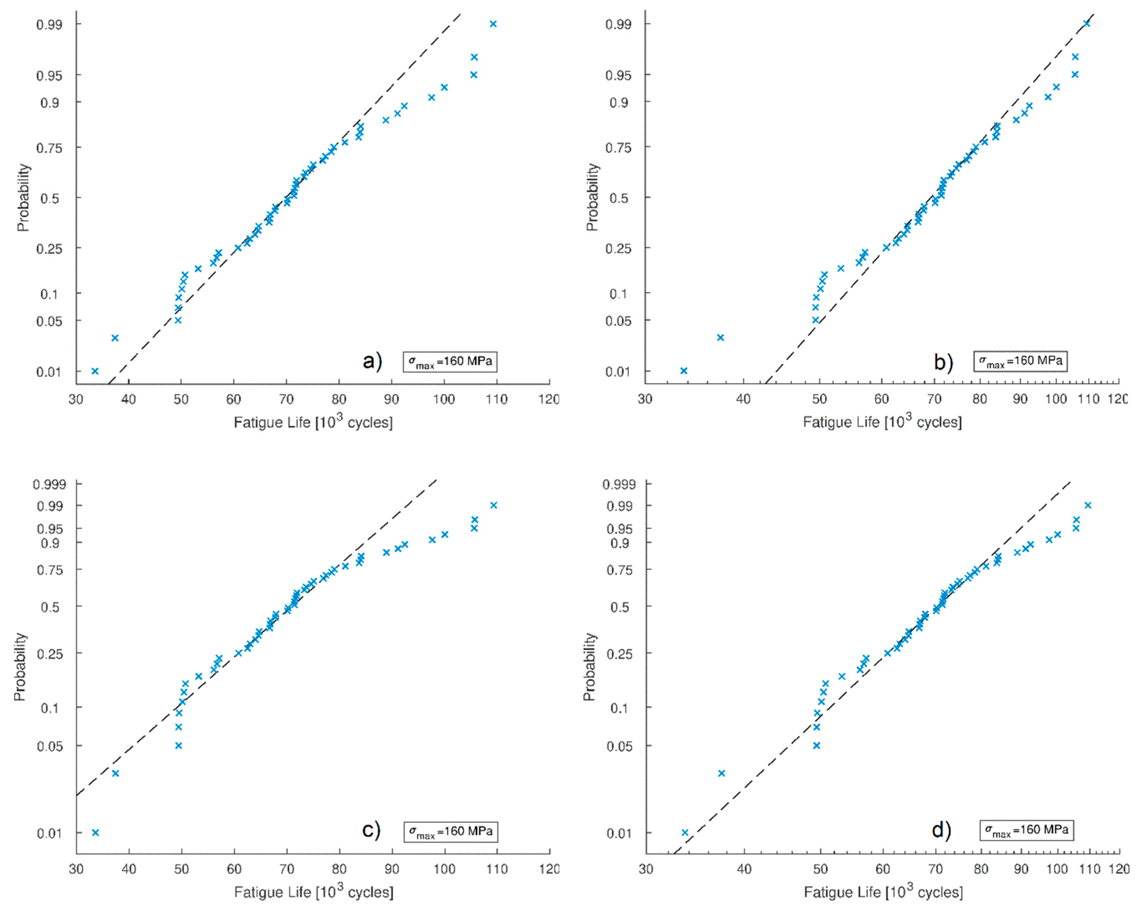
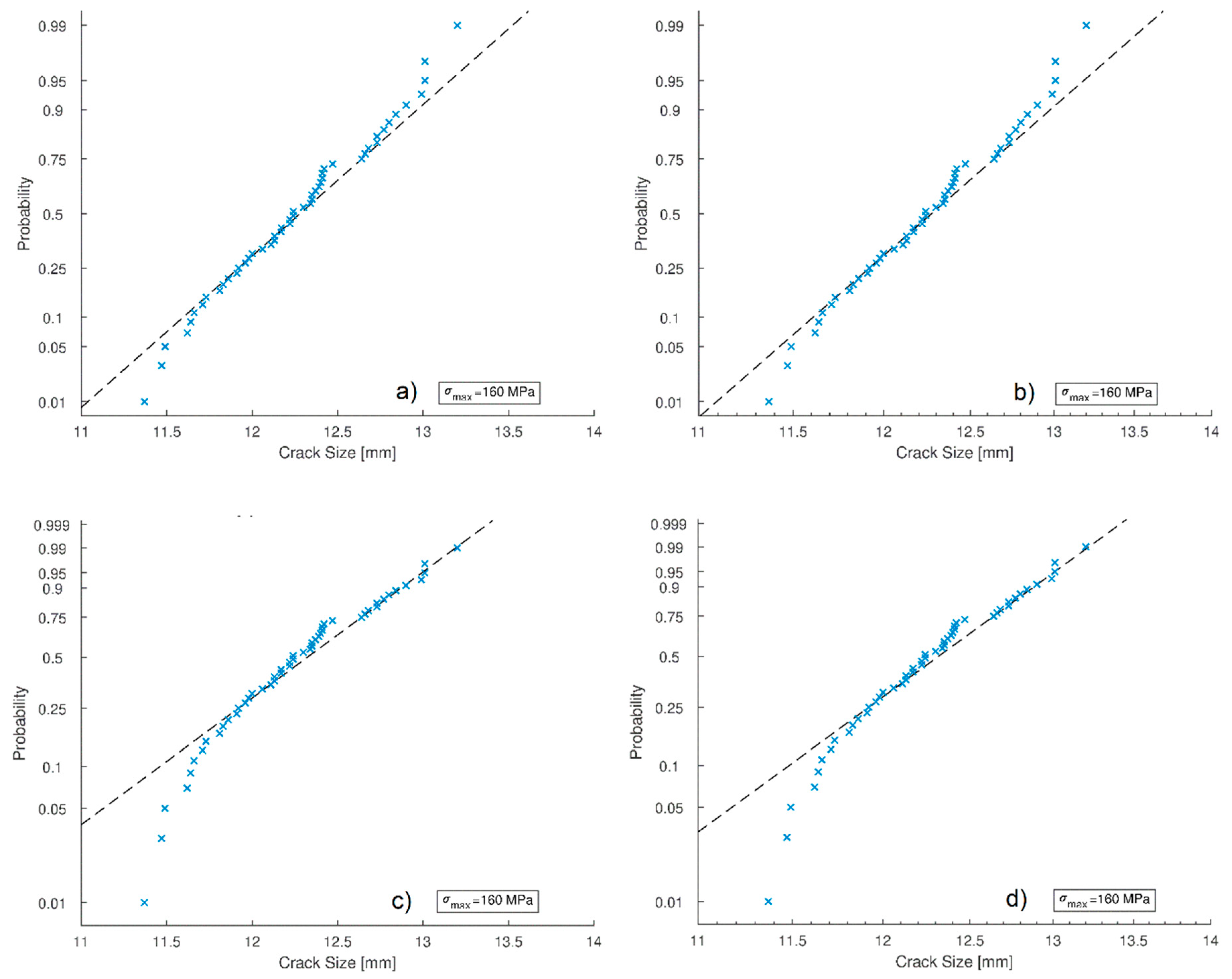
Probability plots of datasets are shown in the following figures: Figure 8, Figure 9 and Figure 10 show the probability plots for fatigue life under the fatigue loads with a stress level of 90 MPa, 120 MPa and 160 MPa, respectively, considering normal, log-normal, extreme value and Weibull distributions. Similarly, Figure 11, Figure 12 and Figure 13 show the probability plot for the critical crack size. It is possible to point out that the fatigue life dataset at a stress level of 90 MPa, as already mentioned, does not fit any supposed distribution (Figure 8). Anyway, splitting the data set into two sub-datasets, with separation at 781,700 cycles due to higher dispersion of subsequent data (Figure 3), which represents the 20% of the whole dataset, both fit normal distribution with A2 equals to 0.5789 and 0.5256 respectively.
The fatigue life dataset at 120 MPa fits both normal and log-normal distributions, as observable by probability plots in Figure 9.
At 160 MPa, the fatigue life dataset (Figure 10) fits three supposed distributions: normal, log-normal and Weibull.
About crack size datasets, all of them seem to better fit a distribution. Dataset at 90 MPa fatigue load (Figure 11) fits Weibull distribution, as verified by the Anderson–Darling test. Similar to the fatigue life dataset at 90 MPa, splitting the crack size data set into two sub-datasets, with separation at 14 mm due to higher dispersion (Figure 7) of previous data (the 14% of the whole dataset), both fit a normal distribution with A2 equal to 0.6714 and 0.7069, respectively.
Both crack size datasets at 120 MPa (Figure 12) and 160 MPa (Figure 13) fatigue loads fit normal, log-normal and Weibull distributions.
Therefore, it can be concluded that fatigue life datasets at 120 MPa and 160 MPa stress levels can fit a normal distribution, while fatigue life dataset at 90 MPa cannot be fitted to any distribution, unless the dataset is split into two sub-datasets, both fitting normal distributions.
For critical crack size, dataset at 90 MPa fits a Weibull distribution, while datasets at 120 MPa and 160 MPa both can fit a normal distribution.

5. Conclusions

A high number of fatigue tests have performed on single riveted lap joint specimens by considering three different levels of stress with stress ratio R = 0.05. Herein, results about fatigue life and critical crack length were shown. As expected, both fatigue life and critical crack size decrease as the level of stress increases.
Moreover, it was interesting to observe that two modes of cracks occurred: through the hole and in proximity of the hole. Bearing pressure at the rivet–hole interface forces the crack to propagate through the hole. As the fatigue stress increases, the bearing pressure increases and the crack tends to propagate through the hole. Indeed, under the fatigue load with a stress level of 90 MPa, less than 30% of specimens showed cracks propagating through the hole. At the stress level of 120 MPa, the percentage increases until reaching 36.3%, while at the stress level of 160 MPa all the specimens failed across the hole.
Finally, aimed to use experimental data for probabilistic methods, a statistical analysis was performed by using the Anderson–Darling test in order to investigate if datasets fit a distribution function.
About fatigue life, it was observed that even if the dataset achieved for the tests at the level stress of 90 MPa does not fit any distribution, both datasets at 120 MPa and 160 MPa level fit normal distributions.
About critical crack size, the test demonstrated that dataset at 90 MPa fits a Weibull distribution while it is possible to affirm that both the datasets at 120 MPa and 160 MPa fit normal distributions.

Author Contributions

E.A.: investigation, methodology; A.G.: writing—original draft, data curation; A.D.L.: resources, writing—review and editing; R.S.: supervision. All authors have read and agreed to the published version of the manuscript.

Funding

This research received no external funding.

Conflicts of Interest

The authors declare no conflicts of interest.

References

  1. Blake, A. Design of Mechanical Joints; Marcel Dekker Inc: New York, NY, USA, 1985. [Google Scholar]
  2. Chen, Y.; Yang, X.; Li, M.; Wei, K.; Li, S. Mechanical behavior and progressive failure analysis of riveted, bonded and hybrid joints with CFRP-aluminum dissimilar materials. Thin. Walled. Struct. 2019, 139, 271–280. [Google Scholar] [CrossRef]
  3. Hossein Cheraghi, S. Effects of variation in the riveting process on the quality of riveted joints. Int. J. Adv. Manuf. Tech. 2008, 39, 1144–1155. [Google Scholar] [CrossRef]
  4. Chowdhyry, N.; Chiu, W.K.; Wang, J.; Chang, P. Static and fatigue testing thin riveted, boned and hybrid carbon fiber double lap joints used in aircraft structures. Compos. Struct. 2015, 121, 315–323. [Google Scholar] [CrossRef]
  5. Henssen, A.; Olovsoon, L.; Porcaro, R.; Langseth, M. A large-scale finite element point-connector model for self-piercing rivet connections. Eur. J. Mech. Solids. 2010, 29, 484–495. [Google Scholar] [CrossRef]
  6. Vivio, F. A new theoretical approach for structural modelling of riveted and spot welded multi-spot structures. Int. J. Solid. Struct. 2009, 46, 4006–4024. [Google Scholar] [CrossRef]
  7. Hassanifard, S.; Adibeig, M.R.; Mohammadpour, M.; Varvani-Farahani, A. Fatigue life of axially loaded clamped rivet-nut joints: experiments and analyses. Int. J. Fatigue 2019, 129, 105254. [Google Scholar] [CrossRef]
  8. Di Cicco, F.; Fanelli, P.; Vivio, F. Fatigue reliability evaluation of riveted lap joint using a new rivet element and DFR. Int. J. Fatigue 2017, 101, 430–438. [Google Scholar] [CrossRef]
  9. Mohammadpour, M.; Kalajahi, M.H.; Oskouei, R.H.; Shakouri, M. Fatigue life estimation of coach peel riveted joints using multi-axial fatigue criteria. Mater. Des. 2014, 62, 327–333. [Google Scholar] [CrossRef]
  10. Da Silva, L.F.M.; Carbas, R.J.C.; Critchlow, G.W.; Figureido, M.A.V.; Brown, K. Effect of material, geometry, surface treatment and environment on the shear strength of single lap joints. Int. J. Adhes. Adhes. 2009, 29, 621–632. [Google Scholar] [CrossRef] [Green Version]
  11. Skorupa, A.; Skorupa, M. Riveted Lap Joints in Aircraft Fuselage. Design, Analysis and Properties; Springer: New York, NY, USA, 2012. [Google Scholar]
  12. Skorupa, M.; Machniewicz, T.; Skorupa, A.; Korbel, A. Fatigue strength reduction factors at rivet holes for aircraft fuselage lap joints. Int. J. Fatigue 2015, 80, 417–425. [Google Scholar] [CrossRef]
  13. Liao, M.; Shi, G.; Xiong, Y. Analytical methodology for predicting fatigue life distribution of fuselage splices. Int. J. Fatigue 2001, 23, 177–185. [Google Scholar] [CrossRef]
  14. Li, G.; Shi, G.; Bellinger, N.C. Stress in triple-row riveted lap joints under the influence of specific factors. J. Aircraft. 2011, 48, 527–539. [Google Scholar] [CrossRef]
  15. Newmann, J.C.; Ramakrishan, R. Fatigue crack-growth analyses of riveted lap-joints in a retired aircraft. Int. J. Fatigue 2016, 82, 342–349. [Google Scholar] [CrossRef]
  16. Yeter, E. Thermal fatigue analyses of riveted structures. Mechanics 2018, 24. [Google Scholar] [CrossRef]
  17. De Jesus, A.M.; Pinto, H.; Fernàndez-Canteli, A.; Castillo, E.; Correia, J.A. Fatigue assessment of a riveted shear splice based on a probabilistic model. Int. J. Fatigue 2009, 32, 453–462. [Google Scholar] [CrossRef]
  18. Pilkey, W.D.; Pilkey, D.F. Peterson’s Stress Concentration Factors, 3rd ed.; John Wiley & Sons: Hobeken, NJ, USA, 2008. [Google Scholar]
  19. Huang, W.; Wang, T.J.; Garbatov, Y.; Soares, C.G. Fatigue reliability assessment of riveted lap joint of aircraft structures. Int. J. Fatigue 2012, 43, 54–61. [Google Scholar] [CrossRef]
  20. Huang, W.; Wang, T.-J.; Gorbatov, Y.; Soares, C.G. DFR based fatigue reliability assessment of riveted lap joint accounting for correlations. Int. J. Fatigue 2013, 47, 106–114. [Google Scholar] [CrossRef]
  21. EverySpec.com. Available online: http://everyspec.com/MIL-HDBK/MIL-HDBK-0001-0099/MIL-HDBK-5J_NOTICE-2_11340/ (accessed on 10 April 2020).
  22. Conner, Z. Quantitative Investigation of Surface and Subsurface Cracks Near Rivets in Riveted Joints Using Acoustic, Electron and Optical Microscopy. Ph.D. Theses, Northwestern University Center for Nondestructive Evaluation Theses and Dissertations, Chicago, IL, USA, 2000. [Google Scholar]
  23. Wanhill, R.J.H.; Hattenberg, T.; Van der Hoeven, W. A Practical Investigation of Aircraft Pressure Cabin MSD Fatigue and Corrosion, NLR Contract Report CR-2001-256; National Aerospace Laboratory NLR: Amsterdam, The Netherlands, June 2001. [Google Scholar]
  24. Razali, N.M.; Wah, Y.B. Power comparisons of shapiro-wilk, kolmogorov-smirnov, lilliefors and Anderson-darling tests. J. Statistical. Model. Analyt. 2011, 2, 21–33. [Google Scholar]
  25. Kasu, S.R.; Deb, S.; Mitra, N.; Muppireddy, M.; Kusam, S.R. Influencce of aggregate size on flexural fatigue response of concrete. Constr. Build. Mater. 2019, 229, 116–922. [Google Scholar] [CrossRef]
  26. Bag, A.; Delbergue, D.; Bocher, P.; Lévesque, M.; Brochu, M. Statistical analysis of high cycle fatigue life and inclusion size distribution in shoot peened 300M steel. Int. J. Fatigue 2019, 118, 126–138. [Google Scholar] [CrossRef]
  27. Tellom, L.; Castejon, L.; Malon, H.; Valladares, D.; Luque, P.; Mantaras, D.A.; Ranz, D.; Cuartero, J. Development of a fatigue life prediction methodology for welded steel semi-trailer components bassed on a new criterion. Eng. Fail. Anal. 2020, 108, 104268. [Google Scholar] [CrossRef]
  28. Anderson, T.W.; Darling, D.A. A test of goodness of fit. J. Am. Stat. Assoc. 1954, 49, 765–769. [Google Scholar] [CrossRef]
  29. Jäntschi, L.; Bolboacă, S.D. Computation of probability associated with Anderson-Darling statistic. Mathematics 2018, 6, 88. [Google Scholar] [CrossRef] [Green Version]
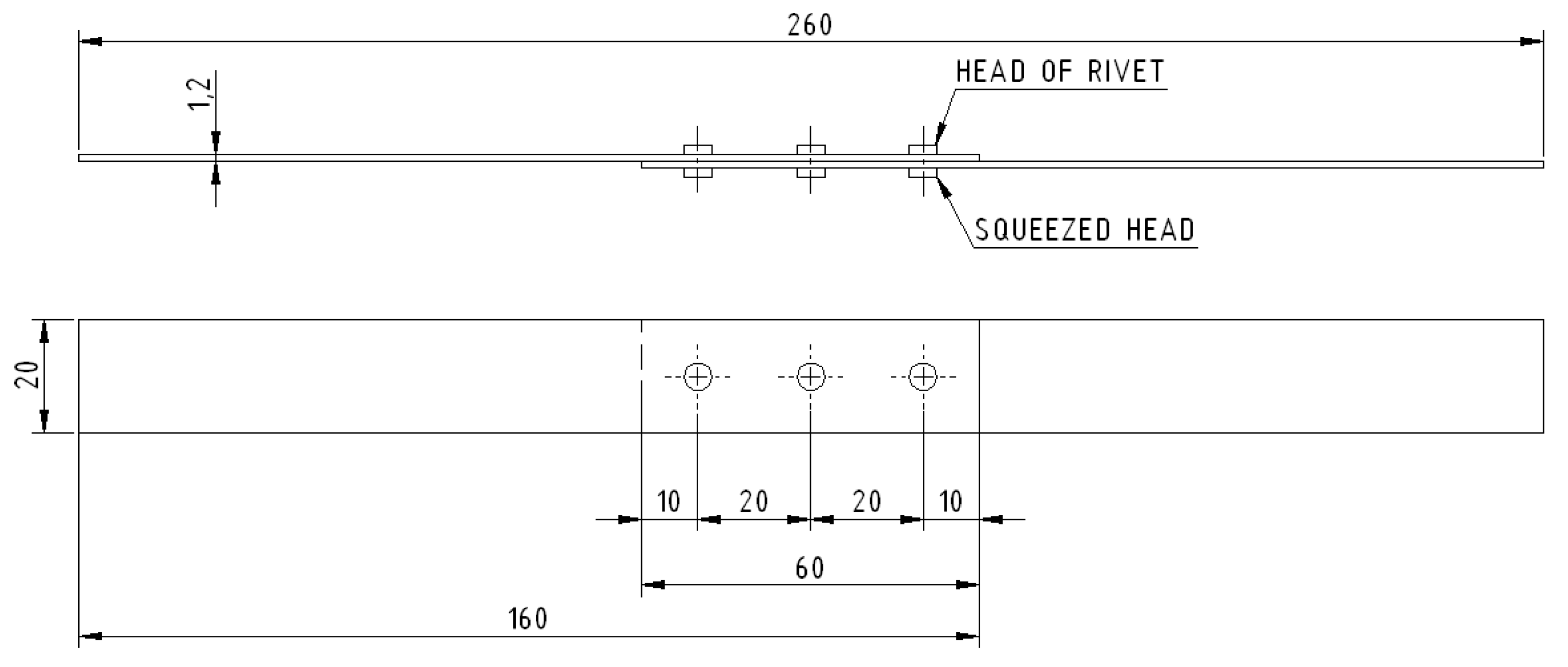
Figure 1. Test article geometry.
Applsci 10 03379 g001
Figure 2. Fatigue test: Instron 8502 fatigue test machine (a); grip system (b).
Applsci 10 03379 g002
Figure 3. S-N graph for fatigue tests at three different levels of stress.
Applsci 10 03379 g003
Figure 4. Crack types: in the proximity of the hole at 90 MPa (a) and at 120 MPa (b); through-hole at 160 MPa (c).
Applsci 10 03379 g004
Figure 5. Examples of crack morphology: through-hole (a) and in proximity of the hole (b).
Applsci 10 03379 g005
Figure 6. Crack locations in the specimen.
Applsci 10 03379 g006
Figure 7. Critical crack size at three different levels of stress.
Applsci 10 03379 g007
Figure 8. Fatigue life at 90 MPa: probability plots for normal (a), log-normal (b), extreme value (c) and Weibull (d) distributions.
Applsci 10 03379 g008
Figure 9. Fatigue life at 120 MPa: probability plots for normal (a), log-normal (b), extreme value (c) and Weibull (d) distributions.
Applsci 10 03379 g009
Figure 10. Fatigue life at 160 MPa: probability plots for normal (a), log-normal (b), extreme value (c) and Weibull (d) distributions.
Applsci 10 03379 g010
Figure 11. Critical crack size at 90 MPa: probability plots for normal (a), log-normal (b), extreme value (c) and Weibull (d) distributions.
Applsci 10 03379 g011
Figure 12. Critical crack size at 120 MPa: probability plots for normal (a), log-normal (b), extreme value (c) and Weibull (d) distributions.
Applsci 10 03379 g012
Figure 13. Critical crack size at 160 MPa: probability plots for normal (a), log-normal (b), extreme value (c) and Weibull (d) distributions.
Applsci 10 03379 g013
Table 1. Chemical composition of Al 2024 T3 (wt%).
MaterialCuMgMnFeCrSiTiZnAl
Al 2024-T33.8–4.91.2–1.80.3–0.9≤0.5≤0.1≤0.5≤0.15≤0.25Balance
Table 2. Mechanical properties of Al 2024 T3.
Materialσs [MPa] (S)σr [MPa] (S)E [MPa] (S)Z [%] (S)
Al 2024-T3296 (5.35)426 (4.42)71000 (2121)13 (1.5)
Table 3. Average and standard deviation values for fatigue life.
Load Level [MPa]Average Value of Fatigue Life [103 cycles]Standard Deviation for Fatigue Life [103 cycles]
90693.2205.1024
12023134.1735
16070.916.9139
Table 4. Average and standard deviation values for crack length.
Load Level [MPa]Average Value of Crack Length [mm]Standard Deviation for Crack Length [mm]
9015.10.9085
12013.9030.5915
16012.25640.448
Table 5. Critical and test Anderson–Darling statistic values, A2crit and A2, for most common distribution types for fatigue life and crack size datasets.
Distribution Types
NormalLog-NormalExtreme ValueWeibull
A2critα = 0.05 *0.7520.752n = 100 *n = 500.757
0.2790.277
A2 Fatigue life datasetσmax [MPa]903.23301.05957.29893.7891
1200.48070.42652.32511.3094
1600.38480.43881.43890.5885
A2 Crack size datasetσmax [MPa]901.04371.28400.34960.3910
1200.69900.72630.75940.7441
1600.22530.21720.72990.6366
A2 < A2crit* α = significance level; n = sample size