Article

Viscoelastic Finite Line Contact of Thin Bonded Layered Solids of Low Elastic Modulus

by
Vasilis Votsios
1,
Patricia Johns-Rahnejat
2,* and
Homer Rahnejat
2
1
Airbus Operations S.L., 28906 Getafe, Spain
2
School of Engineering, University of Central Lancashire, Preston PR1 2XQ, UK
*
Author to whom correspondence should be addressed.
Appl. Sci. 2020, 10(10), 3363; https://doi.org/10.3390/app10103363
Submission received: 8 April 2020 / Revised: 8 May 2020 / Accepted: 8 May 2020 / Published: 13 May 2020
(This article belongs to the Section Mechanical Engineering)

Abstract

:
A new finite element-based contact mechanics analysis of layered viscoelastic solids of low elastic modulus is presented. The methodology is based on the Maxwell viscoelastic element, with stress relaxation taken into account by the Prony series’ representation of the bulk and shear material moduli. Simultaneous solutions for deviatoric and volumetric stresses were obtained under instantaneous elastic and subsequent viscoelastic relaxation, at multiples of the relaxation time of a Highly Filled Carbon Polymer (HFCP) layer. The results of the analysis were validated by a constructed, multi-layered sandwich sensor comprising the HFCP sensing elements covered by a protective silicone rubber surface of very low elastic modulus. The combined numerical-experimental approach, and the validated viscoelastic layered contact mechanics represent the original contribution of this paper, not hitherto reported in literature.

1. Introduction

In recent years, increasing use has been made of load bearing polymeric or elastomeric surfaces as compliant members, for example in journal bearings [1,2] or as lip seals or O-rings [3,4,5]. In these applications, localised deformation of the polymeric soft layer increases the gap between the contacting surfaces, which can enhance the lubricant film separating them, thus reducing friction. In other applications, soft layers are intended to act as protective layers.
Polymeric and elastomeric surfaces act in a viscoelastic manner with stress relaxation [6,7]. In bearings, the compliant members are usually in conforming contacts. In other cases, the viscoelastic layers suffer higher contact pressures when subjected to non-conforming contacts. In these cases, the contact characteristics depend on the layer thickness. In general, the contact mechanics of thin bonded layers deviate from the classical Hertzian contact mechanics, which admits only small strain localised deformation for assumed semi-infinite solids [8]. For viscoelastic semi-infinite solids of polymeric and elastomeric surfaces, where the contact footprint dimensions are far smaller than the layer thickness, Johnson [6] provided an analytical solution for an assumed infinite line contact, based on the Maxwell model. Naghieh et al. [7,9] provided solutions for non-conforming point contacts of thin bonded viscoelastic solids, showing deviation from semi-infinite solutions. They showed that Hertzian theory underestimates the generated contact pressures for thin compliant layers whose contact dimensions exceed the layer thickness by a ratio greater than two. In many cases an analytical solution cannot be assumed and a numerical analysis technique, such as finite difference or finite element, must be developed. This is the main motivation of this paper. Furthermore, Naghieh et al. [7,9] solutions for point contact and those of Johnson [6] for infinite line contact do not apply to the finite line contact geometry of many non-conforming contacts, for example in rolling element bearings with raceways [10,11] or cam contact with a flat tappet [12]. These contacts with finite line footprint geometry have edge stress concentrations at the contact extremities, inducing pressure spikes [10,11,12,13,14]. Therefore, another motivation of the current work is the development of a generic numerical analysis technique able to predict the edge stress discontinuities, such as pressure spikes, which often determine the limit of structural integrity of contacting solids. The same is true when a flat indenter contacts a thin polymeric viscoelastic layer, as in the case studied here. Therefore, such an experiment is used to validate finite element analysis of the finite line contact of the indenter against the viscoelastic layer of low elastic modulus represented by the Highly Filled Carbon Polymer (HFCP). This approach enables the development of elements with the correct choice of constitutive (stress–strain) relationship. The current highlighted predictive finite element-based viscoelastic layered contact mechanics approach is original, not hitherto reported in literature.
As noted above, the results of the predictive analysis are compared with experimental contact mechanics using a pressure sensitive sandwich sensor made of small pieces of a Highly Filled Carbon Polymer (HFCP), bonded to a thin, flexible printed circuit board tape. Such skin sensors have been developed for biomedical applications and for tactile devices, mostly for robotics, some with contact imaging, based on finite element analysis techniques [15,16,17,18,19,20]. HFCP layers contain a certain high percentage of carbon whose conductance alters fairly linearly with applied pressure [16]. However, the polymer layer is usually quite thin and susceptible to tear with repetitive use. Thus, a sandwich layered structure is preferred. Such a layered solid can emulate the histological structure of the human skin, at least in parts [18]. The sandwich structure can also stretch like human skin, providing the necessary suppleness that ensures connectivity. However, with most polymeric sensors there exists a small degree of non-linearity in measurements with applied pressure, hysteresis and drift in conductivity, particularly after repeated use.

2. The Layered Bonded Sensor Structure

The in-house manufactured layered sandwich sensor shown schematically in Figure 1a, comprising a top protective layer of silicone rubber with a thickness of 1–1.5 mm. The 5 MPa modulus of elasticity of this layer is quite low. Thus, the stresses generated in it are readily passed on to the lower layers of the sandwich sensor, as is the case for all substrate materials protected by soft overlays [6,21,22].
Figure 1 shows the sensor structure comprising a cell in the centre and four others at each corner of an area of 4 × 4 mm2. There are four such structures making the overall layered solid sandwich sensor. With this arrangement there are a sufficient number of cells to provide measurement sensitivity for a class of contacts, such as planar or line contacts along the indicated axes in the figure. Beneath the silicone rubber protective top layer, small pieces of HFCP (1 mm2 in area with a thickness of 100 µm) are bonded onto a network of electrical circuits that are etched upon a flexible PCB tape. The tape has a thickness of 50 µm, rendering it suitable for wrapping around objects such as fingertips, for example for anthropomorphic prosthetic hands [23]. The circuit’s copper tracks have an infinitesimal thickness of 17.5 µm. The electrical signals generated due to changes in HFCP variable conductance are transmitted through the fabricated copper track to the Microlink data acquisition system (Microlink Co., Manchester, UK), which converts the analogue voltage data to a digital signal. This is carried out at the rate of 25,000 samples/second. This sampling rate is more than sufficient for the required monitoring changes at multiples of relaxation time, τ , of the HFCP. The modulus of elasticity of HFCP is 1 GPa with a Poisson’s ratio of 0.4. This renders the sensor a viscoelastic compressible device in contact mechanics parlance.
The HFCP-based sensing elements adapt slowly to applied pressure with a relaxation time of approximately 0.9 s. The results, described later, indicate an adaptation time in the range 0.9–4.5 s. The spacing between the sensing sites is kept between 1–2 mm, depending on the design of the sandwich sensor. The area density of the sensing is usually 1.25 sensors/mm2, which is sufficient for the purpose of contact mechanics analysis when indenting the layered structure with a flat rigid indenter. A combination of four sensor structures (Figure 1a) are used in the configuration matrix shown in Figure 1b. Therefore, there are 10 sensing sites positioned radially over half of the contact area of the flat circular punch used in the current study. For a perfectly flat indenter, as well as a perfectly flat and frictionless silicone rubber surface under purely direct normal load, the pressure distribution is nominally symmetrical about both axes of the contact footprint area shown in Figure 1b.

3. Experimental Procedure

Figure 2 shows the simple experimental set up comprising a flat rigid platen, upon which the layered sandwich sensor is mounted, and an indentation rig consisting of a pin of flat circular cross-section mounted on a horizontal lever. The pin surface is initially positioned tangential to the sensor surface. The lever is then articulated about its hinge position through a very small angle (less than 0.1°) when various masses are placed in the weight hanger. The small angle of articulation ensures a nominally aligned normal contact between the pin and the sensor surfaces. There is a lever mechanical advantage of 2:1, so the applied contact load is twice the placed weights.
When a contact load is applied to the layered solid, the silicone rubber (having a low elastic modulus) deforms, conforming to the shape of the indenter, and transmits the effect of pressure onto the HFCP pieces (sensing sites). The conductance of the HFCP pieces alters with the application of pressure and the signal outputs from all the sensing sites are transmitted via the electrical network circuit fabricated upon the PCB tape to a multi-channel data acquisition system. The data acquisition rate is set at 0.5 samples/second. This is approximately half the relaxation time of the HFCP, thus reducing the chance of aliasing. Simultaneous acquisition for all the 10 sensing sites is carried out. The indentation tests for each load, and for various durations as multiples of the HFCP relaxation time, are performed 16 times in each case and an average is taken. This action eliminates all potential sources of error.
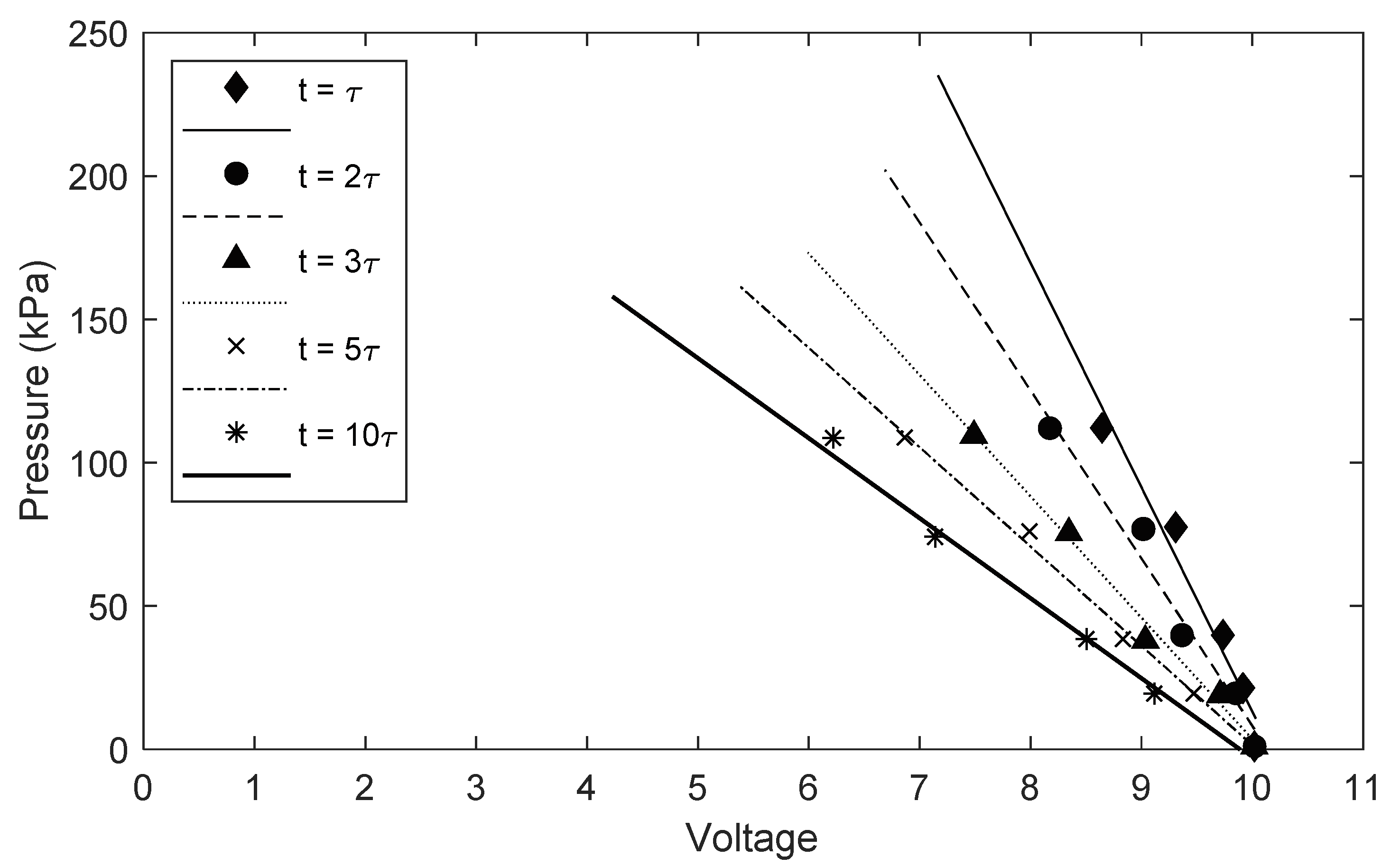
Elemental sensing site output voltage decreases with an increasing pressure, and with increasing relaxation time. Each sensing site is calibrated individually as there are small piece-to-piece deviations in HFCP conductance. These calibration curves are for the various sensing locations. It is assumed that there is little variation between the sensing elements’ characteristic outputs under the same applied load and relaxation time. Figure 3 shows the calibration curves for the sensor configuration in Figure 1b. The maximum voltage output from a sensing site is 10 V with no applied load. Calibration curves are obtained for different applied loads and multiples of relaxation time of the HFCP (Figure 3).
The prehensile human finger contact force is usually in the range 1–8 N. Therefore, the indentation tests are carried out under a normal load within this range. The contact dimensions depend on the applied load and grow with relaxation because of the sensor’s viscoelastic behaviour. The highest pressures occur instantaneously (i.e., at the instance the load is applied). This corresponds to the initial elastic response of the layered solid. Subsequently, the contact pressures reduce as the contact area grows with relaxation. Capturing the instantaneous elastic response is hard to acquire, particularly for layered solids with short relaxation times such as HFCP. Therefore, the results are recorded for multiples of relaxation time up to a point where insignificant changes in contact pressures are observed. Ideally, the contact footprint area can be measured by optical interferometry [24]. However, with such a flat indenter, the contact area is large, precluding the need for such an accurate measuring technique. A uniform covering of “engineering blue” paste is used to leave a footprint mark upon the white surface of the silicone rubber. The contact radius can then be measured from this impression using an accurate micrometer scale to adequately determine the growth of the contact area with viscoelastic relaxation.

4. Experimental Results

Table 1 lists the averaged sensor output voltage for the various sensors under the applied indentation load of 3.9 N. Note that the various values in each column show the relaxed value of the output voltage with time (as whole multiples of the HFCP relaxation time, τ = 0.9 s). These values are converted to equivalent contact pressures, using the appropriate calibration lines in Figure 3, and plotted along the appropriate axes shown in Figure 1b.
The footprint area is slightly larger than the cross-sectional area of the flat indenter. This is because under the indentation load, the material of the soft protective silicone rubber layers is pulled into the contact area. The contact area also gradually increases in dimensions with relaxation. The footprint area is obtained from the impression made by the “engineering blue” gel on the epithelial layer of the silicone rubber under all the indentation loads and at different multiples of the relaxation time of HFCP. Table 2 lists the contact area for various values of load and at different relaxation time multiples.
The voltage output per sensing site has a maximum of 10 volts, corresponding to no contact condition. When a sensing site is directly contacted, the change in the conductance of HFCP results in a corresponding drop in the voltage output. There is a linear relationship between pressure and voltage output. This depends upon the relaxation time of HFCP as can be observed in Figure 3.
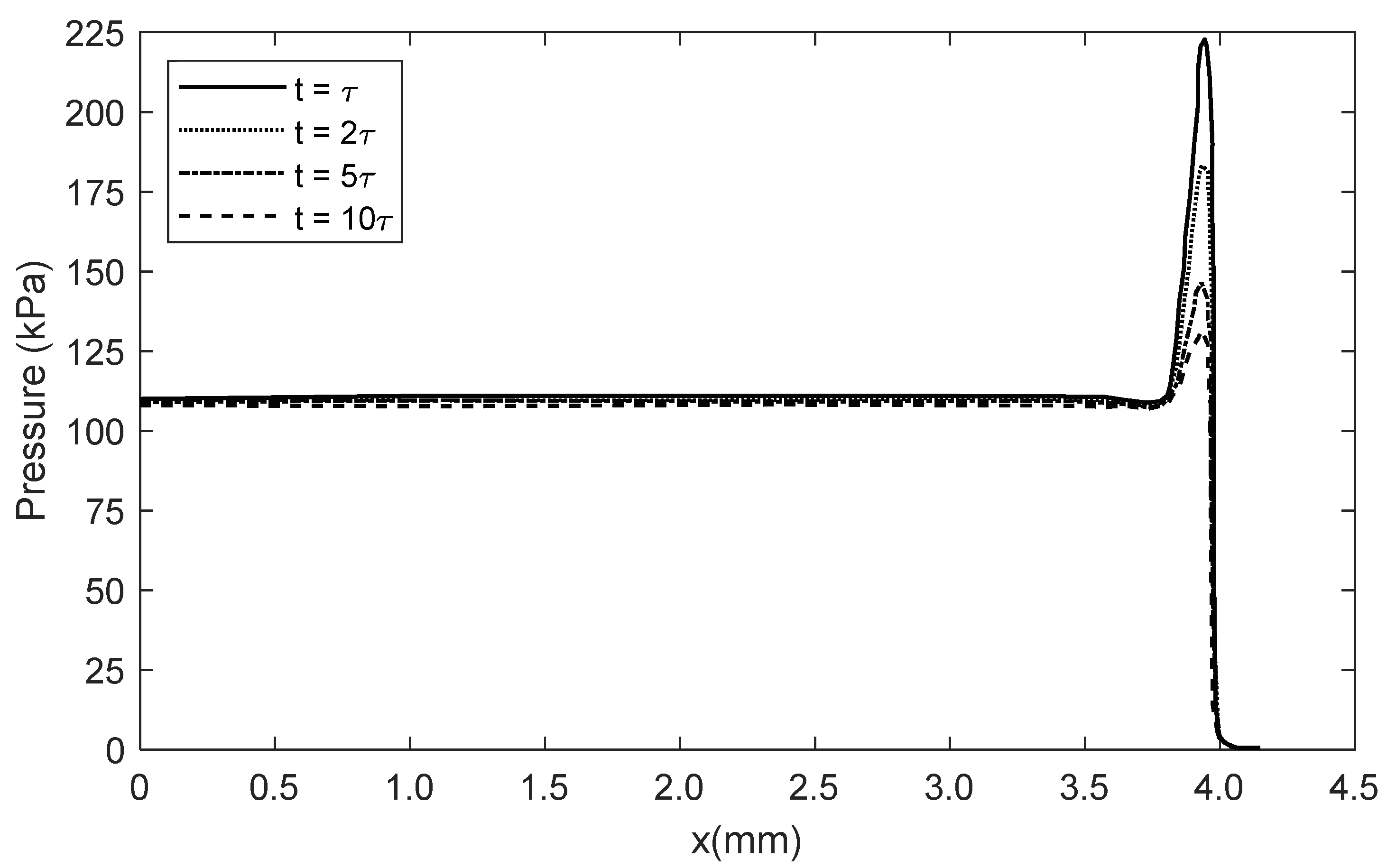
Figure 4 shows the pressure distribution along the x-axis (shown in Figure 1b) for an applied contact load of 3.9 N. The pressure profiles in the figure are axisymmetric about the vertical pressure axis (i.e., half the distribution is shown in the figure). The pressure spike at the edge of the contact is caused by the stress concentration there. This is because of a sharp change in the axial profile of the indenter. This effect is observed in finite line contacts, for example in the contact of unblended rollers against a semi-infinite elastic solid [6,10,11]. The same is true for the contact of a flat indenter (punch) against an elastic half-space [6]. Finite difference or finite element solutions show a finite pressure in the vicinity of the edge of the contact, which can be as much as several times the central region of the pressure distribution.
The magnitude of the pressure spike is largest under the instantaneous application of a load, corresponding to the initial instantaneous elastic response of the layer. This instantaneous pressure distribution is difficult to record experimentally for materials with low relaxation times, such as the HFCP polymer. Therefore, the results are presented at t = τ and its higher multiples. Relaxation characteristics of the polymer result in a drop in the magnitude of pressure spike with time. This is clearly observed in Figure 4. The central portion of the pressure distribution is approximately equal to the average (i.e., Pascal) pressure of P = W A . This indicates that for a contact of assumed infinite dimensions, the pressure would remain constant throughout the contact. However, for a finite planar contact, a pressure spike is formed at the edge of the contact. The average central pressure is almost unaffected by relaxation, but the magnitude of the pressure spike is reduced with relaxation, as would be expected. The rate of reduction decays with increasing relaxation time. The rate of decay is accelerated with higher contact loads as can be observed by comparing the results in Figure 4 with those in Figure 5 for an increased contact load.
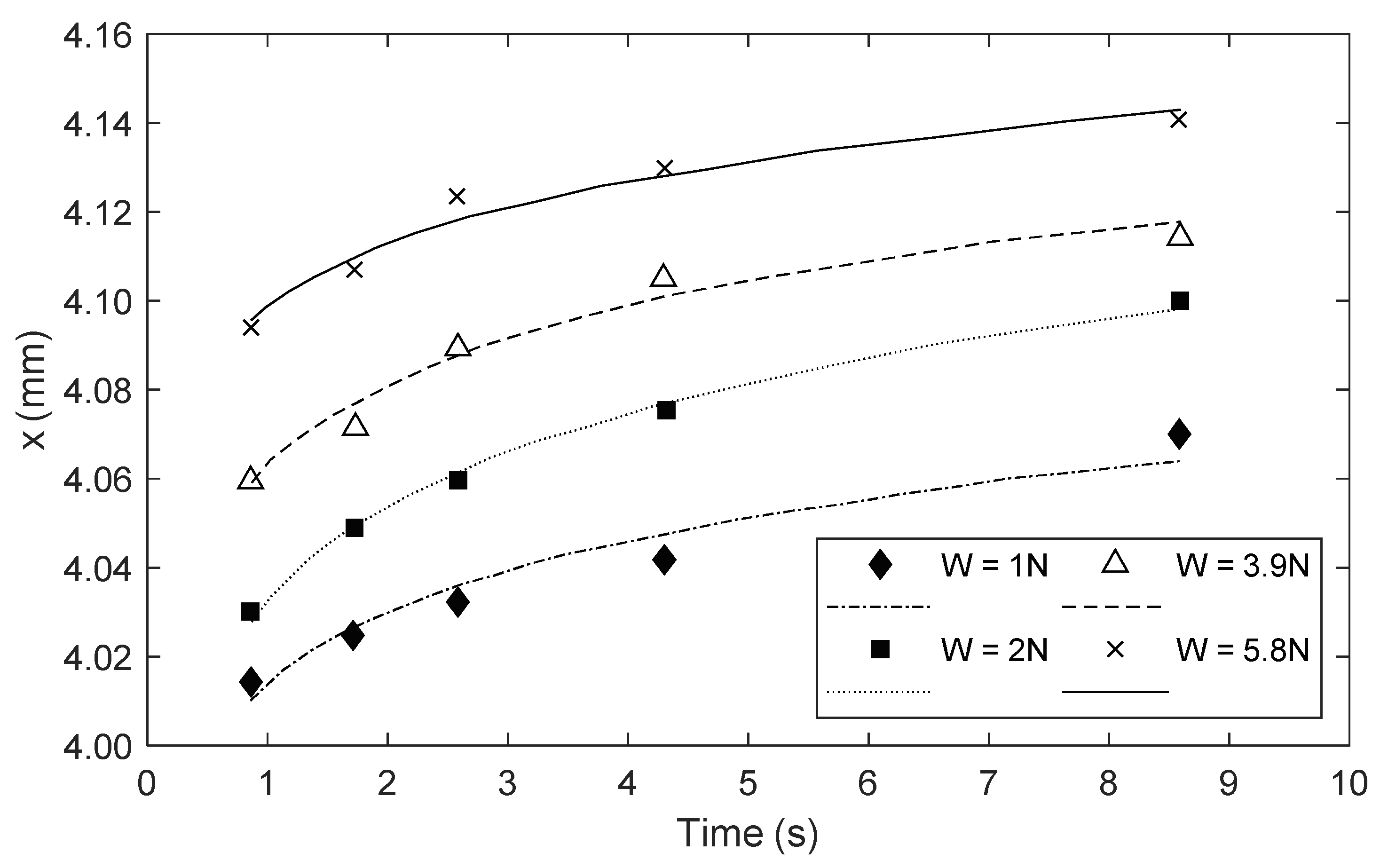
The corresponding growth in the contact area for the same loads is shown in Figure 6. Note that the initial growth in the contact area is faster at higher loads and flattens more rapidly to a steady state value thereafter.

5. Finite Element Analysis of Layered Bonded Viscoelastic Solids

5.1. The Formulation Method

The experimental investigations outlined above can be used to verify the finite element analysis of small strain viscoelastic asymptotic behaviour of soft bonded layers. Here the HFCP layer is modelled as a Maxwell solid.
For small strain linear isotropic viscoelastic isothermal problems, the solution to the following basic hereditary integral [25] is required:
σ ( t ) = 0 t K ( t τ ) ε ( t ) τ d τ + 0 t G ( t τ ) e ( t ) τ d τ
For a combined solution of deviatoric and volumetric stresses the domain is discretised into small finite elements.
The instantaneous moduli: K(τ) and G(τ) are defined as Prony series:
K ( τ ) = K 0 + i = 1 n K i e t τ τ i ,   G ( τ ) = G 0 + i = 1 n G i e t τ τ i
where G 0 and K 0 represent the instantaneous or glassy shear and bulk moduli, and are obtained from:
G 0 = 3 K 0 E 9 K 0 E ,   ϑ = 3 K 0 E 6 K 0
where modulus of elasticity for the HFCP is: E = 1   G P a and Poisson’s ratio, ϑ = 0.4 .
Equation (2) is substituted into Equation (1) and integrated over a finite increment of time:
( d ε d t = Δ ε Δ t ,   d e d t = Δ e Δ   t ) , where the strain components are assumed to vary linearly with τ. Thus, discretisation of Equation (1) provides the constitutive (stress–strain) relationship for the computational element as:
σ = K ( τ ) { ε i = 1 n α i ε i } + G ( τ ) { e j = 1 n β i e i }
where:
α i = K i K ( τ ) , β j = G j G ( τ )
This constitutive (stress–strain) viscoelastic relationship is based on the Maxwell model. It is quite similar to the viscoelastic elements used in some commercial finite element software, such as ABAQUS or ANSYS, with the latter using Visco-88, an eight-noded Maxwell element which is more detailed but computationally more time consuming than the four-noded element used here.
The computational domain is the overall contact patch between the indenter and the sensor structure (i.e., the overall area of the sensor structure shown in Figure 1). Along each of the contact diagonals in Figure 1b, there are 3000 rectangular elements with the constitutive relationship provided by Equation (4). The applied boundary condition is that there are no generated stresses/contact pressures at the edges of the contact patch shown in Figure 1b; σ = 0 . Only compressive stresses (generated contact pressures) are allowed. In practice, tensile stresses can also occur with soft layers (in rebound), usually beyond the sharp edges of the contact. These are ignored in the current analysis. Another assumption made is that no contact separation is allowed. Therefore, the indenter is assumed to be perfectly rigid and smooth. Isothermal conditions and no surface generated friction are also assumed.
The changes in the shear and dilatation creep strains, Δ e j and Δ ε i are obtained as:
Δ φ i = τ i Δ τ ( Δ τ τ i + e τ i Δ τ 1 ) Δ φ + ( 1 e τ i Δ τ ) ( φ n φ i n )
where:
φ i n = ( 1 e Δ τ τ i ) 0 τ n 1 d φ d t d t + e Δ τ τ i 0 τ n 1 ( 1 e ( t τ n 1 ) τ i ) d φ d t d t + Δ φ Δ t τ n 1 τ n ( 1 e ( t τ n ) τ i ) d t
and φ e , ε .
As Δ τ τ i diminishes, the change in the strain components in Equation (5) can be approximated by:
Δ φ i = Δ τ τ i ( 1 2 Δ φ + φ n φ n 1 )
The small changes in the shear and dilatation creep strains are obtained from Equations (5) and (7). The corresponding deviatoric and volumetric stresses are calculated by Equation (4).

5.2. Numerical Prediction and Experiment Verification

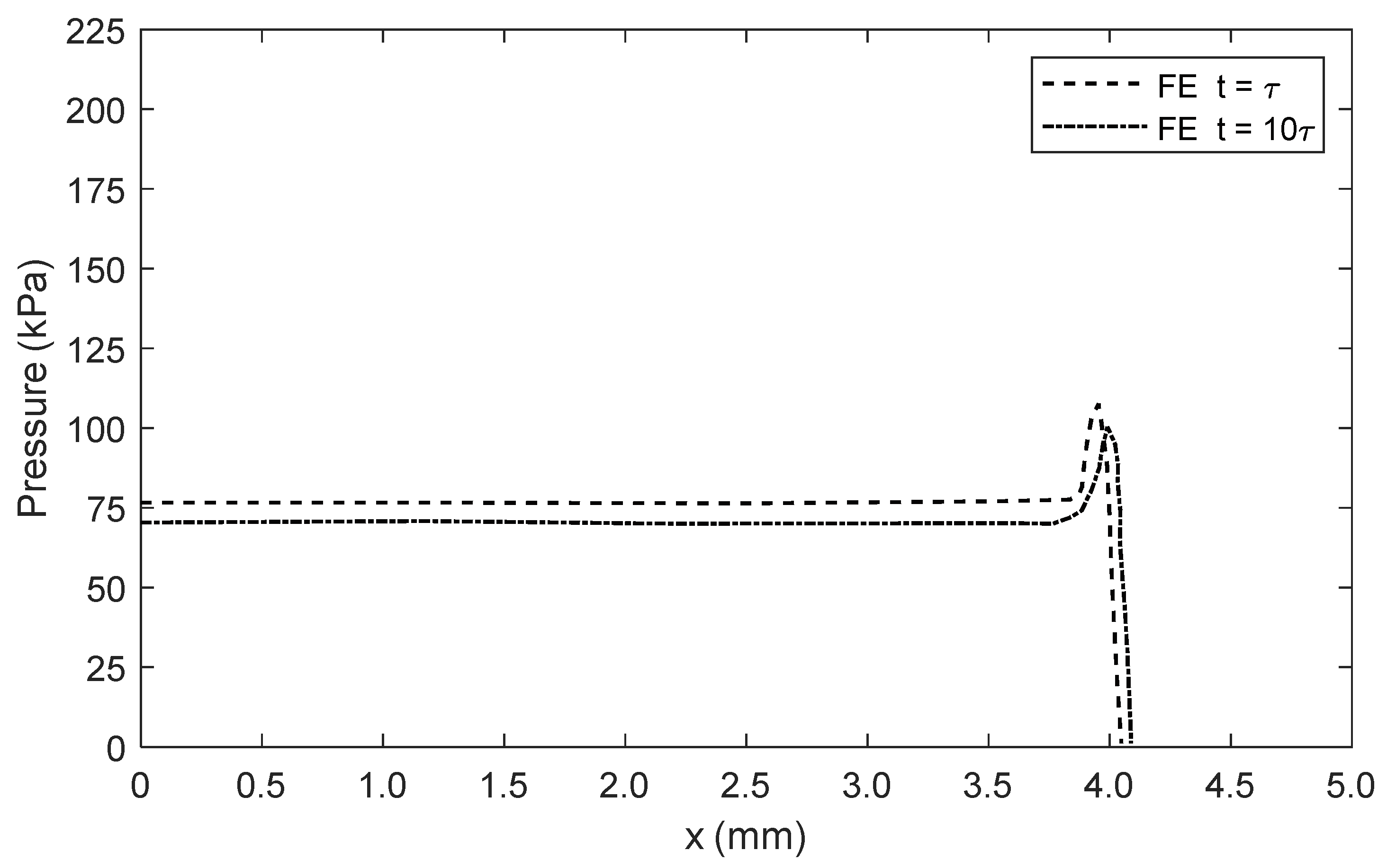
Figure 7 shows the finite element predictions, corresponding to the measured results in Figure 4. The experimental pressure profiles at t = τ and t = 10τ from Figure 4 are shown in Figure 8, along with their corresponding numerical predictions. The predictions and measurements conform very well for the central portion of the pressure distribution (along the x-axis). Good agreement is also obtained between the numerical predictions and the experimental findings for the magnitude of the pressure spike at the contact extremity at t = τ.
Deviation occurs between predicted and measured edge stresses (i.e., pressure spikes) with increasing relaxation. The theoretical value for the pressure spike would tend to infinity for an idealised line contact with increased number of computational elements, as noted by Johnson [6]. Clearly, the measured value would be finite due to the width of the sensing element directly beneath the pressure spike. The finite element value is even less in magnitude because there are an insufficient number of computational nodes in the vicinity of the contact extremities, even though 3000 elements are employed along each of the contact footprint axes, x and y, in the current analysis for the computational domain. The differences between measurements and predictions are due to differences in resolution of the sensing sites and computational finite elements. There is also some small misalignment of the pin contact through minute, but finite, misaligned contact. Furthermore, in practice there is small contact friction irrespective of the efforts made to ensure pure orthogonal loading of the layered sandwich sensor. Nevertheless, remarkable agreement is found between measurements and predictive low modulus viscoelastic finite element analysis, an agreement that has not hitherto been reported in other such studies.

6. Concluding Remarks

A multi-layered bonded sandwich sensor is described with voltage output based on the variation in the conductance of highly filled carbon polymer pieces when subjected to applied load. The output response is proportional to contact pressure distribution which diverges from classical theories, firstly due to the finite line contact geometry when loaded by a flat sharp-ended indenter, and secondly owing to the viscoelastic relaxation of the HFCP. The sensor structure is used to verify the result of a new finite element-based contact mechanics method for viscoelastic layered bonded solids of low elastic moduli. Both the design and development of the multi-layered sandwich sensor and the numerical methodology are original. They show good agreement between measurements and predictions, which has not been shown before, for layered bonded viscoelastic solids which are increasingly used in many applications from robotic tactile sensing to touch sensitive devices, as well as in some traditional applications such as bearings and joints. Such a methodology, as developed and described here, is essential in order to accurately predict the generated contact pressures, which play a key role in inducing sub-surface stresses in the contact layers. These stresses are the determining factors in the structural integrity of contacts [22]. The pressure spikes at the edges of contacts induce localised sub-surface stresses of their own, which can lead to premature failure of contacts as described for some surfaces [26,27]. The method described here should be extended to include the effect of surface friction/traction which is often present in contacts under dynamic conditions [6]. Other important additions could be the inclusion of substrate bending, which can affect the substrate stresses, for which 2D viscoelastic plate models can be used [28].

Author Contributions

Conceptualization, V.V., P.J.-R. and H.R.; Methodology, V.V., P.J.-R. and H.R.; Software, V.V.; Formal analysis, V.V., P.J.-R. and H.R.; Investigation, V.V.; Writing—original draft, V.V., P.J.-R. and H.R.; writing—review and editing, V.V., P.J.-R. and H.R.; Supervision. H.R. All authors have read and agreed to the published version of the manuscript.

Conflicts of Interest

There is no conflict of interest.

Nomenclature

AArea of contact
eVolumetric strain
GModulus of rigidity
iRelaxation time step
KBulk modulus
nIteration step
PPressure
tTime
εShear strain
υPoisson’s ratio
σStress
τRelaxation time
φe or ε
Subscript
0Instantaneous value

References

  1. Thomsen, K.; Klit, P. A study on compliant layers and its influence on dynamic response of a hydrodynamic journal bearing. Tribol. Int. 2011, 44, 1872–1877. [Google Scholar] [CrossRef]
  2. Simmons, G.F.; Varela, A.C.; Santos, I.F.; Glavatskih, S. Dynamic characteristics of polymer faced tilting pad journal bearings. Tribol. Int. 2014, 74, 20–27. [Google Scholar] [CrossRef]
  3. Flitney, B. Advances in understanding of polymer seals for rotating applications. Seal. Technol. 2010, 11, 7–11. [Google Scholar] [CrossRef]
  4. Thomine, M.; Degrange, J.M.; Vigier, G.; Chazeau, L.; Pelletier, J.M.; Kapsa, P.; Guerbe, L.; Dudragne, G. Study of relations between viscoelasticity and tribological behaviour of filled elastomer for lip seal application. Tribol. Int. 2007, 40, 405–411. [Google Scholar] [CrossRef]
  5. Kozuch, E.; Nomikos, P.; Rahmani, R.; Morris, N.; Rahnejat, H. Effect of shaft surface roughness on the performance of radial lip seals. Lubricants 2018, 6, 99. [Google Scholar] [CrossRef] [Green Version]
  6. Johnson, K.L. Contact Mechanics; Cambridge University Press: Cambridge, UK, 1987. [Google Scholar]
  7. Naghieh, G.R.; Rahnejat, H.; Jin, Z.M. Characteristics of frictionless contact of bonded elastic and viscoelastic layered solids. Wear 1999, 232, 243–249. [Google Scholar] [CrossRef]
  8. Hertz, H. On the contact of elastic solids. Z. Reine Angew. Mathematik. 1881, 92, 156–171. [Google Scholar]
  9. Naghieh, G.R.; Jin, Z.M.; Rahnejat, H. Contact characteristics of viscoelastic bonded layers. Appl. Math. Model. 1998, 22, 569–581. [Google Scholar] [CrossRef] [Green Version]
  10. Johns, P.M.; Gohar, R. Roller bearings under radial and eccentric loads. Tribol. Int. 1981, 14, 131–136. [Google Scholar] [CrossRef]
  11. Kushwaha, M.; Rahnejat, H.; Gohar, R. Aligned and misaligned contacts of rollers to races in elastohydrodynamic finite line conjunctions. Proc. Inst. Mech. Eng. Part C J. Mech. Eng. Sci. 2002, 216, 1051–1070. [Google Scholar] [CrossRef] [Green Version]
  12. Kushwaha, M.; Rahnejat, H. Transient elastohydrodynamic lubrication of finite line conjunction of cam to follower concentrated contact. J. Phys. D Appl. Phys. 2002, 35, 2872. [Google Scholar] [CrossRef]
  13. Najjari, M.; Guilbault, R. Edge contact effect on thermal elastohydrodynamic lubrication of finite contact lines. Tribol. Int. 2014, 71, 50–61. [Google Scholar] [CrossRef]
  14. Hultqvist, T.; Shirzadegan, M.; Vrcek, A.; Baubet, Y.; Prakash, B.; Marklund, P.; Larsson, R. Elastohydrodynamic lubrication for the finite line contact under transient loading Conditions. Tribol. Int. 2018, 127, 489–499. [Google Scholar] [CrossRef]
  15. Nambiar, S.; Yeow, J.T. Conductive polymer-based sensors for biomedical applications. Biosens. Bioelectron. 2011, 26, 1825–1832. [Google Scholar] [CrossRef]
  16. Mehdian, M.; Rahnejat, H. Blood flow measurement using a highly filled carbon polymer sandwich sensor and an elasto-pseudo compressible vascular flow. Proc. Inst. Mech. Eng. Part H J. Eng. Med. 1996, 210, 289–296. [Google Scholar] [CrossRef] [Green Version]
  17. Koç, İ.M.; Aksu, C. Tactile sensing of constructional differences in fabrics with a polymeric fingertip. Tribol. Int. 2013, 59, 339–349. [Google Scholar] [CrossRef]
  18. Rahnejat, H.; Bera, H. Sensors, Special purpose. In International Encyclopedia of Robotics; Dorf, R.C., Nof, S.Y., Eds.; John Wiley & Sons Inc.: Hoboken, NJ, USA, 1988; pp. 1536–1544. [Google Scholar]
  19. Sferrazza, C.; Wahlsten, A.; Trueeb, C.; D’Andrea, R. Ground truth force distribution for Learning-based tactile sensing: A finite element approach. IEEE Access 2019, 7, 173438–173449. [Google Scholar] [CrossRef]
  20. Wijesinghe, P.; Sampson, D.D.; Kennedy, B.F. Computational optical palpation: A finite-element approach to micro-scale tactile imaging using a compliant sensor. J. R. Soc. Interface 2017, 14, 20160878. [Google Scholar] [CrossRef]
  21. Conway, H.D.; Lee, H.C.; Bayer, R.G. The impact between a rigid sphere and a thin layer. Trans. ASME J. Appl. Mech. 1970, 37, 159–162. [Google Scholar] [CrossRef]
  22. Teodorescu, M.; Rahnejat, H.; Gohar, R.; Dowson, D. Harmonic decomposition analysis of contact mechanics of bonded layered elastic solids. Appl. Math. Model. 2009, 33, 467–485. [Google Scholar] [CrossRef]
  23. Mehdian, M.; Rahnejat, H. A dexterous anthropomorphic hand for robotic and prosthetic Applications. Robotica 1994, 12, 455–463. [Google Scholar] [CrossRef]
  24. Cutkosky, M.R.; Jourdain, J.M.; Wright, P.K. Skin materials for robotic fingers. In Proceedings of the IEEE International Conference on Robotics and Automation, Raleigh, NC, USA, 31 March–3 April 1987; pp. 1649–1654. [Google Scholar]
  25. Naghieh, G.R.; Rahnejat, H.; Jin, Z.M. Contact mechanics of viscoelastic layered surface. In Computational Methods in Contact Mechanics III; Aliabadi, M.H., Samartin, A., Eds.; WIT Press: Southampton, UK, 1997; pp. 59–68. [Google Scholar]
  26. Kadiric, A.; Sayles, R.S.; Zhou, X.B.; Ioannides, E. A numerical study of the contact mechanics and sub-surface stress effects experienced over a range of machined surface coatings in rough surface contacts. J. Tribol. 2003, 125, 720–730. [Google Scholar] [CrossRef]
  27. Teodorescu, M.; Kushwaha, M.; Rahnejat, H.; Rothberg, S.J. Multi-physics analysis of valve train systems: From system level to microscale interactions. Proc. Inst. Mech. Eng. Part K J. Multi-Body Dyn. 2007, 221, 349–361. [Google Scholar] [CrossRef] [Green Version]
  28. Altenbach, H.; Eremeyev, V.A. On the bending of viscoelastic plates made of polymer foams. Acta Mech. 2009, 204, 137. [Google Scholar] [CrossRef] [Green Version]
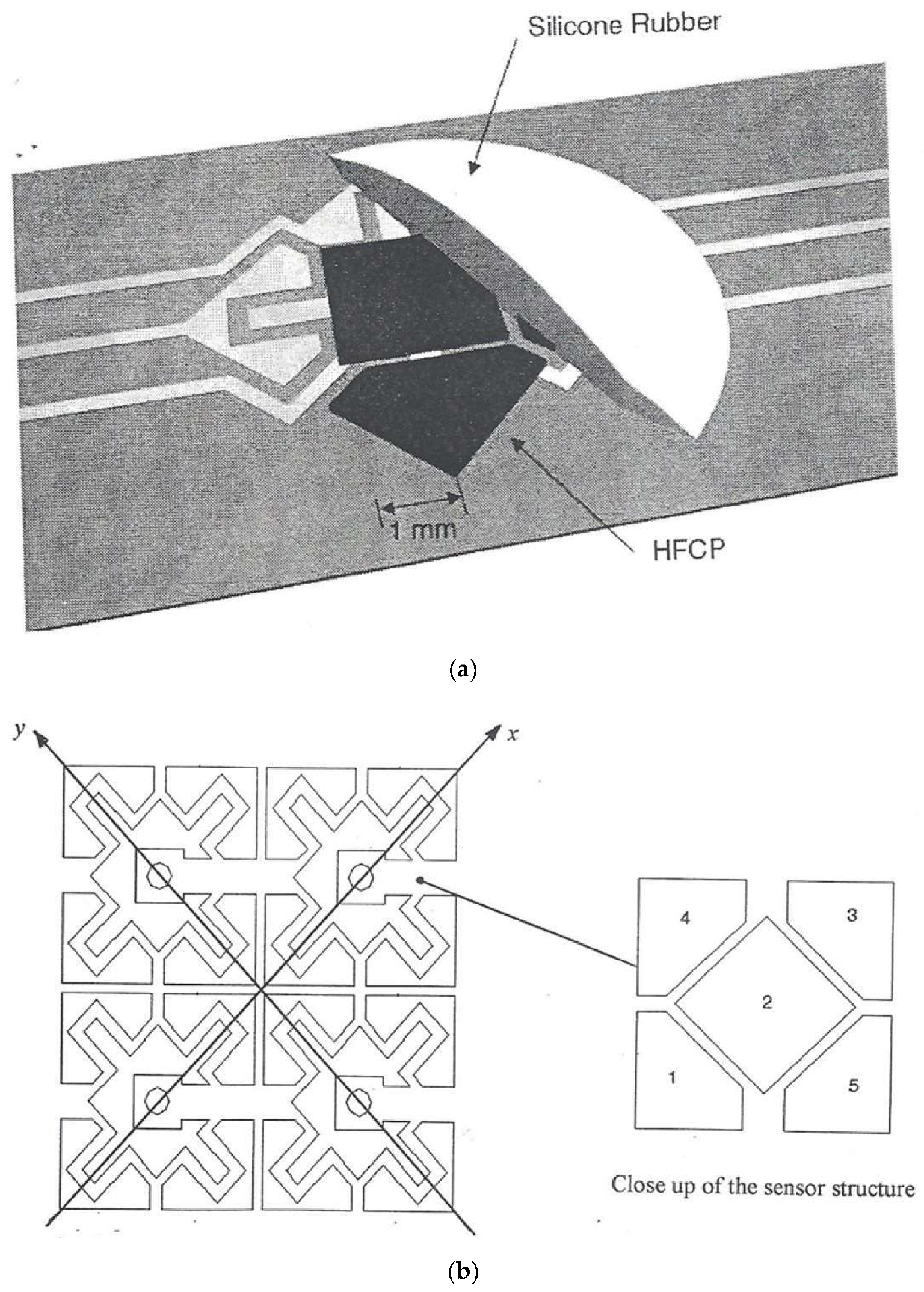
Figure 1. (a) The structure of the artificial skin sensor; (b) the compound sensor used in the indentation tests.
Applsci 10 03363 g001
Figure 2. The indentation test rig.
Applsci 10 03363 g002
Figure 3. The calibration curves for the normal load of 3.9 N.
Applsci 10 03363 g003
Figure 4. Measured axisymmetric contact pressure distribution (normal load of 3.9 N).
Applsci 10 03363 g004
Figure 5. Measured axisymmetric contact pressure distribution (normal load of 5.8 N).
Applsci 10 03363 g005
Figure 6. Growth of contact area with viscoelastic relaxation.
Applsci 10 03363 g006
Figure 7. Predicted contact pressure distribution (normal load of 3.9 N).
Applsci 10 03363 g007
Figure 8. Comparison of predicted and measured contact pressures.
Applsci 10 03363 g008
Table 1. The sensing elements output voltage.
Time (s)Element 1Element 2Element 3Element 4Element 5
τ9.3058.7938.2138.2388.113
9.028.5737.6997.9257.854
8.347.9877.037.246.975
7.9957.6936.756.786.575
10τ7.157.045.896.175.75
Table 2. Measured contact area under different loads.
Relaxation Time (s)Contact Area (mm2)
τ51.785
52.104
52.553
52.939
10τ54.015