Abstract
Two-way relaying channel (TWRC) improves the throughput of one-way relaying channel through network coding at the relay. Time division broadcast (TDBC) is one typical protocol for TWRC, but with three time slots for one round information exchange leading to throughput loss. To enhance throughput performance, incremental redundancy transmission is usually incorporated into TDBC (i.e., TDBC-IR) by one bit feedback, indicating the successful or failed transmission. Nevertheless, TDBC-IR still suffers in throughput since it cannot fully exploit and adapt to the varying channel dynamics. In the paper, we propose a dynamic TDBC protocol with incremental redundancy in the form of rateless coding (i.e., DTDBC-RC) to fully utilizing the varying channel dynamics. In DTDBC-RC, the two sources first transmit in rateless coding way with given maximum allowable transmission time, and then the relay retransmits or not based on its decoding results. To reveal the advantages of DTDBC-RC, we analyze its performance comprehensively in terms of outage probability, expected rate, and diversity-multiplexing trade-off (DMT). We also present a subslot realization scheme for DTDBC-RC (i.e., sub-DTDBC-RC) since the DMT of DTDBC-RC cannot be obtained directly. Simulation and numerical results show the performance advantage of DTDBC-RC (or sub-DTDBC-RC) over TDBC-IR in terms of both expected rate and DMT.
1. Introduction
Two-way relaying is an efficient way to improve the throughput performance of conventional one-way cooperative communications with half-duplex relay [1], where two sources exchange information with the aid of a relay (Considering the scenario where two sources and exchange information with the aid of relay R, four time slots, i.e., the time slots on the , , , and links’ transmission, are typically entailed for one round information exchange between and , leading to throughput loss. To improve throughput performance, two-way relaying is proposed with network coding at R, where both and transmit simultaneously to R, R then network-encodes the information received for and (e.g., through bit level XOR operation) and broadcasts to them, with less time slots.). There are two well-known protocols for two-way decode and forward relaying, i.e., physical-layer network coding (PNC) and time division broadcast protocol (TDBC) [2,3]. For one round information exchange between the two sources, TDBC consumes three time slots, with lower throughput than PNC which only needs two time slots. In this paper, we focus on two-way relaying channel with direct link between the two sources (often encountered in many practical applications) and the TDBC protocol, and aim to improve its throughput.
To enhance throughput performance in relaying channel, incremental redundancy (IR)-based retransmission is commonly used by utilizing one-bit feedback indicating successful or failed decoding at the destination [4,5,6], and it has been incorporated in TDBC (i.e., TDBC-IR) to improve the throughput performance of TDBC [7,8] (Note that one retransmission is used in PNC in [9] to form a new protocol named PNC-IR, aiming to improve the outage performance. However, not only the outage performance but also the throughout performance of PNC-IR are improved by introducing one retransmission when compared with PNC.).
Although IR can improve throughput, we argue that TDBC-IR is not the best way since fixed two or three time slots are still entailed, leading to underutilizing good channel conditions (or unable to adapt to the varying channel dynamics). Motivated by rateless coding, which adapts to varying channel dynamics and achieves (or approaches) channel capacity automatically [10], we propose a dynamic TDBC with rateless coding as a kind of incremental redundancy transmission (termed DTDBC-RC for short). In DTDBC-RC, the two sources first transmit with a given maximum allowable transmission time, and then the relay retransmits or not based on the decoding results. To reveal the advantages of DTDBC-RC, we analyze its performance comprehensively in terms of outage probability, expected rate, and diversity-multiplexing trade-off (DMT). We also present a subslot realization scheme for DTDBC-RC (i.e., sub-DTDBC-RC) for the DMT derivation of DTDBC-RC since it cannot be obtained directly based on conventional outage probability and expected rate analysis. It is revealed that although TDBC-IR and DTDBC-RC have the same outage performance, the latter outperforms the former in both expected rate and DMT performance.
The rest of the paper is organized as follows. Section 2 first presents the system models of DTDBC-RC and sub-DTDBC-RC. Their performance is then analyzed in Section 3 while simulation and numerical results are shown in Section 4. Finally, conclusions are drawn in Section 5.
Notation: is the logarithm function with base 2. is the probability of a random event. . is exponential equality and means that . Accordingly, means ‘exponentially larger or equal than’, i.e., means . means complex Gaussian distribution with mean a and variance b. denotes the function ’s value at .
2. System Models
2.1. System Model of DTDBC-RC
Considering a delay-constrained transmission application with two sources (denoted by and ) exchanging information with the aid of a relay (denoted by R), one-round information exchange with maximum allowable transmission time T consists of at most three time slots and each source’s message is transmitted for at most two time slots (i.e., one time slot for its own transmission and the other for the relay). The first and second time slots are with maximum allowable transmission time , and the third time slot is with minimum transmission time , where if retransmission at the third time slot is possible. The message is transmitted in the form of codeword. For simplicity of analysis and without loss of generality, it is assumed that both sources transmit with the same rate and the same power (When the scenario with different data rates and/or different power is considered, the transmission lengths of each time slot in DTDBC-RC are different although with channel reciprocity assumption (see the system model in Section 2). This is a general scenario which can be extended directly from the simple scenario with same data rates and same power in the paper. Moreover, the performance analysis in Section 3 can be directly applied to the general scenario. Since the simple scenario captures the essence of utilizing the dynamics of the direct link transmission by rateless coding, we do not consider the general scenario here.). The channels keep unchanged in one-round information exchange and changes independently across different rounds. Moreover, the channels between any two nodes are assumed to be reciprocal.
The codeword lengths of and corresponding to the two-time-slot transmission are denoted by and , i.e., the transmitted codewords of and are denoted by and , respectively. The proposed DTDBC-RC protocol works in the following way.
In the first time slot (with given maximum allowable transmission time ), broadcasts its first part of codeword (i.e., ) continuously to and R in the rateless coding way. decodes the received message before or until . If decodes successfully, it feeds back one-bit acknowledgement (ACK). If cannot decode successfully until , it feeds back one-bit non-acknowledgement (NACK). In the second time slot (also with given maximum allowable transmission time ), works in the same way as in the first time slot, i.e., it broadcasts the first part of codeword (i.e., ) continuously to and R in the rateless coding way. Due to channel reciprocity, has the same decoding results as , and it feeds back NACK or ACK accordingly.
After the first two time slots, the following working process of DTDBC-RC depends on the decoding results of both and , and there are only two decoding states listed as follows.
State 1: both and cannot decode successfully. In this state, depending on the decoding result at R, there are two cases. In Case I, R successfully decodes the messages from both and . It feeds backs an ACK to both and , re-encodes the received message from both sources and network-encodes the two sources’ message before retransmission (e.g., through bit-level XOR operation), and retransmits the network-encoded message to both and in the third time slot (i.e., until the transmission length T is reached). In this case, () decodes ’s (’s) message by combining the message received from both () in the first time slot and from R in the third time slot. In Case II, at least one source’s message ( or ) cannot be decoded successfully at R. In this case, R feeds back a NACK and there is no retransmission occurred at , , or R. Thus, an outage event occurs and and begin a new round of information exchange as described above (In TWRC, outage probability is usually defined for the whole system, not for any single source (see [2,3] and the references therein). In the paper, we also define the system outage probability. Therefore, if R cannot decode successfully any source’s message, there is no improvement in system outage probability if or retransmits in the third time slot. Thus, there is no need to assume retransmission in the third time slot if at least one source’s message cannot be decoded successfully at R.).
State 2: both and decode successfully. In this state, and feed back ACKs to each other and begin a new round of information exchange, as described above.
The above two states are depicted in Figure 1, where is the transmission length of the first and second time slots (it will be calculated in Section 3) due to the channel reciprocity assumption.
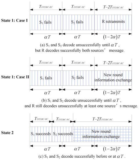
Figure 1.
The working states of the dynamic time division broadcast rateless coding (DTDBC-RC) protocol.
Note that (i) the one-bit ACK/NACK feedback is assumed to be received without delay or error, e.g., through a dedicated control channel; (ii) in one-round information exchange of DTDBC-RC, there are at most three time slots and two time slots for the whole system and for each source, respectively. Moreover, the transmission lengths of the first and second time slots are random depending on the channel quality of the direct link because the sources transmit in rateless coding way. Therefore, the transmission length of one-round information exchange is when both and succeed in the first and second time slots (corresponding to State 2) or when R cannot decode successfully at least one source’s message (corresponding to Case II in State 1), or is T when both and cannot decode successfully in the first and second time slots and R successfully decodes both sources’ messages (corresponding to Case I in State 1); and (iii) we extend the equal-length time slot assumption in [7,8] to the case with unequal-length time slot in the paper (see Figure 1), i.e., both the first and second time slots are with length in TDBC-IR like DTDBC-RC (The protocol in [7,8] corresponds to the case when for TDBC-IR in the paper.). Thus, the outage probability, expected rate, and DMT analysis for TDBC-IR in Section 3 is for the unequal-time length case.
2.2. System Model of Sub-DTDBC-RC
With the same assumptions as in DTDBC-RC, we present a subslot implementation scheme for DTDBC-RC (i.e., sub-DTDBC-RC) since its DMT cannot be derived directly based on conventional outage and expected rate analysis (this will be detailed in Section 3). In sub-DTDBC-RC, the maximum allowable transmission time at the first and second time slots is divided into N equal-length subslots, each with length . The sub-DTDBC-RC works in the same way as DTDBC-RC, with the exception that () only decodes at one subslot before or at in the former (i.e., at the n-th subslot, where ), whereas it decodes at any time before or at for the latter. The working process of sub-DTDBC-RC is shown in Figure 2.
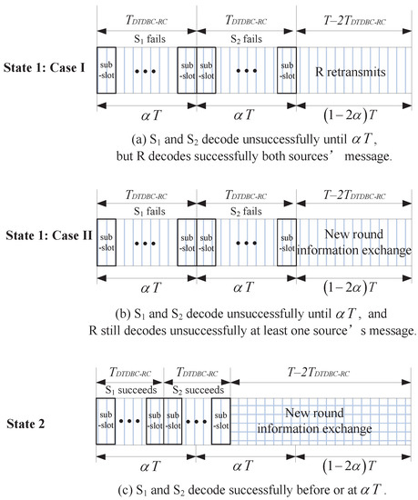
Figure 2.
The working states of the sub-DTDBC-RC protocol.
With the above description, it is intuitively and readily seen that when , the sub-DTDBC-RC becomes DTDBC-RC.
Remark 1: We note that the authors in [11] proposed a similar protocol as TDBC. Their protocol works in the same way as TDBC protocol with direct link, but , , and R transmit in the rateless coding way, where there are always three time slots and the lengths of three time slots are all random depending on the channels of direct and relaying links. The major differences between DTDBC-RC and the protocol in [11] are that (i) only R decodes in the first and second time slots while and keep silent (leading to three-time-slot transmission) in the latter, while in the former, and decode and R only retransmits when possible (leading to possible two-time-slot transmission); (ii) DTDBC-RC applies in the delay-constrained scenarios with given maximum allowable transmission time for one round information exchange while the latter applies in the scenarios with no delay-constraint; and (iii) we investigate the performance in terms of outage probability, expected rate, and DMT in the paper, which is more comprehensive than the performance analysis in [11] (The performance analysis method in Section 3 can be directly extended to the protocol in [11], where the two sources transmit with different data rates.).
From the above description, it is also intuitive that DTDBC-RC will be more efficient in throughput than the protocol in [11]. We also point out that the protocol in [11] will never have an outage event occurring since no time delay constraint is entailed, therefore its performance is not compared with the protocols presented in this paper.
3. Performance Analysis
Let denote the channel coefficient of the link and denote the channel gain power, where and . With channel reciprocity assumption, we have and . Moreover, assume that (i) all channels (i.e., , , and ) are independent with distribution , , and , respectively; (ii) all the noises at the corresponding receiving nodes are independently and identically distributed (i.i.d.) complex additive white Gaussian noises with distribution ; (iii) all nodes transmit with power ; (iv) each codeword of the two sources bears M bits information and then the target data rate for each source is bits/s/Hz, where W is the transmission bandwidth of the system; and (v) ideal capacity approaching rateless coding is adopted.
With the above assumptions, the transmission length of the first or second time slot of DTDBC-RC is expressed as , a random variable depending on the channel quality of the direct link (with being the transmit signal-to-noise ratio (SNR). (The transmit SNR is defined as the ratio between the transmit power and the channel noise power, and it is usually used in performance analysis although it is not an important metric in practice.)).
3.1. Outage Probability and Expected Rate
With the system model description in Section 2, the outage probability of DTDBC-RC, defined as the probability that the system cannot support the give target data rate (i.e., the probability that either source cannot support the the give target data rate), is presented in the following theorem.
Theorem 1.
For given target data rate C bits/s/Hz, the outage probability of DTDBC-RC is
where , , and are expressed as
and
with, , , , , and the integrand
Proof.
Let ( be the event that the link is in outage after the i-th time slot () transmission, and let be its complementary event. Then, for the target data rate C bits/s/Hz, according to the total probability formula, the outage probability of DTDBC-RC is
where (with and ) is the event that the source j still cannot decode successfully after combining the messages received from both the source i and the relay R, i.e.,
and
With the identity (for any set A, B, and C)
the first and second terms at the right-hand side (RHS) of Equation (5) can then be calculated as
and
In the following, we calculate , , and at the RHS of . The calculation of can be divided into two cases: (i) when , we have , then ; (ii) when , we have and the integral area for and is . Thus,
From the above results, we see when , . This means that when the transmission of the link fails in the first time slot and the link succeeds in the second time slot, then the transmission of ’s message aided by will be successful. The reason is that the link (and thus, the link with the channel reciprocity assumption) can support the message transmission without outage.In a similar way, can be calculated as in Equation (3), whose calculation process is omitted here.As for , its integral area is the intersection of and , thus only when and its integral area is . Then,
Substituting the above results into Equation (5), we obtain the result, i.e., Equation (1) in the theorem. □
Remark 2:
It is worthwhile to point out that DTDBC-RC has the same outage probability as that of TDBC-IR and sub-DTDBC-RC for fixed target data rate. This can be deduced by how the outage event occurs. We also note that for TDBC-IR in [7,8], the authors consider the case with three equal-length time slots.
With the outage probability given in Theorem 1, the expected rate—defined as the expected successfully transmitted throughput—of DTDBC-RC is expressed as (according to the total probability formula)
where and at the RHS denote the expected rates corresponding to State 2 and State 1, respectively, and is the channel gain power when (or ) decodes successfully exactly at .
Similarly, the expected rates of TDBC-IR and sub-DTDBC-RC are derived as follows for comparison with DTDBC-RC.
where is the outage probability of the direct link transmission in TDBC-IR and ; , is the outage probability for or in sub-DTDBC-RC that the direct link fails after the i-th () time slot transmission (i.e., ), and is the probability that or exactly fails after the i-th time slot but succeeds after the -th time slot transmission.
3.2. Diversity-Multiplexing Trade-off
For the DMT derivation, we first present its definition and two related lemmas.
Definition 1
(of DMT [12,13]). Consider a family of codes operating at SNR ρ with rate bits/s/Hz. If is the outage probability of the protocol for rate , the multiplexing gain r and the diversity gain d are defined as and , respectively.
The DMT metric takes into account both transmission reliability and throughput performance simultaneously and provides a more comprehensive view on the performance of communications systems. Note that when calculating DMTs of different protocols, the target data rate C scales with in different forms (see in the following subsections).
Lemma 1
([13]). If h is a complex Gaussian random variable with zero mean and given variance, let , then the probability density function of v is given by .
Lemma 2
([13]). For independent random variables distributed identically with v, the probability that belongs to the set Θ is characterized by with , where is the set consisting of only non-negative elements of the set Θ.
3.2.1. DMT of TDBC-IR
For TDBC-IR, its DMT is presented in the following theorem for comparison.
Theorem 2.
The DMT of TDBC-IR is given as: (i) when ,
(ii) when,
Proof.
Since in Equation (5) is decided by and , to prove the theorem, we first calculate and then with C expressed as the function of the multiplexing gain and when .
Calculation of . When , , based on Equation (10). Let , and , then according to Lemma 1, u, v, and w are i.i.d. random variables with identical probability density function with . Let , where r () is the multiplexing gain of TDBC-IR, then and we have (based on Equations (5) and (6))
where the exponential equality holds because . Then, by substituting , and into Equation (14), we have
where the second exponential equality is derived based on Lemma 2.
Calculation of . Based on Equations (14) and (8), we have and then
With this equation, , we only need to calculate to obtain , and then . The following process calculates .
First, when , (see from Equations (2)–(4)) and then ; second, when ,
Let , then is the solution of the following optimization problem based on Lemma 2.
Since , . To obtain , we only need to compare with 1.
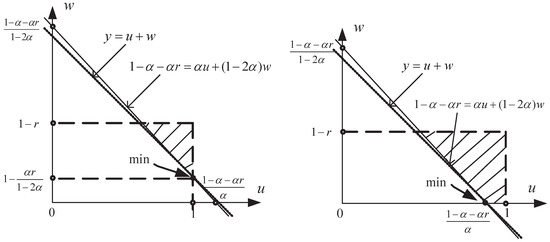
Case I: when , and with (see the left part of Figure 3 for calculation of , which is a simple linear programming problem).
Figure 3.
The calculation of .
Case II: when , and with (see the right part of Figure 3 for calculation of ).
Concluding the above process, we have
- (i)
- when , ;
- (ii)
- when , for ,For , ;
- (iii)
- when , for ,For , .
With the above results, the DMT of TDBC-IR, i.e., , is readily obtained by comparing and . □
3.2.2. DMT of Sub-DTDBC-RC and DTDBC-RC
When , it is impossible to obtain the limit value of the expected rate of DTDBC-RC from Equation (9), and the DMT of DTDBC-RC cannot be obtained with the conventional outage and expected rate analysis like in Section 3.2.1. Hence, we first derive the DMT of sub-DTDBC-RC and then the DMT of DTDBC-RC by setting the number of subslots .
As for the DMT of sub-DTDBC-RC, it is given in the following theorem.
Theorem 3.
The DMT of sub-DTDBC-RC is
where N is the number of subslots of sub-DTDBC-RC.
Proof.
When , we have from Equation (11). Let , where r () is the multiplexing gain of sub-DTDBC-RC, . Then, and of in Equation (5) are calculated as follows.
Calculation of . The calculation of follows the same way as in the proof of Theorem 2, only with the exception that C is now replaced by . Substituting C into Equation (14),
Calculation of . Following the same way as in the proof of Theorem 2, only is needed for calculation of and then (since ). First, when , ; when , substituting into in Equation (8), we get , where is the solution of the following optimization problem based on Lemma 2.
Moreover, (since ). Thus, to calculate , we only need to compare with 1.
Case I: when , , and with .
Case II: when , and with .
The calculation of , which follows the same way as for calculating in the proof of Theorem 2, is simple and thus omitted here.
Concluding the above process, we have (i) when , ; (ii) when ,
(iii) and when , .
With the above results, the DMT of sub-DTDBC-RC, i.e., , is readily obtained by comparing and . □
With Theorem 3, the DMT of DTDBC-RC is readily obtained by setting as follows.
Corollary 1.
The DMT of DTDBC-RC is , i.e., its diversity gain is always two for any multiplexing gain r (), independent of α.
Proof.
By setting in Equation (17), the result is obtained directly. □
4. Simulation and Numerical Results
In the section, Matlab is used for simulation and the simulation process proceeds as described in Section 2. The simulation parameters are set as follows: bits/s/Hz, , and the number of information exchange rounds is . In the simulation process, all the channel coefficients are produced independently and keep unchanged in each round of information exchange. Moreover, if the channels in the DTDBC-RC (or sub-DTDBC-RC) protocol cannot support the target rate, an outage event occurs.
The theoretical (Equation (1)) and simulated outage probabilities of DTDBC-RC/TDBC-IR are presented in Figure 4 for various , where the horizontal axis denotes the transmit SNR (the SNR has the same meaning for the other figures in the paper). From the figure, we see the theoretical and simulated outage probabilities coincide exactly, validating the results in Theorem 1. Moreover, when , the outage performance becomes better as increases. Based on the result of [14] (i.e., the result in Figure 10 of [14]), the optimal cooperation level (i.e., the ratio of a codeword between the part transmitted by the source and that transmitted by the relay) in reaching the best outage performance for one-way coded cooperation lies between 0.6 and 0.7 when the direct and relaying channels are with the same distribution. For DTDBC-RC/TDBC-IR, when = 0.4, it corresponds to the cooperation level , which lies between 0.6 and 0.7; when = 0.45, it corresponds to the cooperation level (larger than 0.7). Thus, the outage performance of DTDBC-RC/TDBC-IR when = 0.4 is better than that of = 0.45.
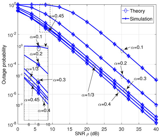
Figure 4.
The outage probability performance of the DTDBC-RC/TDBC-IR protocol for various .
The expected rate performance corresponding to Figure 4 for TDBC-IR and DTDBC-RC is shown in Figure 5 and Figure 6, respectively. Figure 5 reveals that on the one hand, the expected rate of TDBC-IR at low-SNR region (when dB) becomes larger as increases. This is because its expected rate is mainly decided by the second term on the RHS of Equation (10) at this SNR region, i.e., the expected rate decided by the third-time-slot transmission dominates. On the other hand, its expected rate becomes larger as decreases at high-SNR region (when dB). This is because its expected rate is mainly decided by the first term on the RHS of Equation (10) at this SNR region, i.e., the expected rate decided by the first two-time-slot transmission dominates. Moreover, as SNR tends to infinity, the expected rate of TDBC-RC reaches (i.e., the first term on the RHS of Equation (10)) since .
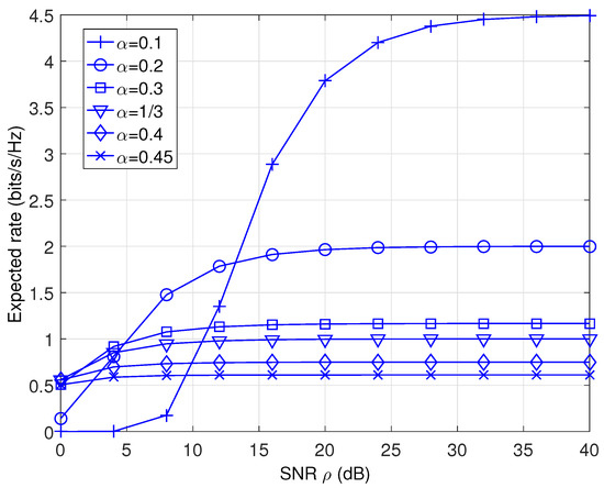
Figure 5.
The expected rate performance of the TDBC-IR protocol.
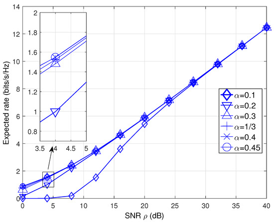
Figure 6.
The expected rate comparison performance of the DTDBC-RC protocol.
For DTDBC-RC, the similar expected rate performance trend is observed at low-SNR region (see Figure 6), i.e., the expected rate becomes larger as increases. The reason is also similar, i.e., it is mainly decided by the second term (i.e., ) on the RHS of Equation (9) and thus, the expected rate decided by the third-time-slot transmission dominates. However, when the SNR is large enough, its expected rate is independent of (unlike for the TDBC-IR) and becomes infinite as SNR tends to infinity. This is because the expected rate of DTDBC-RC is mainly decided by the first term at the RHS of Equation (9) (i.e., ) and it will always succeed in the first two-time-slot transmission (thus, its transmission time only depends on the channel distribution of the direct link).
The expected rate performance comparison among TDBC-IR, DTDBC-RC, and sub-DTDBC-RC (with various number of subslots N) is presented in Figure 7. We see that DTDBC-RC outperforms sub-DTDBC-RC and sub-DTDBC-RC outperforms TDBC-IR, revealing the expected rate performance advantage of DTDBC-RC (or sub-DTDBC-RC) over TDBC-IR. Moreover, as N increases the expected rate performance of sub-DTDBC-RC approaches that of DTDBC-RC gradually, validating the intuition that sub-DTDBC-RC becomes DTDBC-RC as .
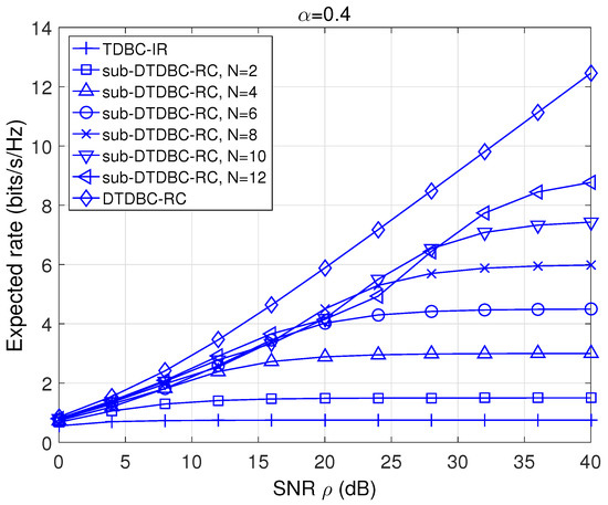
Figure 7.
The expected rate comparison of TDBC-IR, DTDBC-RC, and sub-DTDBC-RC.
As for the DMT performance, we plot the DMTs of TDBC, DTDBC-RC, and sub-DTDBC-RC in Figure 8 based on the results in Theorem 2, Theorem 3, and the Corollary. We see that DTDBC-RC outperforms sub-DTDBC-RC and sub-DTDBC-RC outperforms TDBC-IR for the same . It is also obtained from Theorem 2 that TDBC-IR achieves its best DMT performance when .
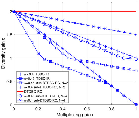
Figure 8.
The diversity-multiplexing trade-off (DMT) performance comparison of TDBC-IR, DTDBC-RC, and sub-DTDBC-RC.
5. Conclusions
In this paper, we considered a two-way relaying channel with direct link and proposed the DTDBC-RC protocol to fully utilize the channel dynamics of the direct link by using rateless coding. We analyzed the performance (in terms of outage probability, expected rate, and DMT) of DTDBC-RC and presented a subslot implementation scheme (sub-DTDBC-RC) to derive the DMT of DTDBC-RC. Compared with the already existing TDBC-IR protocol, DTDBC-RC (or sub-DTDBC-RC) has better expected rate and DMT performance.
Author Contributions
K.X. and Z.D. conceived of and designed the model, performed the theoretical analysis and simulation, analyzed the simulation result, and wrote the paper. M.G., C.Y., and B.J. provided valuable suggestions for this paper and helped in simulation and writing. All authors have read and agreed to the published version of the manuscript.
Funding
This work is supported by the National Natural Science Foundation of China under Grant No. 61801492 and No. 61601490, and is also supported by research fund of National University of Defense Technology with contract No. ZK18-03-20.
Conflicts of Interest
The authors declare no conflict of interest.
References
- Rankov, B.; Wittneben, A. Spectral efficient protocols for half-duplex fading relay channels. IEEE J. Sel. Areas Commun. 2007, 25, 379–389. [Google Scholar] [CrossRef]
- Liu, P.; Kim, I.M. Performance analysis of bidirectional communication protocols based on decode-and-forward relaying. IEEE Trans. Commun. 2010, 58, 2683–2696. [Google Scholar] [CrossRef]
- Kim, S.J.; Mitran, P.; Tarokh, V. Performance bounds for bidirectional coded cooperation protocols. IEEE Trans. Inf. Theory 2008, 54, 5235–5241. [Google Scholar] [CrossRef]
- Laneman, N.J.; Tse, D.N.; Wornell, G.W. Cooperative diversity in wireless networks: Efficient protocols and outage behavior. IEEE Trans. Inf. Theory 2004, 50, 3062–3080. [Google Scholar] [CrossRef]
- Yang, Y.; Chen, W.; Li, O.; Liu, Q.; Hanzo, L. Truncated-ARQ aided adaptive network coding for cooperative two-way relaying networks: Cross-layer design and analysis. IEEE Access 2016, 4, 9361–9376. [Google Scholar] [CrossRef]
- He, J.; Liew, S.-C. ARQ for physical-layer network coding. IEEE Trans. Mob. Comput. 2016, 15, 1614–1631. [Google Scholar] [CrossRef]
- Xu, K.; Gao, Y.; Yi, X.; Zang, G.; Sha, N. Performance analysis of time division broadcast protocol with incremental relaying and symmetric users. Int. J. Commun. Syst. 2013, 26, 1419–1432. [Google Scholar] [CrossRef]
- Ding, H.; Ge, J.; da Costa, D.B.; Jiang, Z. Two birds with one stone: Exploiting direct links for multiuser two-way relaying systems. IEEE Trans. Wirel. Commun. 2012, 11, 54–59. [Google Scholar] [CrossRef]
- Xu, K.; Gao, Y.; Xu, Y.; Fan, Z.; Yi, X. Decode-and-forward two-way relaying protocol with one retransmission. Int. J. Commun. Syst. 2014, 27, 776–793. [Google Scholar] [CrossRef]
- Castura, J.; Mao, Y. Rateless coding for wireless relay channel. IEEE Trans. Wirel. Commun. 2007, 6, 1638–1642. [Google Scholar] [CrossRef]
- Yu, Z.; Zhang, Z.; Yin, R.; Yu, G.; Wang, W. Joint network-channel coding with rateless code in two-way relay systems. IEEE Trans. Wirel. Commun. 2013, 7, 3158–3169. [Google Scholar]
- Zheng, L.; Tse, D. Diversity and multiplexing: A fundamental tradeoff in multiple-antenna channels. IEEE Trans. Inf. Theory 2003, 49, 1073–1096. [Google Scholar] [CrossRef]
- Azarian, K.; Gamal, H.E.; Schniter, P. On the achievable diversity-multiplexing tradeoff in half-duplex cooperative channels. IEEE Trans. Inf. Theory 2005, 51, 4152–4172. [Google Scholar] [CrossRef]
- Hunter, T.E.; Sanayei, S.; Nosratinia, A. Outage analysis of coded cooperation. IEEE Trans. Inf. Theory 2006, 52, 375–391. [Google Scholar] [CrossRef]
© 2019 by the authors. Licensee MDPI, Basel, Switzerland. This article is an open access article distributed under the terms and conditions of the Creative Commons Attribution (CC BY) license (http://creativecommons.org/licenses/by/4.0/).