A Review on Laser Powder Bed Fusion of Inconel 625 Nickel-Based Alloy

 ,
,  , , , and
Abstract
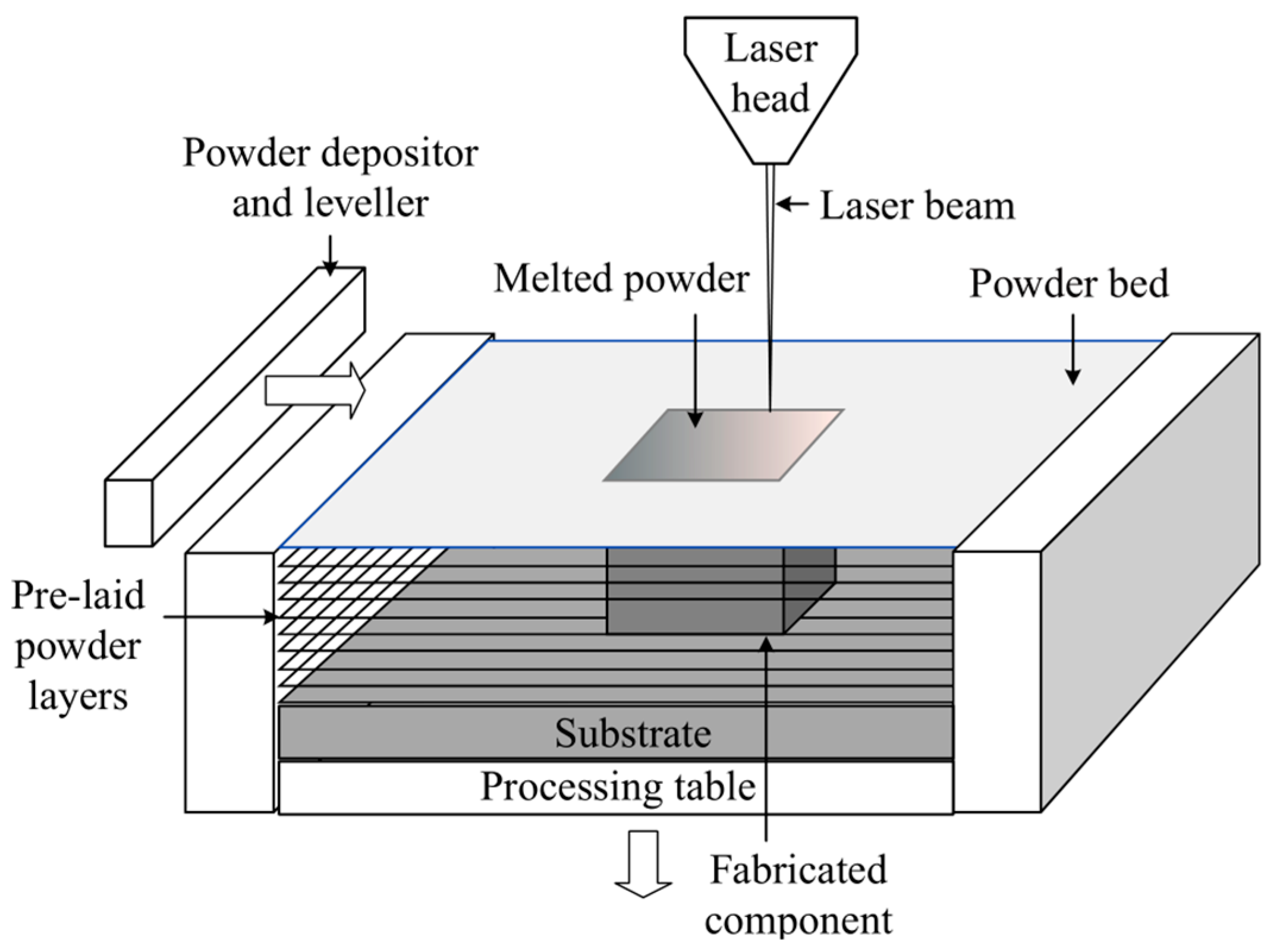
1. Introduction
2. Macroscopic Characteristics of Samples
3. Microstructure
3.1. Microstructure in As-Built State
3.2. Microstructure After Heat Treatments
4. Residual Stresses and Distortion
5. Defects
6. Mechanical Properties
6.1. Hardness Distribution
6.2. Tensile Strength
6.3. Other Properties
7. Summary and Outlook
- (1)
- Characterize the macroscopic defects and microstructure of as-built and post-treated IN625 alloy to deeply explore the formation mechanism of macroscopic defects (pores, microcracks, balling, un-melted zone) and the microstructure evolution mechanism (grain boundary, second-phase, dislocation, subgrain boundary, stacking fault, etc.).
- (2)
- Study the anisotropy and site-specific features of high and low-temperature performance (strength, fatigue, creep, corrosion, etc.) of LPBF IN625 alloy and clarify the reasons, especially the influence of macro anisotropy and microstructure anisotropy at the as-built and post-treated states on the above-mentioned properties.
- (3)
- Establish models to predict the microstructure evolution and residual stress distribution of LPBF IN625 alloy, i.e., building the relationship between LPBF parameters, microstructure, residual stress, and mechanical properties.
Author Contributions
Funding
Acknowledgments
Conflicts of Interest
References
- Lu, B.H.; Li, D.C. Development of the additive manufacturing (3D printing) technology. Mach. Build. Autom. 2013, 42, 1–4. [Google Scholar]
- Huang, Y.; Leu, M.C.; Mazumder, J.; Donmez, A. Additive Manufacturing: current state, future potential, gaps and needs, and recommendations. J. Manuf. Sci. Eng. 2015, 137, 014001. [Google Scholar] [CrossRef]
- Li, H.L.; Jia, D.C.; Yang, Z.H.; Duan, X.M.; Cai, D.L.; Zhou, Y. Research progress on selective laser melting 3D printing of titanium alloys and titanium matrix composites. Mater. Sci. Technol. 2019, 27, 1–15. [Google Scholar]
- Chen, L.; He, Y.; Yang, Y.X.; Ren, H.T. The research status and development trend of additive manufacturing technology. Int. J. Adv. Manuf. Technol. 2016, 89, 3651–3660. [Google Scholar] [CrossRef]
- Gibson, I.; Rosen, D.; Stucker, B. Additive Manufacturing Technologies: 3D Printing, Rapid Prototyping, and Direct Digital Manufacturing; Springer: New York, NY, USA, 2010; ISBN 978-1-4939-2112-6. [Google Scholar]
- Erhard, B.; Ulrike, H.; Vitus, H.; Damien, B. Additive manufactured AlSi10Mg samples using selective laser melting (SLM): microstructure, high cycle fatigue, and fracture behavior. Mater. Des. 2012, 34, 159–169. [Google Scholar]
- Zhang, B.C.; Liao, H.L.; Christian, C. Effects of processing parameters on properties of selective laser melting Mg–9%Al powder mixture. Mater. Des. 2012, 34, 753–758. [Google Scholar] [CrossRef]
- Vaezi, M.; Seitz, H.; Yang, S.F. A review on 3D micro-additive manufacturing technologies. Int. J. Adv. Manuf. Tech. 2013, 67, 1721–1754. [Google Scholar] [CrossRef]
- Poulin, J.R.; Brailovski, V.; Terriault, P. Long fatigue crack propagation behavior of Inconel 625 processed by laser powder bed fusion: influence of build orientation and post-processing conditions. Int. J. Fatigue 2018, 116, 364–647. [Google Scholar] [CrossRef]
- Gao, W.; Zhang, Y.B.; Ramanujan, D.; Ramani, K.; Chen, Y. The status, challenges, and future of additive manufacturing in engineering. Comput. Aided Des. 2015, 69, 65–89. [Google Scholar] [CrossRef]
- Rochus, P.; Plesseria, J.Y.; Elsen, M.V.; Kruth, J.P.; Carrus, R.; Dormal, T. New applications of rapid prototyping and rapid manufacturing (RP/RM) technologies for space instrumentation. Acta Astronaut. 2007, 61, 352–359. [Google Scholar] [CrossRef]
- Criales, L.E.; Arısoy, Y.M.; Özel, T. Sensitivity analysis of material and process parameters in finite element modeling of selective laser melting of Inconel 625. Int. J. Adv. Manuf. Tech. 2016, 86, 2653–2666. [Google Scholar] [CrossRef]
- Rashid, R.; Masood, S.H.; Ruan, D.; Palanisamy, S.; Rahman Rashid, R.A.; Brandt, M. Effect of scan strategy on density and metallurgical properties of 17-4PH parts printed by Selective Laser Melting (SLM). J. Mater. Sci. Technol. 2017, 249, 502–511. [Google Scholar] [CrossRef]
- Zhang, J.L.; Song, B.; Wei, Q.S.; Bourell, D.; Shi, Y.S. A review of selective laser melting of aluminum alloys: processing, microstructure, property and developing trends. J. Mater. Sci. Technol. 2019, 35, 270–284. [Google Scholar] [CrossRef]
- Kruth, J.P.; Levy, G.; Klocke, F.; Childs, T.H. Consolidation phenomena in laser and powder-bed based layered manufacturing. CIRP Ann. 2007, 56, 730–759. [Google Scholar] [CrossRef]
- Frazier, W.E. Metal additive manufacturing: A review. J. Mater. Eng. Perform. 2014, 23, 1917–1928. [Google Scholar] [CrossRef]
- Clare, A.T.; Chalker, P.R.; Davies, S.; Sutcliffe, C.J.; Tsopanos, S. Selective laser melting of high aspect ratio 3D nickel–titanium structures two way trained for MEMS applications. Int. J. Mech. Mater. Des. 2008, 4, 181–187. [Google Scholar] [CrossRef]
- DebRoy, T.; Wei, H.L.; Zuback, J.S.; Mukherjee, T.; Elmer, J.W.; Milewski, J.O.; Beese, A.M.; Wilson-Heid, A.; De, A.; Zhang, W. Additive manufacturing of metallic components-Process, structure and properties. Prog. Mater. Sci. 2018, 92, 112–224. [Google Scholar] [CrossRef]
- Wang, X.; Carter, L.N.; Pang, B.; Attallah, M.M.; Loretto, M.H. Microstructure and yield strength of SLM-fabricated CM247LC Ni-Superalloy. Acta Mater. 2017, 128, 87–95. [Google Scholar] [CrossRef]
- Xu, F.J.; Lv, Y.H.; Liu, Y.X.; Shu, F.Y.; He, P.; Xu, B.S. Microstructural evolution and mechanical properties of Inconel 625 alloy during pulsed plasma arc deposition process. J. Mater. Sci. Technol. 2013, 29, 480–488. [Google Scholar] [CrossRef]
- Ramkumar, K.D.; Abraham, W.S.; Viyash, V.; Arivazhagan, N.; Rabel, A.M. Investigations on the microstructure, tensile strength and high temperature corrosion behaviour of Inconel 625 and Inconel 718 dissimilar joints. J. Manuf. Process. 2017, 25, 306–322. [Google Scholar] [CrossRef]
- Pavithra, E.; Senthil Kumar, V.S. Microstructural evolution of hydroformed Inconel 625 bellows. J. Alloy. Compd. 2016, 669, 199–204. [Google Scholar] [CrossRef]
- Shoemaker, L.E. Alloys 625 and 725: trends in properties and applications. Superalloys 2005, 718, 625–706. [Google Scholar]
- Ozgun, O.; Gulsoy, H.O.; Yilmaz, R.; Findik, F. Injection molding of nickel based 625 superalloy: Sintering, heat treatment, microstructure and mechanical properties. J. Alloy. Compd. 2013, 546, 192. [Google Scholar] [CrossRef]
- Nath, C.; Brooks, Z.; Kurfess, T.R. On Machinability study and process optimization in face milling of some alloys with indexable copy face mill inserts. Procedia Manuf. 2015, 1, 487–500. [Google Scholar] [CrossRef]
- Mohammadian, N.; Turenne, S.; Brailovski, V. Surface finish control of additively–manufactured Inconel 625 components using combined chemical–abrasive flow polishing. J. Mater. Process. Technol. 2018, 252, 728–738. [Google Scholar] [CrossRef]
- Gonzalez, J.A.; Mireles, J.; Stafford, S.W.; Perez, M.A.; Terrazas, C.A.; Wicker, R.B. Characterization of Inconel 625 fabricated using powder-bed-based additive manufacturing technologies. J. Mater. Process. Tech. 2019, 264, 200–210. [Google Scholar] [CrossRef]
- Amato, K.N.; Gaytan, S.M.; Murr, L.E.; Martinez, E.; Shindo, P.W.; Hernandez, J.; Collins, S.; Medina, F. Microstructures and mechanical behavior of Inconel 718 fabricated by selective laser melting. Acta Mater. 2012, 60, 2229–2239. [Google Scholar] [CrossRef]
- Wang, Z.; Guan, K.; Gao, M.; Li, X.Y.; Chen, X.F.; Zeng, X.Y. The microstructure and mechanical properties of deposited–IN718 by selective laser melting. J. Alloy. Compd. 2012, 513, 518–523. [Google Scholar] [CrossRef]
- Mumtaz, K.; Hopkinson, N. Selective laser melting of Inconel 625 using pulse shaping. Rapid Prototyp. J. 2010, 16, 248–257. [Google Scholar] [CrossRef]
- Jia, Q.B.; Gu, D.D. Selective laser melting additive manufacturing of inconel 718 superalloy parts: Densification, microstructure and properties. J. Alloy. Compd. 2014, 585, 713–721. [Google Scholar] [CrossRef]
- Zuo, W.; Zhang, Q.M.; Wu, W.J.; Zhou, H.G. Microstructure of selective laser melted nickel-based superalloy K4202. J. Rocket Propuls. 2017, 43, 55–59. [Google Scholar]
- Tomus, D.; Rometsch, P.A.; Heilmaier, M.; Wu, X.H. Effect of minor alloying elements on crack-formation characteristics of Hastelloy-X manufactured by selective laser melting. Addit. Manuf. 2017, 16, 65–72. [Google Scholar] [CrossRef]
- Cloots, M.; Uggowitzer, P.J.; Wegener, K. Investigations on the microstructure and crack formation of IN738LC samples processed by selective laser melting using gaussian and doughnut profiles. Mater. Des. 2016, 89, 770–784. [Google Scholar] [CrossRef]
- Rickenbacher, L.; Etter, T.; Hövel, S.; Wegener, K. High temperature material properties of IN738LC processed by selective laser melting (SLM) technology. Rapid Prototyp. J. 2013, 19, 282–290. [Google Scholar] [CrossRef]
- Kanagarajah, P.; Brenne, F.; Niendorf, T.; Brenne, F.; Maier, H.J. Inconel 939 processed by selective laser melting: effect of microstructure and temperature on the mechanical properties under static and cyclic loading. Mater. Sci. Eng. A 2013, 588, 188–195. [Google Scholar] [CrossRef]
- Popovich, V.A.; Borisov, E.V.; Popovich, A.A. Impact of heat treatment on mechanical behaviour of Inconel 718 processed with tailored microstructure by selective laser melting. Mater. Des. 2017, 131, 12–22. [Google Scholar] [CrossRef]
- Paul, C.P.; Ganesh, P.; Mishra, S.K.; Bhargavaa, P.; Negib, J.; Natha, A.K. Investigating laser manufacturing for Inconel-625 components. Opt. Laser Technol. 2007, 39, 800. [Google Scholar] [CrossRef]
- Thijs, L.; Sistiaga, M.; Wauthle, R.; Xie, Q.; Kruth, J.; Humbeeckl, J. Strong morphological and crystallographic texture and resulting yield strength anisotropy in selective laser melted tantalum. Acta Mater. 2013, 61, 4657–4668. [Google Scholar] [CrossRef]
- Vilaro, T.; Colin, C.; Bartout, J.D.; Nazéb, L.; Sennourb, M. Microstructural and mechanical approaches of the selective laser melting process applied to a nickel-base superalloy. Mater. Sci. Eng. A 2012, 534, 446–451. [Google Scholar] [CrossRef]
- Li, Y.; Gu, D. Parametric analysis of thermal behaviour during selective laser melting additive manufacturing of aluminium alloy powder. Mater. Des. 2014, 63, 856–867. [Google Scholar] [CrossRef]
- Fu, C.; Guo, Y. Three-dimensional temperature gradient mechanism in selective laser melting of Ti-6Al-4V. J. Manuf. Sci. Eng. 2014, 136, 061004. [Google Scholar] [CrossRef]
- Wang, X.B.; Sergey, K.; Humbeeck, J.V. A short review on the microstructure, transformation behavior and functional properties of NiTi shape memory alloys fabricated by selective laser melting. Materials 2018, 11, 1683. [Google Scholar] [CrossRef] [PubMed]
- Zhang, Y.N.; Cao, X.; Wanjara, P. Microstructure and hardness of fiber laser deposited Inconel 718 using filler wire. Int. J. Adv. Manuf. Technol. 2013, 69, 2578. [Google Scholar] [CrossRef]
- Pleass, C.; Jothi, S. Influence of powder characteristics and additive manufacturing process parameters on the microstructure and mechanical behaviour of Inconel 625 fabricated by selective laser melting. Addit. Manuf. 2018, 24, 419–431. [Google Scholar] [CrossRef]
- Song, B.; Dong, S.J.; Coddet, P.; Liao, H.L.; Coddet, C. Fabrication of NiCr alloy parts by selective laser melting: columnar microstructure and anisotropic mechanical behavior. Mater. Des. 2014, 53, 1–7. [Google Scholar] [CrossRef]
- Strößner, J.; Terock, M.; Glatzel, U. Mechanical and microstructural investigation of nickel-based superalloy IN718 manufactured by selective laser melting (SLM). Adv. Eng. Mater. 2015, 17, 1099–1105. [Google Scholar] [CrossRef]
- Saedi, S.; Turabi, A.S.; Andani, M.T.; Moghaddam, N.S.; Elahinia, M.; Karack, H.E. Texture, aging, and superelasticity of selective laser melting fabricated Ni-rich NiTi alloys. Mater. Sci. Eng. A 2017, 686, 1–10. [Google Scholar] [CrossRef]
- Li, C.; Guo, Y.B.; Zhao, J.B. Interfacial phenomena and characteristics between the deposited material and substrate in selective laser melting Inconel 625. J. Mater. Process. Technol. 2017, 243, 269–281. [Google Scholar] [CrossRef]
- Li, C.; White, R.; Fang, X.Y.; Weaver, M.; Guo, Y.B. Microstructure evolution characteristics of Inconel 625 alloy from selective laser melting to heat treatment. Mater. Sci. Eng. A 2017, 705, 20–31. [Google Scholar] [CrossRef]
- Liu, Q.C.; Elambasseril, J.; Sun, S.J.; Leary, M. The Effect of manufacturing defects on the fatigue behaviour of Ti-6Al-4V specimens fabricated using selective laser melting. Adv. Mater. Res 2014, 891–892, 1519–1524. [Google Scholar] [CrossRef]
- Qiu, C.L.; Chen, H.X.; Liu, Q.; Yue, S.; Wang, H.M. On the solidification behaviour and cracking origin of a nickel-based superalloy during selective laser melting. Mater. Charact. 2019, 148, 330–344. [Google Scholar] [CrossRef]
- Carter, L.N.; Wang, X.; Read, N.; Khan, R.; Aristizabal, M.; Essa, K.; Attallah, M.M. Process optimisation of selective laser melting using energy density model for nickel based superalloys. Mater. Sci. Technol. 2016, 32, 657–661. [Google Scholar] [CrossRef]
- Tascioglu, E.; Kaynak, Y.; Poyra, O.; Orhangül, A.; Ören, S. The effect of finish–milling operation on surface quality and wear resistance of Inconel 625 produced by selective laser melting additive manufacturing. In International Conference on Advanced Surface Enhancement; Springer: Singapore, 2019; pp. 263–272. [Google Scholar]
- Li, S.; Wei, Q.; Shi, Y.; Chua, C.K.; Zhu, Z.; Zhang, D. Microstructure characteristics of Inconel 625 superalloy manufactured by selective laser melting. J. Mater. Sci. Technol. 2015, 31, 946–952. [Google Scholar] [CrossRef]
- Mumtaz, K.; Hopkinson, N. Top surface and side roughness of Inconel 625 parts processed using selective laser melting. Rapid Prototyp. J. 2009, 15, 96–103. [Google Scholar] [CrossRef]
- Witkin, D.B.; Adams, P.; Albright, T. Microstructural evolution and mechanical behavior of nickel–based superalloy 625 made by selective laser melting. In Laser 3D Manufacturing II; International Society for Optics and Photonics: San Francisco, CA, USA, 2015; p. 93530B. [Google Scholar]
- Gan, Z.; Lian, Y.; Lin, S.E.; Jones, K.K.; Liu, W.K.; Wagner, G.J. Benchmark study of thermal behavior, surface topography, and dendritic microstructure in selective laser melting of Inconel 625. Integr. Mater. Manuf. Innov. 2019, 8, 178–193. [Google Scholar] [CrossRef]
- Yang, Q.; Wu, Y.; Sha, F. Microstructure and mechanical properties of Inconel 625 alloy manufactured by selective laser melting. Mater. Mech. Eng. 2016, 40, 83–87. [Google Scholar]
- Dinda, G.P.; Dasgupta, A.K.; Mazumder, J. Laser aided direct metal deposition of Inconel 625 superalloy: Microstructural evolution and thermal stability. Mater. Sci. Eng. A 2009, 509, 98–104. [Google Scholar] [CrossRef]
- Wong, H.; Dawson, K.; Ravi, G.A.; Howlett, L.; Jones, R.O.; Sutcliffe, C.J. Multi-laser powder bed fusion benchmarking—Initial trials with Inconel 625. Int. J. Adv. Manuf. Technol. 2019, 105, 2891–2906. [Google Scholar] [CrossRef]
- Poulin, J.-R.; Kreitcberg, A.; Terriault, P.; Brailovski, V. Long fatigue crack propagation behavior of laser powder bed-fused Inconel 625 with intentionally-seeded porosity. Int. J. Fatigue 2019, 127, 144–156. [Google Scholar] [CrossRef]
- Amato, K.; Hernandez, J.; Murr, L.; Martinez, E.; Gaytan, S.; Shindo, P.; Collins, S. Comparison of microstructures and properties for a Ni–base superalloy (alloy 625) fabricated by electron beam melting. J. Mater. Sci. Res. 2012, 1, 3–41. [Google Scholar] [CrossRef]
- Li, S. Fundamental Research on the Microstructure and Properties Evolution of Nickel-based Superalloy Fabricated by Selective Laser Melting. Ph.D. Thesis, Huazhong University of Science and Technology, Materials Processing Engineering, State Key Laboratory of Die & Mould Technology, Wuhan, China, 2017; pp. 65–66. [Google Scholar]
- Fang, X.Y.; Li, H.Q.; Wang, M.; Li, C.; Guo, Y.B. Characterization of texture and grain boundary character distributions of selective laser melted Inconel 625 alloy. Mater. Charact. 2018, 143, 182–190. [Google Scholar] [CrossRef]
- Kreitcberg, A.; Brailovski, V.; Turenne, S. Effect of heat treatment and hot isostatic pressing on the microstructure and mechanical properties of Inconel 625 alloy processed by laser powder bed fusion. Mater. Sci. Eng. A 2017, 689, 1–10. [Google Scholar] [CrossRef]
- Balbaa, M.A.; Elbestawi, M.A.; McIsaac, J. An experimental investigation of surface integrity in selective laser melting of Inconel 625. Int. J. Adv. Manuf. Technol. 2019, 104, 3511–3529. [Google Scholar] [CrossRef]
- Zhang, J.; Li, S.; Wei, Q.; Shi, Y.; Wang, L.; Guo, L. Cracking behavior and inhibiting process of Inconel 625 alloy formed by selective laser melting. Chin. J. Rare Met. 2015, 39, 961–966. [Google Scholar]
- Vasinonta, A.; Beuth, J.; Griffith, M. Process maps for controlling residual stress and melt pool size in laser-based SFF processes. Solid Free. Fabr. Proc. 2000, 8, 200–208. [Google Scholar]
- Leary, M.; Mazur, M.; Williams, H.; Yang, E.; Alghamdi, A.; Lozanovski, B.; Zhang, X.; Shidid, D.; Farahbod–Sternahl, L.; Witt, G.; et al. Inconel 625 lattice structures manufactured by selective laser melting (SLM): mechanical properties, deformation and failure modes. Mater. Des. 2018, 157, 179–199. [Google Scholar] [CrossRef]
- Zhang, B.C.; Bi, G.J.; Nai, S.; Sun, C.N.; Wei, J. Microhardness and microstructure evolution of TiB2 reinforced Inconel 625/TiB2 composite produced by selective laser melting. Opt. Laser Technol. 2016, 80, 186–195. [Google Scholar] [CrossRef]
- Marchese, G.; Colera, X.G.; Calignano, F.; Lorusso, M.; Biamino, S.; Minetola, P.; Manfredi, D. Characterization and comparison of Inconel 625 processed by selective laser melting and laser metal deposition. Adv. Eng. Mater. 2017, 19, 1600635. [Google Scholar] [CrossRef]
- Harrison, N.J. Selective Laser Melting of Nickel Superalloys: Solidification, Microstructure and Material Response. Ph.D. Thesis, The University of Sheffield, Faculty of Engineering, School of Mechanical Engineering, Sheffield, UK, 2016; p. 203. [Google Scholar]
- Wang, P.; Zhang, B.; Tan, C.C.; Raghavan, S.; Lim, Y.-F.; Sun, C.-N.; Wei, J.; Chi, D. Microstructural characteristics and mechanical properties of carbon nanotube reinforced Inconel 625 parts fabricated by selective laser melting. Mater. Des. 2016, 112, 290–299. [Google Scholar] [CrossRef]
- Yadroitsev, I.; Thivillon, L.; Bertrand, P.; Smurov, I. Strategy of manufacturing components with designed internal structure by selective laser melting of metallic powder. Appl. Surf. Sci. 2007, 254, 980–983. [Google Scholar] [CrossRef]
- Inaekyan, K.; Kreitcberg, A.; Turenne, S.; Brailovski, V. Microstructure and mechanical properties of laser powder bed-fused IN625 alloy. Mater. Sci. Eng. A 2019, 768, 138481. [Google Scholar] [CrossRef]
- Koutiri, I.; Pessard, E.; Peyre, P.; Amlou, O.; Terris, T.D. Influence of SLM process parameters on the surface finish, porosity rate and fatigue behavior of as–built Inconel 625 parts. J. Mater. Process. Technol. 2018, 255, 536–546. [Google Scholar] [CrossRef]


| Density | Defects | Formation Reasons | Elimination (Weakening) Measures | Ref. |
|---|---|---|---|---|
| Almost 100% | A lack of fusion, gas entrapment porosity | Powder factor | Reasonable process parameters | [45] |
| -- | Macro defect: balling, irregularity, distortion, spatter, un-melted particles, necking micro defect: unmelted, inclusions, cracks, porosity (20~100 μm) | Insufficient heat input, low melt viscosity, instability of melt pool | Reasonable process parameters | [49] |
| -- | Surface topography: open pore, balling, micro-cracks subsurface defect: pores | Uneven layer thickness distribution, high tensile residual stress, high viscosity and surface tension of the melt pool material | -- | [50] |
| -- | Surface cracks, internal inclusions | Oxidation, residual thermal stress | Annealing | [59] |
| 99% | Surface cracks | Local eutectic structure (γ + Laves), residual thermal stress | Substrate preheating | [68] |
| Related to laser parameters | Most pores and a small number of cracks in inter-layer boundaries | -- | -- | [71] |
| Materials | Condition | Yield Strength (mpa) | Ultimate Tensile Strength (mpa) | Elongation (%) | Reduction of Area (%) | Ref. |
|---|---|---|---|---|---|---|
| IN625 | As-built | 743 | 1043 | 31.4 | 49.6 | [59] |
| IN625 | LPBF+annealing | 386 | 910 | 54.4 | 56.6 | [59] |
| IN625 | As-built (multi-laser) | 585 | 864 | 58.6 | -- | [61] |
| IN625 | As-built (multi-laser) + heat treatment | 507 | 827 | 69.3 | -- | [61] |
| IN625 | As-built | 641.5 | 878.5 | 30 | -- | [74] |
| MWCNT-IN625 | As-built | 788 | 998 | 19.1 | -- | [74] |
| MWCNT-IN625 | LPBF + heat treatment | 585 | 1000 | 31.5 | -- | [74] |
| IN625 | Wrought | 517 | 930 | 40 | -- | [75] |
© 2019 by the authors. Licensee MDPI, Basel, Switzerland. This article is an open access article distributed under the terms and conditions of the Creative Commons Attribution (CC BY) license (http://creativecommons.org/licenses/by/4.0/).
Share and Cite
Tian, Z.; Zhang, C.; Wang, D.; Liu, W.; Fang, X.; Wellmann, D.; Zhao, Y.; Tian, Y. A Review on Laser Powder Bed Fusion of Inconel 625 Nickel-Based Alloy. Appl. Sci. 2020, 10, 81. https://doi.org/10.3390/app10010081
Tian Z, Zhang C, Wang D, Liu W, Fang X, Wellmann D, Zhao Y, Tian Y. A Review on Laser Powder Bed Fusion of Inconel 625 Nickel-Based Alloy. Applied Sciences. 2020; 10(1):81. https://doi.org/10.3390/app10010081
Chicago/Turabian StyleTian, Zhihua, Chaoqun Zhang, Dayong Wang, Wen Liu, Xiaoying Fang, Daniel Wellmann, Yongtao Zhao, and Yingtao Tian. 2020. "A Review on Laser Powder Bed Fusion of Inconel 625 Nickel-Based Alloy" Applied Sciences 10, no. 1: 81. https://doi.org/10.3390/app10010081
APA StyleTian, Z., Zhang, C., Wang, D., Liu, W., Fang, X., Wellmann, D., Zhao, Y., & Tian, Y. (2020). A Review on Laser Powder Bed Fusion of Inconel 625 Nickel-Based Alloy. Applied Sciences, 10(1), 81. https://doi.org/10.3390/app10010081