Article

Modelling a Segmented Skutterudite-Based Thermoelectric Generator to Achieve Maximum Conversion Efficiency

1
Department of Electrical-Electronics Engineering, Istanbul University Cerrahpasa, Avcilar, Istanbul 34320, Turkey
2
Science Faculty, Department of Physics, Istanbul University, Fatih, Istanbul 34452, Turkey
*
Author to whom correspondence should be addressed.
Appl. Sci. 2020, 10(1), 408; https://doi.org/10.3390/app10010408
Submission received: 8 December 2019 / Revised: 30 December 2019 / Accepted: 2 January 2020 / Published: 6 January 2020

Abstract

:
Thermoelectric generator (TEG) modules generally have a low conversion efficiency. Among the reasons for the lower conversion efficiency is thermoelectric (TE) material mismatch. Hence, it is imperative to carefully select the TE material and optimize the design before any mass-scale production of the modules. Here, with the help of Comsol-Multiphysics (5.3) software, TE materials were carefully selected and the design was optimized to achieve a higher conversion efficiency. An initial module simulation (32 couples) of unsegmented skutterudite Ba0.1Yb0.2Fe0.1Co3.9Sb12 (n-type) and Ce0.5Yb0.5Fe3.25Co0.75Sb12 (p-type) TE materials was carried out. At the temperature gradient T∆ = 500 K, a maximum simulated conversion efficiency of 9.2% and a calculated efficiency of 10% were obtained. In optimization via segmentation, the selection of TE materials, considering compatibility factor (s) and ZT, was carefully done. On the cold side, Bi2Te3 (n-type) and Sb2Te3 (p-type) TE materials were added as part of the segmentation, and at the same temperature gradient, an open circuit voltage of 6.2 V matched a load output power of 45 W, and a maximum simulated conversion efficiency of 15.7% and a calculated efficiency of 17.2% were achieved. A significant increase in the output characteristics of the module shows that the segmentation is effective. The TEG shows promising output characteristics.

1. Introduction

Carbon emission is among the factors that cause global warming; a major source of carbon emission is the burning of fossil fuels. In an effort to cut down carbon emissions, various alternative energy sources have been identified. Thermoelectric generators (TEGs) are among the promising alternatives for sustainable energy sources that can convert heat directly into electricity. This technology, if successful, will serve as a major source of energy on both the moon (space missions) and the earth (terrestrial applications). The thermoelectric effect often comprises the Seebeck effect, the Peltier effect, and the Thomson effect [1].
Thermoelectric generators generally have a low conversion efficiency. This conversion efficiency depends on the transport properties of the thermoelectric (TE) material and is limited by electrical resistance and thermal contact resistance. Another factor that limits the conversion efficiency of TEG devices is Carnot efficiency [2]. Generally, for a TE material to be considered good enough for thermoelectric applications, its dimensionless figure of merit should be Z T = α 2 σ T / κ > 1 . That is to say, the TE material should have a high power factor ( α 2σ) and a low thermal conductivity. TEG devices could be widely used if the conversion efficiency was increased. This can be achieved through increasing the figure of merits of the TE materials. The application of state-of-the-art technology in the design and optimization results in the minimization of thermal and electrical contact resistance losses. A reduction in these losses will give rise to an increase in the figure of merits. To date, various TE materials, such as skutterudite [3,4,5,6], clathrate [7,8,9], half heusler [10,11,12], metal oxides [13,14], perovskite [15,16], and chalcognide [17,18], have been studied. Different material approaches have proven promising in increasing the ZT of materials; such approaches include Phonon Glass Electron Crystals (PGECs) [19], Phonon Liquid Electron Crystals (PLECs) [20], and the use of band resonant states to enhance the density of states [2], etc.
Skutterudites, being cheap, abundant, relatively safe, having good thermal and mechanical stability and a high ZT > 1 at mid-range temperatures, is one of the TE materials that is increasingly attracting researchers’ attention [21,22]. Here, the modelling and optimization of skutterudite TE materials segmented with chalcogenides was done. The conversion efficiency values of the simulation were compared to the calculated efficiency values.

2. Materials and Methods

2.1. Overview of Material Preparation

TE materials are being synthesized via different methods, such as microwave-assisted thermolysis [17], mechanical alloying [5,23,24], solvo-thermal [25], fast quenching methods [23], nanocrystal synthesis [26,27,28], melting and annealing [29,30], and solid-state reaction [23,31]. In this study, the skutterudite materials were prepared via melting and annealing, bismuth telluride was prepared via a chemical synthesis route, and antimony telluride was prepared via physical vapor deposition followed by spark plasma and/or hot press methods [3,32,33,34]. Irrespective of the method of preparation chosen, characterization processes, such as Scanning Electron Microscopy [5,35], Transmission Electron Microscopy [36,37], and X-ray Powder Diffraction [38,39], are carried out on the dried powders. Scanning Electron Microscopy (SEM) is for the analysis of surface topography and the composition of the samples. Transmission Electron Microscopy (TEM) is used to create high magnification images of the internal structure of the samples for analysis. X-ray Powder Diffraction (XRPD) is used for the phase identification of the crystals. The sample undergoes compaction through either spark plasma sintering [30,38,39], a cold pressed technique [40,41], a hot pressed method [42,43], or Arc melting [26]. Furthermore, a diamond saw blade is used to cut the compacted samples (pellets) into appropriate disc shapes and prismatic bars. Disc-shaped samples can be used to measure thermal diffusivity ( D ) and specific heat capacity (Cp) via Laser Flash Analysis (LFA) and Differential Scanning Calorimetry (DSC) systems, respectively. The prismatic bar shaped samples, used by the Seebeck coefficient and electric resistance measurement system, are for the measurement of the Seebeck coefficient (S) and the electrical resistivity ( P ). The electrical conductivity is the reciprocal of the electrical resistivity and the total thermal conductivity κ = D · ρ · C p , where ρ is the bulk density of the disc obtained from the Archimedes method. In Hall effect measurements, the sign of the Hall coefficient RH determines the carrier type (holes or electrons), while the concentration of the charge carrier is n H = ( e R H ) 1 and the carrier mobility is μ H = σ R H , where e is the elementary charge and σ is the electrical conductivity [17]. With the results obtained from the measurements, the figure of merit and power density can be determined. Materials (n-type and p-type) found suitable for thermoelectric applications could be used in TEG to generate electricity from heat.

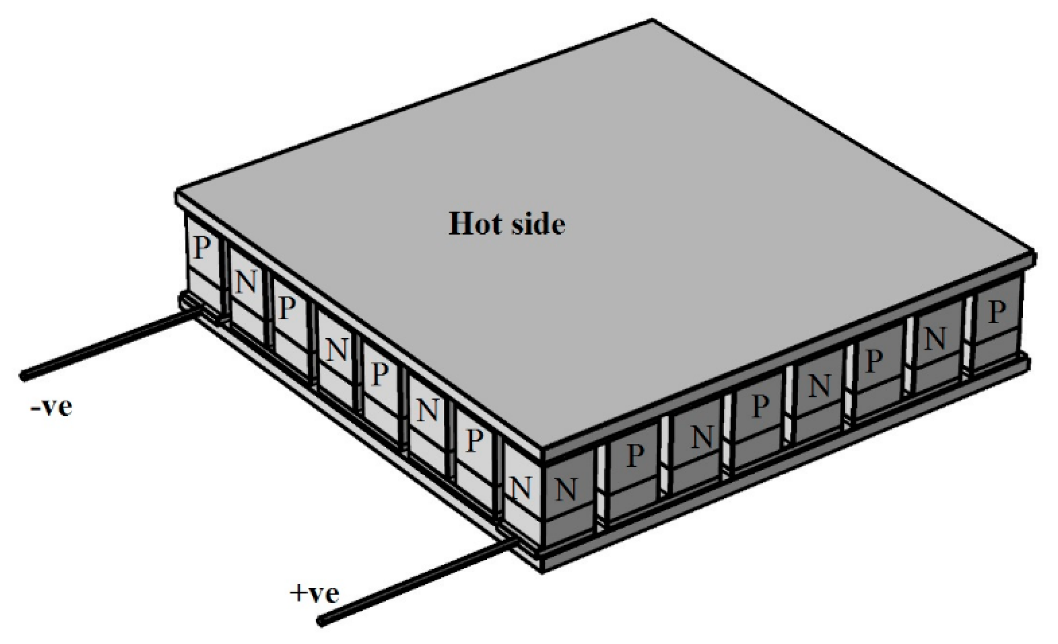
2.2. Thermoelectric Generator Module
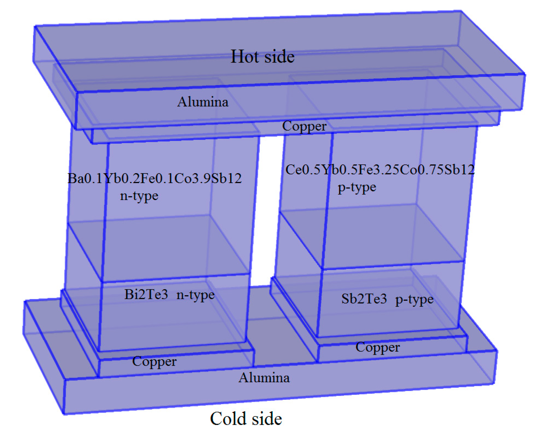
A thermoelectric generator module is an electrical series and a thermal parallel arrangement of n-type and p-type thermoelectric materials in the form of legs. The top and bottom of the legs are joined by conductors and are thermally insulated from the top and bottom by an insulator, i.e., alumina. Heat applied to the top side and the bottom side was kept at a low temperature; due to thermoelectric effects, voltage is produced across the n-type and p-type terminals, and by connecting the load across the terminals, output power and the conversion efficiency could be determined. Figure 1 shows a typical segmented thermoelectric generator module.
Recently, TEG modules are being designed and simulated in 3D using Comsol-Multiphysics (COMSOL Inc., Burlington, Stockholm, Sweden) or ANSYS engineering simulation and 3D design software. Usually, researchers begin the design and simulation of a unicouple TEG and later the design is scaled up to a module composed of a number of n-type and p-type legs. Zhonglian et al. carried out a comprehensive design and simulation of a segmented module [44]. However, a PbTeS TE material was used in the design. As lead (Pb) is a toxic element, it needs to be replaced, or another, less toxic, compound should be investigated. Here, skutterudite TE materials are investigated. By understanding the mathematical equations involved in the TEG, modelling and optimization can be achieved. Considering all of the possible thermal transfer losses, thermal and electrical contact resistances are negligible at a steady state, in which the heat is absorbed on the hot side and the heat rejected on the cold side.
Q h = n [ α I T H 1 2 I 2 R + K ( T H T c ) ]
Q C = n [ α I T c + 1 2 I 2 R + K ( T H T c ) ]
R = L ( 1 σ p A p + 1 σ n A n )
α = α p + α n
κ = 1 L ( κ p A p + κ n A n )
I = α ( T H T c ) R + R L
P o = Q h Q C = I 2 R L
Qh is the power absorbed at the hot junction, Q C is the power released at the cold junction, R , α , and κ are the internal resistance, Seebeck coefficient, and thermal conductivity of a unicouple, respectively. I is the electric current passing through the device, Po is the output power, and RL is the load resistance. A is the cross sectional area of the leg. Usually, n-type and p-type legs have equal lengths L, and n is the number of couples in a module. TH is the hot side temperature and Tc is the cold side temperature.

2.3. Segmentation

The modelling of the TEG enables the designer to optimize the design for better performance. From the Seebeck effect, the output voltage is proportional to the temperature gradient. It is desirable to operate a TEG over a wide range of temperature gradients. However, as TE materials are temperature dependent, it is challenging to find a single material that can operate efficiently over a wide range of temperatures. In order to achieve this, segmentation is called for. In a segmented TEG device, two or more TE materials can be arranged in sections across the length of the n-type and p-type legs of the TEG device. The figure of merit is the contribution of all the materials used. Segmentation, if done properly, results in a higher conversion efficiency. Factors to consider in segmentation are materials with a higher figure of merit and the compatibility factor s = 1 + Z T 1 α T . The compatibility factor of the materials considered for segmentation should not differ by a factor greater than two. Snyder [45] further stated that maximum efficiency occurs when the compatibility factor (s) is equal to the relative current density given by u = J k   T . Another condition for maximum conversion efficiency is R L R = 1 + Z T a v [44]. Figure 2 shows a simplified segmented unicouple of n-type Ba0.1Yb0.2Fe0.1Co3.9Sb12 [3], n-type Bi2Te3 [33], p-type Ce0.5Yb0.5Fe3.25Co0.75Sb12 [32],and p-type Sb2Te3 [34] materials. Skutterudites show high ZT at a mid-range temperature [3,32]. Bi2Te3 and Sb2Te3, however, generally undergo oxidation, volatility, and decomposition at a higher temperature. They show high ZT at a lower temperature around 100–150 °C [33,34]; as such, they are suitable for low temperature applications. Equations (8) and (9) give a typical figure of merit (k−1) for two materials’ segmentation and conversion efficiency.
Z = ( α p h + α p c + | α n h | + | α n c | ) 2 { [ ( K p h + K p c ) ( P p h + P p c ) ] 1 2 + [ ( K n h + K n c ) ( P n h + P n c ) ] 1 2 } 2
η = P o u t Q i n = T H T C T H   1 + Z T 1 1 + Z T + T c T H
where Z (k−1) is the figure of merit in segmentation involving two materials, pph, ppc, pnh, and pnc are the electrical resistivity of the hot and cold sides of the p-type and n-type TE materials, respectively. The same applied for the Seebeck coefficient and the thermal conductivity. T(k) is the average operating temperature, η is the TEG conversion efficiency.

2.4. Governing Equations for the Simulation

A finite element analysis method was employed in the modelling and analysis of the TEG in Comsol-Multiphysics. The governing equations are as follows [46]:
Heat transfer in solids: Energy balance
ρ C p u · T + · q = Q + Q t e d
Fourier’s law
q = k T
Thermal insulation
n · q = 0
Electric current: Current conservation
· J = Q j , v
Ohm’s law
J = σ E + J e
E =   V
Joule heating (irreversible process)
Q = J · E
Electric insulation
n · J = 0
Thermoelectric effects:
q = P J
P = S T
J e = σ S T
Electromagnetic heat source:
ρ C p u · T = · ( k   T ) + Q e
Q e = J · E
ρ = Density, Cp = Specific heat, Q = Heat source, J = Induced electric current, Qted = Thermoelectric effect, E = Electric field, V = Electric potential, S = Seebeck coefficient, P = Peltier coefficient, σ = Electrical conductivity, Qj = Current source, q = Heat flux in conduction, k = Thermal conductivity, T = Temperature, and Je = External current source.

3. Results

3.1. Discussion

Having successfully conducted the simulation for a segmented module (32 couples) with the cold side and interface temperatures of 300 k and 450 k, respectively. The hot side temperature for three different sets of simulations are 500 k, 600 k, and 800 k. For optimization, various simulations were carried out. The length of the legs should be long enough to gain optimum efficiency and minimum thermal stress, and should be short enough to produce high output power [47]. Thus, 6 mm was selected. From the cold side, the temperature at which Bi2Te3 and Sb2Te3 have the highest efficiency occurs at approximately one third of the length of the leg. Thus, the segmentation ratio is uniformed and found to be 2:1 skutterudites to chalcogenides, respectively. The cross-sectional area of the p-type leg was selected to be 4 mm × 4 mm. The resistivities of n-type and p-type legs for both skutterudites and chalcogenides materials are different. Having the same cross-sectional area will make the current pass through the leg with the highest resistance, which will result in a low output efficiency of the leg. For an optimal efficiency of the module, the n-type cross-sectional area should be less than p-type cross-sectional area via A n A p = σ p κ p σ n κ n [44]. The module has an overall dimension of 40   mm × 40   mm × 7   mm . As mentioned earlier, the compatibility factor is a key to increasing the conversion efficiency of the module. Figure 3 and Figure 4 show the p-type and n-type compatibility factors of the materials, respectively.
For the module simulation, the material properties were fully assigned and the heat transfer in the solids was defined (i.e., the temperature gradients of 500 K, 300 k, 200 k were specified). On the cold side, the ground was assigned to the n-type leg and the terminal was assigned to the p-type leg. Electrical circuit physics were added to include an electrical load resistor to the circuit. An external I Vs U 1, which operates as a voltage source within the circuit, was labelled properly to correspond to the resistor and ground node labels. The value of the internal resistance was calculated from Equation (3) at T∆ = 500 k is 0.2 Ω. The maximum power occurs when R L R = 1 . The condition for attaining maximum conversion efficiency differs to that of the maximum power. The thermoelectric effect, electromagnetic heat source, and boundary electromagnetic heat source were selected, while the boundary thermoelectric effect and temperature coupling were deselected. The type of physics controlled mesh was chosen, and the stationary study was selected for the computation of the results. Open circuit simulations for temperature gradients of 200 k, 300 k, and 500 k give an output voltage of 2.44 V, 3.82 V, and 6.2 V, and a matched load output power of 6.2 W, 15.2 W, and 45 W, respectively. To determine the maximum power and the maximum conversion efficiency, a parametric sweep of the load resistance was conducted. For each simulation, a 1D plot was selected from the result, then the y-axis data drop box displayed the current terminal and voltage terminal values for computing power, while the total net heat rate for T1 (hot side) was used to compute the efficiency.
At a temperature gradient of 500 k, the calculated conversion efficiency of the unsegmented skutterudite n-type Ba0.1Yb0.2Fe0.1Co3.9Sb12 and p-type Ce0.5Yb0.5Fe3.25Co0.75Sb12 based TEG module is 10%, while its maximum simulated efficiency is 9.2%. However, at the same temperature the calculated conversion efficiency of the segmented TEG device is 17.2%, while the maximum simulated conversion efficiency is 15.7%. Figure 5 shows the comparison of the simulated efficiencies of both the segmented module and the unsegmented module.
With these results, the segmentation is said to be successful. The segmented module has a 72% and 70.7% increase in the calculated and simulated conversion efficiency, respectively. Figure 6 shows the comparison of the calculated and the maximum simulated conversion efficiency at three different temperature gradients for the segmented TEG module. The maximum simulated values are lower than the calculated values. The higher values of calculated efficiencies are due to the fact that the thermal and electrical contact resistances associated with the TEG module are not included in the calculations.
Having confirmed (calculated and simulated) that the segmented TEG modules have a higher conversion efficiency than the unsegmented TEG modules, the other output parameters, such as output voltage, current passing through the device, and power, are determined. Figure 7 shows the plot of the output current versus the output voltage at three different temperature gradients. As expected, as the voltage increases the current decreases. Figure 8 shows the power plot against the load resistance. The power reaches maximum when the load resistance is equal to the internal resistance. After that point, the power starts decreasing until it reaches a point where it will no longer decrease. Figure 9 shows the plot of the output voltage against the load resistance. Here, as the voltage reaches its maximum (open circuit value), it remains constant irrespective of the load resistance.
Figure 10 shows the plot of efficiency against voltage. The efficiency increases until it reaches R L R = 1 + Z T a v , then it decreases to zero at the open circuit voltage value. Figure 11 shows the plot of efficiency against current. Figure 12 and Figure 13 show the plot of output power against current and output power against voltage, respectively.
By comparing Figure 11 with Figure 12, and Figure 10 with Figure 13, it can be said that the efficiency and the output power reach their maximum at different points. This confirms that the condition for maximum efficiency differs to that of the maximum power.

3.2. Contact Resistance

Whenever two materials are connected together, electrical and/or thermal contact resistances will be formed at the interface due to either surface roughness or excessive pressure being applied to the material interface during synthesis. Contact resistance is the major source of losses in TEG modules. Obtaining a low contact resistance is as important as enhancing the ZT values of TE materials. Electrical contact resistance occurs at the interface between the electrode-TE material and TE-TE material. The high value of the electrical contact resistance could introduce heat at a junction, which would subsequently reduce the output voltage. Thermal contact resistance, on the other hand, involves heat loss at the interface as the heat passes from one material to another. It is present at every interface. Contact resistance can be measured from a scanning probe technique or transmission line-based technique. To view the effect of thermal contact resistance and electrical contact resistance on the TEG model, parametric sweeps of 10−6–5 × 10⁻¹ m2 KW−1 and 10−10–5 × 10⁻⁵ Ωm2 were carried out, respectively. The reduction in the conversion efficiency was less than 20% in both cases. If segmentation increases the efficiency by 30%, then a thermal contact resistance of 20% or an electrical contact resistance of 30% can be accepted [48].

3.3. Radiation and Convection Losses

In a TEG module, due to heat transfer, there is always radiation and convection losses. This is because some of the energy is being absorbed or reflected by air molecules. A black body, in the concept of radiation, is a surface that absorbs all incident radiation and reflects none. A black body is a perfect radiator, it has an emissivity of ε = 1, which is the highest possible value. However, TEG modules do not act like a black body. The effect of radiation losses on the segmented TEG model has been investigated [44]. The ideal way to reduce the heat losses, which occur due to radiation and convection, is to either use an insulating material between the legs or evacuate the module completely and use short but wide legs closely spaced [49].

3.4. Diffusion Barrier

Lead-free solder alloys are often used to join an electrode and a TE material. It has been confirmed that an interfacial reaction exists between the solder and the TE material, leading to the creation of contact resistance and the possible degradation of TEG module performance [50]. In practical TEG modules, a diffusion barrier, usually in µm thickness, is inserted in between the solder and the TE material via either ultra-high-vacuum (UHV) radio frequency (RF) sputtering, spark plasma sintering, or electroplating procedures to inhibit the formation of intermetallic compounds at the same time as ensuring a good electrical bond. Its analysis is often conducted via SEM. The effect of diffusion layers, such Au, Pt, Ti, Ni, Co-P, and Ni-P on TEG modules has been investigated [50,51,52,53]. If an appropriate thickness is used, the diffusion layer can enhance the efficiency of a module. To avoid having a mismatch at the interface during expansion, the thermal coefficient of the diffusion layer should be similar to that of the TE material and the electrode. Bilayer metallization [54] and multilayer metallization [55] prove effective in lowering electrical contact resistance, providing thermal coefficient matching, and serve as a good diffusion barrier.

4. Conclusions

In this report, the conversion efficiency of the synthesized skutterudite n-type Ba0.1Yb0.2Fe0.1Co3.9Sb12 and p-type Ce0.5Yb0.5Fe3.25Co0.75Sb12 TEG module has been investigated. At a temperature gradient of 500 k, the unsegmented skutterudite-based TEG module has a maximum simulated conversion efficiency of 9.2% and a calculated efficiency of 10%, while the segmented skutterudite-based TEG module has a maximum simulated conversion efficiency of 15.7% and a calculated efficiency of 17.2%. This shows a substantial increase in the conversion efficiency, and it demonstrates that the segmentation is successful. The open circuit voltage is 6.2 V and the matched load output power is 45 W.

Author Contributions

S.B. synthesized the skutterudite TE materials, reviewed the manuscript and wrote the manuscript; A.Y. modelled the TEG module and wrote the manuscript. All authors have read and agreed to the published version of the manuscript.

Funding

This work received support from both Scientific and Technological Research Council of Turkey (TUBITAK) with project number 216M254 and Scientific Coordination Unit of Istanbul University with project numbers 21809 and 32641.

Conflicts of Interest

The authors declare no conflict of interest.

References

  1. Series, S. Introduction to Thermoelectricity; Goldsmid, H.J., Ed.; Springer: Berlin/Heidelberg, Germany, 2009; ISBN 9783642007156. [Google Scholar]
  2. Heremans, J.P.; Jovovic, V.; Toberer, E.S.; Saramat, A.; Kurosaki, K.; Charoenphakdee, A.; Yamanaka, S.; Snyder, G.J. Enhancement of thermoelectric efficiency in PbTe by distortion of the electronic density of states. Science 2008, 321, 554–557. [Google Scholar] [CrossRef] [PubMed] [Green Version]
  3. Ballikaya, S.; Uzar, N.; Yildirim, S.; Salvador, J.R. Electrical and thermal properties of Fe substituted double-filled BaxYbyFezCo4−zSb12 skutterudites. J. Solid State Chem. 2013, 197, 440–446. [Google Scholar] [CrossRef]
  4. Ballikaya, S.; Uher, C. Enhanced thermoelectric performance of optimized Ba, Yb filled and Fe substituted skutterudite compounds. J. Alloys Compd. 2014, 585, 168–172. [Google Scholar] [CrossRef]
  5. Prado-Gonjal, J.; Vaqueiro, P.; Nuttall, C.; Potter, R.; Powell, A.V. Enhancing the thermoelectric properties of single and double filled p-type skutterudites synthesized by an up-scaled ball-milling process. J. Alloys Compd. 2017, 695, 3598–3604. [Google Scholar] [CrossRef]
  6. Rogl, G.; Grytsiv, A.; Rogl, P.; Peranio, N.; Bauer, E.; Zehetbauer, M.; Eibl, O. N-Type skutterudites (R,Ba,Yb)yCo4Sb12 (R = Sr, La, Mm, DD, SrMm, SrDD) approaching ZT ≈ 2.0. Acta Mater. 2014, 63, 30–43. [Google Scholar] [CrossRef]
  7. Deng, S.K.; Li, D.C.; Shen, L.X.; Hao, R.T.; Takabatake, T. Sn-based type-VIII single-crystal clathrates with a large figure of merit. Chin. Phys. B 2012, 21, 017401. [Google Scholar] [CrossRef]
  8. Roudebush, J.H.; Toberer, E.S.; Hope, H.; Jeffrey Snyder, G.; Kauzlarich, S.M. Crystal structure, characterization and thermoelectric properties of the type-I clathrate Ba8−ySryAl14Si32 (0.6 ≤ y ≤ 1.3) prepared by aluminum flux. J. Solid State Chem. 2011, 184, 1176–1185. [Google Scholar] [CrossRef]
  9. Shi, X.; Yang, J.; Bai, S.; Yang, J.; Wang, H.; Chi, M.; Salvador, J.R.; Zhang, W.; Chen, L.; Wong-Ng, W. On the design of high-efficiency thermoelectric clathrates through a systematic cross-substitution of framework elements. Adv. Funct. Mater. 2010, 20, 755–763. [Google Scholar] [CrossRef]
  10. Poon, S.J. Recent advances in thermoelectric performance of half-heusler compounds. Metals 2018, 8, 989. [Google Scholar] [CrossRef] [Green Version]
  11. Yu, C.; Zhu, T.J.; Shi, R.Z.; Zhang, Y.; Zhao, X.B.; He, J. High-performance half-Heusler thermoelectric materials Hf1−x ZrxNiSn1−ySby prepared by levitation melting and spark plasma sintering. Acta Mater. 2009, 57, 2757–2764. [Google Scholar] [CrossRef]
  12. Maji, P.; Makongo, J.P.A.; Zhou, X.; Chi, H.; Uher, C.; Poudeu, P.F.P. Thermoelectric performance of nanostructured p-type Zr0.5Hf 0.5Co0.4Rh0.6Sb1−xSnx half-Heusler alloys. J. Solid State Chem. 2013, 202, 70–76. [Google Scholar] [CrossRef]
  13. Feng, Y.; Jiang, X.; Ghafari, E.; Kucukgok, B.; Zhang, C.; Ferguson, I.; Lu, N. Metal oxides for thermoelectric power generation and beyond. Adv. Compos. Hybrid Mater. 2018, 1, 114–126. [Google Scholar] [CrossRef]
  14. Li, S.; Funahashi, R.; Matsubara, I.; Yamada, H.; Ueno, K.; Sodeoka, S. Synthesis and thermoelectric properties of the new oxide ceramics Ca3−xSrxCo4O9 + δ (x = 0.0–1.0). Ceram. Int. 2001, 27, 321–324. [Google Scholar] [CrossRef]
  15. Wu, T.; Gao, P. Development of perovskite-type materials for thermoelectric application. Materials 2018, 11, 999. [Google Scholar] [CrossRef] [PubMed] [Green Version]
  16. Bocher, L.; Aguirre, M.H.; Robert, R.; Logvinovich, D.; Bakardjieva, S.; Hejtmanek, J.; Weidenkaff, A. High-temperature stability, structure and thermoelectric properties of CaMn1−xNbxO3 phases. Acta Mater. 2009, 57, 5667–5680. [Google Scholar] [CrossRef]
  17. Ballikaya, S.; Oner, Y.; Temel, T.; Ozkal, B.; Bailey, T.P.; Toprak, M.S.; Uher, C. Thermoelectric and thermal stability improvements in Nano-Cu2 Se included Ag2 Se. J. Solid State Chem. 2019, 273, 122–127. [Google Scholar] [CrossRef]
  18. Biswas, K.; He, J.; Blum, I.D.; Wu, C.I.; Hogan, T.P.; Seidman, D.N.; Dravid, V.P.; Kanatzidis, M.G. High-performance bulk thermoelectrics with all-scale hierarchical architectures. Nature 2012, 489, 414–418. [Google Scholar] [CrossRef]
  19. Beekman, M.; Morelli, D.; Nolas, G. Better thermoelectrics through glass-like crystals. Nat. Mater. 2015, 14, 1182–1185. [Google Scholar] [CrossRef]
  20. Liu, H.; Shi, X.; Xu, F.; Zhang, L.; Zhang, W.; Chen, L.; Li, Q.; Uher, C.; Day, T.; Snyder Jeffrey, G. Copper ion liquid-like thermoelectrics. Nat. Mater. 2012, 11, 422–425. [Google Scholar] [CrossRef]
  21. Rogl, G.; Rogl, P. Skutterudites, a most promising group of thermoelectric materials. Curr. Opin. Green Sustain. Chem. 2017, 4, 50–57. [Google Scholar] [CrossRef]
  22. Uher, C. Skutterudites: Prospective Novel Thermoelectrics; Elsevier: Amsterdam, The Netherlands, 2001. [Google Scholar]
  23. Ballikaya, S.; Sertkol, M.; Oner, Y.; Bailey, T.P.; Uher, C. Fracture structure and thermoelectric enhancement of Cu2 Se with substitution of nanostructured Ag2Se. Phys. Chem. Chem. Phys. 2019, 21, 13569–13577. [Google Scholar] [CrossRef] [PubMed]
  24. Yang, J.; Chen, Y.; Peng, J.; Song, X.; Zhu, W.; Su, J.; Chen, R. Synthesis of CoSb3 skutterudite by mechanical alloying. J. Alloys Compd. 2004, 375, 229–232. [Google Scholar] [CrossRef]
  25. Yang, L.; Chen, Z.G.; Hong, M.; Han, G.; Zou, J. Enhanced Thermoelectric Performance of Nanostructured Bi2Te3 through Significant Phonon Scattering. ACS Appl. Mater. Interfaces 2015, 7, 23694–23699. [Google Scholar] [CrossRef] [PubMed]
  26. Forster, J.D.; Lynch, J.J.; Coates, N.E.; Liu, J.; Jang, H.; Zaia, E.; Gordon, M.P.; Szybowski, M.; Sahu, A.; Cahill, D.G.; et al. Solution-Processed Cu2Se nanocrystal films with bulk-like thermoelectric performance. Sci. Rep. 2017, 7, 2765. [Google Scholar] [CrossRef] [PubMed] [Green Version]
  27. Ibáñez, M.; Luo, Z.; Genç, A.; Piveteau, L.; Ortega, S.; Cadavid, D.; Dobrozhan, O.; Liu, Y.; Nachtegaal, M.; Zebarjadi, M.; et al. High-performance thermoelectric nanocomposites from nanocrystal building blocks. Nat. Commun. 2016, 7, 10766. [Google Scholar] [CrossRef] [PubMed] [Green Version]
  28. Ortega, S.; Ibáñez, M.; Liu, Y.; Zhang, Y.; Kovalenko, M.V.; Cadavid, D.; Cabot, A. Bottom-up engineering of thermoelectric nanomaterials and devices from solution-processed nanoparticle building blocks. Chem. Soc. Rev. 2017, 46, 3510–3528. [Google Scholar] [CrossRef] [PubMed] [Green Version]
  29. Ballikaya, S.; Chi, H.; Salvador, J.R.; Uher, C. Thermoelectric properties of Ag-doped Cu2Se and Cu2Te. J. Mater. Chem. A 2013, 1, 12478–12484. [Google Scholar] [CrossRef]
  30. Dong, H.; Li, X.; Huang, X.; Zhou, Y.; Jiang, W.; Chen, L. Improved oxidation resistance of thermoelectric skutterudites coated with composite glass. Ceram. Int. 2013, 39, 4551–4557. [Google Scholar] [CrossRef]
  31. Tang, X.F.; Chen, L.D.; Goto, T.; Hirai, T.; Yuan, R.Z. Synthesis and thermoelectric properties of filled skutterudite compounds CeyFexCo4−xSb12 by solid state reaction. J. Mater. Sci. 2001, 36, 5435–5439. [Google Scholar] [CrossRef]
  32. Ballikaya, S.; Uzar, N.; Yildirim, S.; Chi, H.; Su, X.; Tan, G.; Tang, X.; Uher, C. Lower thermal conductivity and higher thermoelectric performance of Fe-substituted and Ce, Yb double-filled p-type skutterudites. J. Electron. Mater. 2013, 42, 1622–1627. [Google Scholar] [CrossRef]
  33. Saleemi, M.; Toprak, M.S.; Li, S.; Johnsson, M.; Muhammed, M. Synthesis, processing, and thermoelectric properties of bulk nanostructured bismuth telluride (Bi2Te3). J. Mater. Chem. 2012, 22, 725–730. [Google Scholar] [CrossRef]
  34. Zybała, R.; Mars, K.; Mikuła, A.; Bogusławski, J.; Soboń, G.; Sotor, J.; Schmidt, M.; Kaszyca, K.; Chmielewski, M.; Ciupiński, L.; et al. Synthesis and Characterization of Antimony Telluride for Thermoelectric and Optoelectronic Applications. Arch. Metall. Mater. 2017, 62, 1067–1070. [Google Scholar] [CrossRef] [Green Version]
  35. Tafti, M.Y.; Ballikaya, S.; Khachatourian, A.M.; Noroozi, M.; Saleemi, M.; Han, L.; Nong, N.V.; Bailey, T.; Uher, C.; Toprak, M.S. Promising bulk nanostructured Cu2Se thermoelectrics: Via high throughput and rapid chemical synthesis. RSC Adv. 2016, 6, 111457–111464. [Google Scholar] [CrossRef] [Green Version]
  36. Kim, H.; Ballikaya, S.; Chi, H.; Ahn, J.P.; Ahn, K.; Uher, C.; Kaviany, M. Ultralow thermal conductivity of β-Cu2Se by atomic fluidity and structure distortion. Acta Mater. 2015, 86, 247–253. [Google Scholar] [CrossRef] [Green Version]
  37. Bendt, G.; Weber, A.; Heimann, S.; Assenmacher, W.; Prymak, O.; Schulz, S. Wet-chemical synthesis of different bismuth telluride nanoparticles using metal organic precursors-single source vs. dual source approach. Dalton Trans. 2015, 44, 14272–14280. [Google Scholar] [CrossRef] [Green Version]
  38. Sirusi, A.A.; Ballikaya, S.; Uher, C.; Ross, J.H. Low-Temperature Structure and Dynamics in Cu2Se. J. Phys. Chem. C 2015, 119, 20293–20298. [Google Scholar] [CrossRef]
  39. Salvador, J.R.; Waldo, R.A.; Wong, C.A.; Tessema, M.; Brown, D.N.; Miller, D.J.; Wang, H.; Wereszczak, A.A.; Cai, W. Thermoelectric and mechanical properties of melt spun and spark plasma sintered n-type Yb- and Ba-filled skutterudites. Mater. Sci. Eng. B 2013, 178, 1087–1096. [Google Scholar] [CrossRef]
  40. Martynova, K.V.; Rogacheva, E.I. Thermoelectric properties of cold pressed samples of semiconductor (Bi1-xSbx)2Te3 solid solutions. Funct. Mater. 2018, 25, 54–60. [Google Scholar] [CrossRef]
  41. Cui, J.L.; Xue, H.F.; Xiu, W.J. Microstructures and thermoelectric properties of p-type pseudo-binary AgxBi0.5Sb1.5−xTe3 (x = 0.05–0.4) alloys prepared by cold pressing. Mater. Lett. 2006, 60, 3669–3672. [Google Scholar] [CrossRef]
  42. Nguyen, V.Q.; Nguyen, T.H.; Duong, V.T.; Lee, J.E.; Park, S.D.; Song, J.Y.; Park, H.M.; Duong, A.T.; Cho, S. Thermoelectric Properties of Hot-Pressed Bi-Doped n-Type Polycrystalline SnSe. Nanoscale Res. Lett. 2018, 13, 4–10. [Google Scholar] [CrossRef] [Green Version]
  43. Brož, P.; Zelenka, F.; Kohoutek, Z.; Vřešťál, J.; Vykoukal, V.; Buršík, J.; Zemanová, A.; Rogl, G.; Rogl, P. Study of thermal stability of CoSb3 skutterudite by Knudsen effusion mass spectrometry. Calphad Comput. Coupling Phase Diagrams Thermochem. 2019, 65, 1–7. [Google Scholar] [CrossRef]
  44. Ouyang, Z.; Li, D. Modelling of segmented high-performance thermoelectric generators with effects of thermal radiation, electrical and thermal contact resistances. Sci. Rep. 2016, 6, 24123. [Google Scholar] [CrossRef] [PubMed]
  45. Snyder, G.J. Application of the compatibility factor to the design of segmented and cascaded thermoelectric generators. Appl. Phys. Lett. 2004, 84, 2436–2438. [Google Scholar] [CrossRef] [Green Version]
  46. User’s Guide, COMSOL Multiphysics® v. 4.3; COMSOL AB: Stockholm, Sweden, 2012.
  47. Sarhadi, A.; Bjørk, R.; Pryds, N. Optimization of the Mechanical and Electrical Performance of a Thermoelectric Module. J. Electron. Mater. 2015, 44, 4465–4472. [Google Scholar] [CrossRef]
  48. Bjørk, R. The Universal Influence of Contact Resistance on the Efficiency of a Thermoelectric Generator. J. Electron. Mater. 2015, 44, 2869–2876. [Google Scholar] [CrossRef] [Green Version]
  49. Bjørk, R.; Christensen, D.V.; Eriksen, D.; Pryds, N. Analysis of the internal heat losses in a thermoelectric generator. Int. J. Therm. Sci. 2014, 85, 12–20. [Google Scholar] [CrossRef] [Green Version]
  50. Wu, H.J.; Wu, A.T.; Wei, P.C.; Chen, S.W. Interfacial reactions in thermoelectric modules. Mater. Res. Lett. 2018, 6, 244–248. [Google Scholar] [CrossRef]
  51. Song, B.; Lee, S.; Cho, S.; Song, M.J.; Choi, S.M.; Seo, W.S.; Yoon, Y.; Lee, W. The effects of diffusion barrier layers on the microstructural and electrical properties in CoSb3 thermoelectric modules. J. Alloys Compd. 2014, 617, 160–162. [Google Scholar] [CrossRef]
  52. Shi, L.; Huang, X.; Gu, M.; Chen, L. Interfacial structure and stability in Ni/SKD/Ti/Ni skutterudite thermoelements. Surf. Coat. Technol. 2016, 285, 312–317. [Google Scholar] [CrossRef]
  53. Zybala, R.; Wojciechowski, K.; Schmidt, M.; Mania, R. Junctions and diffusion barriers for high temperature thermoelectric modules. In Proceedings of the 11th International Conference and Exhibition of the European Ceramic Society, Krakow, Poland, 21–25 June 2009; Volume 1, pp. 341–344. [Google Scholar]
  54. Park, S.H.; Jin, Y.; Ahn, K.; Chung, I.; Yoo, C.Y. Ag/Ni Metallization Bilayer: A Functional Layer for Highly Efficient Polycrystalline SnSe Thermoelectric Modules. J. Electron. Mater. 2017, 46, 848–855. [Google Scholar] [CrossRef]
  55. Kim, Y.; Yoon, G.; Cho, B.J.; Park, S.H. Multi-layer metallization structure development for highly efficient polycrystalline SnSe thermoelectric devices. Appl. Sci. 2017, 7, 1116. [Google Scholar] [CrossRef] [Green Version]
Figure 1. Segmented thermoelectric generator module.
Applsci 10 00408 g001
Figure 2. Simplified segmented unicouple thermoelectric generator (TEG) for Voc measurement.
Applsci 10 00408 g002
Figure 3. P-type compatibility factor of the materials.
Applsci 10 00408 g003
Figure 4. N-type compatibility factor of the materials.
Applsci 10 00408 g004
Figure 5. Comparison of the simulated efficiencies for the segmented module and the unsegmented module.
Applsci 10 00408 g005
Figure 6. Comparison of the conversion efficiencies for the segmented TEG.
Applsci 10 00408 g006
Figure 7. Current versus output voltage.
Applsci 10 00408 g007
Figure 8. Output power versus load resistance.
Applsci 10 00408 g008
Figure 9. Output voltage versus load resistance.
Applsci 10 00408 g009
Figure 10. Conversion efficiency versus output voltage.
Applsci 10 00408 g010
Figure 11. Conversion efficiency versus current.
Applsci 10 00408 g011
Figure 12. Output power versus current.
Applsci 10 00408 g012
Figure 13. Output power versus voltage.
Applsci 10 00408 g013

