Article

Health-Related Electromagnetic Field Assessment in the Proximity of High Voltage Power Equipment

by
Mihaela Frigura-Iliasa
1,
Felicia Ioana Baloi
1,
Flaviu Mihai Frigura-Iliasa
1,2,*,
Attila Simo
1,2,
Sorin Musuroi
2,3 and
Petru Andea
1,2
1
Power Systems Department, Faculty of Electrical and Power Engineering, POLITEHNICA University of Timisoara, Piața Victoriei 2, 300006 Timișoara, Romania
2
Romanian Academy of Scientists, Timisoara Branch, 300006 Timișoara, Romania
3
Electrical Engineering Department, Faculty of Electrical and Power Engineering, POLITEHNICA University of Timisoara, Piața Victoriei 2, 300006 Timișoara, Romania
*
Author to whom correspondence should be addressed.
Appl. Sci. 2020, 10(1), 260; https://doi.org/10.3390/app10010260
Submission received: 19 November 2019 / Revised: 15 December 2019 / Accepted: 25 December 2019 / Published: 29 December 2019
(This article belongs to the Section Environmental Sciences)

Abstract

:
With respect to health issues, this paperpresents the results of an electromagnetic field (EMF) assessment in the proximity of a high voltage power station located in South Transylvania, Romania. The main parameters taken into account are, according to all standards and recommendations, the RMS (Root Mean Square) value of low frequency (0–300 Hz) electrical field strength E (in kV/m) and magnetic flux density B (in µT). Measurements were performed near all critical pieces of equipment (transformers, switches, busbars, overhead lines), according to the EMF European Directive. Some measurements were made as a function of distance from the HV (high-voltage) equipment, others as a time variation. The main objective was to verify that specific limits are met and, if necessary, to identify protective measures. Finally, safe exposure times for personnel operating at these sites were determined. In the future, detailed maps of EMF variations will be made available to the power companies.

1. Introduction

People, under the influence of news/articles published in mass media, are concerned with the effects of the electromagnetic field (EMF) on human health. The present paper gives an indirect answer to the concerns of the EMF and its distribution on the area of high-voltage (HV) electrical stations.
It is expected that in an area with a high density of high voltage equipment and circuits and in the immediate vicinity of electrical power stations, we will have high values for all EMF parameters.
Following the systematic studies carried out in different countries, it was concluded that the biological effects of EMF generated by high-voltage installations have a pathological significance.
Many specialists and experts are convinced that there is a close link between electromagnetic low-frequency pollution that is widespread and a considerable increase in the pathological condition known as “hypersensitivity to electromagnetic fields” or called Electromagnetic Hypersensitivity (EHS) [1,2].
Today, more and more people are experiencing EHS symptoms as a result of exposure to electromagnetic radiation and EMF, coming from mobile and wireless devices [3].
Normally, low-frequency EMF (1–300 Hz) are not considered dangerous, but if they are intense, they could become potentially dangerous [4].
Studies have shown that in a modern world, “electromagnetic smog” is responsible for the alarming increase in a number of new diseases such as chronic fatigue syndrome, fibromyalgia, pediatric oncology, asthma, autism, physiological and behavioral problems in children. These harmful factors are also considered to be the main causes of the occurrence and development of cardiovascular disease, cancer, and diabetes [4].
The EPA (US Environmental Protection Agency) in March 1990, qualified EMF as a Class B carcinogen (a possible carcinogen). In the same class, the EPA has positioned other well-known carcinogens such as formaldehyde, DDT, dioxins, and PCBs.
The Swedish government, after official investigations which lasted 25 years and involved 500,000 people, found indisputable evidence of the harmful effects caused by the fields formed by power lines. Currently, in Sweden, these electromagnetic fields are positioned in the second class of carcinogens, along with cigarettes [4].
To date, the pathological significance of the biological effects produced by exposure to the electromagnetic field generated by overhead electric lines (OHLs) is unknown. The problem of possible influences continues to concern the people, specialists in the field of sanitary protection, constructors of high and very high-voltage OHL, as well as the population in the vicinity of the power plants, lines or stations [5].
We avoid presenting the medical results of some publications because the opinions between specialists are extremely divided—from the documentation that presents a minimal to non-existent risk on a person’s health in the presence of these facilities, to others reporting the risk of developing different forms of cancer, in particular, an increased risk for children. However, certain values are known as the “limit” (defined in the next chapter), therefore, only by following some field measurements, can we say whether the measured values should raise a question mark or not.

2. Limits, Regulations, and Methods for the EMF (electromagnetic field) Assessment Process

Starting on the 1st of July 2016, all EU member states are required to implement Directive 2013/35/EU (also known as the EMF Directive) in their own national law, a directive that provides rules for the protection of persons against exposure to the electromagnetic field (EMF) [1]. As a result, all companies in the European Union are required to ensure that their employees are not exposed to electromagnetic radiation at levels higher than those defined by law. Some of these limits have just been defined in the new legislation. In Romania, the legislation includes the emergency ordinance GO (HG) 520 20/07/2016 regarding the minimum safety and health requirements regarding the exposure of workers to the risks generated by electromagnetic fields, as well as the order no. 1193/2006 regarding limiting the exposure of the general population to electromagnetic fields [6]. Thus, it is necessary to monitor and reduce the existing risk through preventive and corrective measures, where appropriate [7].
The main legislation on which the new European EMF Directive was based, is that issued by the ICNIRP (International Commission of Non-Ionizing Radiation Protection) [1].
The EMF Directive considers two biophysical categories of effects caused by ubiquitous electromagnetic fields:
  • thermal effects (range 100 kHz–300 GHz), such as the burning of skin tissues caused by energy absorption, which may occur upon exposure to high-frequency electromagnetic fields that may cause internal burns or blindness in extreme cases;
  • non-thermal effects (range 1 Hz–10 MHz), such as muscle stimulation, nerves or various senses, caused by exposure to low-frequency electromagnetic fields (in some cases such situations can cause optical illusions, for example).
Exposure Level Values (ELVs), which are based on the current intensity of the field inside the human body, are required to be respected for protection against any potential biophysical effect. However, they cannot be measured in practice, which is why Directive 2013/35/EU (also known as the EMF Directive) specifies the so-called action levels (AL—Action Levels) [8].
The safety of the human body placed in an electromagnetic field is thus ensured, according to law, if these levels are not exceeded.
The thermal and non-thermal effects are dependent both on the intensity of the field but also on its frequency. For this reason, the directive defines frequency-dependent action levels in the range of 100 kHz–300 GHz. For this reason, the measuring equipment must correctly evaluate the intensity of the electromagnetic fields in relation to the frequency and consider the individual effects, such as in the vicinity of a radio transmitter [9].
The non-thermal effects are also dependent on the frequency of the signal that produces the electromagnetic field. Higher levels can affect human health in the long term, and corrective and protective actions are required.
Low-frequency electromagnetic fields are usually present in the industrial environment and are usually pulsating fields. For this reason, the directive specifies the use of the WPM (Weighted Peak Method), which measures the peak values in the time domain as a reference method for non-sinusoidal wave fields. Measuring instruments already use this method, also called the shaped time domain (STD) method. This method is declared a reference method by the ICNIRP body, as well as by the EU Directive [1].
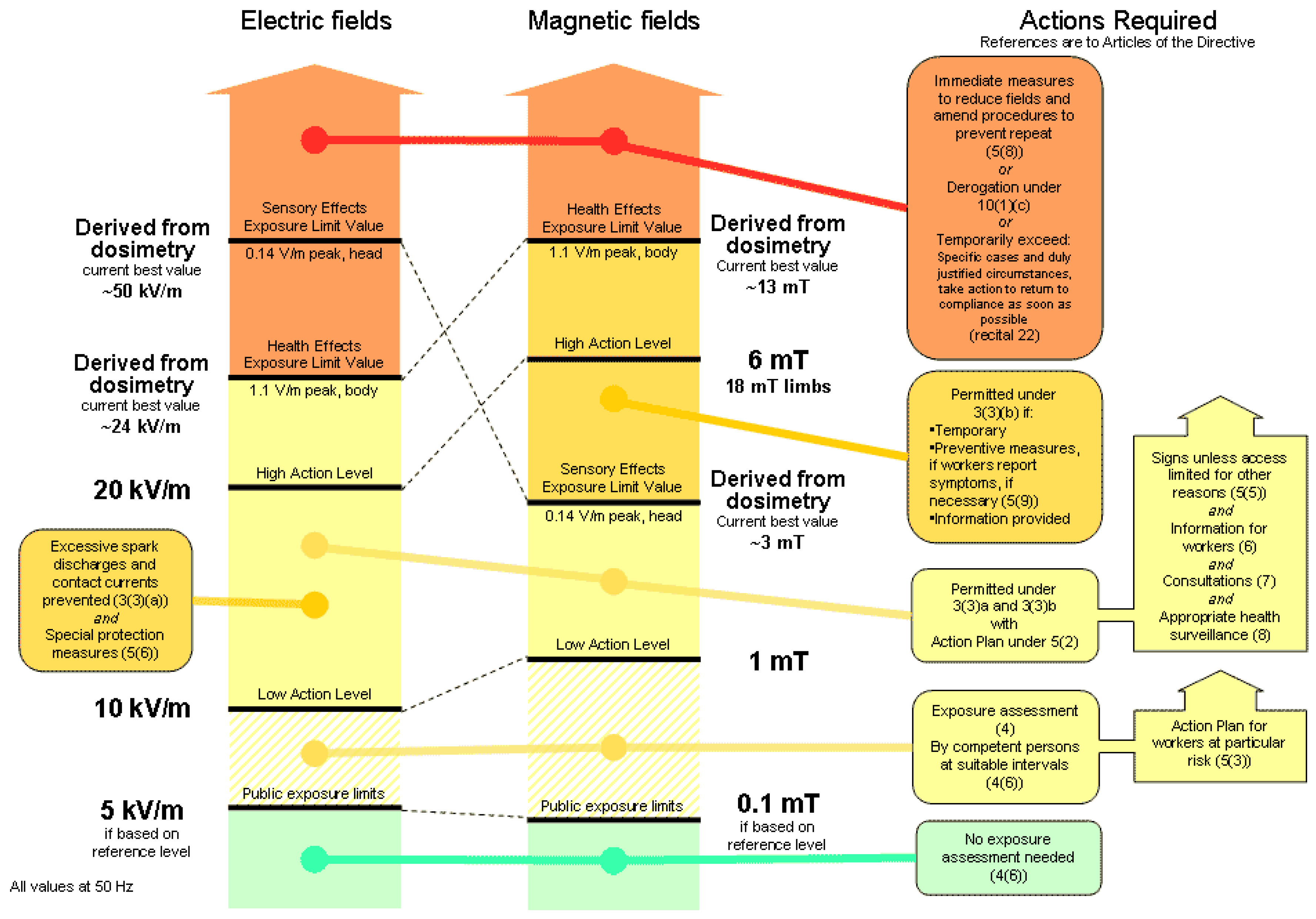
A new requirement of the EMF directive also specifies that the employer must develop a risk assessment method for each job. However, in most cases, such as in laboratories and offices where only low current devices are used, the declaration of conformity with the CE marking is sufficient. Of course, this principle is not applied in the case of HV equipment [10]. The EMF Directive stipulates “exposure limits values” (ELV, corresponding to the internal quantity, equivalent to ICNIRP’s “basic restriction”) and “action levels” (the external imposed field, equivalent to ICNIRP’s “reference level”). The graph has two levels: the “health” ELV and corresponding “high” action level, and the “sensory” ELV and corresponding “low” action level Figure 1 [2] presents these values at 50 Hz for electric and magnetic fields.
In Romania, the maximum values allowed by the legislation (according to The General Rules for Working Safety established in 1996) are:
  • For the electric field strength:
    • 10 kV/m on a full working shift;
    • 30 kV/m, for a short exposure time (less than 2 h);
    • The maximum exposure duration, calculated when the values of the field intensity are between 10 kV/m and 30 kV/m are calculated with the empiric relation t ≤ 80/E, where t represents the duration of the recalculated working day and E is the intensity of the electric field, in kV/m.
  • For the magnetic field induction:
    • 500 µT on a full working shift (some EU countries recommend 400 µT);
    • 5 mT for short time exposures (less than 2 h);
    • 25 mT for a short interval of exposure of the body extremities.
ICNIRP (the International Commission on Nonionizing Radiation Protection) Guide (1998), specifies as references for public exposure to the electromagnetic field, values of 5 kV/m for the electric field and 100 μT for the magnetic field having a frequency of 50 Hz [1]. These values were also included in the corresponding Recommendation of the Council of Europe (1999). On the other hand, as a general rule, the values of the magnetic field at the points accessible to the public within the OHL corridor are much lower than the 100 μT threshold, regardless of the nominal voltage of a line. Not the same can be said about the level of the electric field, whose intensity in the vicinity of overhead lines with nominal voltages above 300 kV exceeds the threshold of 5 kV/m. These studies were the fundament of the EU EMF Directive [11].
As we can notice from these regulations, the public exposure limits are more drastic than the operational ones, however, both of them are located below the low action level.
The 2013/35/EU Directive requires some different action plans at successive action levels and successive limit values for exposure. Figure 2 [2] outlines these aspects in a diagram. The main conclusions are:
  • an exposure assessment is mandatory as soon as public exposure limits are exceeded;
  • the action levels could be exceeded when various provisions are put in place;
  • the sensory limit values for exposure provided below can be expected if there is certain monitoring on any sensory effects that might arise;
  • the health exposure limit value must not be exceeded.
Below the high voltage lines, the electric field must be measured at a height of 1 m above the ground. If another measurement height is used (for technical reasons), it must be specified explicitly. The decision to perform measurements at a height other than 1 m can be indicated, determined by the need to reduce measurement uncertainties: it is known that the (potentially sustained) probes used to measure low-frequency electric fields are influenced by the insulating support (generally in the form of a tripod) on which they are placed [12]. Manufacturers of electric field measuring equipment, which together with the respective probe and tripod, recommend that it be “extended” to a certain height with the idea of sufficiently removing the probe from the support body and obtaining the specific measurement uncertainty. In the technical data sheet of the device.
Because the unevenness of the electric field under a high voltage line is negligible, a single measurement point is sufficient to evaluate the level of exposure of the human body in the considered place. The probe must be oriented so that the vertical component of the electric field is recorded because this component is used to characterize the induction effects in objects close to the surface of the earth [13].
The distance between the electric field probe and the operator must be, according to the standards, at least 1.5 m. It is to be emphasized that this minimum distance is necessary to avoid disturbance of the electric field by the operator. The distance between the probe and the operator must be at least 1.5 m for the measurement uncertainties to be less than 5% or 3 m for them to fall below 1%. It is obvious that in order to ensure these distances and to eliminate the operator’s influence on the measured values, it is necessary to use a fiber-optic connection between the electric field probe and the device on which the values are read (and if possible, stored).
In general, as mentioned above, high voltage stations represent electric field places of greatest interest. The level of the electric field is much lower in the case of distribution lines and medium voltage equipment, as in the vicinity of the electric stations. Usually, cable connections are not sources of an additional electric field.
The electric field varies with the height of suspension of the conductors and, therefore, its maximum value can be found by scanning the conductor in a longitudinal profile on a path parallel to it and at intervals (with steps) small enough to capture the maximum value.
At the point where the maximum value of the longitudinal profile was found (usually at the middle of the opening where the lengths of conductors are on maximum), the profile of the structure is explored in a direction perpendicular to its longitudinal axis. This last exploitation leads to the identification of the maximum field point [14].
Magnetic field sources near the measurement points, other than those of the systems to be evaluated, must be removed or disconnected in order to minimize the effect on the measured values. If it is impossible to perform such maneuvers, then the following data about them will be recorded; the type of source, their position in relation to the measurement points, etc.
The magnetic field must be measured at a height of 1 m from the ground level around the considered equipment at a horizontal distance of 0.3 m from the surface of the equipment, at intervals considered appropriate to find the maximum level point of the magnetic field [15].
Concerning non-permanent (movable) objects such as ferromagnetic materials, the measuring points will be arranged at distances at least three times higher than the height of those objects, in order to carry out measurements in non-disturbed (uniform) field areas. Locally, higher levels of the magnetic field can be found at smaller distances from the surface of the considered equipment. These values will not be considered as being representative of situations of normal public exposure.

3. Results of the Assessment Process

Measurement equipment was the Extech 480826 and Extech 450 m, certified for low-frequency EMF, according to all regulations.
The electric field measurements have the highest degree of relevance for the configuration of the connection scheme at the moment of the measurements.
Magnetic field measurements have a lower degree of relevance, given the variable loading conditions of the current path.
The calculation model of the magnetic field produced by a high voltage line is based on a quasi-static approximation. Only the longitudinal current is considered and the transversal current is totally neglected. Considering a system of three-phase lines, the total magnetic field is obtained from the superposition of the fields, taking into account the phase difference between the currents traveling lines. In general, the magnetic field generated by the three-phase lines is elliptical.
The calculation of the magnetic field is performed in a plane perpendicular to the conductor axes and it is based on the image method for conductors replacing the ground plan with a different virtual one, located at a certain depth below ground level.
The mandatory characteristics of the measuring equipment are:
  • Common characteristics relative to both measurements, the electric and magnetic field:
    • Mediation time for displaying the effective value: 1 s
    • Maximum instantaneous peak values evaluated over the last 250 ms
    • Data acquisition rate (refresh time) of the measuring system: 250 ms
    • Possibility of storing at least 1000 values for each measuring unit (electric or magnetic field; the electric field measuring unit can be programmed and can operate independently from the base unit, with its own memory).
  • Specific characteristics for the electric field measurement:
    • Triaxial probe, mountable on a tripod, connected by optical cable to the base unit. It can evaluate the value of the electric field strength components parallel to the coordinate axes, as well as the resulting value (isotropic);
    • Measuring range: 10 V/m..100 kV/m;
    • Measurement precision class at least 3%.
  • Specific characteristics for measuring the magnetic field:
    • Triaxial probe, incorporated in the basic unit. May indicate the value of the magnetic flux density components parallel to the coordinate axes, as well as the resulting value (isotropic);
    • Measuring range for the magnetic field (expressed in values of magnetic flux density in the air): 100 nT..50 mT;
    • Measurement precision class at least 5%.
The effective value, the maximum, and the isotropic value (the result of the values on the three axes) were measured with at least 3 s of waiting time before starting each procedure.
In addition to the measurement uncertainty, inherent to the device and specified by the manufacturer, some other factors highly influence the measurement process:
  • When measuring the electric field:
    • humidity (measurement errors increase with increasing relative humidity);
    • temperature (the low temperatures which determine condensation formation on the insulated parts of the equipment can influence the measurements);
    • the harmonics of the industrial frequency voltage (for the working procedure described above, these uncertainties are insignificant);
    • the inhomogeneity of the electric field.
  • When measuring the magnetic field:
    • non-uniformity of the magnetic field
    • the harmonics of the industrial frequency voltage (for the working procedure described above, these uncertainties are insignificant);
    • the non-orthogonality and the relative position of the measuring coils on the three coordinate axes (insignificant influences, small, compared to the uncertainty guaranteed by the manufacturer);
    • the inhomogeneity of the electric field.
All the measurement processes described in this paper are related to the Fintinele power station, located in South Transylvania, Romania, belonging to the National Power Grid Operator, Transelectrica S.A.
Figure 3 presents the layout of the Fintinele power station.
The electrical schema of the Fintinele Power Station is presented in Figure 4.
This power station has 3 voltage levels, 220 kV, 110 kV, and 20 kV. The two main power inputs, on 220 kV are located on the right side, and the 8 main outputs, on 20 kV, are located at the bottom.
This power station is not located in the proximity of public areas, and, by consequent, only occasional exposure must be taken into consideration.
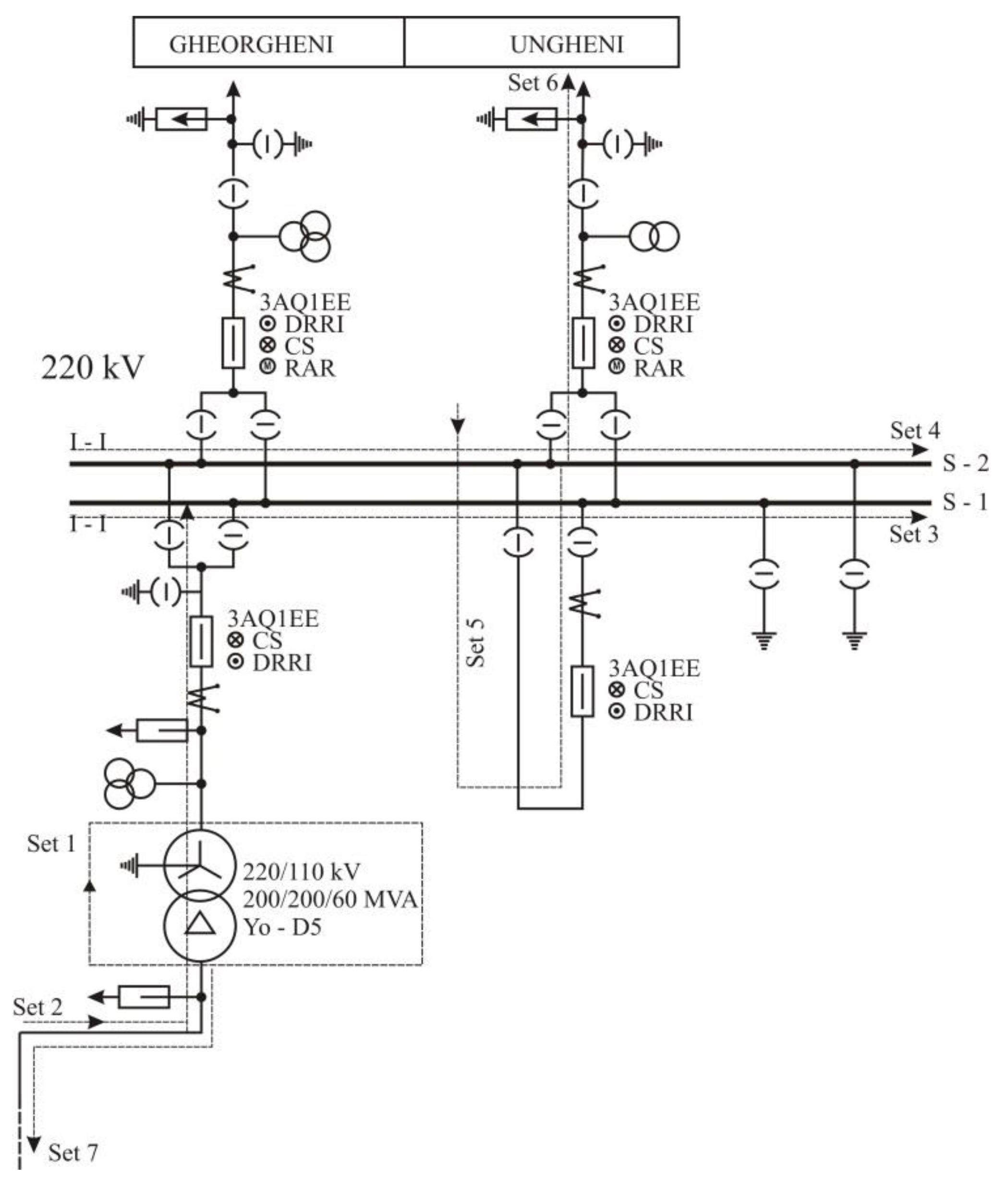
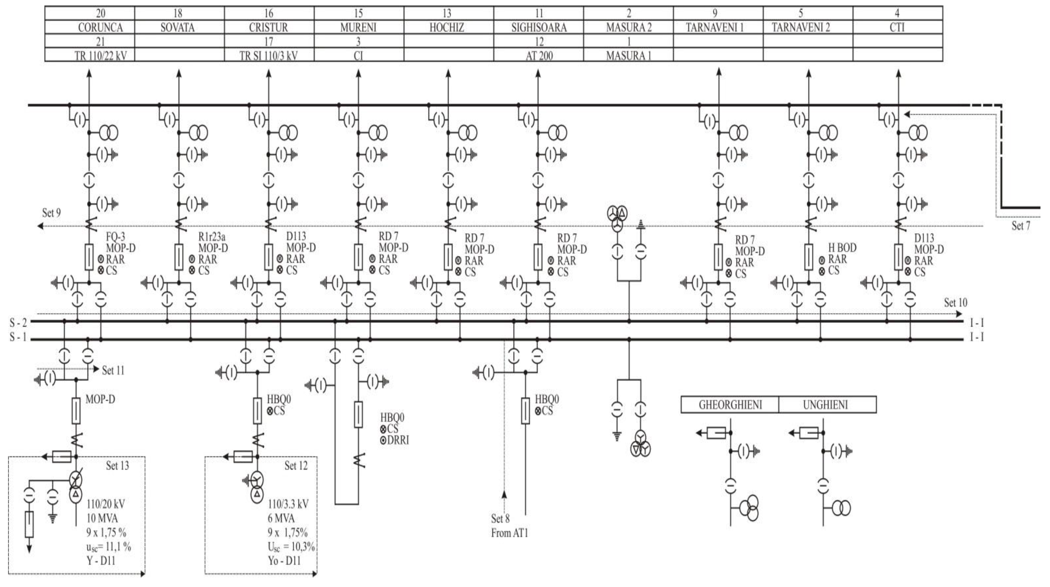
All measurements, both on the electric and the magnetic field, were performed on 15 specific set points, which are described in Figure 5, for sets 1–7, belonging to the autotransformer (AT) area and, in Figure 6, for sets 8–15, belonging to the distribution area.
These measurement set points were established according to standards, by taking into consideration any potential high value, due to the high field density, geometry, and layout or power concentration. The ideal solution is to multiply the measuring points, for obtaining a complete digital map of the whole power station, including all its substations.
The results will be presented in separate subsections, one for the electric field intensity and the other for the magnetic field induction, as described below. Some partial conclusions will be also presented in the same manner.

3.1. Electric Field Intensity Assessment Process

The maximum measured values obtained for the 15 critical set points are presented in Table 1. All of them were performed on the 24 July 2019, during the morning (8:00–10:00 a.m.), in excellent sunny weather conditions, with no rain or fog at temperatures from 24 up to 28 °C, and a relative humidity from 40 up to 46%, and an air pressure of 738 mmHg.
All measured values were located below the high action level, and, if limited exposure measures are applied, they are compliant with the safety working regulations. There are no human operators who must stay in the measured area for more than a few hours, except the command and control room where there are no risks at all (values around 2 kV/m).
The highest values are obtained for the transformers and autotransformers areas, but, as previously explained, there are no permanent human operators in those areas, at 3 m from the power transformers, in service mode.
Human staff in the commercial area reported frequent electric discharges at different levels, touching metallic or non-metallic objects, in conditions of high humidity, which can be explained by the electric charge on their bodies.
Electric discharges were observed between the joints of an umbrella with imperfect metal links, but also on hand-contact with the wet surface of fruit or vegetables, which reinforces the idea of the existence of a potentially harmful field in the analyzed area.
After the assessment processes, by considering more measurements than these presented, we observed that the first phase line has slightly higher values for the field intensity E, in most of the considered points. These values were obtained in excellent summer day conditions. During rain or higher humidity days, values could increase by 10 to 20% or, in worst cases, by 40%, but without concerns for human health (no maintenance operation is scheduled during heavy rains or extremely humid or foggy days).

3.2. Magnetic Field Induction Assessment Process

The maximum measured values obtained for the 15 critical set points are presented in Table 2. All of them were performed on the 24 July 2019, during the evening (8:00–10:00 p.m., when a maximum power consumption could occur), in excellent sunny weather conditions, with no rain or fog at temperatures from 26 up to 30 °C, and a relative humidity from 40% up to 50%, and an air pressure of 740 mmHg.
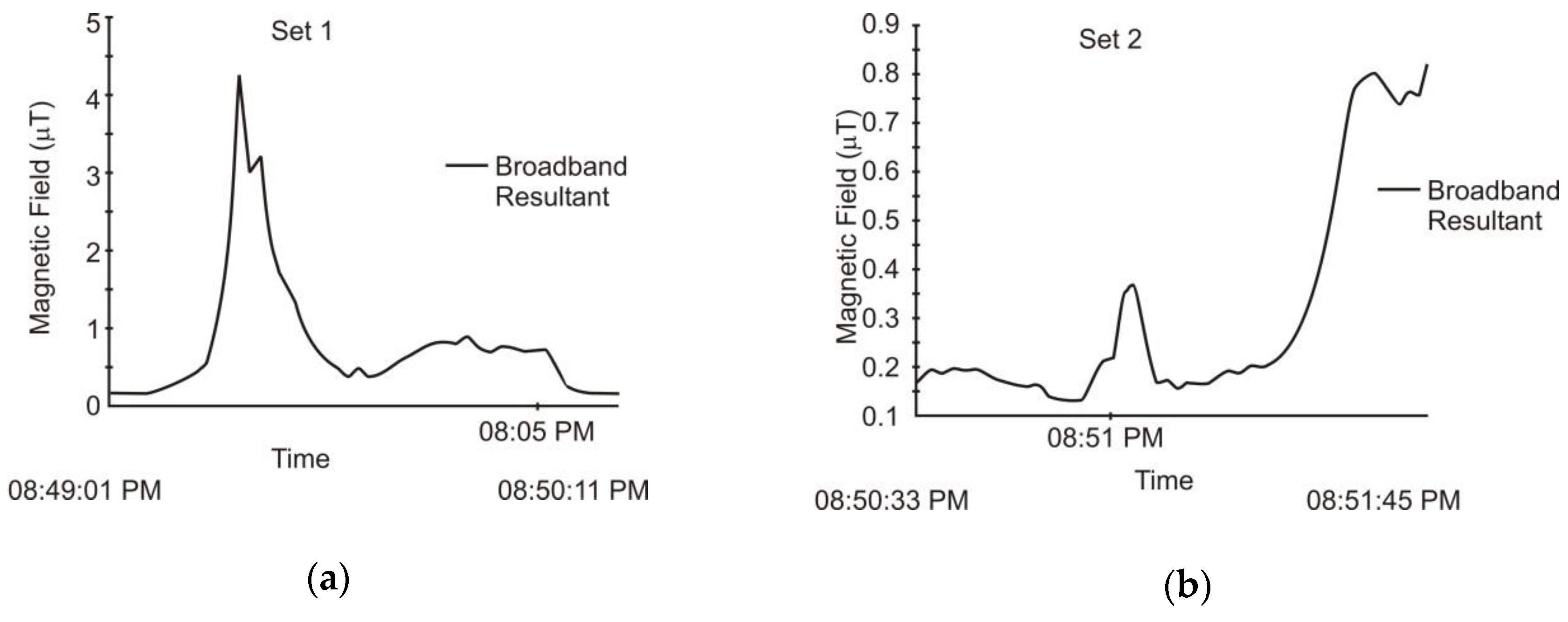
The magnetic field component depends on the load of the power system, and, by consequent, we must analyze the time variation of the magnetic field induction, especially during peak times of the day.
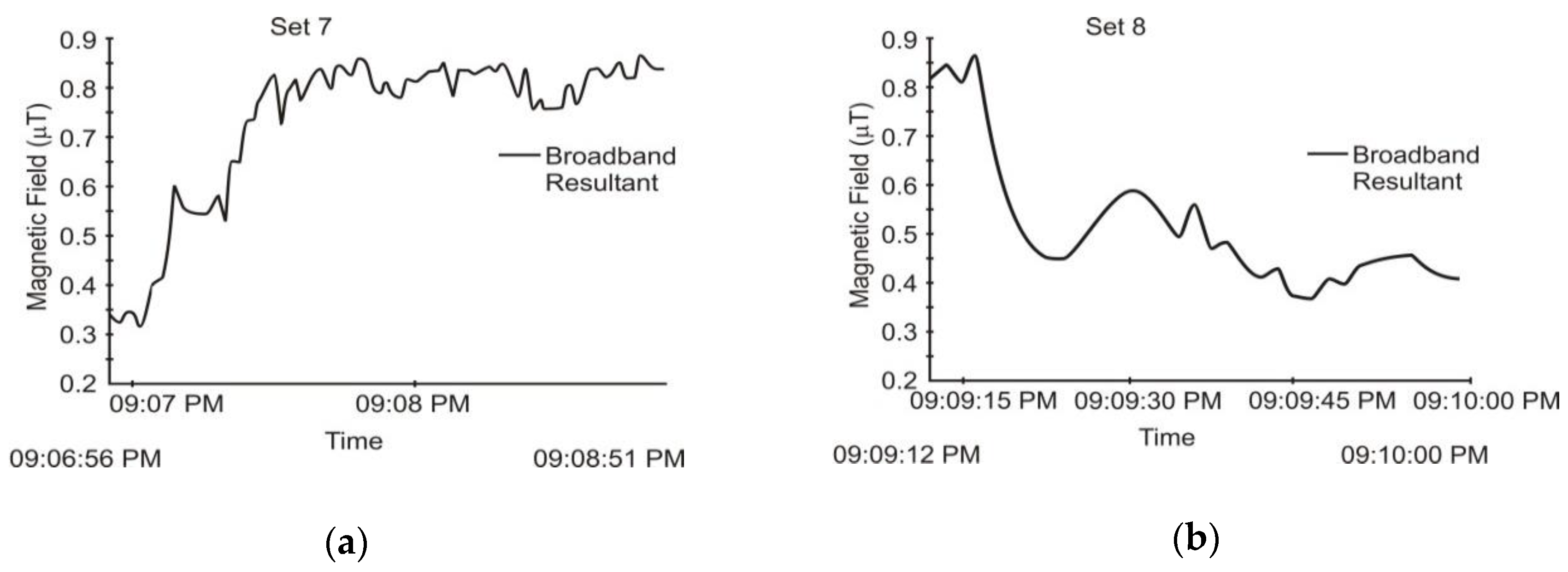
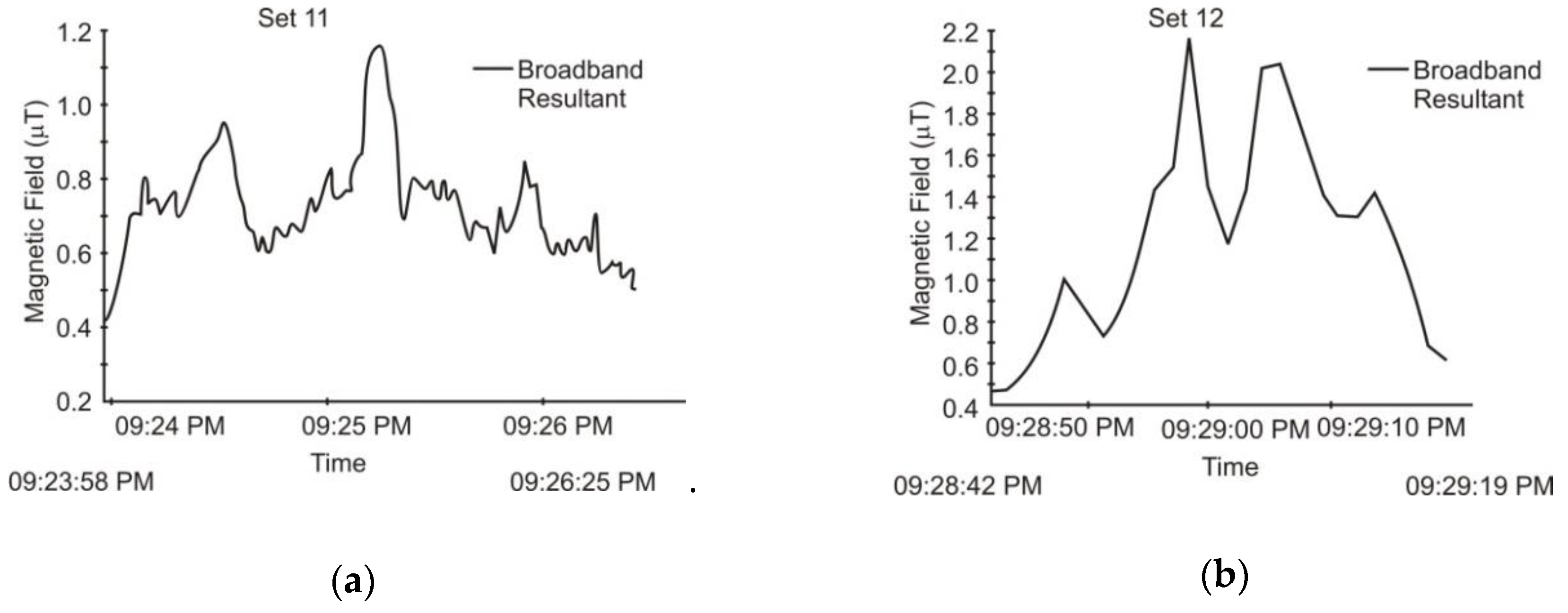
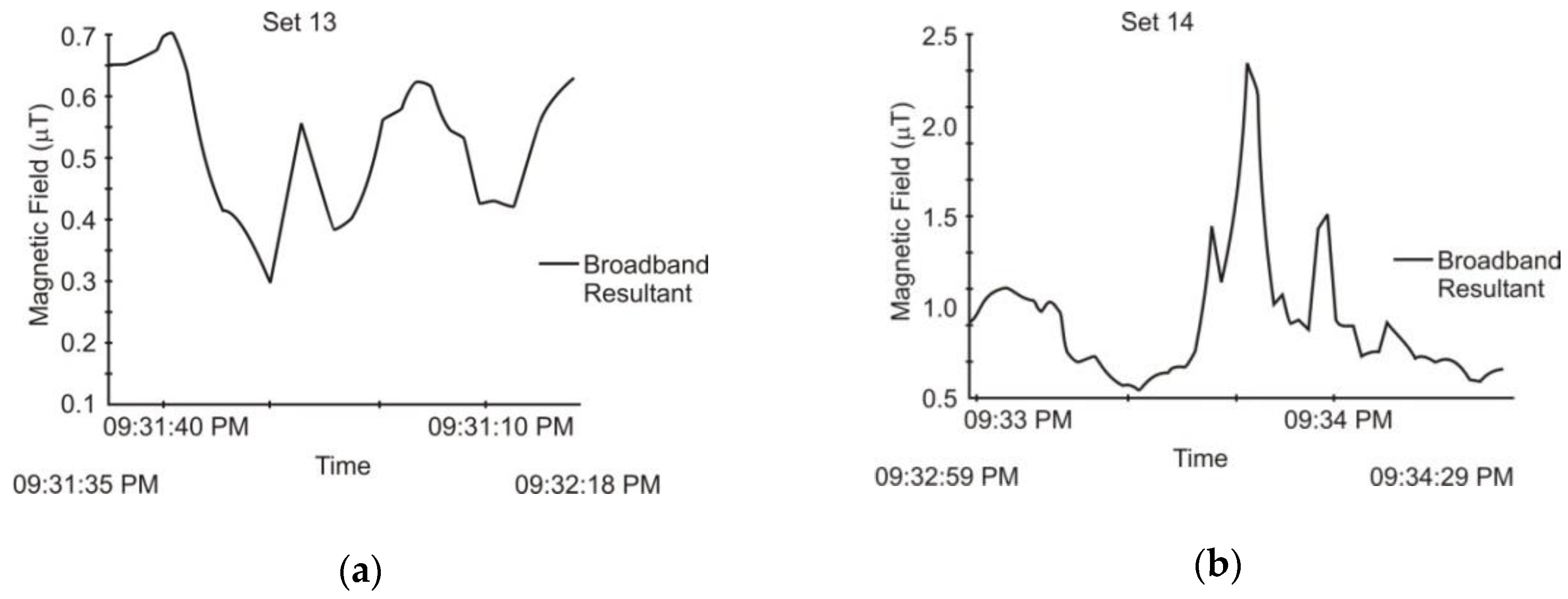
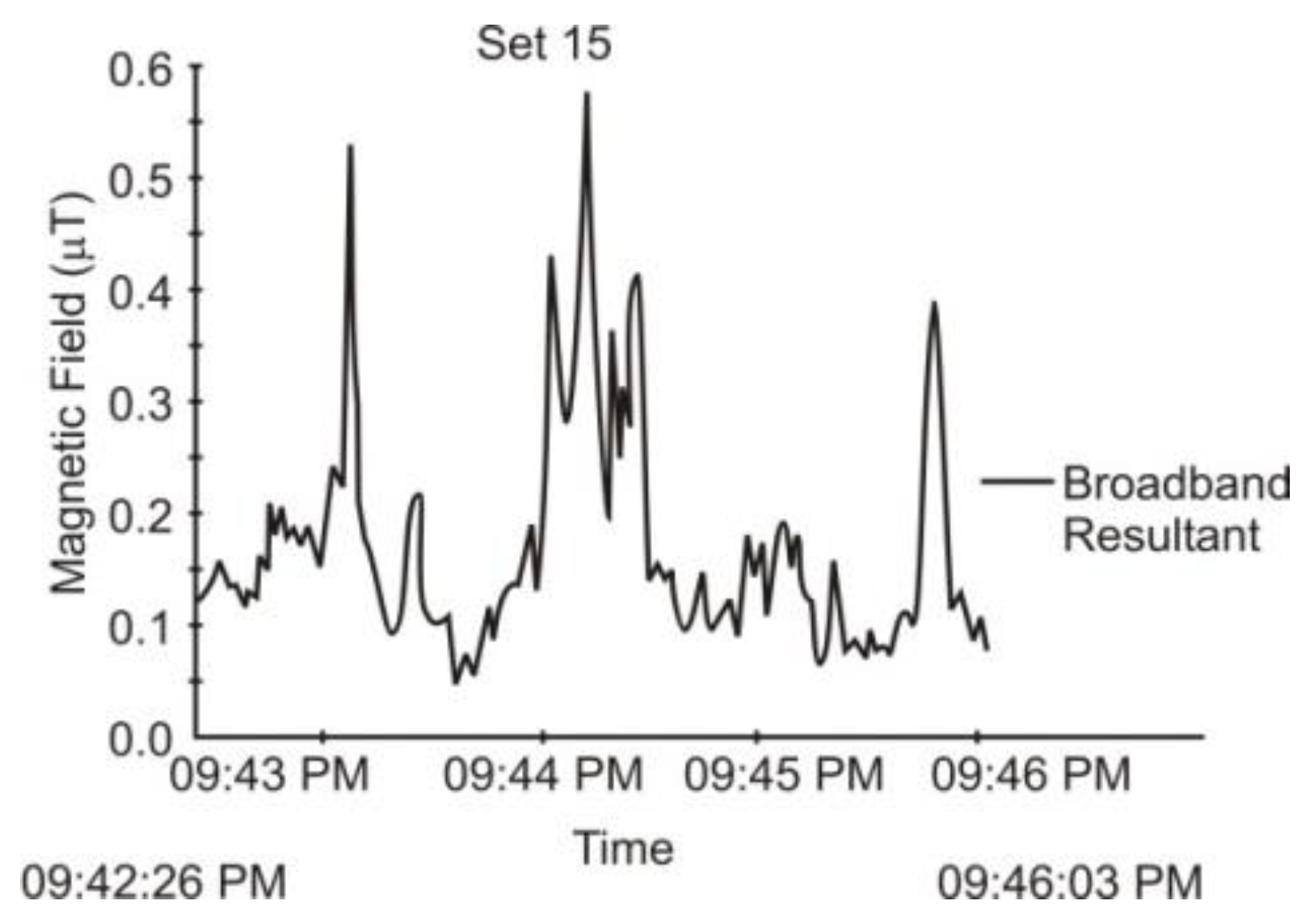
Next Figure 7, Figure 8, Figure 9, Figure 10, Figure 11, Figure 12, Figure 13 and Figure 14, will present the time evolution of the magnetic field induction during certain peak hours in the evening. All peak values are summarized in Table 2 around the maximum moment.

4. Discussion

After the assessment process of the electromagnetic field inside the considered stations, we observed that there are some values exceeding the limits of the electric field intensity, which can produce a few concerns, but there are no important issues about the magnetic field induction.
When taking into consideration the magnetic field, there are some possible recommendations:
  • Reduction of the dwell time in the electromagnetic field; exposure must be allowed only during the execution of works in installations;
  • Placement of warning plates in places with E ≥ 10 kV/m; the plates will be painted in yellow and their inscription will be red;
  • Installation of metal screens at workplaces (fixed or temporary screens), for example, when performing systematic works;
  • Train personnel to know precisely the places in the electrical installations where the electric field is E ≥ 10 kV/m and avoid an unjustified presence in those places;
  • Interdict personnel entering or remaining in areas with E ≥ 10 kV/m during meal breaks, rest or other non-working activities;
  • Use of electrically insulating gloves by personnel to protect against discharging currents that appear in contact with the grounded parts, when the carrier is placed in the electric field with E ≥ 10 kV/m.
Other technical measures that might be considered are [1]:
  • Establish and highlight jobs with a professional risk;
  • Modernize or refurbish installations;
  • Replace insulation or strengthen it;
  • Replace obsolete equipment;
  • Provide additional signaling on all power equipment;
  • Periodic control of the integrity of the earth sockets and connections;
  • Measure touch and step voltages by checking the direct links to earth;
  • Periodic verification of electrical equipment, supplying equipment, technical and lighting installations; perform repairs to installations according to the established programs;
  • Develop check tools, special devices, kits, and protective equipment, prior to the start of work, including insulation of primary cables and equipment;
  • Periodic determinations of the electric and magnetic field in the working environment, performed by authorized entities;
  • Update of all working instructions and occupational safety guidelines, with provisions in accordance with the new situations after the refurbishment of the installations;
  • Periodic training of staff with emphasis on workers’ awareness regarding the specific risks of the jobs and the protective measures adopted;
  • Respect the technological discipline and the discipline in the workplace;
  • Ensure all measures to obtain power densities below the maximum allowed limits;
  • Provide protective equipment to all employees according to the risks to their exposure risks;
  • Protect persons by using reflective surfaces of the electromagnetic field, for example, any type of metal foils;
  • Protect persons using screens in the workplace
Additionally, the attenuation of the magnetic field by shielding, if possible, using a structure in the form of sheets of different materials and of different sizes, which are located between the source of the field and the protected area. This solution is generally applied to cable lines.
The most commonly used magnetic field attenuation solutions are increasing the pillar height and conductive system management.
The technical solution of increasing the pillar height is advantageous when the conditions in the field require only a small reduction of the level of the magnetic field, just inside the lane of the line, because outside, the reduction of the magnetic field is completely insignificant.
A loop can be used to attenuate the magnetic field in the vicinity of a conducive OHL to a potential equal to or close to that of the earth. The impedance of this loop can be reduced in order to increase the current through the compensating conductor with the help of some capacitors connected in series. This technique used to manage the conductive systems is based on an additional compensation conductor system, which forms a loop. The parameters of this loop are selected in order to obtain the desired degree of magnetic field attenuation.
This method is based on generating an external current that is generated in the conductor system, monitored to create a magnetic field that superposes the source field. So, according to the law of magnetic induction, the magnetic flux created by the source system induces in the compensation conductor a current whose magnetic flux opposes and compensates the magnetic field of the source system.

5. Conclusions

The general conclusion taken from the literature is that we cannot accurately determine a defining, clear influence of exposure at low-frequency electromagnetic field radiation on the rate of certain diseases (carcinogenic, in particular).
Currently, the major interest is focused on the magnetic field generated by electrical installations, although the electric and magnetic field is simultaneously present in the occupied area of these installations.
On the considered case study, no major risks concerning the magnetic field induction values were observed. Only some excess values were found on measuring the electric field intensity, but all these values could be dealt with.

Author Contributions

Conceptualization, M.F.-I.; data curation, F.I.B.;fFormal analysis, M.F.-I.; investigation, F.I.B.; project administration, S.M.; resources, S.M. and P.A.; supervision, F.-M.F.-I.; validation, F.-M.F.-I. and P.A.; visualization, A.S.; writing—review and editing, M.F.-I. All authors have read and agreed to the published version of the manuscript.

Funding

This research received no external funding.

Acknowledgments

This work was supported by research grant GNaC2018 ARUT, no.1355/01.02.2019, financed by the Politehnica University of Timisoara.

Conflicts of Interest

The authors declare no conflict of interest.

References

  1. EU Council. Directive 2013/35/Eu of the European Parliament and of the Council of 26 June 2013. In Proceedings of the minimum health and safety requirements regarding the exposure of workers to the risks arising from physical agents (electromagnetic fields) (20th individual Directive within the meaning of Article 16(1) of Directive 89/391/EEC) and repealing Directive 2004/40/EC. Off. J. of the Eur. Union 2013, 179, 1–21. [Google Scholar]
  2. Electric and Magnetic Fields and Health. Available online: http://www.ems.info (accessed on 29 December 2019).
  3. Amman, M.; Dalleves, P.; Papailiou, K.O.; Leva, M.; Villa, S. A New 400kV Line with Compact Towers and Composite Insulated Cross Arms; CIGRE Report: Paris, France, 1998. [Google Scholar]
  4. Annual Report of World Health Organization (WHO) about the Extremely Low Frequency Electromagnetic Fields; World Health Organization (WHO): Geneve, Swiss, 2007.
  5. BCalabrò, E. Introduction to the Special Issue “Electromagnetic Waves Pollution”. Sustainability 2018, 10, 3326. [Google Scholar] [CrossRef] [Green Version]
  6. Gajšek, P.; Ravazzani, P.; Grellier, J.; Samaras, T.; Bakos, J.; Thuróczy, G. Review of Studies Concerning Electromagnetic Field (EMF) Exposure Assessment in Europe: Low Frequency Fields (50 Hz–100 kHz). Int. J. Environ. Res. Public Health 2016, 13, 875. [Google Scholar] [CrossRef] [PubMed] [Green Version]
  7. Boehmert, C.; Wiedemann, P.; Croft, R. Improving Precautionary Communication in the EMF Field? Effects of Making Messages Consistent and Explaining the Effectiveness of Precautions. Int. J. Environ. Res. Public Health 2016, 13, 992. [Google Scholar] [CrossRef] [PubMed] [Green Version]
  8. Zeleke, B.M.; Brzozek, C.; Bhatt, C.R.; Abramson, M.J.; Croft, R.J.; Freudenstein, F.; Wiedemann, P.; Benke, G. Personal Exposure to Radio Frequency Electromagnetic Fields among Australian Adults. Int. J. Environ. Res. Public Health 2018, 15, 2234. [Google Scholar] [CrossRef] [PubMed] [Green Version]
  9. Heredia-Rojas, J.A.; Rodríguez-De la Fuente, A.O.; Gomez-Flores, R.; Heredia-Rodríguez, O.; Rodríguez-Flores, L.E.; Beltcheva, M.; Castañeda-Garza, M.E. In Vivo Cytotoxicity Induced by 60 Hz Electromagnetic Fields under a High-Voltage Substation Environment. Sustainability 2018, 10, 2789. [Google Scholar] [CrossRef] [Green Version]
  10. Loughran, S.P.; Al Hossain, M.S.; Bentvelzen, A.; Elwood, M.; Finnie, J.; Horvat, J.; Iskra, S.; Ivanova, E.P.; Manavis, J.; Mudiyanselage, C.K.; et al. Bioelectromagnetics Research within an Australian Context: The Australian Centre for Electromagnetic Bioeffects Research (ACEBR). Int. J. Environ. Res. Public Health 2016, 13, 967. [Google Scholar] [CrossRef] [PubMed] [Green Version]
  11. Bürgi, A.; Sagar, S.; Struchen, B.; Joss, S.; Röösli, M. Exposure Modelling of Extremely Low-Frequency Magnetic Fields from Overhead Power Lines and Its Validation by Measurements. Int. J. Environ. Res. Public Health 2017, 14, 949. [Google Scholar] [CrossRef] [PubMed] [Green Version]
  12. Zhang, X.; Ni, X.; Wei, B.; Wang, S.; Yang, Q. Characteristic Analysis of Electromagnetic Force in a High-Power Wireless Power Transfer System. Energies 2018, 11, 3088. [Google Scholar] [CrossRef] [Green Version]
  13. Fiocchi, S.; Liorni, I.; Parazzini, M.; Ravazzani, P. Assessment of Foetal Exposure to the Homogeneous Magnetic Field Harmonic Spectrum Generated by Electricity Transmission and Distribution Networks. Int. J. Environ. Res. Public Health 2015, 12, 3667–3690. [Google Scholar] [CrossRef] [PubMed] [Green Version]
  14. Loughran, S.P.; Verrender, A.; Dalecki, A.; Burdon, C.A.; Tagami, K.; Park, J.; Taylor, N.A.S.; Croft, R.J. Radiofrequency Electromagnetic Field Exposure and the Resting EEG: Exploring the Thermal Mechanism Hypothesis. Int. J. Environ. Res. Public Health 2019, 16, 1505. [Google Scholar] [CrossRef] [PubMed] [Green Version]
  15. Jesudason, C.G. Broad Considerations Concerning Electrochemical Electrodes in Primarily Fluid Environments. Int. J. Mol. Sci. 2009, 10, 2203–2251. [Google Scholar] [CrossRef] [PubMed] [Green Version]
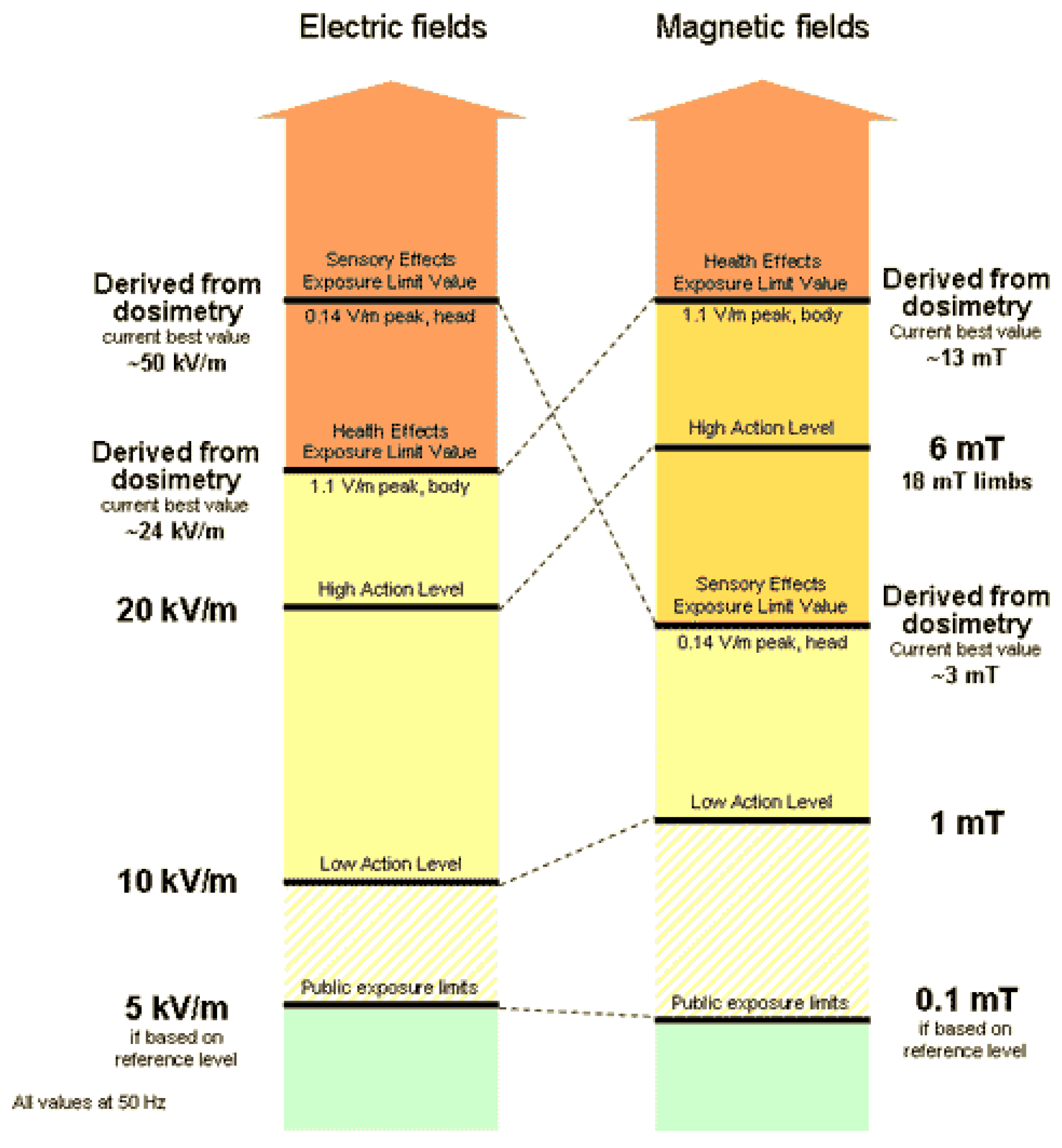
Figure 1. Electric and Magnetic field limits at 50 Hz.
Applsci 10 00260 g001
Figure 2. Specific actions for different action levels in the case of low-frequency EMF (electromagnetic field).
Applsci 10 00260 g002
Figure 3. Fintinele Power Station.
Applsci 10 00260 g003
Figure 4. The electrical schema of Fintinele Power Station.
Applsci 10 00260 g004
Figure 5. The Measuring Set Points for the Autotransformer area.
Applsci 10 00260 g005
Figure 6. The Measuring Set Points for the Distribution Substation.
Applsci 10 00260 g006
Figure 7. Time variation of the magnetic field induction on an evening peak of power consumption: (a) Measurements on Set Point 1; (b) Measurements on Set Point 2.
Applsci 10 00260 g007
Figure 8. Time variation of the magnetic field induction on an evening peak of power consumption: (a) Measurements on Set Point 3; (b) Measurements on Set Point 4.
Applsci 10 00260 g008
Figure 9. Time variation of the magnetic field induction on an evening peak of power consumption: (a) Measurements on Set Point 5; (b) Measurements on Set Point 6.
Applsci 10 00260 g009
Figure 10. Time variation of the magnetic field induction on an evening peak of power consumption: (a) Measurements on Set Point 7; (b) Measurements on Set Point 8.
Applsci 10 00260 g010
Figure 11. Time variation of the magnetic field induction on an evening peak of power consumption: (a) Measurements on Set Point 9; (b) Measurements on Set Point 10.
Applsci 10 00260 g011
Figure 12. Time variation of the magnetic field induction on an evening peak of power consumption: (a) Measurements on Set Point 11; (b) Measurements on Set Point 12.
Applsci 10 00260 g012
Figure 13. Time variation of the magnetic field induction on an evening peak of power consumption: (a) Measurements on Set Point 13; (b) Measurements on Set Point 14.
Applsci 10 00260 g013
Figure 14. Time variation of the magnetic field induction on an evening peak of power consumption: Measurements on Set Point 15.
Applsci 10 00260 g014
Table 1. Maximum measured values for the electric field intensity.
Set PointDescription of the Measurement SetpointMaximum Electric Field Intensity E [kV/m]
Set 1AT1—Autotransformer block 220/110 kV13.6
Set 2AT1—Autotransformer cell 220 kV12.4
Set 3S1 220 kV bus-bar11.3
Set 4S2 220 kV bus-bar8.6
Set 5Transversal connection bus-bar on 220 kV3.8
Set 6Substation Cell Ungheni4.4
Set 7Substation Cell Gheorgheni3.6
Set 8Connection point with distribution substations3.4
Set 9AT1—Autotransformer cell 110 kV6.7
Set 10Circuit breakers zone 110 kV9.9
Set 11Pedestrian access path near S1 110 kV bus-bar3.2
Set 12110/3 kV transformer3.5
Set 13110/20 kV Transformer16.2
Set 1420 kV substation7.8
Set 15Command and control room2.2
Table 2. Maximum measured values for the magnetic field induction.
Set PointDescription of the Measurement SetpointMaximum Magnetic Field Induction
B [μT]
Set 1AT1—Autotransformer block 220/110 kV4.48
Set 2AT1—Autotransformer cell 220 kV0.83
Set 3S1 220 kV bus-bar3.49
Set 4S2 220 kV bus-bar6.54
Set 5Transversal connection bus-bar on 220 kV4.57
Set 6Substation Cell Ungheni7.6
Set 7Substation Cell Gheorgheni0.85
Set 8Connection point with distribution substations0.91
Set 9AT1—Autotransformer cell 110 kV1.71
Set 10Circuit breakers zone 110 kV1.12
Set 11Pedestrian access path near S1 110 kV bus-bar1.14
Set 12110/3 kV transformer2.12
Set 13110/20 kV Transformer0.71
Set 1420 kV substation2.46
Set 15Command and control room0.58