Article

Effect of Hot Water Setting Temperature on Performance of Solar Absorption-Subcooled Compression Hybrid Cooling Systems

1
School of Electric Power, South China University of Technology, Guangzhou 510640, China
2
Guangdong Province Key Laboratory of High Efficient and Clean Energy Utilization, South China University of Technology, Guangzhou 510640, China
3
Guangdong Province Engineering Research Center of High Efficient and Low Pollution Energy Conversion, Guangzhou 510640, China
*
Author to whom correspondence should be addressed.
Appl. Sci. 2020, 10(1), 258; https://doi.org/10.3390/app10010258
Submission received: 6 October 2019 / Revised: 25 November 2019 / Accepted: 25 December 2019 / Published: 29 December 2019
(This article belongs to the Special Issue Building Physics and Building Energy Systems)

Abstract

:
The solar absorption-subcooled compression hybrid cooling system (SASCHCS) displays outstanding advantages in high-rise buildings. Since the performance coupling of collectors and absorption subsystems is stronger due to the absence of backup heat and the effect of generator setting temperature has not been realized adequately, it is highly important to study the relationship of SASCHCS operation and the set point temperature of hot water to prevent performance deterioration by inappropriate settings. Therefore, the paper mainly deals with the effect of collector and generator setting temperature. The investigation was based on the entire cooling period of a typical high-rise office building in subtropical Guangzhou. The off-design model of hybrid systems was built at first. Subsequently, the impact mechanism of setting temperature in two hot water cycles on facility operation was analyzed. It was found that the excessive rise of collector setting temperature deteriorated the energy saving, while the appropriate improvement of generator set point temperature was beneficial for the solar cooling. Besides, global optimization by the genetic algorithm displayed that 71.6 °C for the collector setting temperature with 64.5 °C for the generator was optimal for annual operation. The paper is helpful in enhancing the operation performance of SASCHCS.

1. Introduction

The energy consumption of air conditioning accounts for 50% of building consumption and 15% of total electricity consumption, respectively [1,2]. Because solar energy is abundant and coincident with cooling loads, solar refrigeration systems display significant energy saving potential in air conditioning. Solar LiBr/H2O single effect absorption chillers are widespread due to simplicity, high efficiency, as well as low cost among all solar thermal cooling [3]. However, it faces an economical obstacle in high-rise buildings owing to the excessive consumption of auxiliary thermal energy [4]. Considering that the number of high-rise buildings and the corresponding consumption grow notably because of increasing urban population and land price [5], more attention should be paid to the energy saving of such buildings. Li [6] proposed the solar absorption-subcooled compression hybrid cooling system (SASCHCS) as the economically feasible solution of high-rise buildings. It was found that the financial improvement mainly lies in the high performance of the absorption subsystem and the remarkable reduction of operational cost [7]. Besides, the prototype experiment showed that compressor works are saved by 22.2% on sunny days [8]. Therefore, the economic performance of SASCHCS rises dramatically, i.e., the payback period of hybrid systems is close to that of solar photovoltaic cooling (the most economical solution of solar refrigeration in recent years) in high-rise buildings [9]. It was shown that the area of compression subsystem evaporators and condensers as well as the size of absorption subsystems are critical for the exergoeconomic design of SASCHCS [10]. In particular, the optimal design of the above-mentioned parameters is dependent on the working condition distribution, i.e., absorption subsystems with moderate size are appropriate for the performance improvement if the hot water temperature mainly lies in the range 75–90 °C [11]. In addition to the system design, the performance also relies on the reasonable control of solar heat. The variable flow rate strategy in which flow rates of hot water are adjusted automatically according to the setting temperature is one of the widely-used control approaches in solar thermal systems. For the actual operation of SASCHCS, the performance suffers from notable decrease as a result of inappropriate setting temperature, i.e., the heat loss of collectors goes up and the useful heat drops dramatically by the increased temperature in spite of the rise in the coefficient of performance (COP) in absorption subsystems if the temperature of the generator hot water is set too high. Consequently, the relationship of SASCHCS operation and hot water set point temperature must be exact.
It was shown that the fixed outlet temperature is more appropriate than the constant inlet one for collector operation if flow rates of hot water can be controlled to make above-mentioned temperatures fixed during the entire period [12]. For solar domestic hot water facilities, it was found that the solar fraction associated with the constant temperature rise of collectors was only 2% more than that regarding fixed outlet temperatures [13]. Similar trends were also obtained by Rehman [14]. Araujo [15] compared the strategy with respect to constant and variable collector flow rates and found that the performance of solar domestic hot water systems with variable flow rate strategy was better than that with the constant one, especially for collectors with greater heat loss, i.e., the annual mean solar fraction with the variable flow rate strategy was 50% higher than that with the constant one for unglazed collectors. Furthermore, it was derived that the drop of set point temperature in collector outlet just enhanced 0.6% of heating power in solar district heating systems [16]. For solar power plants, it was concluded that the variable hot water flow rate strategy is more desirable than the constant one due to fewer parasitic loads [17]. In addition, it was shown that the setting temperature of the collector outlet relies on the tradeoff of power cycle efficiency and collector performance [18]. Camacho [19] found that the set point temperature of the collector outlet in winter should be 20 °C less than that in summer. Moreover, the operation of solar power plants becomes more flexible and performance rises remarkably when the collector setting temperature is allowed to change during the working period [20].
In addition to the solar heating and the power plant, the impact of collector setting temperature on performance of solar thermal cooling facilities has been researched as well. Qu [21] performed the comparison of solar LiBr/H2O double effect absorption chillers with constant and variable hot water flow rates and concluded that systems with variable hot water flow rates extend the working period by 25%. Additionally, it was recommended that lowering the set point temperature of collectors as much as possible would be beneficial for the performance of solar absorption chillers [22]. Petela [23] found that the strategy in which the collector set point temperature was shifted from 160 °C to 140 °C in morning and afternoon nearly doubled the specific cooling power from 9:00–10:00 and from 15:00–16:00 compared with the strategy with a 160 °C setting temperature in collector outlet. It is noteworthy that the set point temperature of the collector outlet should not be less than 140 °C to avoid serious performance deterioration of solar NH3/H2O absorption chillers [24]. Similarly, it was shown that the strategy in which the collector setting temperature was adjusted in terms of the cooling load enhanced the solar fraction by 11% compared to the constant hot water flow rate strategy [25].
Although some valuable criteria regarding the variable hot water flow rate for solar thermal systems have been obtained, the strategy cannot be employed to guide the setting temperature of hot water for the SASCHCS adequately or precisely. Firstly, most of the studies with respect to the influence of collector setting temperature refer to facilities with backup heat. However, absorption subsystems of the SASCHCS are exclusively driven by solar energy, resulting in the stronger performance coupling of collectors and absorption subsystems. For instance, there are temperature rises of hot water in solar fields and generators through the heating of an auxiliary heater so that the performance of collectors/absorption chillers with generator/collector temperature is relatively weak. However, the hot water temperatures of collectors and generators are closely related to each other in the SASCHCS, i.e., the inlet temperature of generator hot water strongly relies on the collector outlet temperature, and the collector inlet temperature is mainly impacted by the stratification of storage tanks (the top layer temperature of storage tanks is equal to the inlet temperature of generator hot water) and the outlet temperature of generator hot water. Secondly, the effect of set point temperature in generator hot water has yet to be analyzed. As mentioned above, it is inferred that the setting temperature of generator hot water not only dramatically influences the COP of absorption chillers but is relevant to the collector efficiency. Motivated by the above-mentioned knowledge gaps, the relationship of set point temperature in hot water and SASCHCS performance was investigated thoroughly. The setting temperature of collectors and generators was taken into account. The research was based on the annual cooling period of typical high-rise office buildings in subtropical Guangzhou. The off-design model of SASCHCS was developed at first. Subsequently, the impact of setting temperature in two hot water cycles was precisely analyzed. Finally, the optimal set point temperature of hot water was derived through the genetic algorithm. The novelty of this paper is the illustration regarding the effect mechanism of hot water setting temperature as well as the presentation of corresponding working guidelines for the SASCHCS. The paper is helpful for the improvement of SASCHCS operation.

2. System Description: Operation Modes and Control Strategies

The schematic of SASCHCS is shown in Figure 1. The hybrid system mainly consists of thermal driving subsystems, absorption subsystems, and compression subsystems. The thermal driving subsystem is composed of the evacuated tube collector (ETC) and the stratified storage tank. Its working fluid is pressurized water. It is noted that the ETC is employed owing to the relatively high efficiency and the low cost. The absorption subsystem is a single effect LiBr/H2O absorption chiller, and the compression subsystem is a traditional vapor compression chiller with R410a. In the case of available solar energy, the cooling demand of buildings is met together by absorption and compression subsystems so that the compressor work is saved. When the solar heat is insufficient to feed absorption subsystems, the cooling load is fully covered by compression subsystems. Accordingly, the size of absorption subsystems is designed in terms of collector area, and that of compression subsystems is designed by the peak cooling demand of high-rise buildings. Moreover, there is no doubt that the reduction of compressor work relies on the amount of cooling output in absorption subsystems (subcooling power) and the corresponding conversion to the cooling power of compression subsystems. The expression of growth in the cooling capacity and the subcooling power was derived in our previous work [26]. It was displayed that the enhancement of cooling power to subcooling power is 0.9–1.2 when the superheating is fixed by the experiment [27].
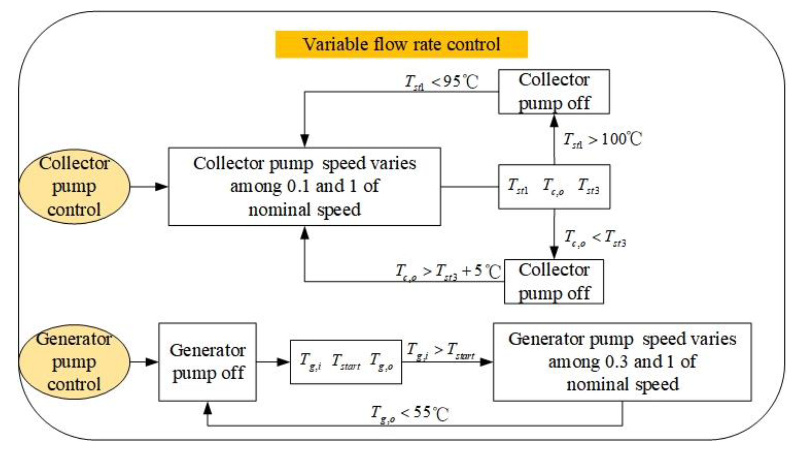
The control strategy of collector and generator pumps is demonstrated in Figure 2. The collector flow rate is controlled according to the setting temperature of the collector outlet, i.e., the flow rate of the collector hot water goes down automatically as the actual temperature of the collector outlet is lower than the set point one. The lowest collector flow rate is 10% of the nominal one to prevent thermal problems in the excessively low flow situation. Moreover, the collector pump is switched off when the temperature of the collector outlet is lower than the one of the storage tank bottom. It is restarted if the collector outlet temperature is 5 °C greater than the bottom temperature of the storage tank. In particular, the collector pump is turned off as the top layer temperature of storage tanks reaches 100 °C to avoid crystallization of absorption subsystems and is restarted as the temperature reaches less than 95 °C.
The generator pump is activated when the top layer temperature of storage tanks equals the activation temperature of absorption subsystems. The activation temperature is set to be 5 °C above the set point temperature of the generator hot water. Furthermore, the generator pump is turned off if the outlet temperature of the generator hot water falls to 55 °C because the temperature of hot water is too low to drive absorption subsystems from the experiment [8]. In another hand, the flow rate of the generator hot water is also controlled in terms of the setting temperature of the generator inlet. The minimal flow rate of the generator hot water is 30% of the rated one.

3. Model

The thermodynamic modeling of SASCHCS and model validation are described in this section.

3.1. Modeling of SASCHCS

The off-design model of SASCHCS was built based on the following assumption:
  • The system operates under quasi-steady state;
  • The cooling facility (absorption and compression subsystem) is adiabatic;
  • The evaporator and the condenser exit of compression subsystems are saturated;
  • The pressure loss of pipelines and heat exchangers is ignored;
  • The inlet hot water temperature of generator is equal to the top layer temperature of the storage tanks;
  • The inlet hot water of collectors is equal to the bottom layer temperature of storage tanks.

3.1.1. ETC and Storage Tank

The efficiency of ETC is calculated by the following expression [28]:
η e t c , i = Q e t c , i / A I i = F R [ τ α U L ( T e t c , i T a , i ) / I i ]
where F R is the heat removal factor and equal to:
F R = m c p A c U L [ 1 exp ( U L F A c m c p ) ]
U L is the overall heat loss coefficient and can be expressed by:
U L = U e + U t
where U e is header pipe edge loss coefficient and is expressed by:
U e = 2 π λ i n s L T ln ( D e x t / D int )
U t is the loss coefficient from the absorber tube to the ambient and can be defined as:
U t = 1 1 h g a + 1 h p g , r + h p g , c
The collector efficiency factor, F , is derived by [29]:
F = 1 / U L L [ 1 + U L / C b U L ( d + ( L d ) F ) + 1 C B + 1 h f π d ]
Furthermore, the thermal efficiency of collectors based on the operational period is:
η e t c = Δ t Q e t c , i d t Δ t A I i d t
The storage tank has three layers, and the energy balance of each layer is calculated below:
1 3 ρ V s t c p d T s t , i d t = m c c p ( T s t , i 1 T s t , i ) + m g c p ( T s t , i + 1 T s t , i ) h s t A s t ( T s t , i T a , i ) / 3
The initial temperature of storage tank is equal to the surrounding temperature. It is stated that layer 1 donates the top layer of the storage tank and layer three is the bottom layer.

3.1.2. Absorption Subsystem and Compression Subsystem

The off-design model of cooling subsystems (the absorption subsystem and the compression one) was developed in our previous study [30]. The model of the absorption subsystem was based on the characteristic equation.
The relationship of the generator heat transfer and the generator hot water flow rate can be expressed as [31]:
U A = ( m g m g , r a t e d ) 0.8 ( U A ) r a t e d
The cooling output of absorption subsystems is expressed as:
Q e , a s = s Δ Δ t α Q l o s s , a s = s Δ Δ t s Δ Δ t min
The parameter s is related to UA (multiplication of overall heat transfer coefficient and area in heat exchangers), and Δ Δ t is relevant to mean temperature of hot water, cooling water, and chilled water.
Δ Δ t min is calculated as follows [32]:
Δ Δ t min = 1.9 + 0.1 Δ Δ t
The COP of absorption subsystems is:
C O P a s = Q e , a s , i d t Q g , i d t
The off-design model of compressions is based on the lumped parameter method. As a result, the thermodynamic characteristic of its component is controlled by mass and energy conservation:
m i = m o
Q = m i h i m o h o = m c p Δ T = h A L M T D
The compressor work consumed by the SASCHCS is calculated by:
W = m c s ( h d i s , s h s u c ) / η s
Compared to the reference case (the cooling load is solely met by the compression subsystem), the energy saving of SASCHCS is:
E s a v e = Δ t ( W r e f , i W i ) d t
The COP of compression subsystems is:
C O P c s = Q e , c s , i d t W i d t

3.2. Model Validation and Case Study

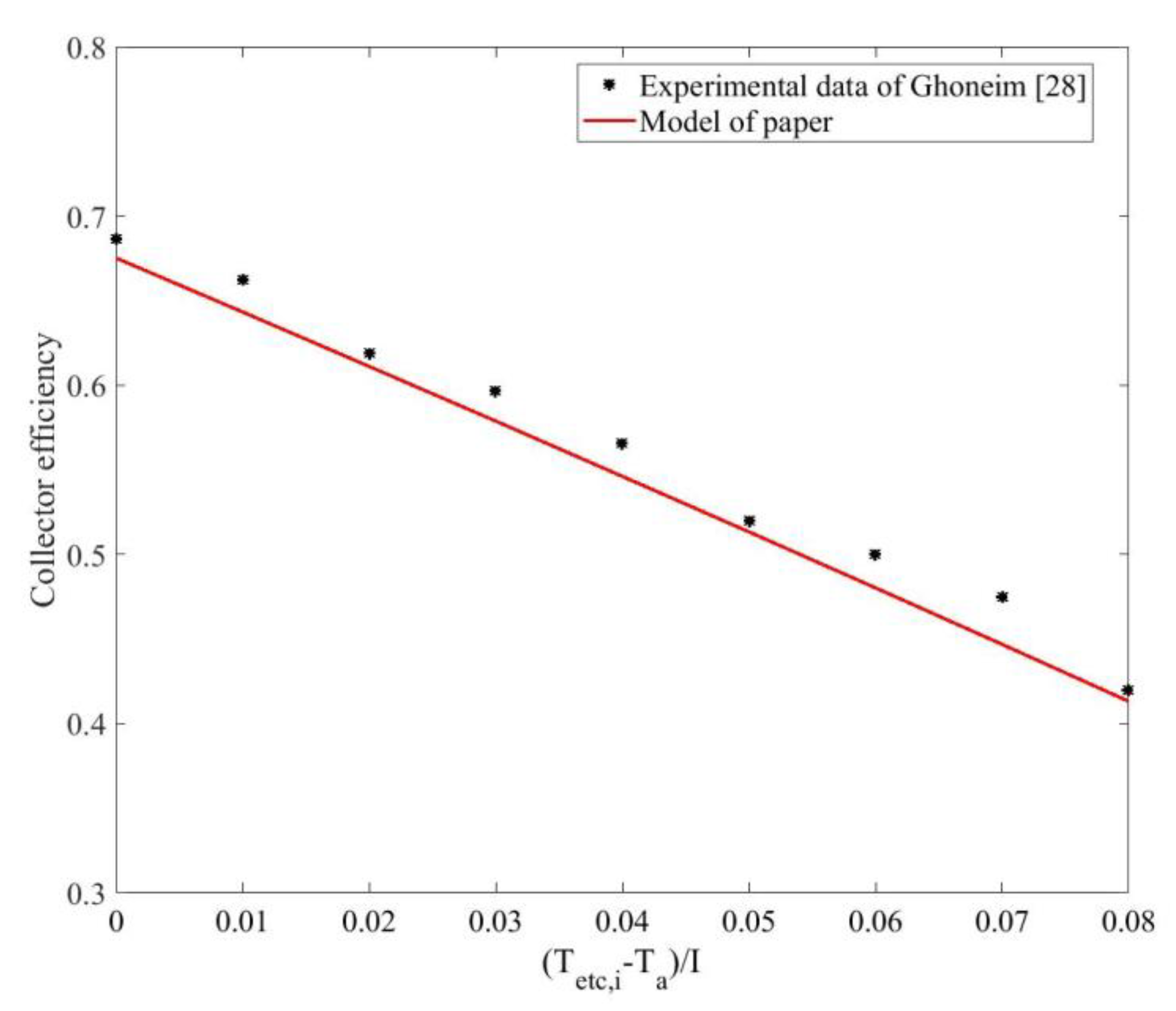
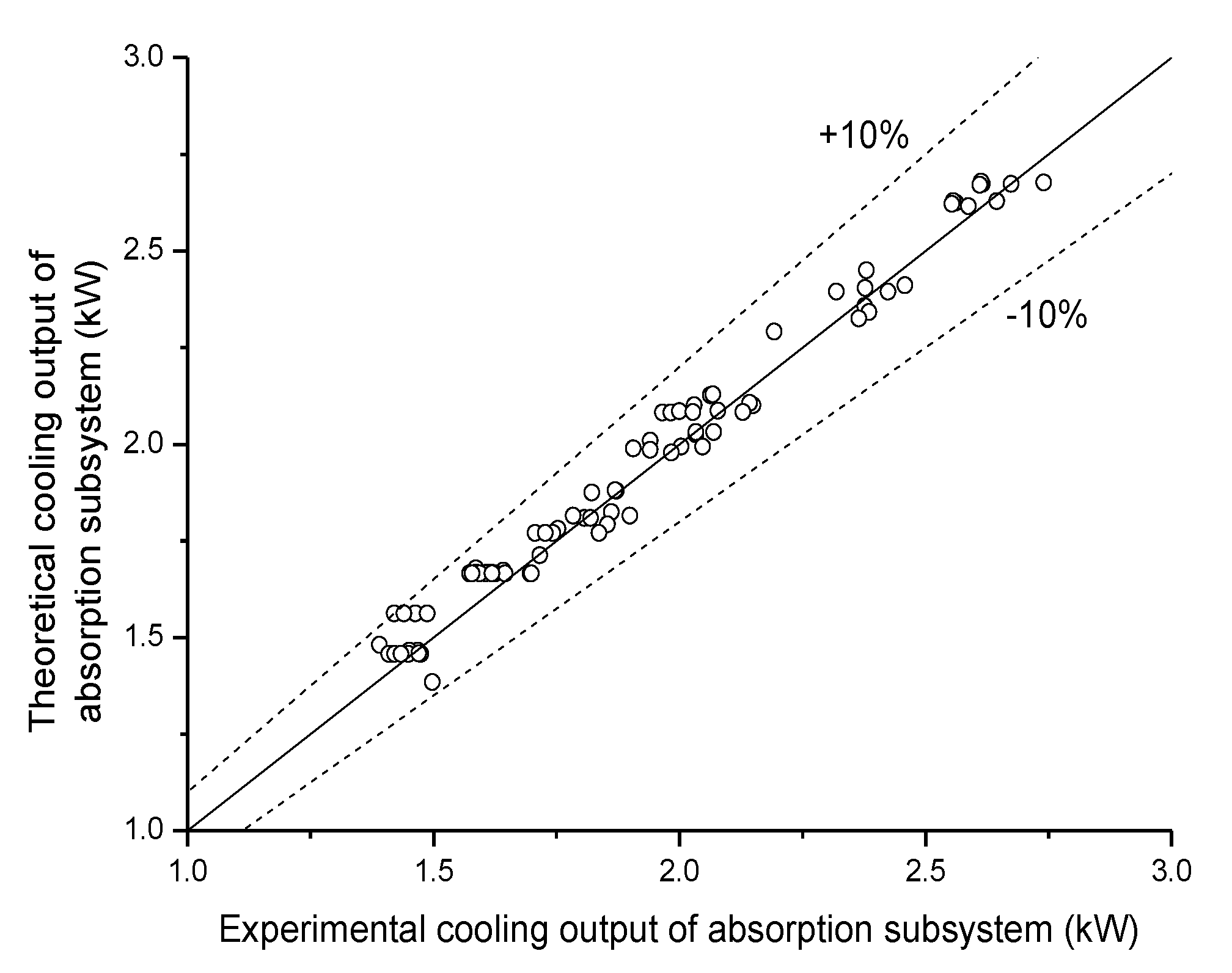
The ETC model was verified through the experimental data of Ghoneim [28]. A good agreement is displayed in Figure 3. The maximal deviation was 5.9%. In addition, the model validation of absorption subsystems and entire systems was implemented in our previous investigation by experiment [30]. As shown in Figure 4, the deviation regarding the model of absorption subsystems was within 10%. Additionally, it was demonstrated that the maximum relative error with respect to the model of entire systems was 3.58%, as shown in Table 1.
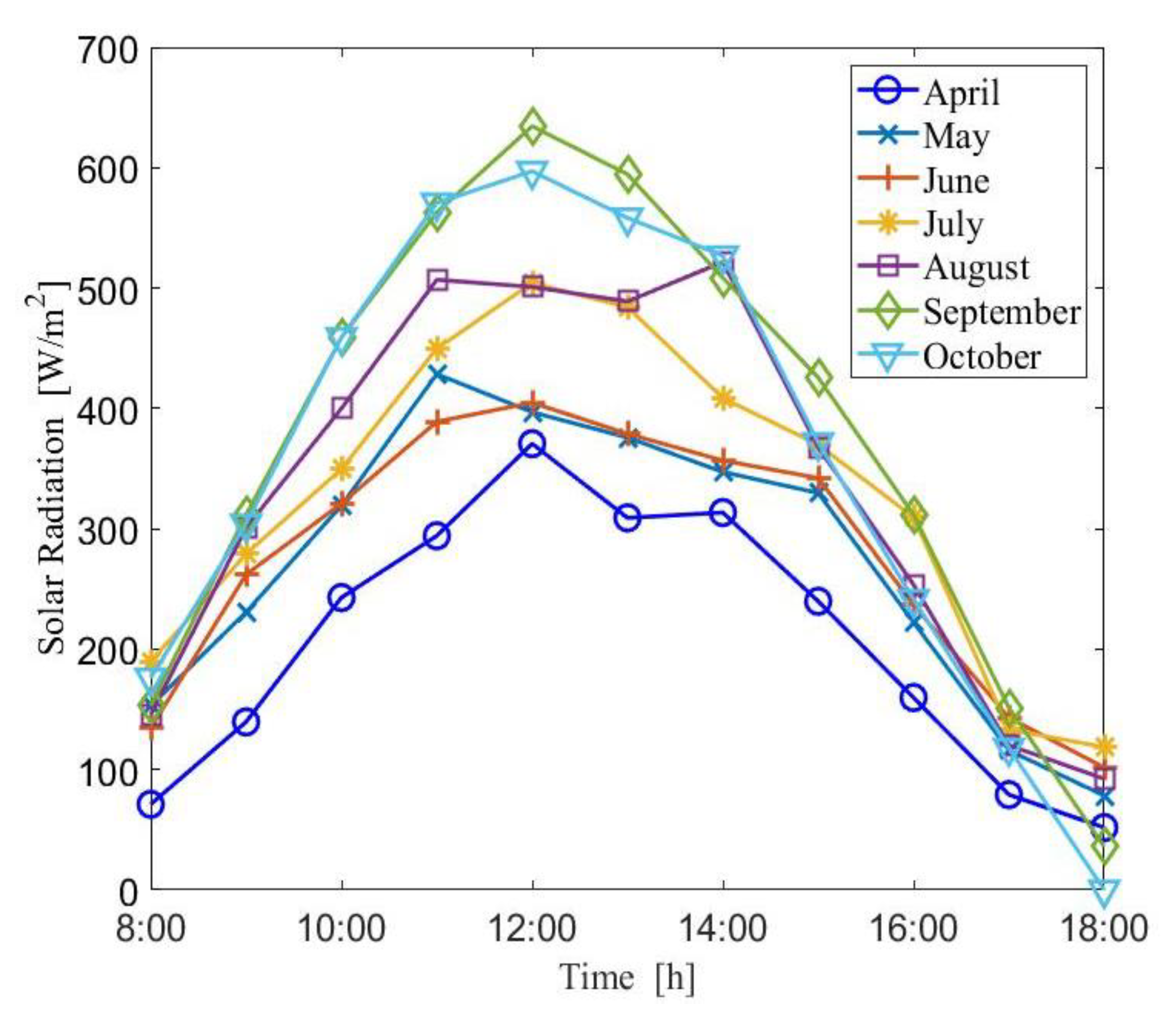
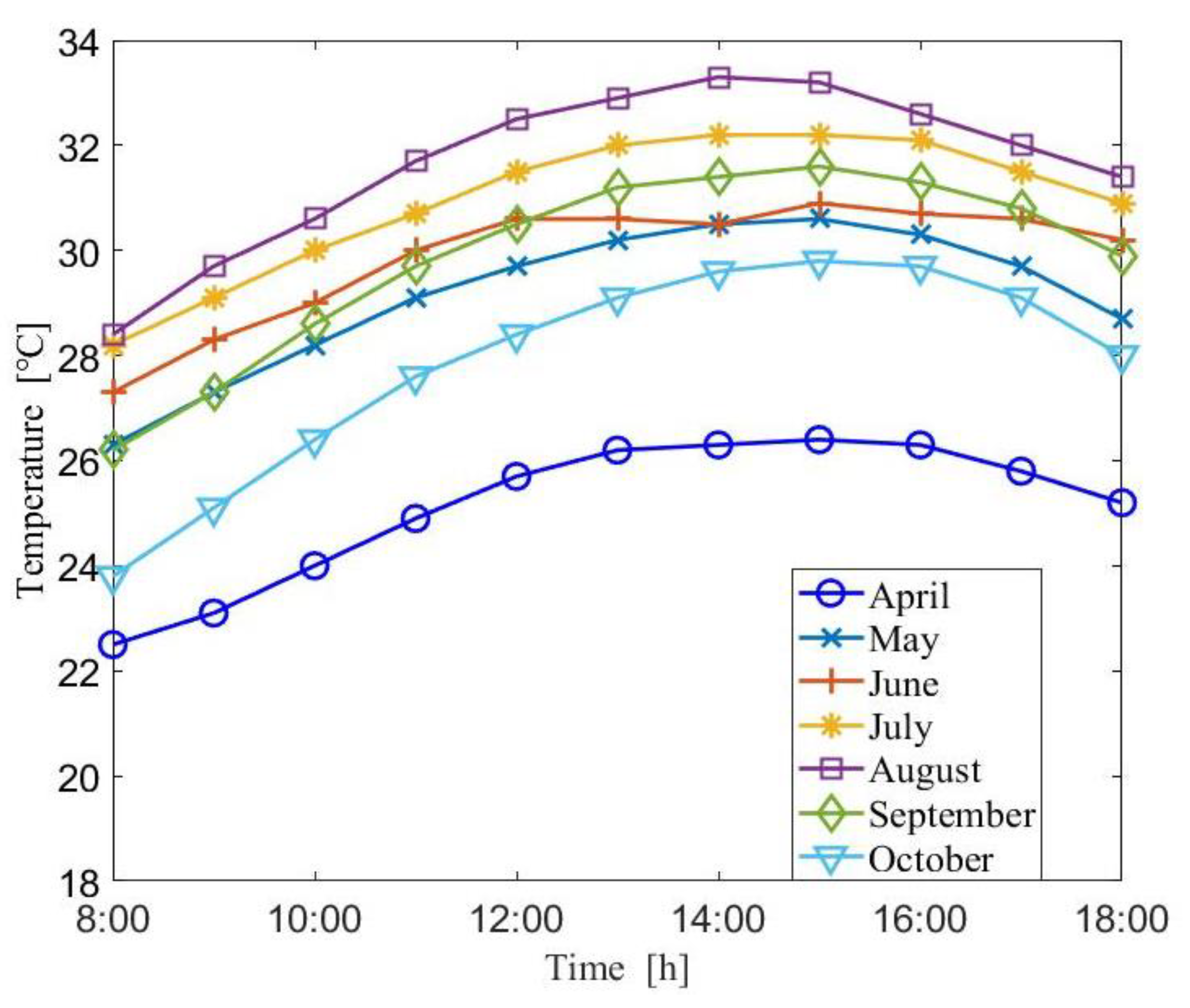
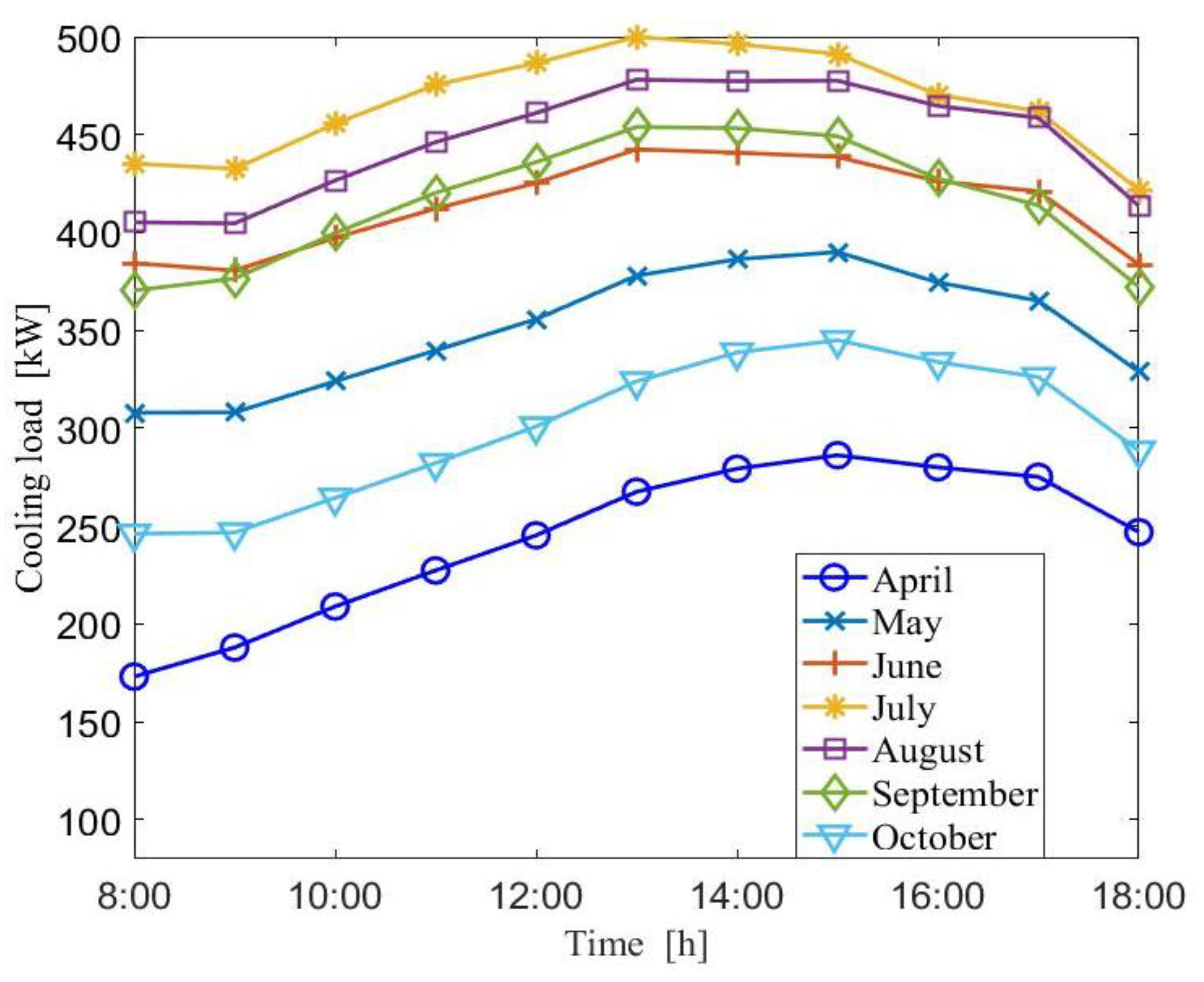
A case study was performed to assess the relationship of hot water setting temperature and the performance of SASCHCS. A typical high-rise office building located in subtropical Guangzhou was considered. Such buildings consist of ten floors, and the total area of the chosen building is 3840 m2 (area of each floor is 384 m2). As shown in Figure 5, the length and the width of every floor are 24 m and 16 m, respectively. There are ten rooms (seven offices, one meeting room, one rest room, as well as one machine room) on each story. It is noted that the machine room, the lift, and the staircase are excluded for cooling supply. Corresponding parameters of the above-mentioned building are listed in Table 2. The SASCHCS was employed to fulfill the cooling demand of office buildings. Design and operation parameters of SASCHCS are exhibited in Table 3. It is noted that the ETC was placed in the roof, and its installation area was designed to reasonably prevent the interference of each collector. Similar to the reference [33], parameters of absorption and compression subsystems were proportional to its nominal cooling capacity based on the size of our prototypes [8]. The typical monthly solar irradiance, the surrounding temperature, and the average data of annual measurement in our previous study [34] are exhibited in Figure 6 and Figure 7, respectively. The typical monthly data are the mean of monthly measurement data, i.e., the solar irradiance of 8:00 in August is the average of 8:00 data from 1 to 31 August. Consequently, such typical meteorological data can reflect the solar irradiance and the ambient temperature of the entire month more reasonably. The above-mentioned data were recorded by a small wireless weather station model named DAVIS Vantage Pro 2. Furthermore, the data were verified by the meteorological information center and the maximal deviation was less than 10%. As displayed in Figure 8, the cooling load of buildings was calculated by the software DeST [35] (DeST is the building energy consumption analysis software developed by Tsinghua University). It is the free software package that simulates the building environment and HVAC (heating, ventilation and air conditioning) systems. DeST platform is based on more than 10 years of research data by the Institute of Environment and Equipment, Department of Building Science and Technology, Tsinghua University. The model of entire facilities is solved in the MATLAB environment [36] with 1 min time steps. The thermodynamic property of working fluid and refrigerant was obtained by Refprop 9 [37]. In particular, the cooling demand of high-rise buildings exclusively offered by compression subsystems served as the reference case in the calculation of energy saving regarding the SASCHCS.

4. Results and Discussion

This section includes two topics: (1) the impact of hot water setting temperature and (2) the optimization of set point temperature in two hot water cycles based on the annual period by the genetic algorithm. It is noteworthy that the analysis of hot water setting temperature was based on the August data. Furthermore, the influence of set point temperature in hot water cycles was analyzed step by step to show the exact relationship between hot water setting temperature and facility performance. Firstly, the quasi-steady variation of hot water temperature and flow rate for two set point temperatures of hot water was analyzed. Secondly, the useful heat of collectors, COP, and cooling output of absorption subsystems for different hot water setting temperatures was illustrated. Thirdly, the monthly energy savings of SASCHCS for different set point temperatures of hot water cycles was elucidated.

4.1. Effect of Hot Water Setting Temperature

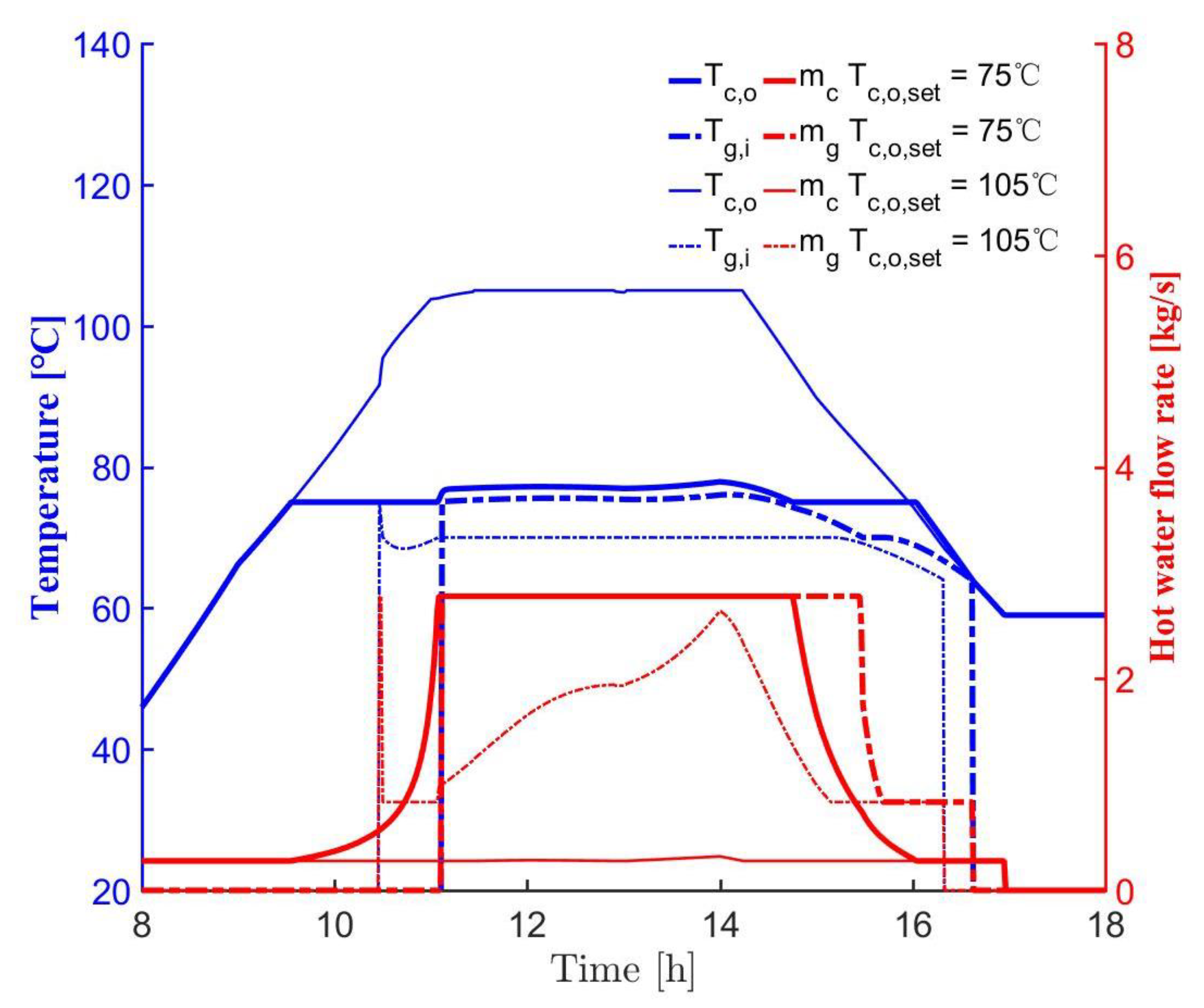
The variation of hot water temperature and flow rate with two set point temperatures of collector outlet is demonstrated in Figure 9. It is noteworthy that the setting inlet temperature of generator hot water was 70 °C. For the case in which the set point temperature of the collector outlet was 75 °C, it was observed that the collector flow rate went up gradually and maintained the nominal one from 11:05 to 14:45. Subsequently, the collector flow rate came down gradually and maintained the minimal one owing to the drop of solar irradiance. It was seen that the collector pump stopped at 16:57 because the collector outlet temperature was less than the bottom temperature of the storage tanks. Simultaneously, the collector outlet temperature kept the setting one with a 2 °C increase from 9:33 to 16:02. It dropped to 58 °C quickly in the end of the operation. Additionally, the generator pump was activated at 11:07, and the flow rate of generator hot water kept the rated one until 15:27. Subsequently, the flow rate of generator hot water went down quickly to the lowest one, and the generator pump was switched off at 16:37 since the hot water temperature of the generator outlet was less than 55 °C. Moreover, the hot water temperature of the generator inlet remained at 75 °C until 14:35 and reduced to 64 °C gradually in the end of the operation. For the case in which the set point temperature of the collector outlet was 105 °C, the collector flow rate nearly held the minimal one during the entire period. Besides, the collector outlet temperature attained the set point one in midday. It was found that the duration that the collector outlet temperature maintained the setting one reduced by 57% compared to the case in which the set point temperature of the collector outlet was 75 °C. The trend of collector outlet temperature for two setting temperatures overlapped after 16:00. Furthermore, the generator pump was activated 39 min earlier due to the faster improvement of top layer temperature in the storage tank. The sudden fall of generator hot water flow rate at the start of the generator pump was mainly attributed to the insufficient heat of the storage tank. Subsequently, the flow rate of generator hot water gradually approached the rated one at 14:00 and then decreased quickly to the lowest one. Furthermore, the generator inlet temperature almost held the set point one until 15:10. The generator pump was turned off at 16:19, which was 18 min earlier than the case in which the set point temperature of the collector outlet was 75 °C.
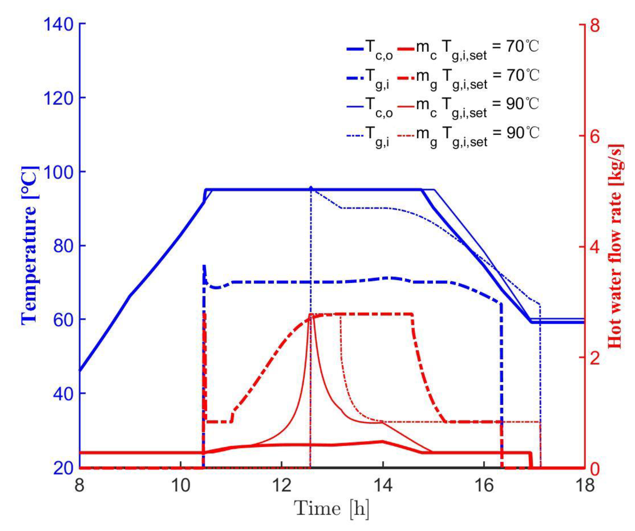
The variation of hot water temperature and flow rate with two set point temperatures of generator inlet is displayed in Figure 10. It is noteworthy that the setting temperature of the collector outlet was 95 °C. It was seen that collector flow rates for two setting temperatures of the generator inlet nearly overlapped except for the midday. The collector flow rate corresponding to 90 °C of T g , i , s e t became quadratic in this period owing to the strong solar irradiance and generator consumption. The collector outlet temperatures for two set point temperatures of the generator inlet were extremely similar except the duration when the collector outlet temperature kept the setting one for 90 °C of T g , i , s e t and extended 15 min. The flow rate of generator hot water for 90 °C of T g , i , s e t came down quickly after the activation of the generator pump. Similarly, its generator inlet temperature just maintained the set point one for 51 min, and the corresponding period was 20% of the one for 70 °C of T g , i , s e t . In addition, it was shown that the activation and the stop of the generator pump were delayed by 127 min and 46 min, respectively, for the case in which the setting temperature of the generator inlet was 90 °C.
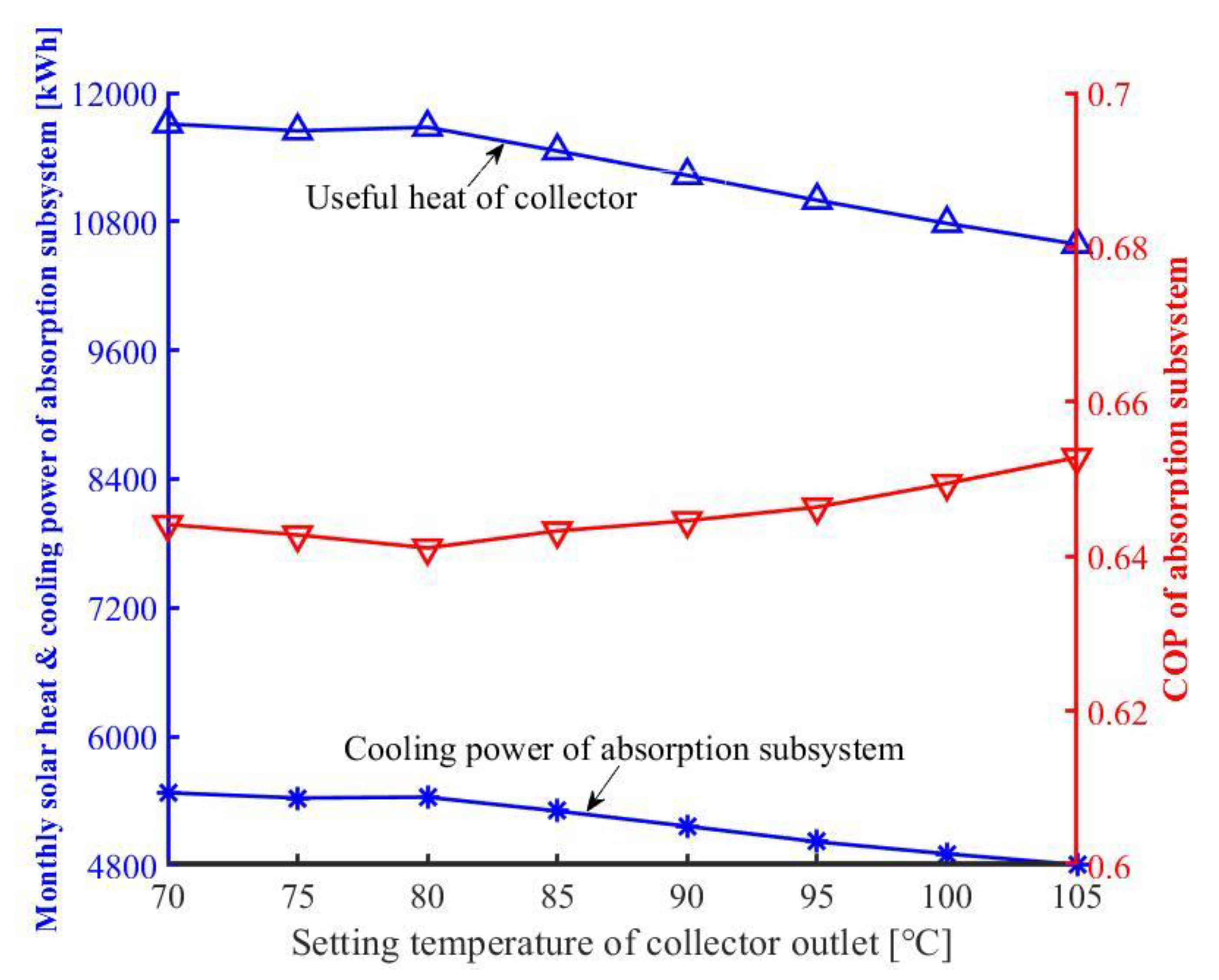
The impact of collector setting temperature with 70 °C set temperature of generator hot water is demonstrated in Figure 11. It was shown that trends of monthly useful heat in collectors and cooling capacity of absorption subsystems were similar. Both grew slightly as the set point temperature of the collector rose to 80 °C at first. It is known that the improvement of collector setting temperature decreases the collector flow rate so that the consequent drop in collector inlet temperature is favorable compared to the lower heat loss of collectors. Nevertheless, the excessive increase of collector setting temperature seriously deteriorated the performance, i.e., the monthly useful heat of collectors and the cooling capacity of absorption subsystems came down by 9.3% and 11.6%, respectively, if the collector set point temperature went up from 80 °C to 105 °C. The significant decrease of heat transfer coefficient caused by the excessive drop of collector flow rate led to the above-mentioned phenomenon. In addition, the COP of absorption subsystems with the set point temperature of collectors was quadratic as well. It enhanced by 1.8% when the collector setting temperature grew from 80 °C to 105 °C, which was led by the increased operation period of absorption subsystems. In general, the enhancement of the absorption subsystem COP was offset by the reduction of collector useful heat so that the excessive improvement of collector set point temperature was adverse for the solar cooling.
The effect of generator setting temperature with 95 °C collector set point temperature is displayed in Figure 12. It was seen that the rise of generator set point temperature decreased the solar heat, i.e., useful heat of the collector went down by 11.8% as the setting temperature of the generators went up by 30 °C. This was attributed to the enhanced generator set point temperature increasing the bottom layer temperature of the storage tanks. Thereby, the rise of collector inlet temperature lowered the amount of solar heat. However, the COP of absorption subsystem grew with the enhancement of generator setting temperature except when the set point temperature of the generator exceeded 85 °C. It was shown that the COP of the absorption subsystem rose by 10.1% as the generator setting temperature went up from 60 °C to 85 °C. The above-mentioned phenomenon was attributed to the influence of increased generator hot water temperature surpassing the one of decreased flow rate. Accordingly, there was an optimal setting temperature of the generator that maximized the cooling power of absorption subsystems. It was derived that the optimal generator set point temperature was 75 °C when the setting temperature of the collector outlet was 95 °C. Additionally, the cooling output of absorption subsystems with 75 °C generator setting temperature was 13.6% more than that in the 60 °C one. In general, appropriate improvement of generator set point temperature was beneficial for the solar cooling though the amount of solar heat went down slightly.
The monthly energy savings of SASCHCS for different setting temperatures of the collector outlet are shown in Figure 13. It was noted that the set point temperature of the generator was 70 °C. As expected, it was observed that the higher the cooling capacity of absorption subsystems was, the higher the energy saving of hybrid systems became from the August data. It was demonstrated that qualitative trends of energy saving with collector set point temperature based on different monthly data were similar. Furthermore, the energy saving trends were independent from the set point temperature of the collector as the collector setting temperature was higher than 85 °C for April, May, and June (months with low and moderate solar irradiance). This was illustrated by the fact that the hot water could not be heated to such excessively high temperatures by the weak solar irradiance, and even its flow rate was reduced to the minimal one. This also implied that the set point temperature of the collector outlet below 85 °C was effective for the hot water control from April to June. Moreover, the excessive enhancement of the collector setting temperature lowered the performance of SASCHCS, i.e., the monthly energy savings of May and June only fell by 7.6% and 7.9%, respectively. The above-mentioned effect became notable for the months with strong solar irradiance. For example, the monthly energy savings of July, August, September, and October came down by 15%, 10.7%, 10.1%, and 11%, respectively, if the collector setting temperature grew from 80 °C to 105 °C.
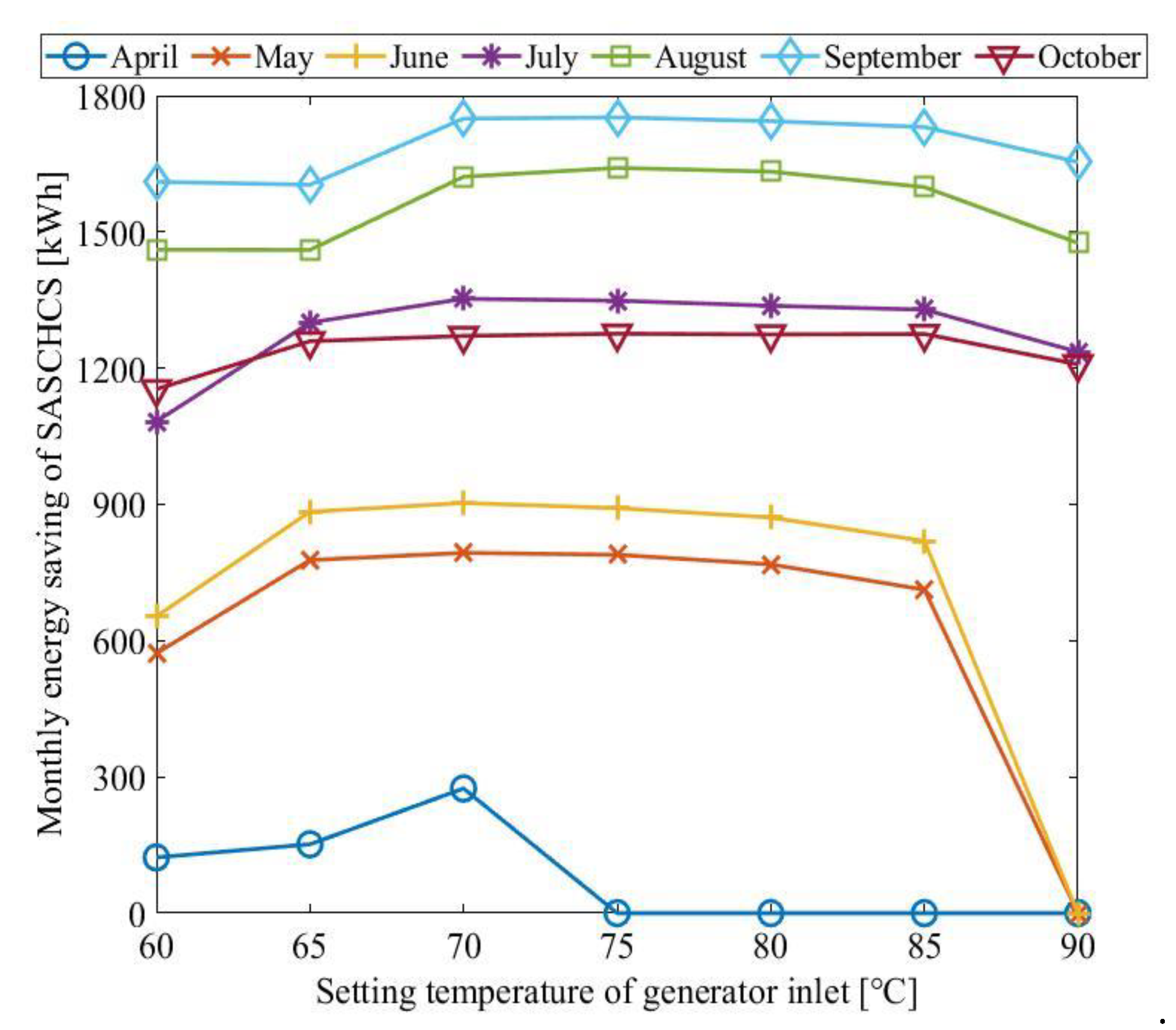
The monthly energy savings of SASCHCS for different setting temperatures of the generator inlet are exhibited in Figure 14. It is noteworthy that the collector set point temperature was 95 °C. The energy savings with set point temperature of the generator were quadratic in the entire period. In addition, it was found that the optimal setting temperature of generators was around 70–75 °C. The effect of the generator set point temperature on the performance was stronger for the months with weak and moderate solar irradiance, i.e., the monthly energy savings of April, May, June, July, August, September, and October rose by 123.7%, 38.7%, 38.2%, 25%, 12.3%, 8.8%, and 10.6%, respectively, when the setting temperature of generators went up from 60 °C to the optimal one. This was attributed to the rise of absorption subsystem COP by the increased generator hot water temperature dominating the performance of SASCHCS in April to June. In particular, the excessively high setting temperature of the generator deteriorated the solar cooling dramatically in April to June. The reason was that such a relatively high set point temperature of the generator was extremely difficult to reach by the weak solar irradiance, thus the duration of absorption subsystems went down dramatically.
The optimal collector setting temperature for different set point temperatures of the generator is listed at Table 4. It was shown that the optimal collector setting temperature associated with the certain set point temperature of generators was same regardless of month. Therefore, it can be said that the optimal setting temperature of the collector outlet was independent from the meteorological data. Furthermore, the optimal collector set point temperature strongly relied on the setting temperature of the generator, i.e., it was around 8–10 °C above the generator set point temperature. This was explained by the fact that the stratification of storage tanks, the critical factor of solar cooling, was kept by the synchronized growth of collector setting temperature. It should be noted that the amount of useful heat in collectors was subjected to remarkable reduction through the excessive rise of collector set point temperature.

4.2. Global Optimization of Setting Temperature in Two Hot Water Cycles

According to the analysis of Section 4.1, it is known that the appropriate increase of generator setting temperature is favorable for the COP of absorption subsystems. However, the improvement of generator set point temperature depends on the rise of collector setting temperature leading to the decrease of solar heat. Consequently, the global optimization of hot water set point temperature is extremely essential. Moreover, because the optimal setting temperature of hot water was shown to be independent from the meteorological data, the result of global optimization is convenient for the operation. Such optimization was done by the genetic algorithm function in the MATLAB environment. The maximum generation number and the population number were set as 50 and 20, respectively. The ranges of the collector and the generator setting temperature were 70–105 °C and 60–90 °C, respectively. Additionally, the maximal annual energy savings was employed as the objective function.
The annual performance of SASCHCS in the optimal case is shown in Table 5. It was shown that 71.6 °C of the collector setting temperature with 64.5 °C of the generator one was optimal for the annual operation of SASCHCS. The corresponding peak energy savings of SASCHCS were 8841.3 kWh/year, which was equivalent to 32.75 kWh/m2 of a specific one. Additionally, the annual collector efficiencies, the COP of absorption and compression subsystems, were 0.39, 0.63, and 4.86, respectively, in the optimal case. It was derived that the COP of compression subsystems enhanced by 14.1% due to the solar cooling compared to its nominal COP.

5. Conclusions

The influence of hot water setting temperature on the operation and the performance of SASCHCS was analyzed in detail based on the data of the entire cooling period in subtropical Guangzhou. The corresponding conclusions are summarized as follows:
  • Despite the fact that the COP of the absorption subsystem went up slightly with the increased hot water temperature, the excessive improvement of the collector setting temperature was harmful for the energy saving, since the serious reduction of heat transfer caused by the low flow rate notably decreased the amount of collector useful heat. It was derived that the daily cooling output of the absorption subsystem based on August data dropped by 11.6% as the collector set point temperature went up from 80 °C to 105 °C.
  • Although the enhanced temperature of generator hot water lowered the amount of solar heat, the appropriate rise of generator set point temperature was favorable for the solar cooling owing to the remarkable growth of COP in absorption subsystems, i.e., the daily cooling capacity of the absorption subsystem based on August data enhanced by 13.6% if the setting temperature of the generator grew from 60 °C to 75 °C.
  • The collector set point temperature should be 8–10 °C above the generator one in terms of the tradeoff of collector useful heat and absorption subsystem COP. In particular, the above-mentioned relationship is independent from the meteorological data.
  • It was demonstrated that a 71.6 °C collector setting temperature with a 64.5 °C generator one was optimal for the annual operation by the global optimization. The corresponding peak annual specific energy saving of SASCHCS was 32.75 kWh/m2. In addition, the annual collector efficiencies, the COP of absorption and compression subsystems, were 0.39, 0.63, and 4.86, respectively, in the optimal case.

Author Contributions

J.Z. contributes to data analysis and writing. Z.L. contributes to conceptualization and methodology. H.C. contributes to formal analysis. Y.X. contributes to the validation. All authors have read and agreed to the published version of the manuscript.

Funding

This work is supported by: (1) Natural Science Foundation of Guangdong Province under the contract No. 2018A030313310, (2) Guangzhou Municipal Science and Technology Project under the contract No. 201904010218, (3) State Key Laboratory of Compressor Technology under the contract No. SKL-YSJ201806, (4) Key Laboratory of Efficient and Clean Energy Utilization of Guangdong Higher Education Institutes under the contract No. KLB10004.

Conflicts of Interest

The authors declare no conflicts of interest.

Nomenclature

A area (m2) V volume (m3)
A c the outer surface area of absorber tube (m2) W compressor work (kW)
C O P coefficient of performance Δ T temperature difference (°C)
C b synthetic conductance W/(mK) Δ Δ t double difference of temperatures (°C)
C B bond conductance W/(mK) Greek symbols
c p specific heat (kJ/kgK) α absorptivity, distribution UA parameter
d diameter of the U-tube (m) η efficiency
D e x t external diameter of insulation (m) λ i n s header pipe insulation thermal conductivity (W/mK)
D int internal diameter of insulation (m) π pi
E s a v e energy saving (kWh) ρ density (kg/m3)
F fin efficiency of straight fin collector efficient factor τ transmissivity
F heat removal factor Subscripts
F R heat transfer coefficient (W/m2K)aambient
h specific enthalpy (kJ/kg) a s absorption subsystem
h f convection heat transfer coefficient between the fluid and the U-tube W/(m2K) a v g average
h g a convection heat transfer coefficient W/(m2K) c s compression subsystem
h p g , r radiation heat transfer coefficient, W/(m2K) d i s discharge
h p g , c heat transfer coefficient due to the conduction W/(m2K) e evaporator
I solar irradiance (W/m2) e t c evacuated tube collector
L the circumferential distance between the U-tubes (m) g generator
L M T D logarithmic mean temperature difference (°C) i inlet, current time
L T length of the header pipe per one U-tube (m) l o s s loss
m mass flow rate (kg/s)minminimum
Q heat load (kW) o outlet
t time r a t e d rated
T temperature (°C)refreference
U A multiplication of heat transfer coefficient and area (W/K) s isentropic
U e the heat loss coefficient from absorber tube to ambient W/(m2K) s u c suction
U L overall loss coefficient W/(m2K) s t storage tank
U t the edge loss coefficient of the header tube W/(m2K)

References

  1. Mohammed, O.W.; Yanling, G. Comprehensive Parametric Study of a Solar Absorption Refrigeration System to Lower Its Cut In/Off Temperature. Energies 2017, 10, 1746. [Google Scholar] [CrossRef] [Green Version]
  2. Perez-Lombard, L.; Ortiz, J.; Pout, C. A review on buildings energy consumption information. Energy Build. 2008, 40, 394–398. [Google Scholar] [CrossRef]
  3. Xu, Z.; Wang, R. Comparison of CPC driven solar absorption cooling systems with single, double and variable effect absorption chillers. Sol. Energy 2017, 158, 511–519. [Google Scholar] [CrossRef]
  4. Noro, M.; Lazzarin, R. Solar cooling between thermal and photovoltaic: An energy and economic comparative study in the Mediterranean conditions. Energy 2014, 73, 453–464. [Google Scholar] [CrossRef]
  5. Colmenar-Santos, A.; Vale-Vale, J.; Borge-Diez, D.; Requena-Pérez, R. Solar thermal systems for high rise buildings with high consumption demand: Case study for a 5 star hotel in Sao Paulo, Brazil. Energy Build. 2014, 69, 481–489. [Google Scholar] [CrossRef]
  6. Li, Z.; Jing, Y.; Liu, J. Thermodynamic study of a novel solar LiBr/H2O absorption chiller. Energy Build. 2016, 133, 565–576. [Google Scholar] [CrossRef]
  7. Xu, Y.; Jiang, N.; Pan, F.; Wang, Q.; Gao, Z.; Chen, G. Comparative study on two low-grade heat driven absorption-compression refrigeration cycles based on energy, exergy, economic and environmental (4E) analyses. Energy Convers. Manag. 2017, 133, 535–547. [Google Scholar] [CrossRef]
  8. Yu, J.; Li, Z.; Chen, E.; Xu, Y.; Chen, H.; Wang, L. Experimental assessment of solar absorption-subcooled compression hybrid cooling system. Sol. Energy 2019, 185, 245–254. [Google Scholar] [CrossRef]
  9. Li, Z.; Liu, L. Economic and environmental study of solar absorption-subcooled compression hybrid cooling system. Int. J. Sustain. Energy 2019, 38, 123–140. [Google Scholar] [CrossRef]
  10. Li, Z.; Liu, L.; Jing, Y. Exergoeconomic analysis of solar absorption-subcooled compression hybrid cooling system. Energy Convers. Manag. 2017, 144, 205–216. [Google Scholar] [CrossRef]
  11. Jing, Y.; Li, Z.; Chen, H.; Lu, S.; Lv, S. Exergoeconomic design criterion of solar absorption-subcooled compression hybrid cooling system based on the variable working conditions. Energy Convers. Manag. 2019, 180, 889–903. [Google Scholar] [CrossRef]
  12. Zamfir, E.; Bǎdescu, V.; Badescu, V. Different strategies for operation of flat-plate solar collectors. Energy 1994, 19, 1245–1254. [Google Scholar] [CrossRef]
  13. Csordas, G.; Brunger, A.; Hollands, K.; Lightstone, M. Plume entrainment effects in solar domestic hot water systems employing variable-flow-rate control strategies. Sol. Energy 1992, 49, 497–505. [Google Scholar] [CrossRef]
  14. Rehman, H.U.; Hirvonen, J.; Sirén, K. Design of a Simple Control Strategy for a Community-size Solar Heating System with a Seasonal Storage. Energy Procedia 2016, 91, 486–495. [Google Scholar] [CrossRef]
  15. Araújo, A.; Silva, R.; Pereira, V. Solar thermal modeling for rapid estimation of auxiliary energy requirements in domestic hot water production: On-off versus proportional flow rate control. Sol. Energy 2019, 177, 68–79. [Google Scholar] [CrossRef]
  16. Bava, F.; Furbo, S. Impact of different improvement measures on the thermal performance of a solar collector field for district heating. Energy 2018, 144, 816–825. [Google Scholar] [CrossRef] [Green Version]
  17. Tehrani, S.S.M.; Taylor, R.A. Off-design simulation and performance of molten salt cavity receivers in solar tower plants under realistic operational modes and control strategies. Appl. Energy 2016, 179, 698–715. [Google Scholar] [CrossRef]
  18. Yilmazoglu, M.Z. Effects of the selection of heat transfer fluid and condenser type on the performance of a solar thermal power plant with technoeconomic approach. Energy Convers. Manag. 2016, 111, 271–278. [Google Scholar] [CrossRef]
  19. Camacho, E.; Gallego, A. Optimal operation in solar trough plants: A case study. Sol. Energy 2013, 95, 106–117. [Google Scholar] [CrossRef]
  20. Brodrick, P.G.; Brandt, A.R.; Durlofsky, L.J. Operational optimization of an integrated solar combined cycle under practical time-dependent constraints. Energy 2017, 141, 1569–1584. [Google Scholar] [CrossRef]
  21. Qu, M.; Yin, H.; Archer, D.H. A solar thermal cooling and heating system for a building: Experimental and model based performance analysis and design. Sol. Energy 2010, 84, 166–182. [Google Scholar] [CrossRef]
  22. Calise, F.; D’Accadia, M.D.; Vanoli, R. Dynamic simulation and parametric optimisation of a solar-assisted heating and cooling system. Int. J. Ambient. Energy 2010, 31, 173–194. [Google Scholar] [CrossRef]
  23. Petela, K.; Manfrida, G.; Szlek, A. Advantages of variable driving temperature in solar absorption chiller. Renew. Energy 2017, 114, 716–724. [Google Scholar] [CrossRef]
  24. Weber, C.; Berger, M.; Mehling, F.; Heinrich, A.; Núñez, T. Solar cooling with water–ammonia absorption chillers and concentrating solar collector—Operational experience. Int. J. Refrig. 2014, 39, 57–76. [Google Scholar] [CrossRef]
  25. Shirazi, A.; Pintaldi, S.; White, S.D.; Morrison, G.L.; Rosengarten, G.; Taylor, R.A. Solar-assisted absorption air-conditioning systems in buildings: Control strategies and operational modes. Appl. Therm. Eng. 2016, 92, 246–260. [Google Scholar] [CrossRef]
  26. Li, Z.; Chen, E.; Jing, Y.; Lv, S. Thermodynamic relationship of subcooling power and increase of cooling output in vapour compression chiller. Energy Convers. Manag. 2017, 149, 254–262. [Google Scholar] [CrossRef]
  27. Chen, E.; Li, Z.; Yu, J.; Xu, Y.; Yu, Y. Experimental research of increased cooling output by dedicated subcooling. Appl. Therm. Eng. 2019, 154, 9–17. [Google Scholar] [CrossRef]
  28. Ghoneim, A.A. Performance optimization of9 evacuated tube collector for solar cooling of a house in hot climate. Int. J. Sustain. Energy 2018, 37, 193–208. [Google Scholar] [CrossRef]
  29. Ma, L.; Lu, Z.; Zhang, J.; Liang, R. Thermal performance analysis of the glass evacuated tube solar collector with U-tube. Build. Environ. 2010, 45, 1959–1967. [Google Scholar] [CrossRef]
  30. Li, Z.; Yu, J.; Chen, E.; Jing, Y. Off-Design Modeling and Simulation of Solar Absorption-Subcooled Compression Hybrid Cooling System. Appl. Sci. 2018, 8, 2612. [Google Scholar] [CrossRef] [Green Version]
  31. Miao, D. Simulation Model of a Single-Stage Lithium Bromide-Water Absorption Unit; NASA Technical Paper 1296; NASA: Washington, DC, USA, 1978.
  32. Arnavat, M.P.; López-Villada, J.; Bruno, J.C.; Coronas, A. Analysis and parameter identification for characteristic equations of single- and double-effect absorption chillers by means of multivariable regression. Int. J. Refrig. 2010, 33, 70–78. [Google Scholar] [CrossRef]
  33. Chen, H.; Li, Z.; Xu, Y. Evaluation and comparison of solar trigeneration systems based on photovoltaic thermal collectors for subtropical climates. Energy Convers. Manag. 2019, 199, 111959. [Google Scholar] [CrossRef]
  34. Li, Z.; Ye, X.; Liu, J. Performance analysis of solar air cooled double effect LiBr/H2O absorption cooling system in subtropical city. Energy Convers. Manag. 2014, 85, 302–312. [Google Scholar] [CrossRef]
  35. De ST. Available online: http://update.dest.com.cn/ (accessed on 12 October 2019).
  36. MATLAB. Available online: https://ww2.mathworks.cn/ (accessed on 12 October 2019).
  37. Refprop9. Available online: http://www.nist.gov/srd/nist23.cfm (accessed on 12 October 2019).
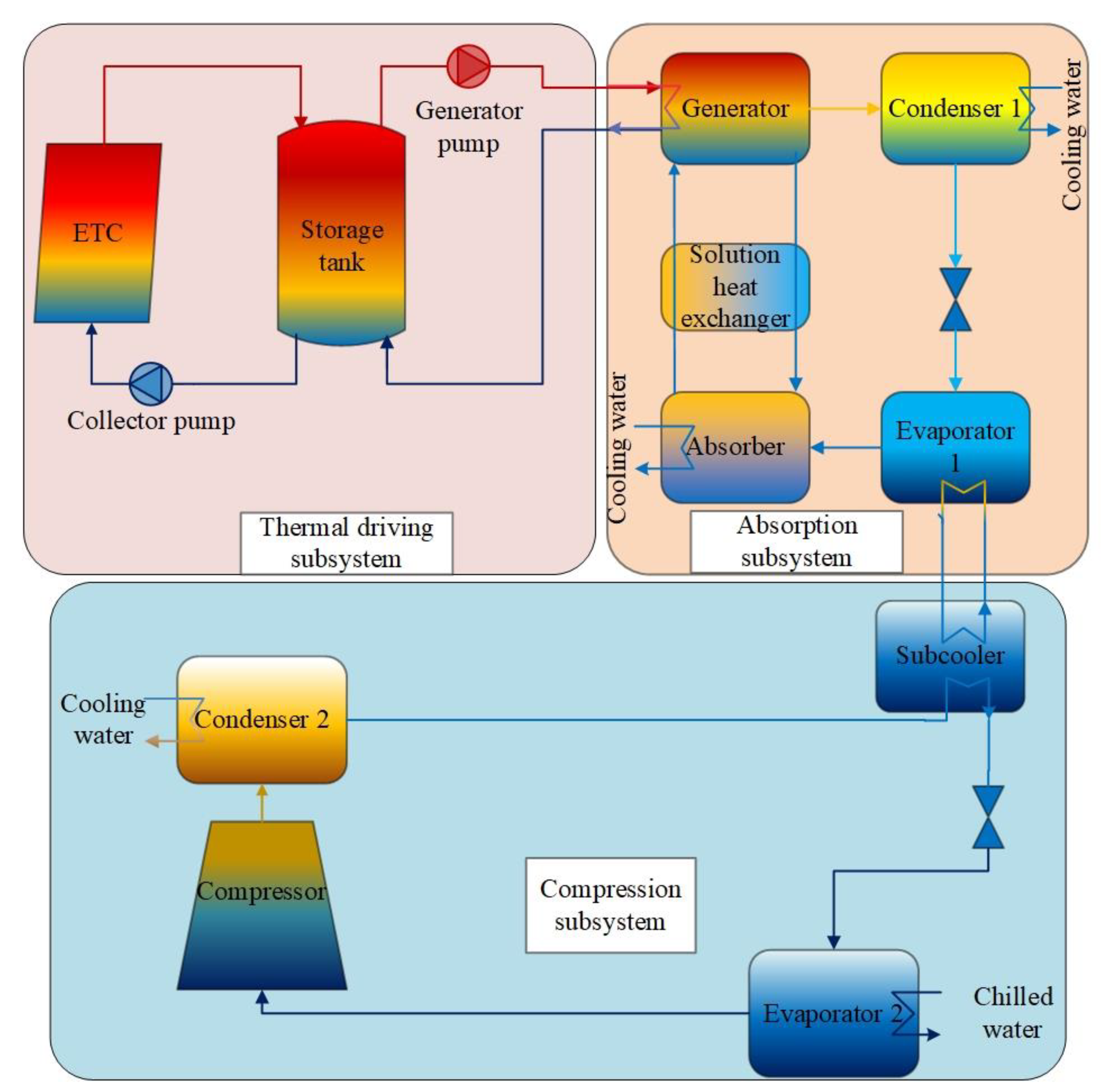
Figure 1. Schematic of solar absorption-subcooled compression hybrid cooling system (SASCHCS).
Applsci 10 00258 g001
Figure 2. Control strategies for collector and generator pumps.
Applsci 10 00258 g002
Figure 3. Validation of evacuated tube collector (ETC) model.
Applsci 10 00258 g003
Figure 4. Model validation of absorption subsystem.
Applsci 10 00258 g004
Figure 5. Layout and orientation of building.
Applsci 10 00258 g005
Figure 6. Solar radiation.
Applsci 10 00258 g006
Figure 7. Ambient temperature.
Applsci 10 00258 g007
Figure 8. Cooling load.
Applsci 10 00258 g008
Figure 9. Hot water temperature and flow rate for different T c , o , s e t .
Applsci 10 00258 g009
Figure 10. Hot water temperature and flow rate for different T g , i , s e t .
Applsci 10 00258 g010
Figure 11. Impact of setting temperature of collector outlet.
Applsci 10 00258 g011
Figure 12. Impact of set point temperature of generator inlet.
Applsci 10 00258 g012
Figure 13. Energy saving for different collector setting temperatures.
Applsci 10 00258 g013
Figure 14. Energy saving for different generator setting temperatures.
Applsci 10 00258 g014
Table 1. Model validation of compression subsystem.
ParameterValue
ModelExperimentRelative Error
T c w , c s , o (°C)31.5332.73.58%
T c h w , c s , o (°C)109.91.01%
T d i s (°C)59.6859.40.47%
Δ T s u b (°C)14.2814.11.28%
Table 2. Load simulation assumptions and schedules for the case study.
ParameterValue
Floor area384 m2
Floor height3.3 m
Floor number10
Total area3840 m2
Cooling seasonFrom April to October
Air conditioning operation period8:00–18:00
Window-to-wall ratio0.5
Space temperature control22–26 °C
Space humidity control40–60%
Occupant density in office/meeting room/rest room/corridor and lobby0.1/0.3/0.3/0.2 person/m2
Sensible heat load regarding people in office/meeting room/rest room/corridor and lobby66/61/62/58 W/person
Humidity load regarding people in office/meeting room/rest room/corridor and lobby0.102/0.109/0.068/0.184 kg/(Hr·person)
Lighting power density9 W/m2
Electrical equipment power density in office/meeting room/rest room/corridor and lobby18/11/5/11 W/m2
Ventilation rate1 vol/h
Heat transfer coefficients of walls/windows/roof1.081/2.7/0.812 W/(m2K)
Table 3. Operation parameters of SASCHCS.
ParametersUnitValue
ETC→
Aperture aream2270
Outer diameter of absorber tubem0.037
Thickness of absorber tubem0.0012
Outer diameter of glass tubem0.047
Thickness of glass tubem0.0012
Outer diameter of U-tubem0.008
Thickness of air layerm0.001
Thickness of copper finm0.0006
Length of the header pipe per one U-tubem1.2
Nominal hot water flow of collectorkg/s2.78
Tilted angle 20
Storage tank
Aspect ratio 3.5
Heat loss coefficientW/(m2 K)0.83
Nominal hot water flow of generatorkg/s2.78
Volume of storage tankm32.7
Absorption subsystem
Flow rate of cooling water in condenser 1/absorber/subcoolerkg/s2.5/2.2/2.9
Inlet temperature of cooling water°C32
Nominal coefficient of performance (COP) 0.73
Compression subsystem
Flow rate of cooling water in condenser 2kg/s27.3
Inlet temperature of cooling water°C32
Inlet/outlet temperature of chilled water°C12/7
Isentropic efficiency of compressor 0.7
Nominal COP 4.26
Table 4. Optimal T c , o , s e t for different T g , i , s e t .
T g , i , s e t (°C)Optimal Collector Outlet Set Temperature (°C)
AprMayJunJulAugSeptOct
6575757575757575
75-838383838483
85-949494949594
Table 5. Annual performance of SASCHCS in the optimal case.
Q e t c (kWh) Q e , a s (kWh) E s a v e (kWh) η e t c C O P a s C O P c s
73310.730854.78841.30.390.634.86