Abstract
With the large-scale and complexity of ship propulsion shafting, it is more difficult to analyze and control the torsional vibration of shafting. Therefore, an effective control method for the torsional vibration of shafting is of great significance in the field of ship engineering. The main strategy of torsional vibration control adopted in this paper is to keep the natural frequency of a shaft system away from the excitation frequency through structural modifications. In addition, because the basic parameters of much of the equipment in engineering applications cannot be changed, this restriction cannot be ignored when seeking solutions related to structural modifications. This paper studies the partial eigenvalue assignment for the torsional vibration control of complex ship propulsion shafting using the gradient flow method, which can shift a “dangerous” natural frequency to a safe value, while satisfying complex physical constraints. The models of a ship propulsion system and a diesel generator set are established to demonstrate several different desired modification schemes and constraint conditions in practice. In particular, close frequencies are shifted. The numerical simulation results demonstrate that it is effective and feasible to make a partial frequency assignment of torsional vibration, which provides a reliable approach for the control of torsional vibration for complex shaft systems in practical engineering.
1. Introduction
In recent years, with the improvement of ship power and the widespread use of large-scale and complex shafting systems, the vibration problem of shafting systems becomes more and more serious. The torsional vibration of a shafting system is one of the main causes of shafting fracture and other faults, which has attracted wide attention. The dynamic performance of torsional vibration is one of the main aspects to guarantee the productivity and safety of machines and structures, and thus has great economic and social significance. However, there are many situations in which the structural design cannot meet the desired structural dynamic characteristics so that some accidents happen in serious cases, especially shaft breakage. Structural modifications (SMs) are known to be a very important technique to improve the dynamic characteristics of a structure in the form of fundamental structural parameters (such as mass, stiffness, and damping) to avoid resonance or the creation of a node on the system at a certain frequency. Additionally, SMs are also a procedure aimed at identifying the changes needed and determining the values of the physical parameters of a structure to achieve desirable dynamic characteristics (usually modal properties such as natural frequencies, mode shapes, and frequency response). Several theories and many algorithms have been established to solve SMs as a direct problem and as an inverse problem. Early studies about direct structural modification are mainly based on small modifications, localized modifications, and modal approximation [1]. The first useful method for structural modification was formulated and broaden by many researchers [2], which was based on a matrix perturbation approach to get an approximate solution for the modal properties of the modified structure. However, the limitation of the perturbation approach is that the modification should be small in order to get an accurate solution. Other methods such as the analytical approach of structural modification by adding different mass and stiffness attachments [3,4,5], the Rayleigh quotient method [6], and the sensitivity analysis method [7,8] were applied as useful tools for structural modification.
The inverse problem, being more complex, tries to identify, in the frame of a given set of possible locations, the most appropriate modifications required to obtain the desired dynamic behavior [9]. One major objective of doing that is to keep the frequency of excitation away from a natural frequency so that a large structural response can be prevented. The methods for inverse structural modifications are based on physical model parameters [10,11,12] (such as the mass matrix, stiffness matrix, and damping matrix) and experimental modal analysis [13,14,15,16] (e.g., natural frequencies and modal shapes derived from modal testing or directly by the frequency response function) by either passive procedues, active procedures, or combining the above two procedures in a hybrid approach. There are large numbers of published papers in the literature describing the study of inverse problems, and therefore only a brief introduction to some major ones is given as follows.
Hu et al. [17] studied the problem of natural frequency assignment for mass-chain systems with inertias to determine whether an arbitrary set of positive numbers can be assigned as the natural frequencies of a chain of n masses. The solution and solvability condition for the inverse problem of linear undamped gyroscopic systems were presented by Yuan and Dai [18], and the results were applied to model updating. A geared rotor-bearing system was designed and tested by Tsai et al. [19] to validate the method for solving the inverse structural modification using the measured receptances. Liu et al. presented the strategy for the torsional vibration control of shaft systems based on the measured torsional receptances of the system [20].
All of these above approaches can effectively change some natural frequencies of a structure to targeted values. However, a problem has received less attention: the undesired changes of the other natural frequencies of the original structure as a result of the modifications, which is known as the frequency “spill-over” phenomenon. In order to overcome this problem, many scholars have studied this challenging research topic using the partial eigenvalue assignment problem, which aims to assign some natural frequencies to desired locations and keep all the other frequencies unchanged.
Partial frequency assignment can be achieved fairly easily by means of active control. Many researchers [21,22,23,24,25] studied this problem based on the stiffness matrix perturbation, the receptance measurements, or a combination of these two. Bai et al. [26,27,28] presented hybrid optimization methods for the robust and minimum norm partial quadratic eigenvalue assignment problems, which are suitable for systems with and without time delays. Based on [28], Liu et al. [29] proposed a modified conjugate gradient method to solve the problem only using receptance. Compared with the hybrid method given by Ram et al. [22] for the single-input systems, Bai [30] solved the multi-input partial quadratic eigenvalue assignment problem using a multi-step hybrid method combining the system matrices and the receptance measurements. Ram and Mottershead [31] described a new theory that was applicable to both the single-input-multiple-output and multiple-input-multiple-output vibration control of practical engineering structures using the receptance method. Zhang et al. [32,33,34] presented some algorithms to solve the partial eigenvalue assignment for high-order systems by single-input control or multi-input control. Many researchers [35,36,37] also studied this problem based on various feedback signals, such as the sound pressure signal, displacement feedback signal, and acceleration feedback signal.
In fact, considering the low cost and maintenance required for system stability, it is expected to achieve a partial eigenvalues (or natural frequencies) assignment, depending on passive control or passive structural modification. However, this is a far more difficult task and challenge; as a result, few research papers have been introduced to solve this problem.
In recent years, some researchers have tried to study partial frequency assignments via passive control, which is more challenging but more useful than active control. Passive structural modifications of mass-spring systems for the partial assignment of natural frequencies were addressed by Ouyang and Zhang [38], and two different methods were presented. Compared with the work in [38], Belotti et al. [39] proposed a new method to assign a subset of natural frequencies of general structures with low spill-over, and optimal structural modifications were determined through a three-step procedure considering both the prescribed eigenvalues and the feasibility constraints.
The method mentioned above in [38] was shown to work for only simple systems and small modifications. In this paper, the main objective is a further theoretical development of the passive partial frequency assignment methods proposed by the research group of one of the authors (Ouyang and Zhang [38]). Its practical application to realistic large systems, which involves more stringent physical constrains, and its feasibility to bigger frequency modifications are investigated. In addition, it is for the first time demonstrated that the assignment of close eigenvalues can be achieved through the theory of structural modification.
In this paper, a simplified model of a “real” marine diesel engine propulsion system and a complex branched shaft system of a diesel generator set for torsional vibration control are investigated to achieve the partial assignment of natural frequencies. Various operation conditions and practical restrictions are considered. Additionally, modifications for assigning close eigenvalues and bigger frequencies are designed to show the strong applicability of the method. The outline of this paper is as follows. In Section 2, the passive control method is presented. The desired modifications and the achieved results of the simplified “real” propulsion system with different physical constraints at various operating conditions are analyzed in Section 3. Section 4 deals with the assignment of close eigenvalues of a complex branched shaft system. Finally, some conclusions are drawn in Section 5.
2. Theoretical Development
2.1. The Problem Description
Suppose that a general n-degree-of-freedom vibration system consists of mass matrix and stiffness matrix . The damping matrix is neglected, as the damping of many practical systems is small, such as a shafting that undergoes torsional vibration concerned in this paper.
The undamped vibration system is described by a second-order ordinary differential equation as follows:
In general, is a symmetric and positive definite matrix, and is a symmetric and positive-semidefinite matrix. is the displacement vector, and is the acceleration vector.
Assuming the displacement vector and , and substituting them in Equation (1) yields
According to the Cholesky decomposition, mass matrix can be defined as . And then supposing , Equation (2) can be turned into:
where
so that has the same eigenvalues as the original system .
2.2. Construction of a Real Smmetric Matrix with All Expected Eigenvalues
In order to achieve the goal of partial assignment of the natural frequencies of the system, the system eigenvalues are denoted by . It is expected that a set of original system eigenvalues are replaced by the desired eigenvalues after accomplishing some related system mass and stiffness modifications. Furthermore, contains all the eigenvalues that remain unchanged. is the mass-normalized eigenvector matrix of Equation (2) corresponding to .
From the spectral decomposition theorem of symmetric matrices, a new matrix can be expressed as follows:
which contains the desired eigenvalues of the modified system and has the same eigenvectors as . and are the normalized eigenvector matrices of Equation (3), corresponding to and , respectively.
Based on the relationships of and , Equation (5) can be changed to:
However, it should be noted that is not easy to determine in practice, although it contains all the desired eigenvalues; that is, it is difficult to find the relationship between and the mass and stiffness matrices. Then, it is useful to reconstruct a matrix , which is in the same matrix form as so that it can be easily used to obtain the system matrices of new mass-spring systems. Besides, many machines have fixed or complex structural configurations, which are not easy to change or even not allowed to be changed. So, there are many special physical limitations to structural modifications in engineering applications. In order to solve this problem, it is critical to find a method that can not only reconstruct a matrix , but also satisfy special constrains. In this paper, the method introduced in Ref. [40] will be applied to solve this problem, and then a partial frequency assignment for the torsional vibration control of shafting systems will be achieved.
2.3. The Gradient Flow Method
The gradient flow method described in [40] is briefly presented first and then applied to complex and realistic cases.
Let denote a real symmetric matrix with distinct eigenvalues . In this paper, . According to the orthogonal similarity transforms, all matrices that have the same eigenvalues as can be defined by the following matrix set
where is an orthogonal matrix.
Some matrix entry locations are defined as , and the corresponding desired values are set to . Then, all the matrices with the prescribed entries at the desired locations can be expressed
Any given matrix in can be expressed as the sum
where the entries in are the same as those in , except those at the matrix entry locations that do not belong to are set identically at zero; and represents all locations that do not belong to . Then, the projection of any matrix onto the affine subspace is given by
where is a constant matrix in with zero entries at all locations corresponding to and known entries at all other locations.
A function can be defined to minimize the distance between and by
where denotes the Frobenius inner product and .
Since belongs to , can be expressed as . Then, this minimization with the objective function can be rewritten in terms of as follows:
The gradient of objective function is given as:
Then, a gradient flow can be defined by
where denotes the Lie bracket commutator, i.e., .
The system of ordinary differential Equation (14) can be readily integrated from a starting point, say, (the identity matrix). The integration termination criterion of Equation (14) can be chosen as follows:
where denotes the Frobenius norm of a matrix. It should be noted that if a solution does not exist, a least-squares solution can be obtained from the formulation.
Combining Equations (14) and (15), orthogonal matrix and matrix can be obtained. Then, the matrix can be obtained by according to the definition of Equation (7).
2.4. The Mass and Stiffness Matrix after Modification
In Section 2.3, the method is described to reconstruct a matrix aiming at determining the mass and stiffness matrices after modification. Then, in this section, the process of obtaining the modified mass and stiffness matrices are shown below.
Since the mass matrix for the torsional vibration of a shafting system is generally simplified as a positive and diagonal matrix and the stiffness matrix may be different based on different connected forms, then the typical forms of and are as follows:
According to the connected form of the torsional vibration of the shafting system, let ; then, it can be easy to obtained as follows:
Since , Equation (18) becomes
where . Then, Equation (19) is rewritten as
For the torsional vibration of a shafting, the final problem becomes finding a special solution of Homogeneous Ordinary Differential Equation (20), which is denoted by . Since such a solution remains a solution of Equation (20) when multiplied by a non-zero factor, the solution of Equation (20) can be expressed as
where is a proportionality constant.
As discussed in Section 2.3, the matrix can be determined from the gradient flow method, which meets the requirement of containing the desired eigenvalues. Then, it can be substituted into Equation (20) to get q, and mi (i = 1, 2, …., n) can be found from Equation (21) based on q and e. Factor e is apparently not unique and depends on how a system mass or system masses are specified. For example, it can be assumed that is kept, and it can be known that . Then, all the other masses of the modified mass matrix M can be computed by substituting into Equation (21). Finally, the stiffness matrix can be obtained from equation , in which . So, the modified mass matrix and stiffness matrix are both obtained, which form a new system with those desired eigenvalues and those original eigenvalues.
3. Torsional Vibration Control and Analysis of a Marine Diesel Engine Propulsion System
As an important part of a marine power plant, the reliability and stability of ship propulsion shafting is very important to ship operation. A diesel engine propulsion system is the most common and typical shafting system in the shipping industry. During its operation, it is subject to various periodic loads, such as the excitation of the main engine and the excitation of the propeller, which can cause serious torsional vibration of the shafting and even lead to serious shaft failure. Therefore, the effective control of torsional vibration of the diesel engine propulsion system is of great engineering significance. In this chapter, a typical marine diesel engine propulsion system is taken as an example to study the partial eigenvalue assignment for the torsional vibration control of the shaft propulsion system at different operation conditions.
3.1. The Model Setup
The model studied in this paper is based on a typical marine diesel engine propulsion system mainly consisting of a vibration absorber, engine cylinders, a flywheel, a transmission shaft, a coupling, and a propeller, as shown in Figure 1.
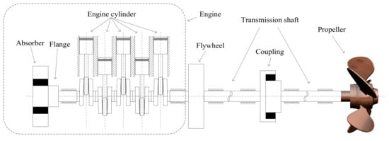
Figure 1.
Schematic diagram of a marine diesel engine propulsion system.
A lumped parameter model is widely used in the calculation of torsional vibration of shafting, which includes three basic components: the homogeneous rigid disk element, the inertia-less damping element, and the inertia-less torsional spring element. In this paper, the ship propulsion shafting system is modeled by 12 polar moments of inertia (J1, J2, J3, J4, J5, J6, J7, J8, J9, J10, J11, J12) and 11 torsional springs (K12, K23, K34, K45, K56, K67, K78,K89, K9,10, K10,11, K11,12) with damping neglected, as shown in Figure 2. The model parameter values (stiffness values and inertial values) are calculated based on a real shafting system of a ship and are given in Table 1, and the natural frequencies of the original system are given in Table 2. Damping is small and thus is neglected.
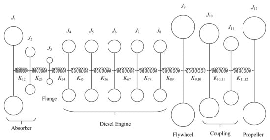
Figure 2.
The lumped parameter model of a marine diesel engine propulsion system.

Table 1.
System parameters.

Table 2.
Frequencies of modes of the original system.
3.2. Desired Modifications under Two Different Operating Conditions
In order to better illustrate that this method can achieve different frequency assignment schemes satisfying complex physical constraints, three cases under two different operating speeds are proposed.
In the first case, it is assumed that the speed of the shafting system is 1500 rpm, so that 25 Hz is the main shafting excitation frequency. It is important to prevent the natural frequencies of the system from coinciding with this excitation frequency and its third harmonic (75 Hz). It is decided to shift the second frequency (24.96 Hz) and the fourth frequency (74.65 Hz) of the original system shown in Table 2 to 30 Hz and 90 Hz, while keeping others unchanged, as shown in the second column of Table 3. Additionally, considering an actual engineering restriction, it is assumed that the inertia and the stiffness of the diesel engine cannot be changed in structural modifications.

Table 3.
Desired system frequencies and physical constraints.
In the second case, the model is about an 888-rpm diesel engine system with a five-blade propeller. In this case, the excitation frequencies include the subharmonics and superharmonics of the rotation speed, and another important excitation frequency is propeller excitation (74 Hz). So, the third and fourth natural frequencies should be respectively modified to become 55 Hz and 80 Hz given in the third column of Table 3, which means that one modified frequency becomes bigger and the other becomes smaller. This case has the same physical constraint as the first case.
Compared with the second case, the third case requires that the third and fourth frequencies be shifted to smaller values (55 Hz and 70 Hz). In addition, the physical constraints are more complex compared with the above two cases. The results are listed in the fourth column of Table 3.
So far, three modification schemes for different trends of frequency changes have been given.
3.3. Results Obtained from the Gradient Flow Method
Based on the method presented in Section 2, the three cases are solved for the partial assignment of the desired natural frequencies of the shafting through modifying the value of the inertias and stiffness at specified locations aiming at meeting the requirements of practical engineering applications. Taking Case One as an example, the computational process of this method is further introduced. Firstly, according to the known inertia and stiffness parameters, Equations (1)–(6) are easy to be solved. Then, is set to a unit matrix, and can be obtained from Equations (7) and (9). It is assumed that the inertia and stiffness parameters (J4, J5, J6, J7, J8 and K45, K56, K67, K78, respectively) of the engine are not changed. In other words, a subset of matrix entry locations L = {(4,5), (5,4), (5,5), (5,6), (6,5), (6,6), (6,7), (7,6), (7,7), (7,8), (8,7)} and their corresponding values = {}. Then, a gradient flow can be defined on the basis of Equations (10)–(14), and the ordinary differential equation can be solved to reconstruct a matrix . Finally, based on Section 2.4, the modified mass and stiffness matrices can be obtained. The detailed results of the three cases obtained from the gradient flow algorithm are presented and analyzed in the next sections.
3.3.1. Case One (Desired Frequencies at 30 Hz and 90 Hz)
After solving the problem, the frequencies of the modified structure and the relative errors between them and the desired values are shown in Table 4, and the comparisons of the inertia values and stiffness values before and after modification are shown in Figure 3 and Figure 4. It can clearly be seen from the results shown in Table 4 that the method is excellent at achieving the desired frequencies for this shafting system: the second and third natural frequencies of the original shaft system are now shifted to 30 Hz and 90 Hz, and they make a perfect match with the desired results, which means that there is no spill-over. Furthermore, for case one, two non-adjacent natural frequencies are modified to show the universality of the method.

Table 4.
Frequencies of modes of the modified system and the relative errors.
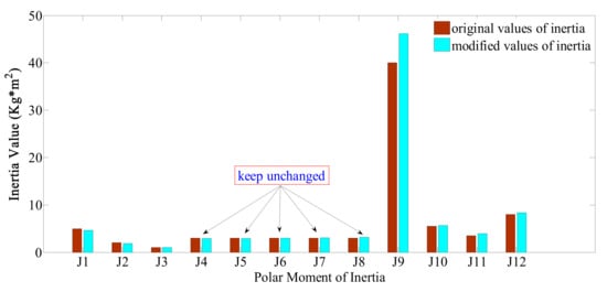
Figure 3.
Comparisons of inertia values before and after modification in Case One where the desired frequencies are at 30 Hz and 90 Hz.
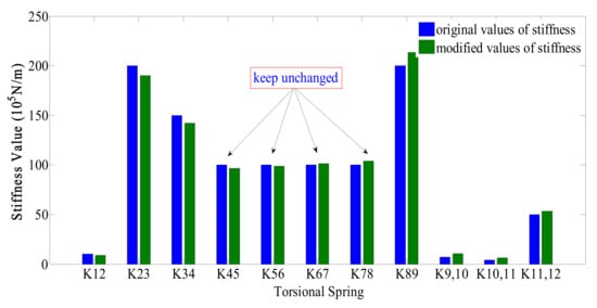
Figure 4.
Comparisons of stiffness values before and after modification in Case One where the desired frequencies are at 30 Hz and 90 Hz.
As shown in Figure 3, the differences between the inertia values before and after modification regarding the inertia of a diesel engine are small and can be considered to be almost identical. Figure 4 indicates that the stiffness parameters for the engine before and after modification are not exactly the same, which are similar to the inertia results; especially, stiffness K45 and stiffness K78 have some errors, but they are very small and acceptable. Therefore, the solution for modification is effective.
3.3.2. Case Two (Desired Frequencies at 55 Hz and 80 Hz)
In this case, the targets are that the third and fourth frequencies need to be changed to 55 Hz and 80 Hz while keeping the other frequencies unchanged. From Table 5, it can be shown that the third and fourth frequencies are successfully shifted to 55 Hz and 80 Hz, respectively. Furthermore, all the relative errors between the modified frequencies and the desired frequencies are equal to 0, except that the error of the 10th natural frequency is 0.11%. This means that all the modified natural frequencies are the same as the expected values.

Table 5.
Frequencies of modes of the modified system and the relative errors.
In Figure 5 and Figure 6, the obtained results of modified inertias and stiffness are shown respectively. The arrows in the figures indicate that the values of the inertias and stiffness are almost the same before and after modification.
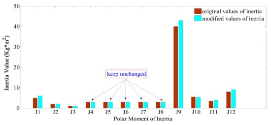
Figure 5.
Comparisons of inertia values before and after modification in Case Two where the desired frequencies are at 55 Hz and 80 Hz.
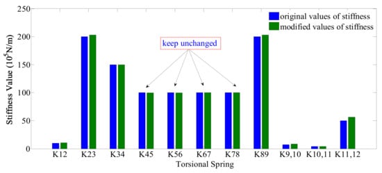
Figure 6.
Comparisons of stiffness values before and after modification in Case Two where the desired frequencies are at 55 Hz and 80 Hz.
3.3.3. Case Three (Desired Frequencies at 55 Hz and 70 Hz)
Compared with the above two cases, the third and fourth frequencies of Case Three are required to become 55 Hz and 70 Hz. As shown in Table 6, the actually achieved values are 55.06 Hz and 70.04 Hz, respectively. Unlike the previous two cases, the physical constraints in the third case become more stringent, which requires the inertias and stiffness of both the engine and the propeller to remain unchanged. Figure 7 shows that the inertias that are not allowed to be modified are indeed kept unchanged. As shown in Figure 8, the stiffness parameters for the engine before and after modification are not exactly the same, which is similar to the inertia parameters; especially, stiffness K45, K56, and K67 have some errors. However, they are very small and acceptable. Therefore, the solution for modification is effective. This case further illustrates the universality of the method.

Table 6.
Frequencies of modes of the modified system and the relative errors.
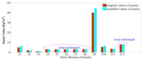
Figure 7.
Comparisons of inertia values before and after modification in Case Three where the desired frequencies are at 55 Hz and 70 Hz.
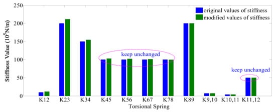
Figure 8.
Comparisons of stiffness values before and after modification in Case Three where the desired frequencies are at 55 Hz and 70 Hz.
Through the above analysis and discussions, it is easy to see that the gradient flow method can achieve a partial assignment of natural frequencies by means of modifying the values of inertias and stiffness at certain locations while keeping the values of inertias and stiffness unchanged at other locations.
4. Torsional Vibration Control and Analysis of a Diesel Generator Set
Symmetric branched structures are widely used in engineering. In the marine engineering field, a symmetrical branched structure is widely used in a gear box system, a dual locomotive parallel system, and a diesel engine system with symmetrical auxiliary equipment. There are two main characteristics regarding the torsional vibration of symmetric branched systems: one is the phenomenon of close natural frequencies, and the other is the phenomenon of synchronous vibration and asynchronous vibration in two symmetric branched shafts. So, the torsional vibration of a branched shafting is more complex than that of a normal straight shafting. In order to better analyze and understand the torsional vibration characteristics of a branched shafting, many scholars [41,42,43,44,45] have studied the analysis methods for the torsional vibration of different branched systems. However, an effective control method for the torsional vibration of branched shafting has rarely been reported. In this section, from the point of view of structural modification, an effective solution is given to the problem of close frequencies of branched structures based on the method introduced in Section 3.
4.1. The Model Setup
In this section, a diesel generator set is taken as the research object, which consists of a vibration absorber, two pumps, gears, engine cylinders, a flywheel, a transmission shaft, a coupling, and a generator, as shown in Figure 9.
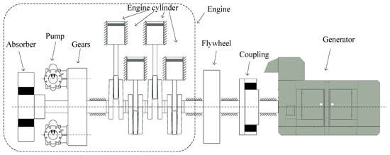
Figure 9.
Schematic diagram of a diesel generator set.
A lumped parameter model for various parts of the shafting is established in Figure 10. It is composed of homogeneous rigid disc elements and massless torsion spring elements, with damping neglected. The model parameter values (stiffness values and inertial values) are calculated based on a real diesel generator set and are given in Table 7, and the natural frequencies of the original system are given in Table 8.
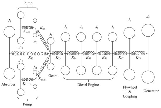
Figure 10.
The lumped parameter model of a diesel generator set.

Table 7.
System parameters.

Table 8.
Frequencies of modes of the original system.
4.2. The Aim of Modification
From Table 8, it is found that the system has close eigenvalues, such as the 10th and 11th natural frequencies. The corresponding modes are given in Figure 11. From Figure 11, it can be concluded that the mode shape corresponding to the 10th natural frequency represents synchronous vibration, while the mode shape corresponding to the 11th natural frequency is asynchronous vibration. It is also clear that the modal amplitudes of inertias J9 and J11 are much larger than those of other inertias when the shafting is vibration in either of these two modes. As a result, once resonance occurs at these two frequencies, the equipment represented by these inertias can undergo large vibration and thus probably serious damage. Therefore, it is necessary to avoid these resonances.
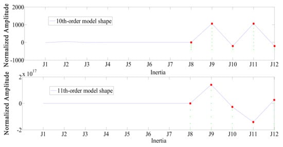
Figure 11.
The mode shapes corresponding to the 10th order and 11th order frequencies.
In this case, it is assumed that the speed of the shafting system is 948 r/m, so that 15.8 Hz is the main shafting excitation frequency. It is important to prevent the excitation frequencies from coinciding with the natural frequencies of the system. So, the 17th harmonic frequency (268.6 Hz) needs to be avoided, and for this purpose, the 10th and 11th natural frequencies of the original system will be moved to 262.5 Hz and 263.0 Hz while keeping the others unchanged, as shown in Figure 12 corresponding to the 10th frequency (267.20 Hz) and the 11th frequency (267.77 Hz) shown in Table 8.
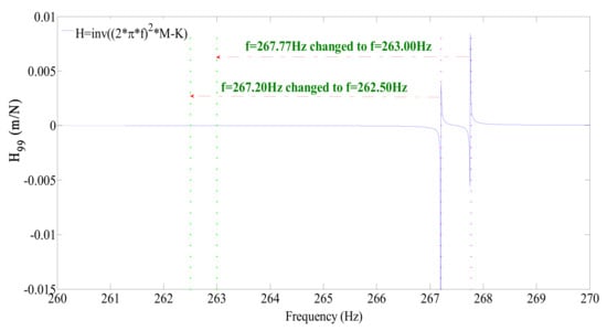
Figure 12.
Frequency response function with desired frequencies modification.
4.3. Results Obtained from the Gradient Flow Method
In this case, it is expected to change the original 10th natural frequency (267.20 Hz) and 11th natural frequency (267.77 Hz) to the corresponding desired frequencies of 262.50 Hz and 263.00 Hz, respectively. From the results given in Table 9, the 10th natural frequency and 11th natural frequency are shifted to 262.50 Hz and 262.99 Hz, respectively, and all the relative errors between the modified frequencies and the desired frequencies are equal to zero. In addition, according to the actual engineering requirements, it is impractical or unrealistic to change the parameters of diesel engines and generators after their designs have been finished or real machines have been produced. For this reason, it is assumed in this example that the relevant inertia (J3, J4, J5, J6, J8) and stiffness (K34, K45, K56, K78) parameters of the diesel engine and generator remain unchanged. From Table 10, it can be shown that the maximum changes of inertia and stiffness are 0.02 (kg∙m2) and 0.04 (105 N/m), respectively. These two small changes have almost no impact on the vibration characteristics; thus, they can be neglected in practice. Through the above analysis, it can be concluded that the torsional vibration of the shafting associated with the close frequencies is effectively controlled by shifting the relevant frequencies under the constraints of practical engineering operability. This example provides a useful scheme for the torsional vibration control of complex branched shafting.

Table 9.
Frequencies of modes of the modified system and the relative errors.

Table 10.
Modified system parameter comparison.
5. Conclusions
With the development of the shipping industry, ship propulsion systems have become more and more complex, which makes the analysis and control of the torsional vibration of shafting systems more difficult. In order to achieve torsional vibration control, suitable structural modifications are an effective solution. However, in practical applications, some modifications of the actual shafting systems are limited by many physical constraints. In this paper, the gradient flow method is applied to determine the required modifications at any location with arbitrary eigenvalues, which are especially useful for structures or equipment that have locations that are not allowed to change, such as those in engineering applications.
In order to demonstrate the effectiveness of this method, two examples of complex ship engine systems are studied, which are a typical ship propulsion shaft system and a diesel generator set. In the first example, the natural frequencies of the original structure are shifted in three different scenarios under two different operating conditions and different physical constraints. In the second example, there are two very close frequencies due to the complex symmetric branches within the system. The partial assignment of these frequencies is achieved for the first time through structural modifications. The success of this method in solving these two examples shows its wide applicability and strength in controlling torsional vibration. It is expected to be applicable to linear passive vibration control for other machines and structures.
Author Contributions
Methodology, M.C. and H.O.; software and analysis, S.L. and D.W.; writing—original draft preparation, M.C.; writing—review and editing, M.C., H.O., and W.L. All authors have read and agreed to the published version of the manuscript.
Funding
This research work is funded by the Fundamental Research Funds for Central Universities (No.3072019CFJ0303) and “National Special Support Program for High-Level Talents”.
Acknowledgments
Most of the research is carried out by the first author during her visit to the Universtiy of Liverpool under the supervision of the second author. Discussions wtih Shike Zhang of University of Liverpool have been helpful.
Conflicts of Interest
The authors declare that there is no conflict of interests regarding the publication of this paper.
Notation
| mass matrix | an orthogonal matrix | ||
| stiffness matrix | all matrices that have the same eigenvalues as | ||
| displacement vector | some matrix entry locations | ||
| acceleration vector | the desired values corresponding to | ||
| a real matrix with the same eigenvalues as the original system | all matrices with the prescribed entries at the desired locations | ||
| a real symmetric matrix with all expected eigenvalues | any given matrix in | ||
| system eigenvalues | the same as , except those at the matrix entry locations that do not belong to are set identically zero | ||
| original system eigenvalues | all locations that do not belong to | ||
| the desired eigenvalues | the projection of any matrix onto the affine subspace | ||
| all the eigenvalues that remain unchanged | a constant matrix in with zero entries at all locations corresponding to and known entries at all other locations | ||
| the mass-normalized eigenvector matrix corresponding to | A function defined to minimize the distance between and | ||
| and | the normalized eigenvector matrices | A function defined the minimization with objective function in terms of | |
| a real symmetric matrix | the gradient of objective function |
References
- Baldwin, J.F.; Hutton, S.G. Natural models of modified structures. AIAA 1985, 23, 1737–1743. [Google Scholar] [CrossRef]
- Chen, S.H.; Yang, X.W.; Lian, H.D. Comparison of several eigenvalue reanalysis methods for modified structures. Struct. Multidiscip. Optim. 2000, 20, 253–259. [Google Scholar] [CrossRef]
- Weissenburger, J.T. Effects of local modification on the vibration characteristics of linear systems. J. Appl. Mech. 1968, 35, 327–332. [Google Scholar] [CrossRef]
- Pomazal, R.J.; Snyder, V.W. Local modifications of damped linear systems. AIAA 1971, 9, 2216–2221. [Google Scholar] [CrossRef]
- Ram, Y.M.; Blech, J.J. The dynamic behaviour of a vibratory system after modification. J. Sound Vib. 1991, 150, 357–370. [Google Scholar] [CrossRef]
- Wang, B.P.; Pilkey, W.D. Eigenvalue reanalysis of locally modified structures using a generalized Rayleigh’s method. AIAA 1986, 24, 938–990. [Google Scholar] [CrossRef]
- To, W.M.; Ewins, D.J. Structural modification analysis using Rayleigh quotient iteration. Int. J. Mech. Sci. 1990, 32, 169–179. [Google Scholar] [CrossRef]
- Mottershead, J.E.; Link, M.; Friswell, M.I. The sensitivity method in finite element model updating: A tutorial. Mech. Syst. Signal Process. 2011, 25, 2275–2296. [Google Scholar] [CrossRef]
- Sestieri, A. Structural dynamic modification. Sadhana. Acad. Proc. Eng. Sci. 2000, 25, 247–260. [Google Scholar]
- Richiedei, D.; Trevisani, A.; Zanardo, G. A constrained convex approach to modal design optimization of vibrating systems. J. Mech. Design 2011, 133, 061011. [Google Scholar] [CrossRef]
- Farahani, K.; Bahai, H. An inverse strategy for relocation of eigenfrequencies in structural design. Part I: First order approximate solutions. J. Sound Vib. 2004, 274, 481–505. [Google Scholar] [CrossRef]
- Farahani, H.; Aryana, F. Design optimisation of structures vibration behaviour using first order approximation and local modification. Comput. Struct. 2002, 80, 1955–1964. [Google Scholar]
- Bucher, I.; Braun, S. The structural modification inverse problem: An exact solution. Mech. Syst. Signal Process. 1993, 7, 217–238. [Google Scholar] [CrossRef]
- Li, T.; He, J.M. Local structural modification using mass and stiffness changes. Eng. Struct. 1999, 21, 1028–1037. [Google Scholar] [CrossRef]
- Park, Y.H.; Park, Y.S. Structural modification based on measured frequency response functions: An exact eigenproperties reallocation. J. Sound Vib. 2000, 237, 411–426. [Google Scholar] [CrossRef]
- Mottershead, J.E. Structural modification for the assignment of zeros using measured receptances. J. Appl. Mech. 2001, 68, 791–798. [Google Scholar] [CrossRef]
- Hu, Y.L.; Michael, Z.Q.; Smith, M.C. Natural frequency assignment for mass-chain system with inerters. Mech. Syst. Signal Process. 2018, 108, 126–139. [Google Scholar] [CrossRef]
- Yuan, Y.X.; Dai, H. An inverse problem for undamped gyroscopic systems. J. Comput. Appl. Math. 2012, 236, 2574–2581. [Google Scholar] [CrossRef][Green Version]
- Tsai, S.H.; Ouyang, H.; Chang, J.Y. Inverse structural modifications of a geared rotor-bearing system for frequency assignment using measured receptances. Mech. Syst. Signal Process. 2018, 110, 59–72. [Google Scholar] [CrossRef]
- Liu, Z.H.; Li, W.Y.; Ouyang, H. Structural modifications for torsional vibration control of shafting systems based on torsional receptances. Shock Vib. 2016. [Google Scholar] [CrossRef]
- Zhang, J.F.; Ye, J.P.; Ouyang, H.; Yin, X. An explicit formula of perturbating stiffness matrix for partial natural frequency assignment using static output feedback. J. Low Freq. Noise Vib. Act. 2018, 37, 1045–1052. [Google Scholar] [CrossRef]
- Singh, K.V.; Ling, X.X. Active control of viscoelastic systems by the method of receptance. J. Vib. Acoust. 2018, 140, 1–6. [Google Scholar] [CrossRef]
- Araujo, J.M.; Carlos, C.E.T.; Goncalves, L.M.G. Robustness of the quadratic partial eigenvalue assignment using spectrum sensitivities for state and derivative feedback designs. J. Low Freq. Noise Vib. Act. 2018, 37, 253–268. [Google Scholar] [CrossRef]
- Ram, Y.M.; Mottershead, J.E.; Tehrani, M.G. Partial pole placement with time delay in structures using the receptance and the system matrices. Linear Algebra Appl. 2011, 434, 1689–1696. [Google Scholar] [CrossRef]
- Wang, X.T.; Zhang, L. Partial eigenvalue assignment with time delay in high order system using the receptance. Linear Algebra Appl. 2017, 523, 335–345. [Google Scholar] [CrossRef]
- Bai, Z.J.; Chen, M.X.; Datta, B.N. Minimum norm partial quadratic eigenvalue assignment with time delay in vibrating structures using the receptance and the system matrices. J. Sound Vib. 2013, 332, 780–794. [Google Scholar] [CrossRef]
- Bai, Z.J.; Yang, J.K.; Datta, B.N. Robust partial quadratic eigenvalue assignment with time delay using the receptance and the system matrices. J. Sound Vib. 2016, 384, 1–14. [Google Scholar] [CrossRef]
- Bai, Z.J.; Lu, M.; Wan, Q.Y. Minimum norm partial quadratic eigenvalue assignment for vibrating structures using receptances and system matrices. Mech. Syst. Signal Process. 2018, 112, 265–279. [Google Scholar] [CrossRef]
- Liu, H.; He, B.X.; Chen, X.P. Minimum norm partial quadratic eigenvalue assignment for vibrating structures using receptance method. Mech. Syst. Signal Process. 2019, 123, 131–142. [Google Scholar] [CrossRef]
- Bai, Z.J.; Chen, M.X.; Yang, J.K. A multi-step hybrid method for multi-input partial quadratic eigenvalue assignment with time delay. Linear Algebra Appl. 2012, 437, 1658–1669. [Google Scholar] [CrossRef]
- Ram, Y.M.; Mottershead, J.E. Multiple-input active vibration control by partial pole placement using the method of receptances. Mech. Syst. Signal Process. 2013, 40, 727–735. [Google Scholar] [CrossRef]
- Zhang, L.; Wang, X.T. Partial eigenvalue assignment of high order systems by multi-input control. Mech. Syst. Signal Process. 2014, 42, 129–136. [Google Scholar] [CrossRef]
- Zhang, L. Multi-input partial eigenvalue assignment for high order control systems with time delay. Mech. Syst. Signal Process. 2016, 72–73, 376–382. [Google Scholar] [CrossRef]
- Zhang, L.; Yu, F.; Wang, X.T. An algorithm of partial eigenstructure assignment for high-order systems. Math. Methods Appl. Sci. 2018, 41, 6070–6079. [Google Scholar] [CrossRef]
- Li, S.; Yu, D.Z. Simulation study of active control of vibro-acoustic response by sound pressure feedback using modal pole assignment strategy. J. Low Freq. Noise Vib. Act. 2016, 35, 167–186. [Google Scholar] [CrossRef]
- Yuan, Y.X. Stiffness matrix modification with vibration test data by displacement feedback technique. J. Vibroeng. 2017, 19, 5149–5160. [Google Scholar] [CrossRef][Green Version]
- Araujo, J.M.; Santos, T. A multiplicative eigenvalues perturbation and its application to natural frequency assignment in undamped second-order systems. Proc. Inst. Mech. Eng. Part I 2018, 232, 963–997. [Google Scholar] [CrossRef]
- Ouyang, H.; Zhang, J.F. Passive modifications for partial assignment of natural frequencies of mass-spring systems. Mech. Syst. Signal Process. 2015, 50–51, 214–226. [Google Scholar] [CrossRef]
- Belotti, R.; Ouyang, H.; Richiedei, D. A new method of passive modifications for partial frequency assignment of general structures. Mech. Syst. Signal Process. 2018, 99, 586–599. [Google Scholar] [CrossRef]
- Chu, M.T.; Diele, F.; Sgura, I. Gradient flow methods for matrix completion with prescribed eigenvalues. Linear Algebra Appl. 2004, 379, 85–112. [Google Scholar] [CrossRef]
- Huang, Y.M.; Hong, C.D. Extended transfer matrix method with complex numbers for branched torsional systems. J. Vib. Control 2001, 7, 155–166. [Google Scholar] [CrossRef]
- Zou, C.P.; Chen, D.S.; Hua, H.X. Torsional vibration analysis of complicated multi-branched shafting systems by modal synthesis method. J. Vib. Acoust. 2003, 125, 317–323. [Google Scholar] [CrossRef]
- Wu, J.S.; Chen, C.H. Torsional vibration analysis of gear-branched systems by finite element method. J. Sound Vib. 2001, 240, 159–182. [Google Scholar] [CrossRef]
- Liu, Z.S.; Chen, S.H.; Xu, T. Derivatives of eigenvalues for torsional vibration of geared shaft systems. J. Vib. Acoust. 1993, 115, 277–279. [Google Scholar]
- Crowther, A.R.; Zhang, N. Torsional finite elements and nonlinear numerical modelling in vehicle powertrain dynamics. J. Sound Vib. 2005, 284, 825–849. [Google Scholar] [CrossRef]
© 2019 by the authors. Licensee MDPI, Basel, Switzerland. This article is an open access article distributed under the terms and conditions of the Creative Commons Attribution (CC BY) license (http://creativecommons.org/licenses/by/4.0/).