An Experimental Investigation on the Progressive Failure of Unsaturated Granular Slopes


Abstract
1. Foreword
2. Materials and Methods
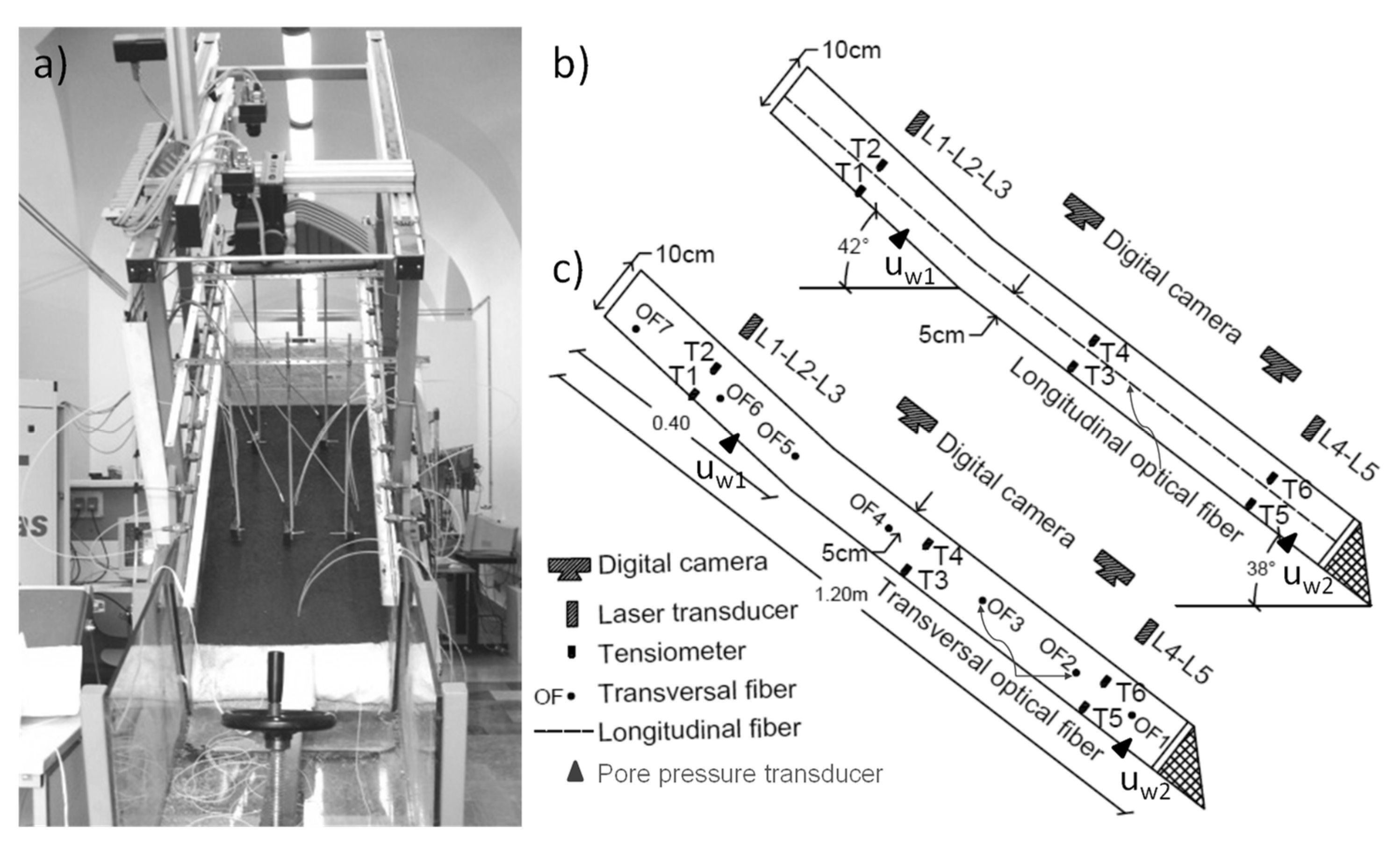
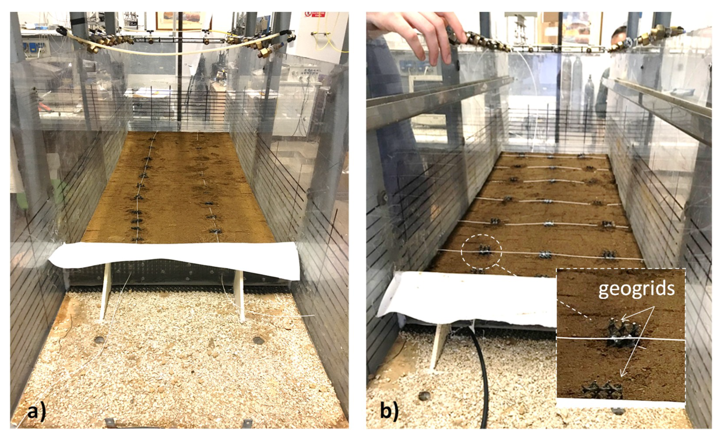
2.1. Equipment
2.2. Technical Characteristics of the Fibers
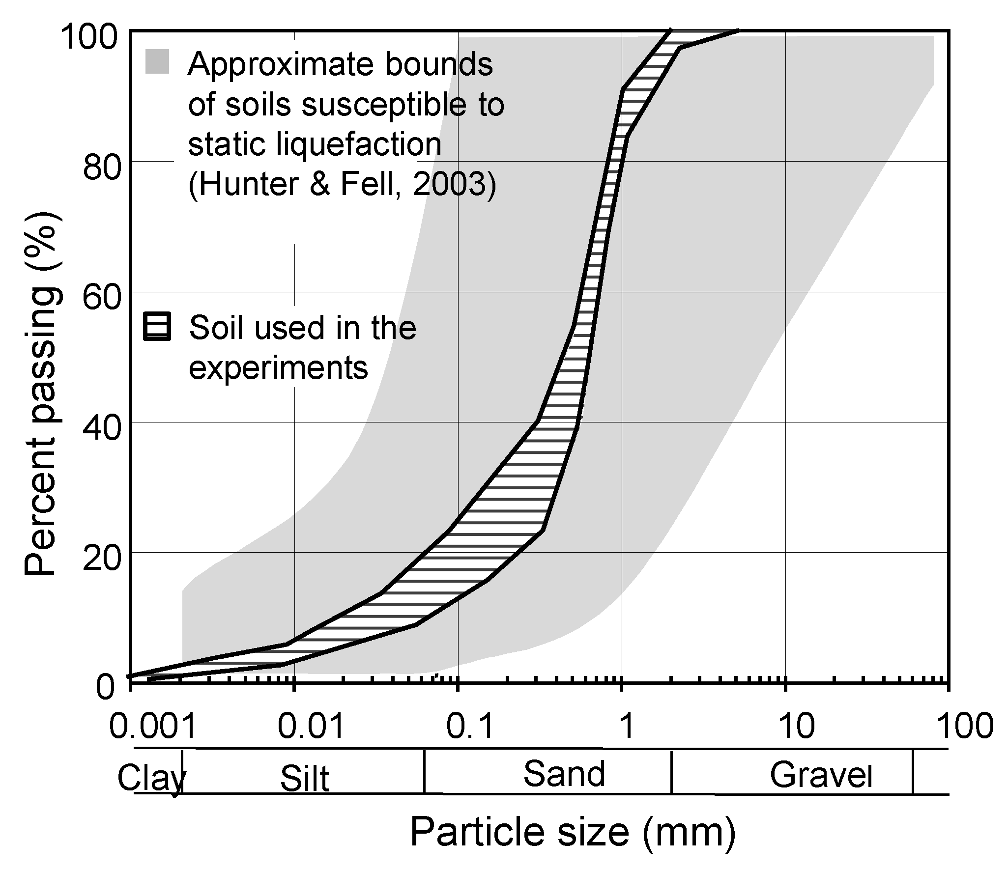
2.3. Soil Properties
3. Experimental Results
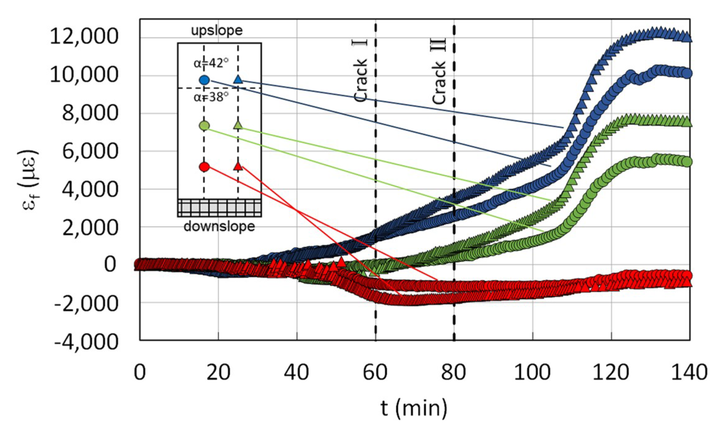
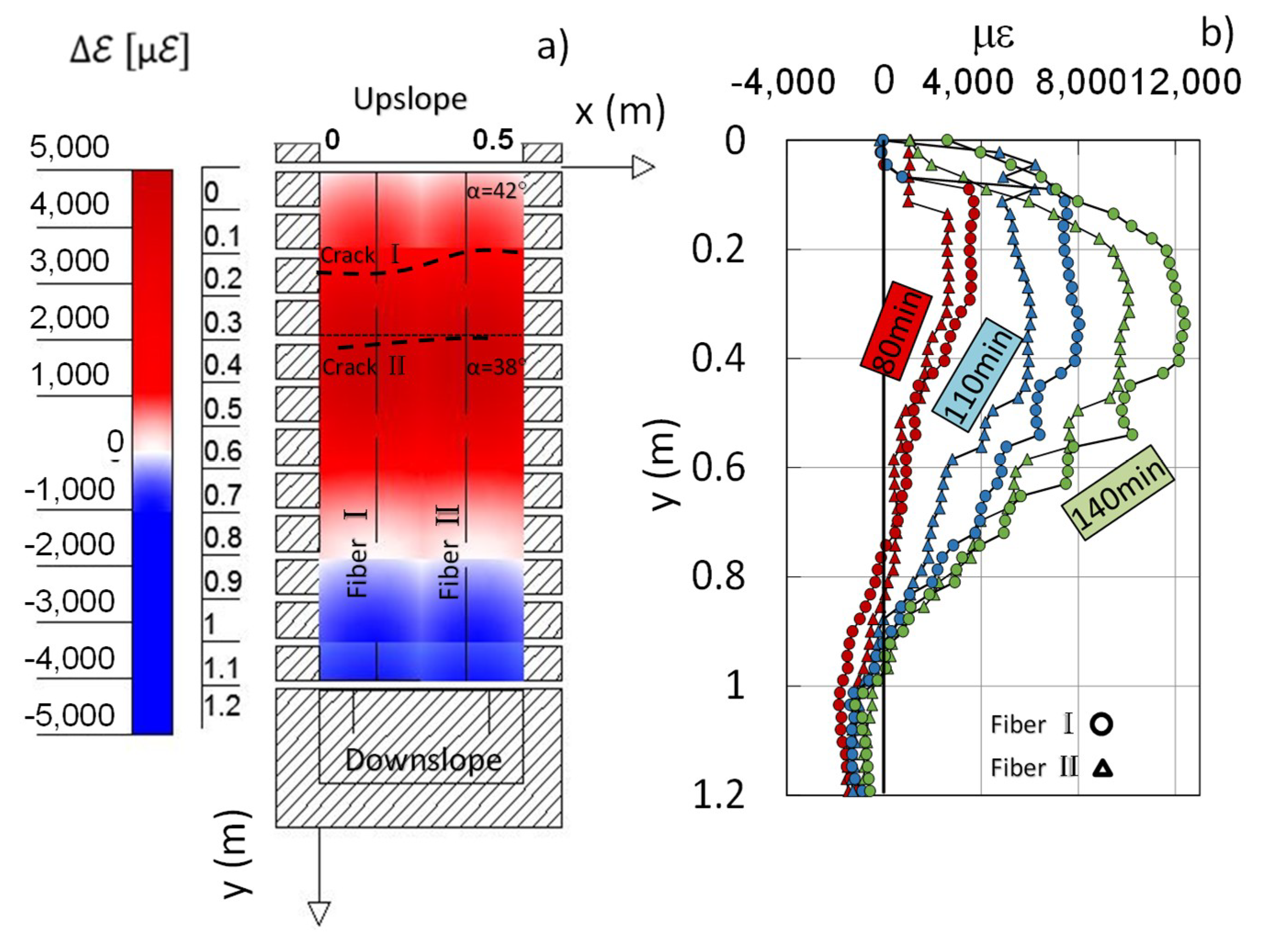
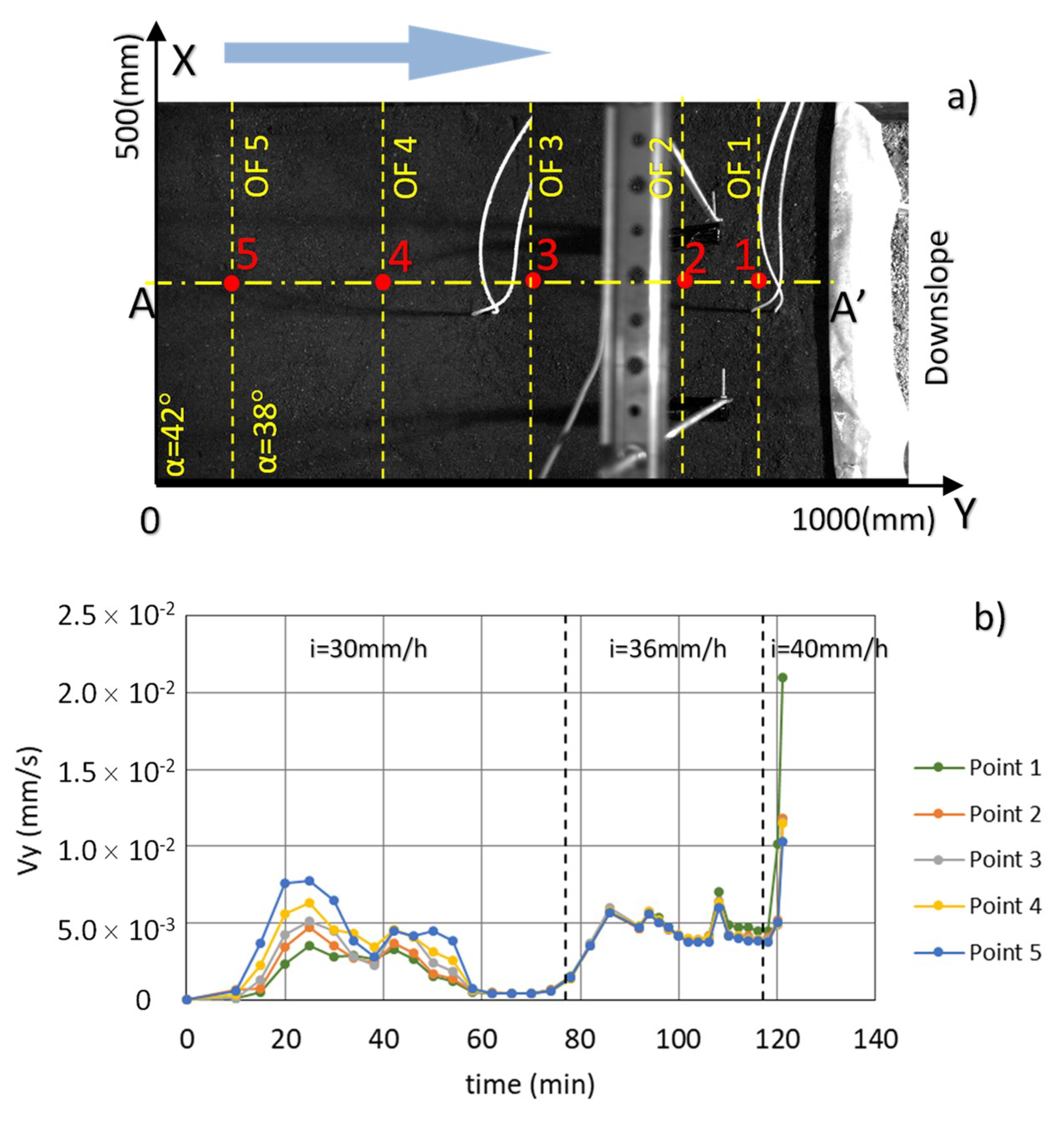
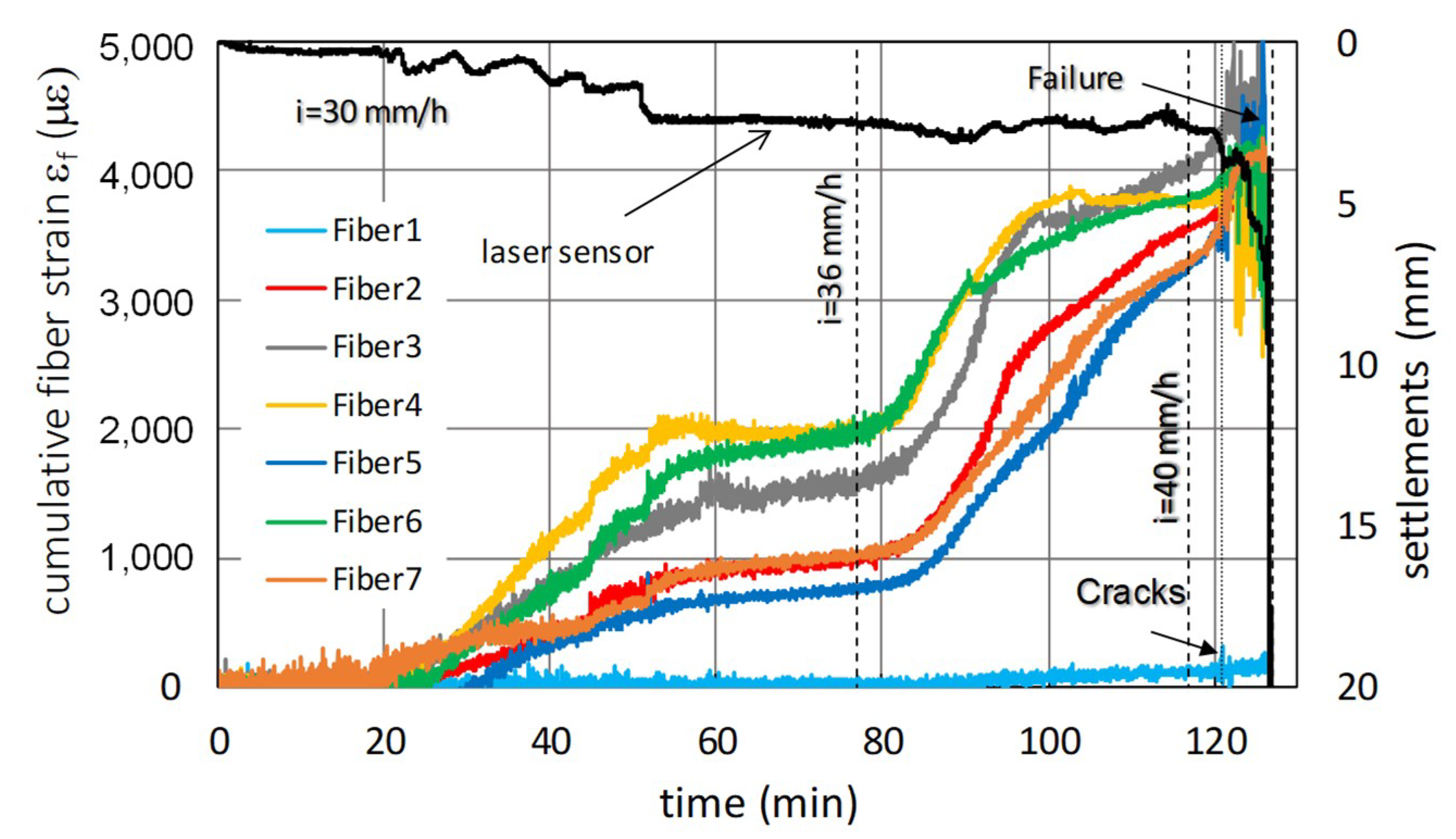
3.1. RP2 Experiment
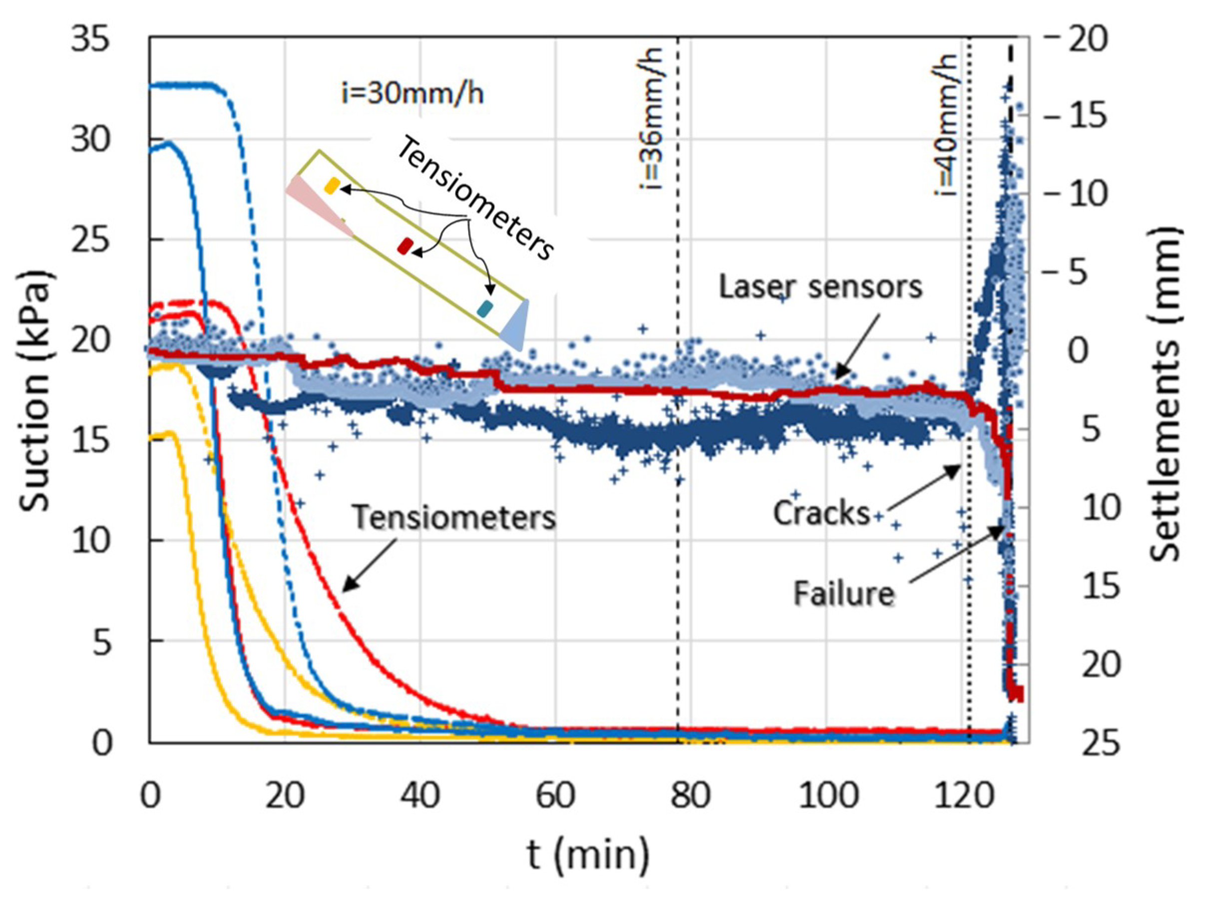
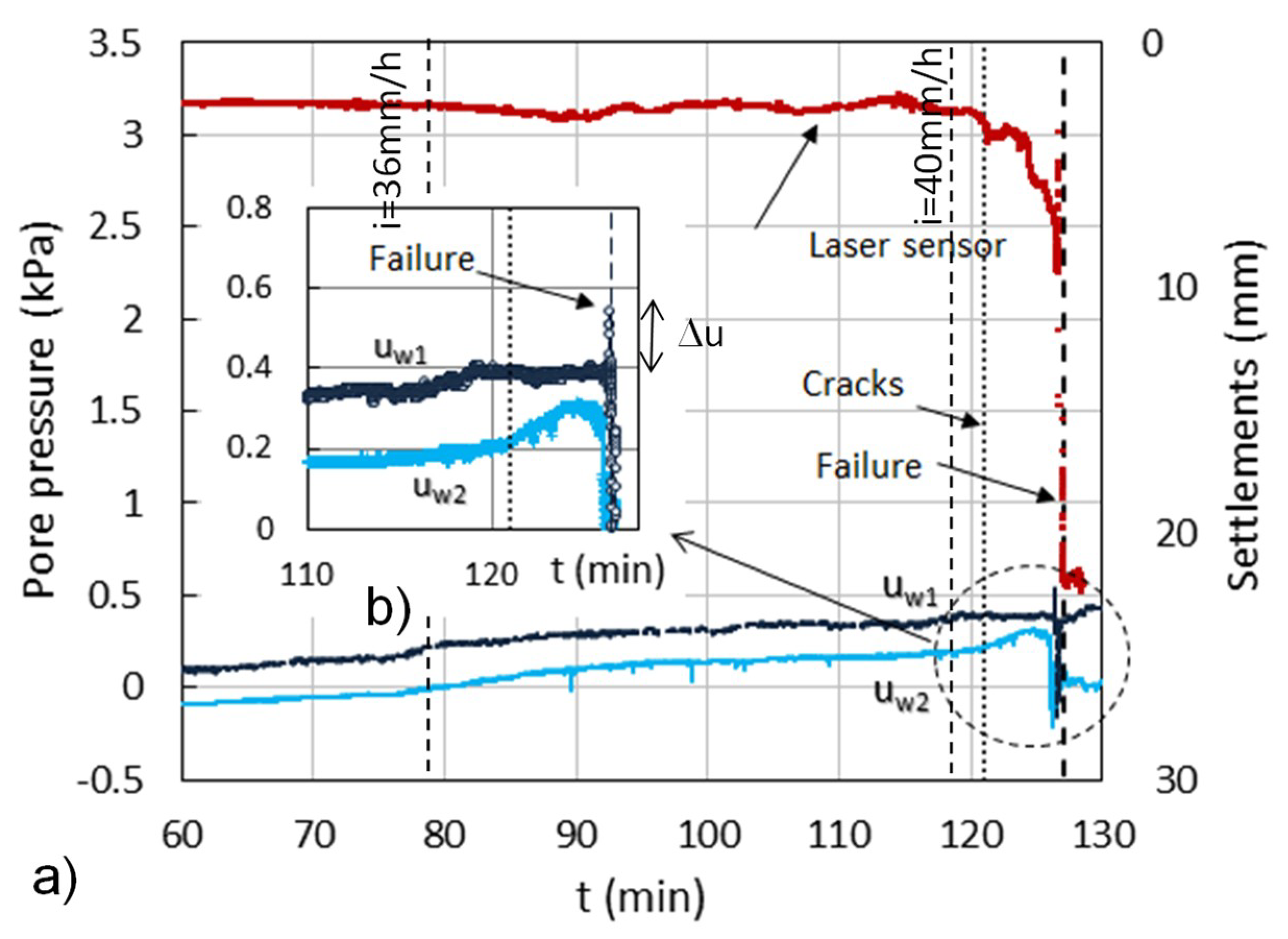
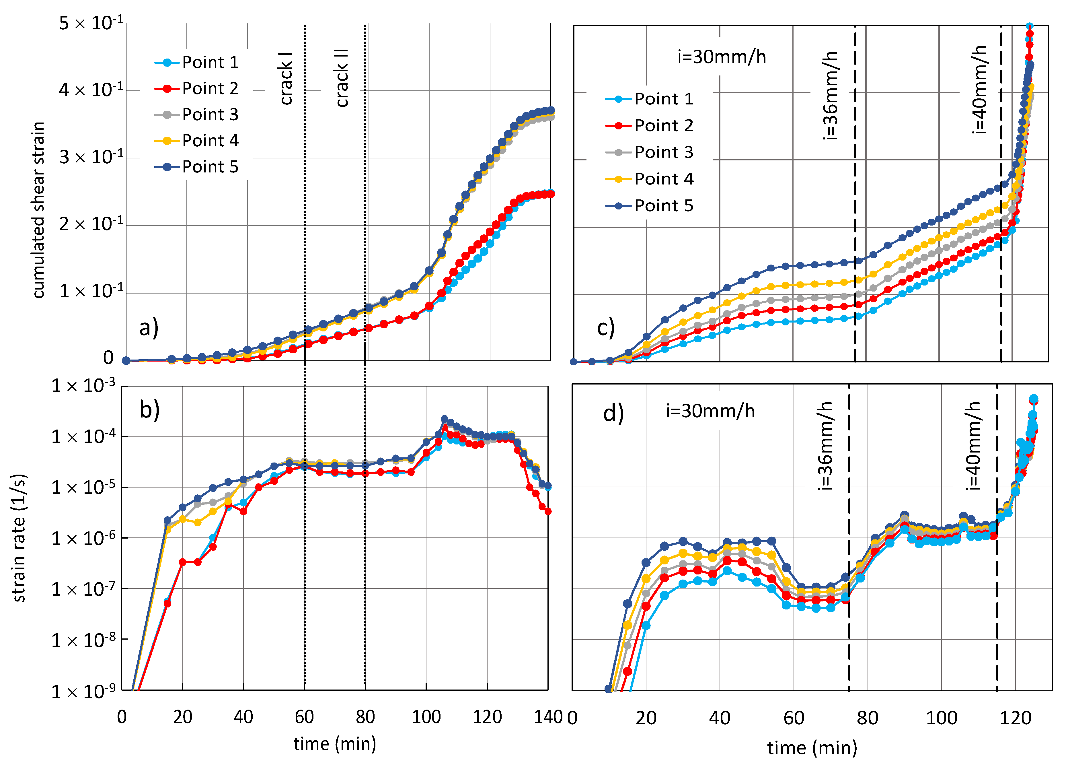
3.2. RP3 Experiment
- -
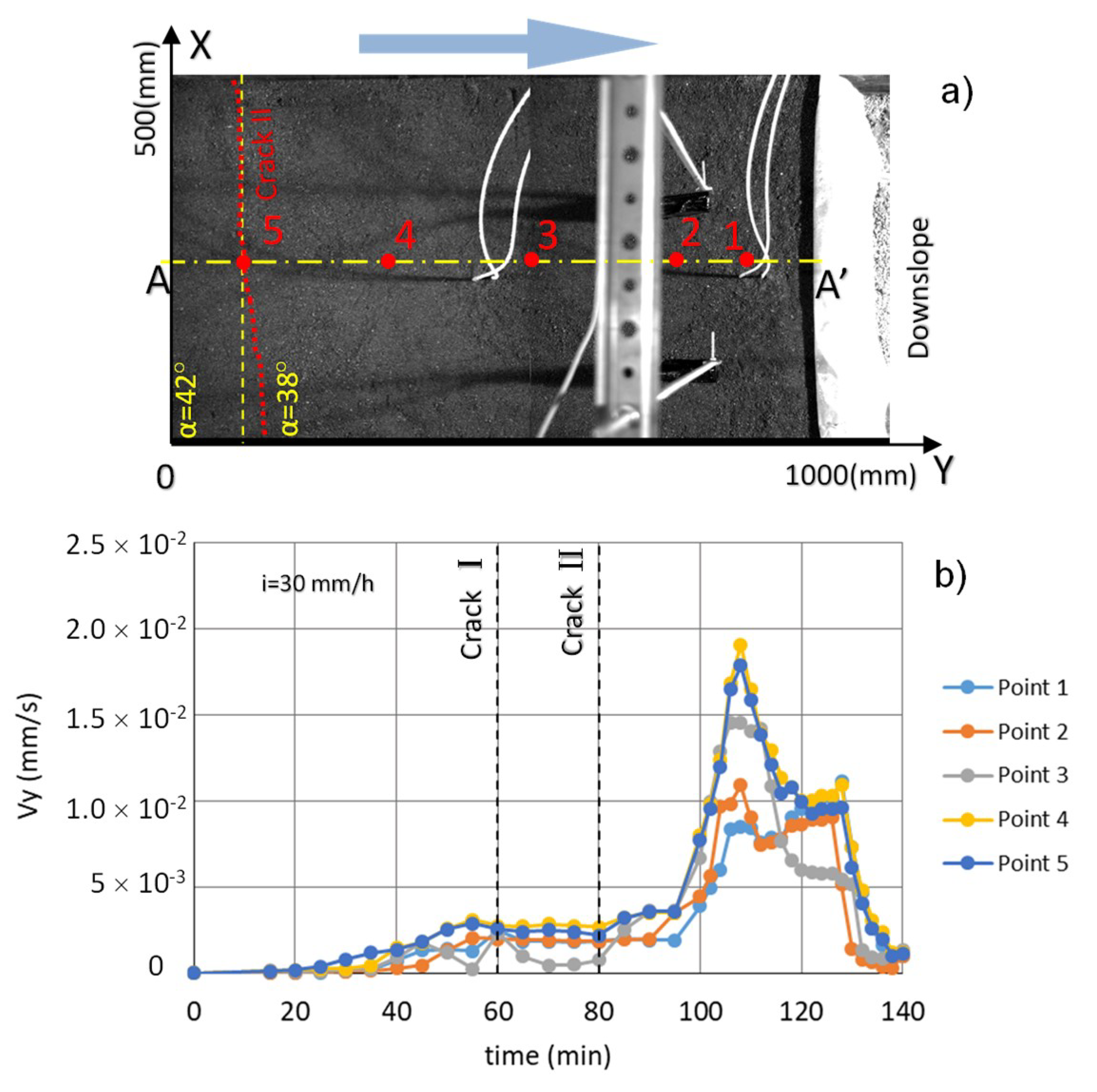
- The progressive downslope movement, with points 4 and 5 moving first and more than the others;
- -
- The shear strain acceleration, which more or less takes place when the rainwater reaches the base of the layer (RP2 experiment, Figure 5);
- -
- The ductile soil behavior, which attains a cumulated shear strain of 3.5 × 10⁻¹ and a strain rate of roughly 10−4 s−1 in the upper zone (RP2 experiment, Figure 13a,b).
4. Conclusions
Author Contributions
Funding
Acknowledgments
Conflicts of Interest
References
- Bjerrum, L. Progressive failure in slopes in overconsolidated plastic clay and shales. ASCE J. Soil Mech. Found. Div. 1967, 93, 139–190. [Google Scholar]
- Leroueil, S.; Locat, A.; Eberhardt, E.; Kovacevic, N. Progressive Failure in Natural and Engineered Slopes. In Proceedings of the 11th International Symposium on Landslides, Banff, AB, Canada, 3–8 June 2012; CRC press: Banff, AB, Canada, 2012; Volume 1, pp. 31–46. [Google Scholar]
- Burland, J.B.; Longworth, T.I.; Moore, J.F.A. A study of ground movement and progressive failure caused by a deep excavation in Oxford clay. Géotechnique 1977, 27, 557–591. [Google Scholar] [CrossRef]
- Cooper, M.R.; Bromhead, E.N.; Petley, D.J.; Grant, D.I. The Selborne cutting stability experiment. Géotechnique 1998, 48, 83–101. [Google Scholar] [CrossRef]
- Alonso, E.E.; Gens, A. Aznalcóllar dam failure. Part 1: Field observations and material properties. Géotechnique 2006, 56, 165–183. [Google Scholar]
- Urciuoli, G.; Picarelli, L.; Leroueil, S. Local soil failure before general slope failure. Geotech. Geol. Eng. 2007, 25, 103–122. [Google Scholar] [CrossRef]
- Yerro, A.; Alonso, E.E.; Pinyol, N.M. Modeling large deformation problems in unsaturated soils. In Proceedings of the 3rd European Conference on Unsaturated Soils, Frontiers on Unsaturated Soils, Paris, France, 12–14 September 2016. [Google Scholar]
- Cascini, L.; Guida, D.; Nocera, N.; Romanzi, G.; Sorbino, G. A Preliminary Model for the Landslides of May 1998 in Campania Region. In Proceedings of the Second International Symposium on Hard Soils–Soft Rocks, Naples, Italy, 12–14 October 1998; Evangelista, A., Picarelli, L., Eds.; Balkema: Naples, Italy, 2000; Volume 3, pp. 1623–1649. [Google Scholar]
- Fiorillo, F.; Guadagno, F.M.; Aquino, S.; De Blasio, S. The December 1999 Cervinara landslides: Further debris flows in the pyroclastic deposits of Campania (southern Italy). Bull. Eng. Geol. Environ. 2001, 60, 171–184. [Google Scholar] [CrossRef]
- Olivares, L.; Damiano, E. Post-failure mechanics of landslides: A laboratory investigation of flowslides in pyroclastic soils. ASCE J. Geotech. Geoenviron. Eng. 2007, 133, 51–62. [Google Scholar] [CrossRef]
- Zhu, Z.-W.; Liu, D.-Y.; Yuan, Q.-Y.; Liu, B.; Liu, J.-C. A novel distributed optic fiber transducer for landslides monitoring. Opt. Lasers Eng. 2011, 49, 1019–1024. [Google Scholar] [CrossRef]
- Schenato, L. A review of distributed fibre optic sensors for geo-hydrological applications. Appl. Sci. 2017, 7, 896. [Google Scholar] [CrossRef]
- Coscetta, A.; Minardo, A.; Olivares, L.; Mirabile, M.; Longo, M.; Damiano, M.; Zeni, L. Wind turbine blade monitoring with brillouin-based Fiber-Optic Sensors. J. Sens. 2017, 9175342. [Google Scholar] [CrossRef]
- Damiano, E.; Mercogliano, P.; Netti, N.; Olivares, L. A “simulation chain” to define a multidisciplinary Decision Support System for landslide risk management in pyroclastic soils. Nat. Hazards Earth Syst. Sci. 2012, 12, 989–1008. [Google Scholar] [CrossRef]
- Intrieri, E.; Gigli, G.; Mugnai, F.; Fanti, R.; Casagli, N. Design and implementation of a landslide early warning system. Eng. Geol. 2012, 147, 124–136. [Google Scholar] [CrossRef]
- Olivares, L.; Damiano, E.; Mercogliano, P.; Picarelli, L.; Netti, N.; Schiano, P.; Savastano, V.; Cotroneo, F.; Manzi, M. A simulation chain for early prediction of rainfall-induced landslides. Landslides 2014, 11, 765–777. [Google Scholar] [CrossRef]
- Olivares, L.; Damiano, E.; Greco, R.; Zeni, L.; Picarelli, L.; Minardo, A.; Guida, A.; Bernini, R. An instrumented flume to investigate the mechanics of rainfall-induced landslides in unsaturated granular soils. Geotech. Test. J. 2009, 32, 108–118. [Google Scholar]
- Damiano, E.; Avolio, B.; Minardo, A.; Olivares, L.; Picarelli, L.; Zeni, L. A laboratory study on the use of optical fibers for early detection of pre-failure slope movements in shallow granular soil deposits. Geotech. Test. J. 2017, 40, 529–541. [Google Scholar] [CrossRef]
- Damiano, E.; Olivares, L.; Picarelli, L. Steep-slope monitoring in unsaturated pyroclastic soils. Eng. Geol. 2012, 137, 1–12. [Google Scholar] [CrossRef]
- Olivares, L.; Picarelli, L. Shallow flowslides triggered by intense rainfalls on natural slopes covered by loose unsaturated pyroclastic soils. Géotechnique 2003, 53, 283–288. [Google Scholar] [CrossRef]
- Hunter, G.; Fell, R. Mechanics of failure of soil slopes leading to “rapid” failure. In Proceedings of the International Conference on Fast Slope Movements: Prediction and Prevention for Risk Mitigation, Napoli, Italy, 11–13 May 2003; pp. 283–290. [Google Scholar]
- Damiano, E.; Greco, R.; Guida, A.; Olivares, L.; Picarelli, L. Investigation on rainfall infiltration into layered shallow covers in pyroclastic soils and its effect on slope stability. Eng. Geol. 2017, 220, 208–218. [Google Scholar] [CrossRef]
- Tatsuoka, F. Compaction Characteristics and Physical Properties of Compacted Soils Controlled by the Degree of Saturation. In Proceedings of the Sixth International Symposium on Deformation Characteristics of Geomaterials. IS-Buenos Aires, Buenos Aires, Argentina, 15–18 November 2015. [Google Scholar]
- Scarcella, G.E.; Giusti, I.; Giusti, S.; Lo Presti, D.C.; Squeglia, N. Strength and Permeability Parameters of Compacted, Partially Saturated Silty and Sandy Soils. Riv. Ital. Geotec. 2018, 2, 58–69. [Google Scholar]
- Damiano, E.; Olivares, L. The role of infiltration processes in steep slopes stability of pyroclastic granular soils: laboratory and numerical investigation. Nat. Hazards 2010, 52, 329–350. [Google Scholar] [CrossRef]
- Picarelli, L.; Evangelista, A.; Rolandi, G.; Paone, A.; Nicotera, M.V.; Olivares, L.; Scotto di Santolo, A.; Lampitiello, S.; Rolandi, M. Mechanical Properties of Pyroclastic Soils in Campania Region. In Proceedings of the 2nd International Workshop on Characterisation and Engineering Properties of Natural Soils, Singapore, 29 November–1 December 2006; Volume 4, pp. 2331–2384. [Google Scholar]
- Olivares, L.; Picarelli, L. Modelling of flowslides behaviour for risk mitigation. In Proceedings of the 6th ICPMG ’06, International Conference on Physical Modelling in Geotechnics, Ng, Hong Kong, China, 2–4 August 2006; Volume 1, pp. 99–113. [Google Scholar]
- Olivares, L. Static liquefaction: An hypothesis for explaining transition from slide to flow in pyroclastic soils. In Proceedings of the Conference TC-11 ISSMGE Transition from Slide to Flow: Mechanisms and Remedial Measure, Trabzon, Turkey, 25–26 August 2001. [Google Scholar]
- Olivares, L.; Damiano, E.; Netti, N.; De Cristofaro, M. Geotechnical Properties of Two Pyroclastic Deposits Involved in Catastrophic Flowslides for Implementation in Early Warning Systems. Geosciences 2019, 9, 24. [Google Scholar] [CrossRef]


| Test. | Slope Length (m) | Slope Width (m) | Slope Thickness (m) | Slope Angle (°) | w (%) | n (%) | Sr (%) | i (mm/h) | Δt (min) |
|---|---|---|---|---|---|---|---|---|---|
| RP2 | 1.2 | 0.50 | 0.10 | 38–42 | 40–43 | 72 | 41–43 | 30 | 158 |
| RP3 | 1.2 | 0.50 | 0.10 | 38–42 | 39–42 | 70 | 44–47 | 30–36–40 | 126 |
© 2019 by the authors. Licensee MDPI, Basel, Switzerland. This article is an open access article distributed under the terms and conditions of the Creative Commons Attribution (CC BY) license (http://creativecommons.org/licenses/by/4.0/).
Share and Cite
Darban, R.; Damiano, E.; Minardo, A.; Olivares, L.; Picarelli, L.; Zeni, L. An Experimental Investigation on the Progressive Failure of Unsaturated Granular Slopes. Geosciences 2019, 9, 63. https://doi.org/10.3390/geosciences9020063
Darban R, Damiano E, Minardo A, Olivares L, Picarelli L, Zeni L. An Experimental Investigation on the Progressive Failure of Unsaturated Granular Slopes. Geosciences. 2019; 9(2):63. https://doi.org/10.3390/geosciences9020063
Chicago/Turabian StyleDarban, Reza, Emilia Damiano, Aldo Minardo, Lucio Olivares, Luciano Picarelli, and Luigi Zeni. 2019. "An Experimental Investigation on the Progressive Failure of Unsaturated Granular Slopes" Geosciences 9, no. 2: 63. https://doi.org/10.3390/geosciences9020063
APA StyleDarban, R., Damiano, E., Minardo, A., Olivares, L., Picarelli, L., & Zeni, L. (2019). An Experimental Investigation on the Progressive Failure of Unsaturated Granular Slopes. Geosciences, 9(2), 63. https://doi.org/10.3390/geosciences9020063