Article

A Method for Correcting Tidal Effect on Shoreline Position Extracted from an Image with Unknown Capture Time

1
Department of Civil Engineering, Tohoku University, Sendai 980-8579, Japan
2
Division of Civil Engineering, Thuyloi University - Southern Campus, 717000 Ho Chi Minh, Vietnam
3
Department of Civil and Environmental Engineering, Tohoku Gakuin University, Tagajo 985-8537, Japan
*
Author to whom correspondence should be addressed.
Geosciences 2017, 7(3), 62; https://doi.org/10.3390/geosciences7030062
Submission received: 24 May 2017 / Revised: 19 July 2017 / Accepted: 21 July 2017 / Published: 24 July 2017

Abstract

:
It is inevitable to find in studies that shoreline position extracted from unknown capture time aerial photograph or satellite image was not corrected to tidal effect. In this study, an approach is introduced that can estimate the capture time of image from the solar azimuth angle and the length of shadow of a vertical object on the horizontal surface on the earth. The capture time of tze aerial photograph estimated from solar azimuth angle has a much smaller deviation than the one estimated from the length of the shadow. This error is acceptable for tidal correction purposes. The approach was also utilized to estimate the capture time of a set of satellite images on Sendai coast. Therefore, the tidal correction was implemented for shoreline positions extracted from those images.

1. Introduction

In the studies of coastal morphology, raw data such as waves, bathymetry, shoreline position, etc., is important and highly required. Among them, shoreline position plays a key role to understand the evolution of morphology in both short-term and long-term periods. Moreover, in the developing countries, where field data of waves, bathymetry, etc., is very limited, shoreline position data plays even more important roles. There are ways to obtain shoreline position such as extracting from aerial photograph or satellite image, video camera monitoring system and GPS data.
Due to the dynamic nature of the idealized shoreline boundary, a shoreline indicator is used as the proxy to represent the “true” shoreline position. Reference [1] summarized two categories of shoreline indicator that have been proposed by various studies. Category 1 includes visually discernible coastal features such as a previous high-tide line or the wet/dry line. The indicator in this category is dependent on the variation of tide from time to time. On the other hand, Category 2 comprises the tidal datum-based shoreline indicator that is obtained from the intersection of coastal profile with a specific vertical, defined by tidal constituents of a particular area, for example, mean high water or mean sea level.
The wet/dry line, which represents the highest extent of the water along the beach during the most recent tidal cycle, is the most commonly used shoreline indicator because it is visible in the field, and can be interpreted on both color and grey scale aerial photographs [2,3]. After delineating, shoreline data needs to be corrected to the tidal level to eliminate the effect of the tide on the position of the shoreline. The amount of tidal correction can be large or small depending on the tidal range and beach slope. The maximum correction amount can be from a few meters to a few dozen meters in cases of mild slope and large tidal range [4,5]. However, in many cases only the dates of capture are available while actual capture times are unknown, especially images collected from open source or captured a long time ago (e.g., Google Earth, Geospatial Information Authority of Japan (GSI - Japan)). Therefore, in many studies shoreline positions were not corrected to tidal level [6,7,8,9]. This could result in large uncertainty of shoreline data and a big challenge for studies in the areas where the amplitude of shoreline change is small.
Usually, aerial photographs and satellite images utilized in the studies of coastal morphology are taken during good weather. They cover a large area on the ground surface including shoreline, and vertical objects such as building, electric pole, etc. Tall objects leave their shadows on the ground surface. There are available literatures which give relationships between the real time and solar azimuth angle (more details in Section 2.1 and Section 2.2), and between real time and the length of shadow of a vertical object on the horizontal surface on the earth (e.g., [10,11,12,13]).
Accordingly, this study would introduce an approach that can correct the tidal effect on the shoreline position extracted from a capture time-unknown image using the solar position and aerial photograph.

2. Methodologies

This study attempts to estimate the capture time of image from solar azimuth angle and the shadow of tall and vertical objects print on rectified image through the solar zenith angle. Once we have obtained the capture time of image, the tidal correction for shoreline position extracted from image can be implemented. The angle between the north direction and the shadow line of a vertical object, and the length of shadow line are measured from rectified image. Solar position (azimuth and zenith angles) of the date that the image was taken is also computed. By comparing the measured angle and length of shadow line with calculated results, the capture time of each image can be obtained.
The earth spins around its pole and orbits the sun. These motions result in days, seasons and years. The daylight time on the earth can be estimated from the solar position. An algorithm for calculating solar position has been proposed in the solar radiation literatures. There are notable attempts such as [9,10,11]. However, these methods are valid in a certain period or have the uncertainty greater than ±0.010. Reference [12] introduced a simple step by step procedure algorithm for calculating solar position. In this study, the algorithm to estimate the solar zenith and azimuth angles, which are important parameters, were derived from several parameters with corrections. They reported that the uncertainty of the solar zenith and azimuth angles calculation is ±0.0003°.

2.1. Method 1—Estimation of Image Capture Time From Solar Azimuth Angle, α s

The solar azimuth angle, α s , is the angle between the north direction and the perpendicular projection of line joining the observer and the sun (Figure 1). It is measured eastward from north and given by Equation (1),
α s   =   Arctan ( sin t cos t sin φ     tan δ cos φ )
where, t is the topocentric local hour angle. Detailed calculation of this parameter is given in Reda and Andreas, 2004 [12]; φ is the observer geographical latitude (in radians), positive or negative if the north or south of the equator; δ is the solar declination angle which is the angle between a line joining the centers of the sun and the earth to the equatorial plane.
Solar declination angle changes every day, in fact, every instant. It is well approximated by the Fourier series, Equation (2),
δ   = n = 0 3 a n cos ( n θ d )   +   b n sin ( n θ d )  
where, dn is the day number, which ranges from 0 on 1 January to 364 on 31 December,
θ d   =   2 π d n 365
a and b are coefficients and given in Table 1. Detailed calculation of the solar declination angle can be found in [10].
From Equation (1), the time-varying of solar azimuth angle in a day-time at a particular place on the earth can be calculated. Therefore, by comparing the value of azimuth angle obtained from the image with the calculated azimuth angle of the same day, the capture time of image can be obtained.

2.2. Method 2—Estimation of Image Captured Time from the Length of Shadow on Horizontal Ground Surface (through Solar Zenith Angle, θ s )

The solar zenith, θ s , is the angle between the local zenith and the line joining observer and sun (Figure 1). It is the complement of solar altitude angle and varying between 0 to π / 2 . The solar zenith angle is given by Equation (4),
θ s   =   π 2     e  
where, e is the solar altitude angle (in radians), given by Equation (5),
e   =   Arcsin ( sin φ sin δ   +   cos φ cos δ cos t )
The length of shadow of a vertical object on horizontal surface, L, can be obtained from Equation (6),
L   =   tan   θ s H
where, H is the height of a vertical object on horizontal ground surface.
From Equation (6), the length of shadow of a vertical object varying in a day-time can be calculated. Therefore, by comparing the value of length of shadow of a vertical object on the image with its calculated length of shadow on the same day, the capture time of image can be obtained.

3. Study Area and Data Collection

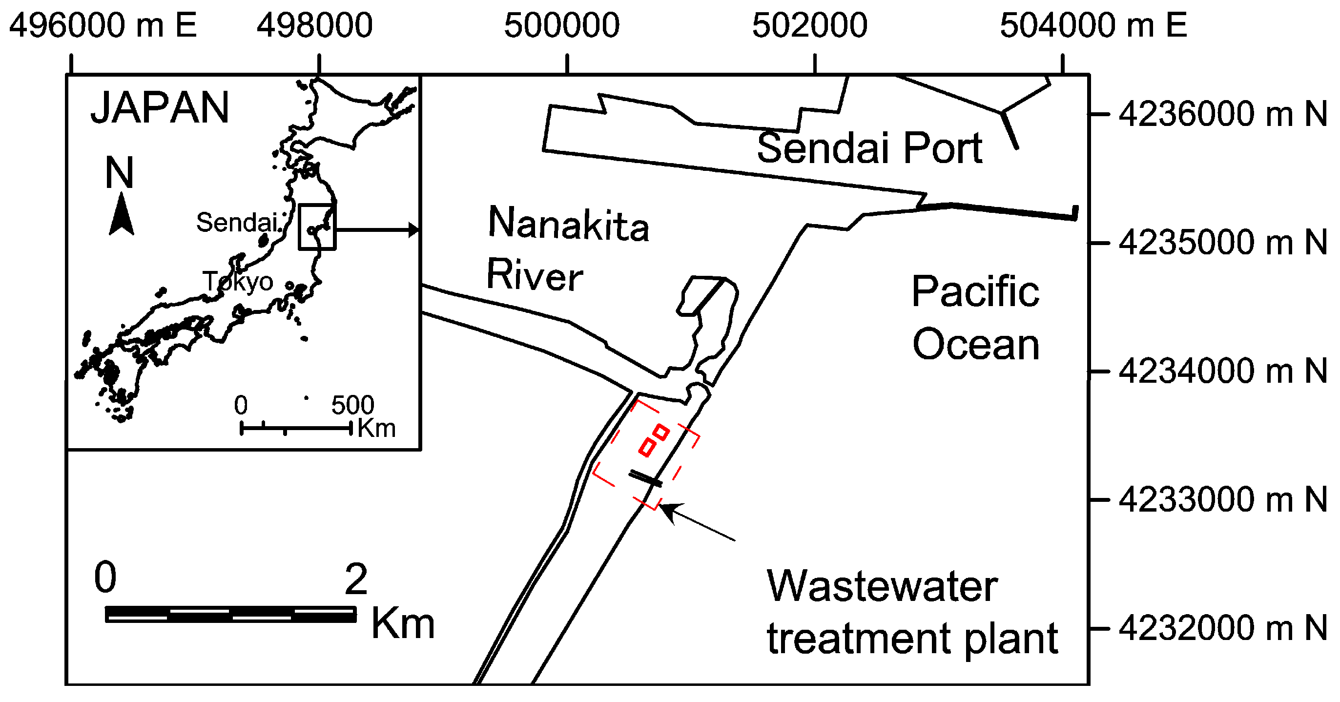
The area around the Nanakita River mouth, which is located in the northern part of Sendai coast, Miyagi Prefecture, Japan (Figure 2), is selected as the study area. Satellite images covering this area, which were downloaded from Google Earth Pro, are available for the period from 2002 until now. There are about 15 clear images, and the objects covered in the image that can be seen visually have been taken in this period. The capture dates of these satellite images are available; however, the capture times are missing.
In order to verify calculated capture time, a set of aerial photographs with the exact capture time of the study area is also utilized. They were taken every one or two months since 1990. The capture date and time of these aerial photographs are available. More information on the aerial photographs and satellite images utilized in this study is presented in Table 2. The photographs cover two buildings of Miniami Gamo wastewater treatment plant. The heights of buildings are ranging from 13.7 m to 20.45 m, respectively, depending on the corners.
Aerial photographs are taken at different times from airplane, hence they need to be rectified. Athough satellite images obtained from Google Earth have been rectified, there is deviation between images that were captured from different epochs. Thus, they are required to be re-rectified too. More details on the rectification process and technique can be found from [14].
Calculated tidal level at Sendai Port is collected from NOWPHAS—Japan’s website and utilized in this study. The mean sea level is T.P. +0.90 m (Tokyo Peil). The tidal range of this area is about 1.6 m with the high and low mean sea levels of 0.00 m and +0.16 m, respectively. The beach slope of 0.11 was reported by [15]. This sole value is utilized for calculating the amount of tidal correction on the shoreline position along the study coast. It can contribute more uncertainty as the beach slope can be different from place to place along the coast. In addition to the survey data, alternatively, the beach slope can also be obtained from empirical formulas (e.g., [16]).
Aerial photographs and satellite images of the study area are georeferenced to the World Geodetic System (WGS-84) using a set of control points which are the fixed points covered in the images. A shore-parallel line with a 210° clockwise north direction is taken as a baseline for shoreline position measurement. Shoreline positions were extracted from rectified images (satellite images) in the alongshore direction based on the difference of color intensity of water and dry sand sides. More details on the technique and uncertainty of image analysis can be found in [1,14,17,18,19].
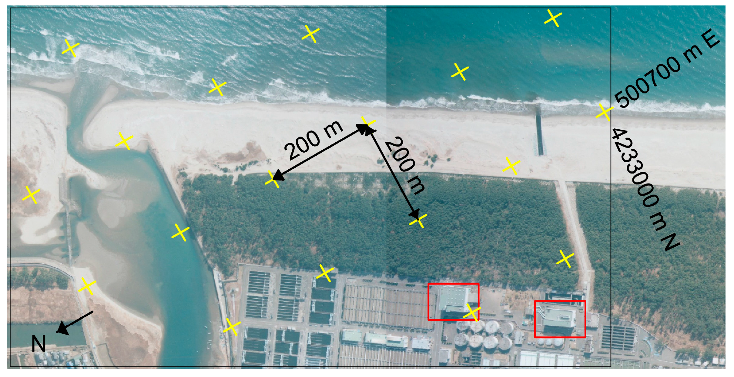
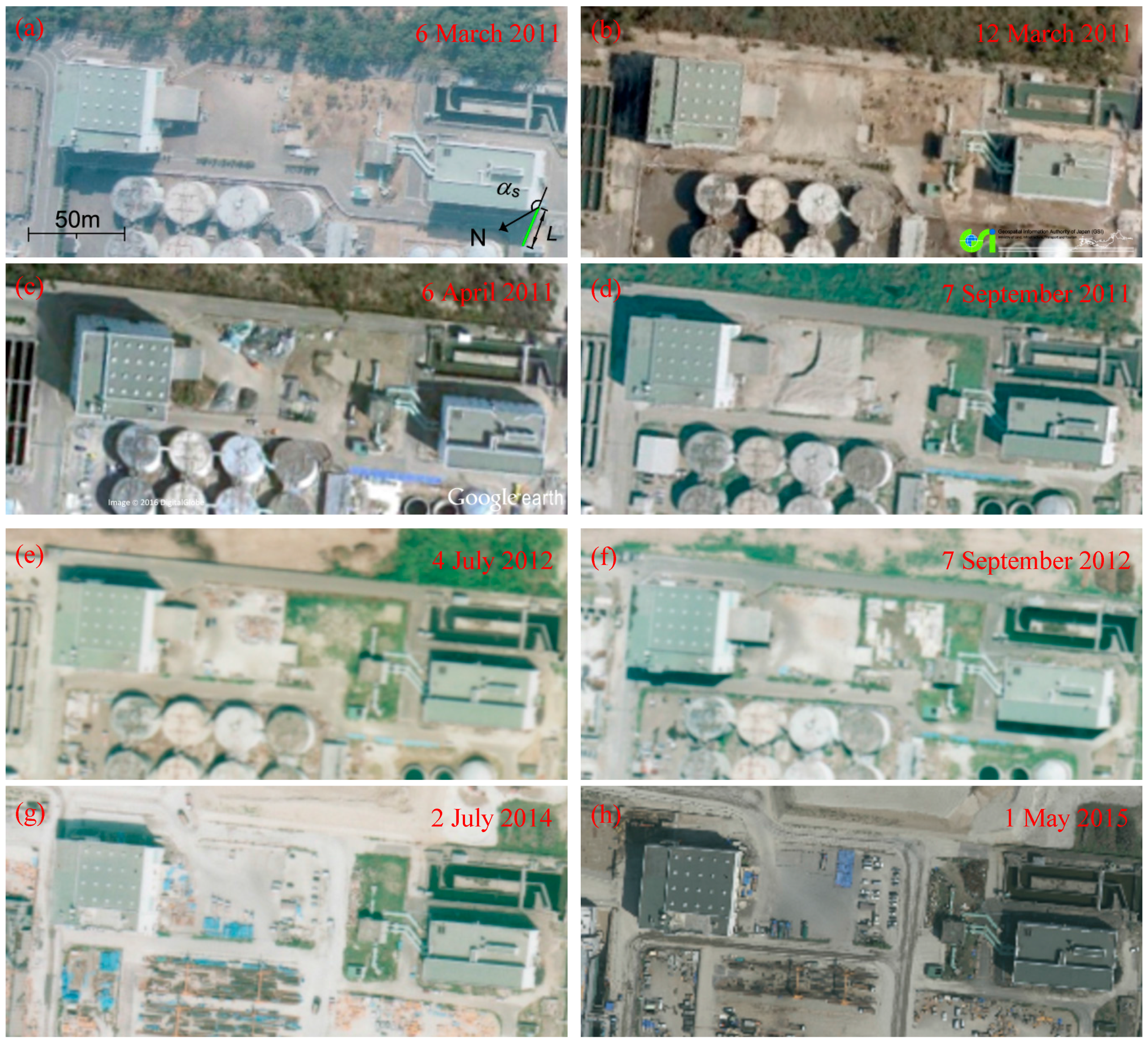
Rectified images are utilized to estimate the solar azimuth angle and the length of shadow of a vertical object on horizontal ground surface. Figure 3 shows a rectified aerial photograph of the study area. In this figure, the locations of buildings are illustrated by rectangles. Figure 4 shows some selected rectified aerial photographs and satellite images, which are used to measure the solar azimuth angle and the length of shadow.

4. Results and Discussion

4.1. Estimation of Capture Time of Aerial Photograph and Satellite Image

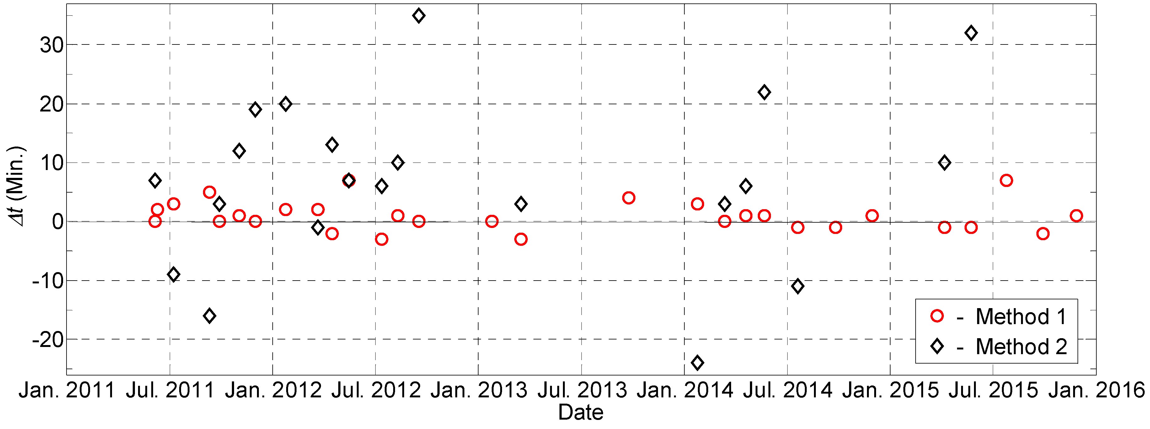
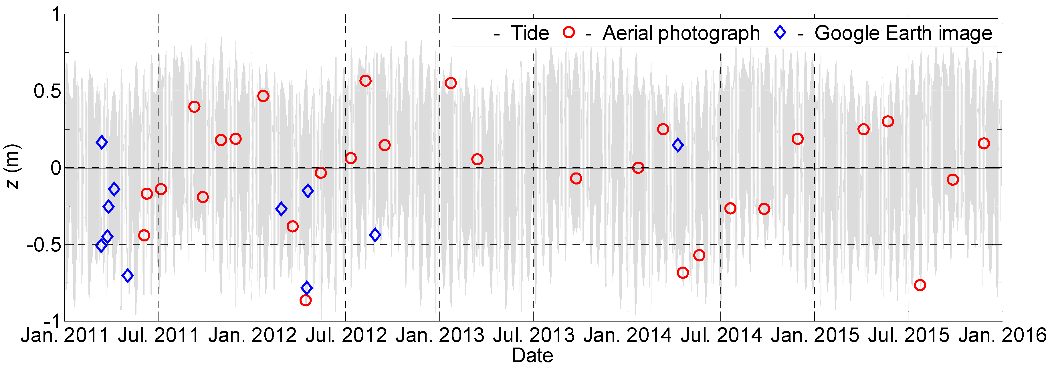
Table 3 illustrates the actual and estimated capture times of images shown in Figure 4. The capture time of an image is the average capture time estimated from the two buildings. In some cases, the capture time can only be estimated from either building because the azimuth angle or length of shadow of one is not clear. The schematic diagram of how to measure the solar azimuth angle and the length of shadow from rectified aerial photograph is given in Figure 4a. The difference between estimated capture time and actual capture time of aerial photographs, Δt, are presented in Figure 5. According to these results, the maximum difference between estimated capture time obtained from solar azimuth angle and actual capture time (Method 1) is 7 min. The error based on the length of shadow (Method 2) is 30 min. This error is much larger compared to the error of Method 1. The large error can be attributed to several reasons such as the non-horizontal ground surface, and the uncertainty in the estimation of the length of shadow on the rectified photographs. For more details, the water level on the T.P. (Tokyo Peil) datum at the time of images captured is given in Figure 6. According to these results, many images were captured at very low or high tide. That can cause large uncertainty if the tidal correction is not implemented. In order to know more details about the maximum amount of tidal level change associated to the error of capture time estimation, a function, Equation (7), which describes the motion of a tide, is utilized. This is the simplified form of the theoretical form of local astronomical tide given by Equation (8).
y   =   a sin σ t
  y =   a n c o s ( σ t     φ n )
where, a is the tidal amplitude; σ is the tidal angular frequency; ϕ is the phase difference. Based on Equation (7), the relationship between tidal level variation, Δy, associated with the change of time, Δt, can be given as Equation (9),
Δ y   =   a σ cos σ t   Δ t
For example, a semidiurnal tide with the tidal range of 1.5 m (a = 0.75 m), the maximum error of tidal level estimation associated with the error of capture time estimation, Δt = 7 min, presented above is Δymax = 5 cm. Therefore, the error of tidal level estimation can be neglected.
From the above results and discussion, it can be said that the capture time of image estimated from solar azimuth angle is more accurate than the one estimated from the length of shadow. Moreover, that error is small and acceptable for the purpose of tidal correction of shoreline position.

4.2. Tidal Correction for Satellite Image

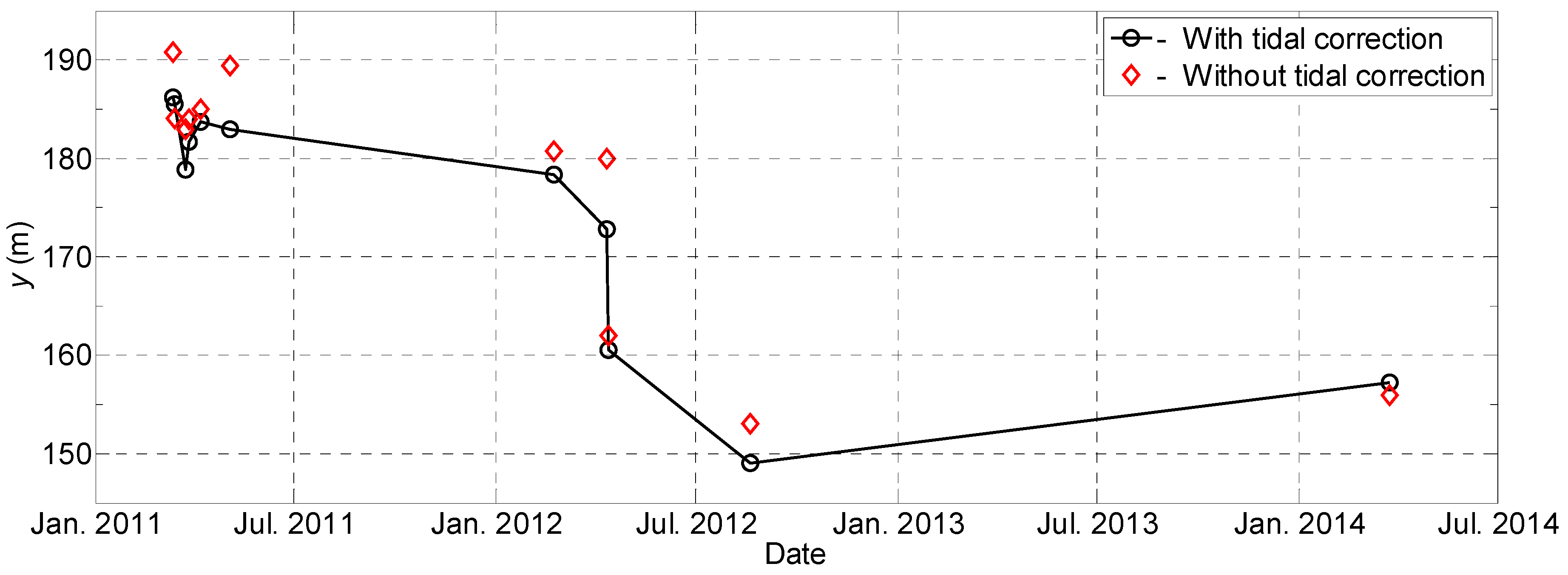
Satellite image from Google Earth Pro, aerial photograph from GSI Japan or images from open sources, for which the actual capture time is not available, can be estimated based on the methods from the latter parts. In this study, satellite images collected from Google Earth Pro are utilized. The time of capture is estimated based on the solar azimuth angle available on the image. After obtaining the estimated capture time for each image, the tidal correction for shoreline position extracted from the image is also implemented. The amount of tidal correction is the multiple of the difference between water level at the moment of capture and mean sea level with the beach slope of 0.11. Figure 7 presents the temporal variation of shoreline positions extracted from satellite images from cases without and with tidal correction. The maximum tidal correction is 9.1 m. In addition to the uncertainty contributed from other sources such as image rectification, shoreline detection, etc., the above amount of tidal correction could significantly affect the investigation of shoreline evolution if the correction is not implemented.

5. Conclusions

This study has introduced an approach to extract the tidal correction for shoreline position from images whose capture times are missing. This method is highly useful for the images collected from Google Earth, GSI Japan or other open sources. The capture time of the image can be estimated from the solar azimuth angle and the length of shadow of a vertical object on the horizontal ground surface. The capture time estimated from the solar azimuth angle is more accurate than the other one. The difference between the estimate and actual capture time is small and acceptable for tidal correction purposes.

Acknowledgments

This work was supported by JSPS KAKENHI. Authors would like to express their gratitude to the above support.

Author Contributions

There three co-authors, Vo Cong Hoang Hitoshi Tanaka and Yuta Mitobe, contribute to this article. Author analyzes the data, joins group discussion and writes the paper. Author leads group discussion, checks the contents and supports publishing. Author writes Matlab codes for satellite images analysis and joins group discussion.

Conflicts of Interest

The authors declare no conflict of interest.

References

  1. Boak, E.H.; Turner, I.L. Shoreline definition and detection: A review. J. Coast. Res. 2005, 21, 688–703. [Google Scholar] [CrossRef]
  2. Crowell, M.; Leatherman, S.P.; Buckley, M.K. Historical shoreline change: Error analysis and mapping accuracy. J. Coast. Res. 1991, 7, 839–852. [Google Scholar]
  3. Leatherman, S.P. Shoreline change mapping and management along the U.S. east coast. J. Coast. Res. 2003, 38, 5–13. [Google Scholar]
  4. Chen, W.W.; Chang, H.K. Estimation of shoreline position and change from satellite images considering tidal variation. Estuar. Coast. Shelf Sci. 2009, 84, 54–60. [Google Scholar] [CrossRef]
  5. Hoang, V.C.; Tanaka, H.; Mitobe, Y. Analysis of shoreline behavior on Sendai coast before and after the 2011 tsunami. Coast. Eng. Proc. 2014. Available online: https://journals.tdl.org/icce/index.php/icce/article/view/7887 (accessed on 24 May 2017).
  6. Muslim, A.M.; Ismail, K.I.; Khalil, I.; Razman, N.; Zain, K. Detection of shoreline changes at Kuala Terengganu, Malaysia from multi-temporal satellite sensor imagery. In Proceedings of the 34th International Symposium on Remote Sensing of Environment, Sydney, Australia, 10–15 April 2011. [Google Scholar]
  7. Adityawan, M.B.; Tanaka, H. Shoreline changes at Sendai Port due to the Great North East Japan, Tsunami of 2011. In Proceedings of the 7th International Conference on Coastal Dynamics, Arcachon, France, 24–28 June 2013; pp. 63–72. [Google Scholar]
  8. Hoang, V.C.; Thanh, T.M.; Viet, N.T.; Tanaka, H. Shoreline change at the Da Rang River Mouth, Vietnam. In Proceedings of the 5th International Conference on Estuaries and Coasts, Muscat, Oman, 2–4 November 2015; pp. 312–318. [Google Scholar]
  9. Noshi, Y.; Uda, T.; Kobayashi, A.; Miyahara, S. Beach changes observed in Phan Rang City in southeast Vietnam. In Proceedings of the 8th International Conference on Asian and Pacific coasts, Chennai, India, 7–10 September 2015; pp. 163–170. [Google Scholar]
  10. Iqbal, M. An Introduction to Solar Radiation, 1st ed.; Academic Press: New York, NY, USA, 1983; 390p, ISBN 9780123737526. [Google Scholar]
  11. Hartmann, L.D. Global Physical Climatology; Academic Press: New York, NY, USA, 1994; 411p, ISBN 9780080571638. [Google Scholar]
  12. Nagasawa, K. Computations of Sunrise and Sunset; Chijinshokan: Tokyo, Japan, 1999; 160p, ISBN 978-4805206348. (In Japanese) [Google Scholar]
  13. Reda, I.; Andreas, A. Solar position algorithm for solar radiation applications. Sol. Energy 2004, 76, 577–589. [Google Scholar] [CrossRef]
  14. Moore, L.J. Shoreline mapping techniques. J. Coast. Res. 2000, 16, 111–124. [Google Scholar]
  15. Kurosawa, T.; Tanaka, H. A study of detection of shoreline position with aerial photographs. J. JSCE Ser. B2 2001, 48, 586–590. (In Japanese) [Google Scholar] [CrossRef]
  16. Sunamura, T. Quantitative predictions of beach-face slopes. Geol. Soc. Am. Bull. 1984, 95, 242–245. [Google Scholar] [CrossRef]
  17. Virdis, S.G.P.; Oggiano, G.; Disperati, L. A geomatics approach to multitemporal shoreline analysis in Western Mediterranean: the case of Platamona-Maritza beach (northwest Sardinia, Italy). J. Coast. Res. 2012, 28, 624–640. [Google Scholar] [CrossRef]
  18. Fletcher, C.; Rooney, J.; Barbee, M.; Lim, S.C.; Richmond, B. Mapping shoreline change using digital orthophotogrammetry on Maui, Hawaii. J. Coast. Res. 2003, 38, 106–124. [Google Scholar]
  19. Cenci, L.; Disperati, L.; Sousa, L.P.; Phillips, M.; Alve, F.L. Geomatics for Integrated Coastal Zone Management: Multitemporal shoreline analysis and future regional perspective for the Portuguese Central Region. J. Coast. Res. 2013, 65, 1349–1354. [Google Scholar] [CrossRef]
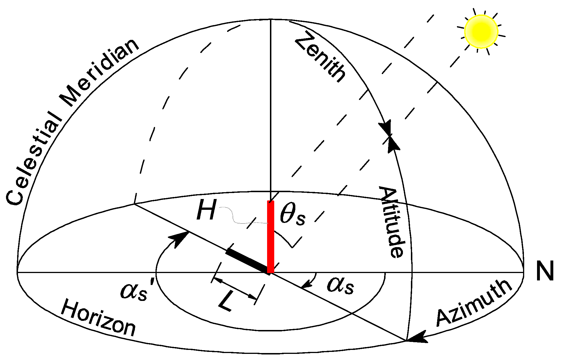
Figure 1. Spherical geometry for solar azimuth and zenith angles calculation.
Geosciences 07 00062 g001
Figure 2. Location map of study area.
Geosciences 07 00062 g002
Figure 3. Rectified aerial photograph of the study area (taken on 6 March 2011).
Geosciences 07 00062 g003
Figure 4. Measuring azimuth angle and length of shadow on aerial photographs and satellite images, (ah) are the selected rectified images.
Geosciences 07 00062 g004
Figure 5. Error of estimated capture time of aerial photograph (∆t = estimated capture time—actual capture time).
Geosciences 07 00062 g005
Figure 6. Estimated capture time of image and calculated tidal level at Sendai Port (T.P., Tokyo Peil).
Geosciences 07 00062 g006
Figure 7. Temporal variation of extracted shoreline position in cases without and with tidal correction.
Geosciences 07 00062 g007
Table 1. Values of coefficient a and b.
nanbn
00.006918
1−0.3999120.070257
2−0.0067580.000907
3−0.0026970.001480
Table 2. Summary characteristics of aerial photograph and satellite image.
No.DateTaking TimeSourceScaleSpatial Resolution (m)
16 March 20119:53Aerial photograph1:80000.5
212 March 2011NAGoogle Earth ProNANA
314 March 2011NAGoogle Earth ProNANA
424 March 2011NAGoogle Earth ProNANA
527 March 2011NAGoogle Earth ProNANA
66 April 2011NAGoogle Earth ProNANA
73 May 2011NAGoogle Earth ProNANA
88 June 201111:27Aerial photograph1:80000.5
96 July 201110:29Aerial photograph1:80000.5
107 September 201114:25Aerial photograph1:80000.5
1124 September 20119:18Aerial photograph1:80000.5
1229 October 20119:33Aerial photograph1:80000.5
1326 November 20119:17Aerial photograph1:80000.5
1418 January 201210:30Aerial photograph1:80000.5
1522 February 2012NAGoogle Earth ProNANA
1614 March 201211:36Aerial photograph1:80000.5
178 April 20129:59Aerial photograph1:80000.5
1810 April 2012NAGoogle Earth ProNANA
1912 April 2012NAGoogle Earth ProNANA
207 May 201214:28Aerial photograph1:80000.5
214 July 201214:10Aerial photograph1:80000.5
221 August 201215:46Aerial photograph1:80000.5
2319 August 2012NAGoogle Earth ProNANA
247 September 201211:20Aerial photograph1:80000.5
2512 January 201313:31Aerial photograph1:80000.5
264 March 201310:5Aerial photograph1:80000.5
279 September 201312:39Aerial photograph1:80000.5
287 January 201411:48Aerial photograph1:80000.5
2924 February201411:6Aerial photograph1:80000.5
3024 March 2014NAGoogle Earth ProNANA
312 April 201410:8Aerial photograph1:80000.5
324 May 201411:30Aerial photograph1:80000.5
332 July 201414:22Aerial photograph1:80000.5
346 September 20149:24Aerial photograph1:80000.5
358 November 201411:38Aerial photograph1:80000.5
3615 March 201510:19Aerial photograph1:80000.5
371 May 201514:0Aerial photograph1:80000.5
382 July 20159:56Aerial photograph1:80000.5
393 September 201512:58Aerial photograph1:80000.5
401 November 201511:52Aerial photograph1:80000.5
Table 3. Actual capture times and estimated capture times of images.
Image (Figure)Capture Time
(UTC+9.00) Osaka, Sapporo, Tokyo
ActualEstimated (Unit: Minute)Remark
Method 1Method 2
Figure 4a9:539:5310:00 (+7)Aerial photograph
Figure 4bNA 13:50NASatellite image from Google Earth Pro
Figure 4cNA 14:32NAAerial photograph from GSI-Japan
Figure 4d14:2514:30 (+5)14:15 (−10)Aerial photograph
Figure 4e14:1014:07 (−3)14:11 (+1)Aerial photograph
Figure 4f11:2011:2011:55 (+35)Aerial photograph
Figure 4g14:2214:21 (−1)14:11 (−11)Aerial photograph
Figure 4h14:0013:59 (−1)14:23 (+23)Aerial photograph