Article

Identification and Application of Preferred Seepage Channels in Turbidite Lobe Reservoirs of Formation A in Z Oilfield

Sinopec International Petroleum Exploration and Development Corporation, Beijing 100029, China
Geosciences 2025, 15(9), 328; https://doi.org/10.3390/geosciences15090328
Submission received: 22 July 2025 / Revised: 19 August 2025 / Accepted: 21 August 2025 / Published: 23 August 2025

Abstract

Turbidite lobe reservoirs represent critical deep-sea hydrocarbon targets, yet preferred seepage channels within them remain poorly characterized. This paper establishes a method for identifying internal preferred seepage channels in turbidite lobe reservoirs using data including seismic, core, thin section, logging, and production performance, combined with neural network technology. A neural network model for predicting reservoir productivity types can be obtained by taking the average logging data of reservoir intervals as input and the reservoir productivity types categorized by meter oil production index calculated by actual production data as the target. By applying the trained neural network model and inputting actual logging attribute model, the reservoir productivity types of single wells are obtained. Using the attribute model of natural gamma ray, acoustic, neutron, density, deep lateral, and shallow lateral logs, which are built by using the actual logging data and Sequential Gaussian Simulation, and supervising with the single well reservoir productivity type, the reservoir productivity type at any position in the reservoir can be predicted. It predicts their spatial distribution characteristics, reveals the genetic mechanism of preferred seepage channels, and discusses the significance of identifying preferred seepage channels for oilfield development. The results show that the reservoir productivity types in the study area can be divided into five categories with progressive improvement in productivity (A, B, C, D, and E) according to the increase in oil production index per meter, among which Type E reservoirs represent typical preferred seepage channels. The attribute model of reservoir productivity types indicates that, horizontally, types E and B are locally developed in the study area, while types D, C, and A are widely distributed. The preferred seepage channels can be divided into two types according to the shape: zonal (length to width > 2:1) and sheet-like (length to width ≤ 2:1). Vertically, types C, D, and E are relatively well-developed in layers III and IV, whereas types A and B are more common in layers I and II. The vertical combination patterns of preferred seepage channels reveal four types, including homogeneous, bottom-dominated, top-dominated, and interbedded patterns. The formation of preferred seepage channels is influenced by both sedimentary and diagenetic processes, and sedimentary is the most important controlling factors. The identification of preferred seepage channels in turbidite lobe reservoirs is of great significance for formulating development policies and tapping remaining oil.

1. Introduction

With the continuous breakthroughs in deepwater oil and gas exploration and development in areas such as both sides of the Atlantic Ocean [1,2,3,4], the South China Sea [5,6], and the Gulf of Mexico [7], deepwater oil and gas exploration and development have become a hotspot in recent years [8,9,10]. Deepwater oil and gas exploration is mainly dominated by turbidite deposits, which mainly include two types of reservoirs: turbidite channels and turbidite lobes. As one of the important types of deepwater oil and gas reservoirs [11,12,13], turbidite lobe reservoirs have always been the focus of scholars’ attention. Turbidite lobes are lobe-shaped, large-area and contiguous sandbody deposits formed in the unrestricted environment at the end of turbidite channels [14,15]. Previous studies have conducted in-depth research on issues such as the sedimentary facies of turbidite lobes [16], the lithofacies association characteristics of different sedimentary facies [17], the reservoir architecture characteristics [18], the sedimentary evolution characteristics and controlling factors of lobes [19], and the genesis of high-quality reservoirs [20,21]. However, there is no relevant discussion on whether there are preferred seepage channels in such reservoirs.
Preferred seepage channels refer to the rapid flow channels formed by geological and development factors, through which injected water advances rapidly and causes water flooding in production wells [22,23]. In the early stage of oilfield development, preferential seepage channels are indeed more likely to form high-yield wells, which is a positive thing. Moreover, they can increase the spacing between injection and production wells, thereby reducing investment. However, in the late stage of oilfield development, water channeling through preferred seepage channels becomes the most severe. Adjacent low-permeability areas are hardly reached by injected water and thus difficult to be effectively developed and utilized, making them a major obstacle to the efficient development of the oilfield. Previous studies on preferred seepage channels have mainly focused on carbonate reservoirs [24,25] and meandering river sandstone [26,27] reservoirs, and there are few reports on whether preferred seepage channels develop in turbidite lobes.
Z Oilfield is one of the important oil fields in Algeria, which is a typical gas-cap edge-water reservoir, with a set of lobe deposits developed. The oilfield has entered the late stage of development, with an average well spacing of 300 m. When deploying new wells near the structural high of the oil-gas contact, water flooding was found in the structural high while the adjacent well in the structural low is producing oil, confirming the development of preferred seepage channels in the study area. Previous studies on this oilfield have mainly focused on sedimentation [28,29,30] and enhanced oil recovery [31], and there is no relevant discussion on the preferred seepage channels. The identification of preferred seepage channels in the lobe reservoirs of this oilfield is of great significance for formulating the development policies of the oilfield and tapping the remaining oil. Moreover, this oilfield serves as a valuable case study for investigating preferred seepage channels in turbidite lobe reservoirs. Based on seismic, logging, core, thin section, and production performance data, this paper applies neural network technology to: (1) establish a method for identifying preferred seepage channels in turbidite lobe reservoirs using production data; (2) characterizes the spatial development characteristics of preferred seepage channels in turbidite lobe reservoirs and reveals the genetic mechanism of preferred seepage channels in turbidite lobe reservoirs; (3) discusses the development policies for the turbidite lobe reservoirs.

2. Geological Background

The Illizi Basin in North Africa is an important petroliferous basin worldwide, with recoverable crude oil resources of 700 million tons and recoverable natural gas resources of 1 trillion cubic meters [32]. The basin is irregularly rhomboidal, with a length of 500 km from east to west and a width of 450 km from north to south, covering a total area of 25 × 104 km2 [33] (Figure 1a–c). Overlying the Precambrian basement, the basin is mainly filled with strata from the Cambrian to the Triassic. It has experienced five stages of tectonic evolution: the Pan-African orogeny from the Precambrian to the Early Cambrian, the Frasnian orogeny from the Late Silurian to the Late Devonian, the Hercynian orogeny from the Carboniferous to the Permian, the Aptian and Austrian orogenies from the Early Jurassic to the Early Cretaceous, and the Pyrenean orogeny from the Late Cretaceous to the Oligocene (Figure 1d).
The Z Oilfield, located on the eastern margin of the Illizi Basin, is a significant oilfield within the basin (Figure 1b). Covering an area of 180 km2, it features a faulted anticline structure with boundary faults developed in the southwest and southeast (Figure 1c). The structure is relatively gentle, with a formation dip angle of 3~4°. The target layer is the Devonian Formation A, which developed a set of marine lobe deposits in a passive continental margin setting [34]. The sand bodies in the study area are continuously distributed over a large area, with an average porosity of 21.1% and an average permeability of 182 mD [35]. The main development intervals in the study area, from bottom to top, are four oil layers, including I, II, III, and IV. The oilfield was put into development in 1959, and after more than 60 years of development, it has gone through multiple stages of development policy adjustments, including natural energy development, edge water injection, internal water injection, development interval conversion, and fine adjustment.

3. Methods

Preferred seepage channels refer to pathways where injected water flows rapidly under the influence of geological factors and development activities. Their formation leads to ineffective circulation of injected water, making it difficult for remaining oil to be swept, thus resulting in poor oilfield development performance. Previous studies have identified preferred seepage channels using static and dynamic methods [36]. The static method mainly determines preferred seepage channels based on the high permeability characteristics of reservoirs, while the dynamic method primarily relies on indicators such as production rate, liquid production index [37], single-layer liquid production index [38], layer production contribution rate [39], and dimensionless pressure coefficient [40]. In the Z Oilfield, permeability is conventionally derived from porosity. However, within the study area, significant permeability variations occur at constant porosity values, complicating accurate log-based permeability determination. The absence of Nuclear Magnetic Resonance and formation tester data further impedes precise identification of preferential seepage channels through permeability analysis. Existing dynamic evaluation methods exhibit limitations by: (1) neglecting formation thickness effects on single-well productivity, and (2) inadequately representing spatial oil production capacity. To address these constraints, this study proposes reservoir productivity typing based on the meter oil production index for channel identification. This metric eliminates thickness-induced productivity biases while enabling quantitative reservoir-wide production capacity assessment. By simultaneously reflecting storage capacity and flow efficiency at any reservoir location, it provides a robust evaluation of comprehensive reservoir performance.
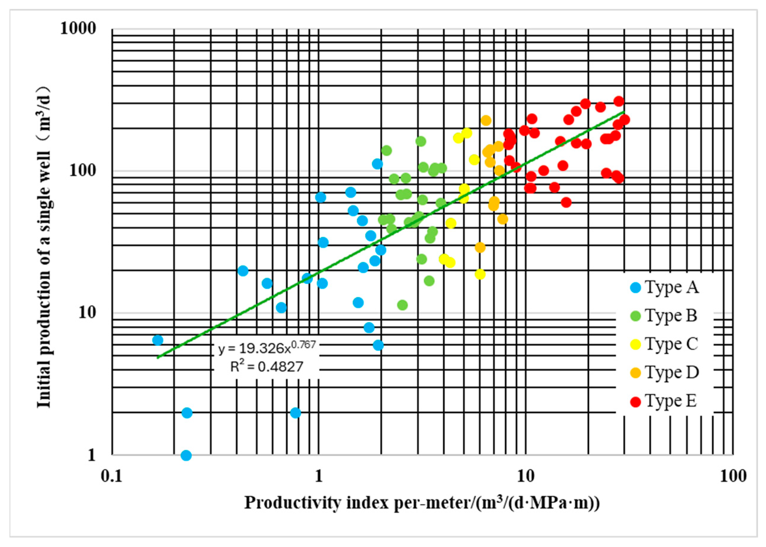
To more truly reflect the original oil production capacity of a single well, the meter oil production index in this paper is calculated using the initial production of single wells. Analysis of the meter oil production index shows that its values in the study area range from 0 to 28.09 m3/(MPa m). Based on the relationship between the meter oil production index and single-well daily production, reservoir productivity types are divided into five categories: Type A (J < 2 m3/(MPa m)), Type B (2 m3/(MPa m) ≤ J < 4 m3/(MPa m)), Type C (4 m3/(MPa m) ≤ J < 6 m3/(MPa m)), Type D (6 m3/(MPa m) ≤ J < 8 m3/(MPa m)), and Type E (J > 8 m3/(MPa m)) (Figure 2). Simplifying the numerical meter oil production index into these five types significantly improves the efficiency and accuracy of subsequent predictions. Among them, Type E reservoirs, with seepage capacity much higher than other types, are typical preferred seepage channels in the study area.
In the study area, Layer I and Layer II are commingled for production, as are Layer III and Layer IV. Therefore, the calculated meter oil production index represents the average meter oil production index of the commingled intervals (either I and II or III and IV). This parameter comprehensively reflects the oil production capacity of the commingled intervals rather than the meter oil production index at any specific point within the reservoir. To calculate the reservoir productivity type at any point in the reservoir, this paper proposes a new method that applies neural network technology to determine the reservoir productivity type at any position based on the productivity type results of the commingled intervals. The specific steps are as follows:
Step 1: Screening sensitive input parameters and performing normalization. Logging data, including natural gamma ray (GR), acoustic (AC), neutron (CN), density (DEN), deep lateral (RT), and shallow lateral logs (RS), contain important information on reservoir lithology, porosity, and other key parameters. Thus, these logging curves are used as inputs in this study. The input parameters of the above logging curves are normalized using the following formula:
α n o r m a l i z a t i o n = α α m i n α m a x α m i n
where
αnormalization—normalized logging curve parameter;
α—actual logging value at any position;
αmax—maximum value in the logging curve of the target layer;
αmin—minimum value in the logging curve of the target layer.
Step 2: Establishing a neural network training model using the average values of logging curves in reservoir intervals and the reservoir productivity types calculated by actual initial production data. The reservoir productivity type of a commingled interval reflects the oil production capacity of the reservoir interval in that well. Therefore, using the Net-to-Gross (NTG) property model as a constraint, the average values of sensitive input parameters in the reservoir intervals of the commingled layers are calculated. These average values correspond to the reservoir productivity of the commingled intervals. Hence, these average values can be used as inputs, and the reservoir productivity types of the commingled intervals as training targets, to train the neural network model. The number of iterations was set to 500, with the error controlled below 5%. Of the dataset, 70% was used as input training parameters, and 30% as supervised data.
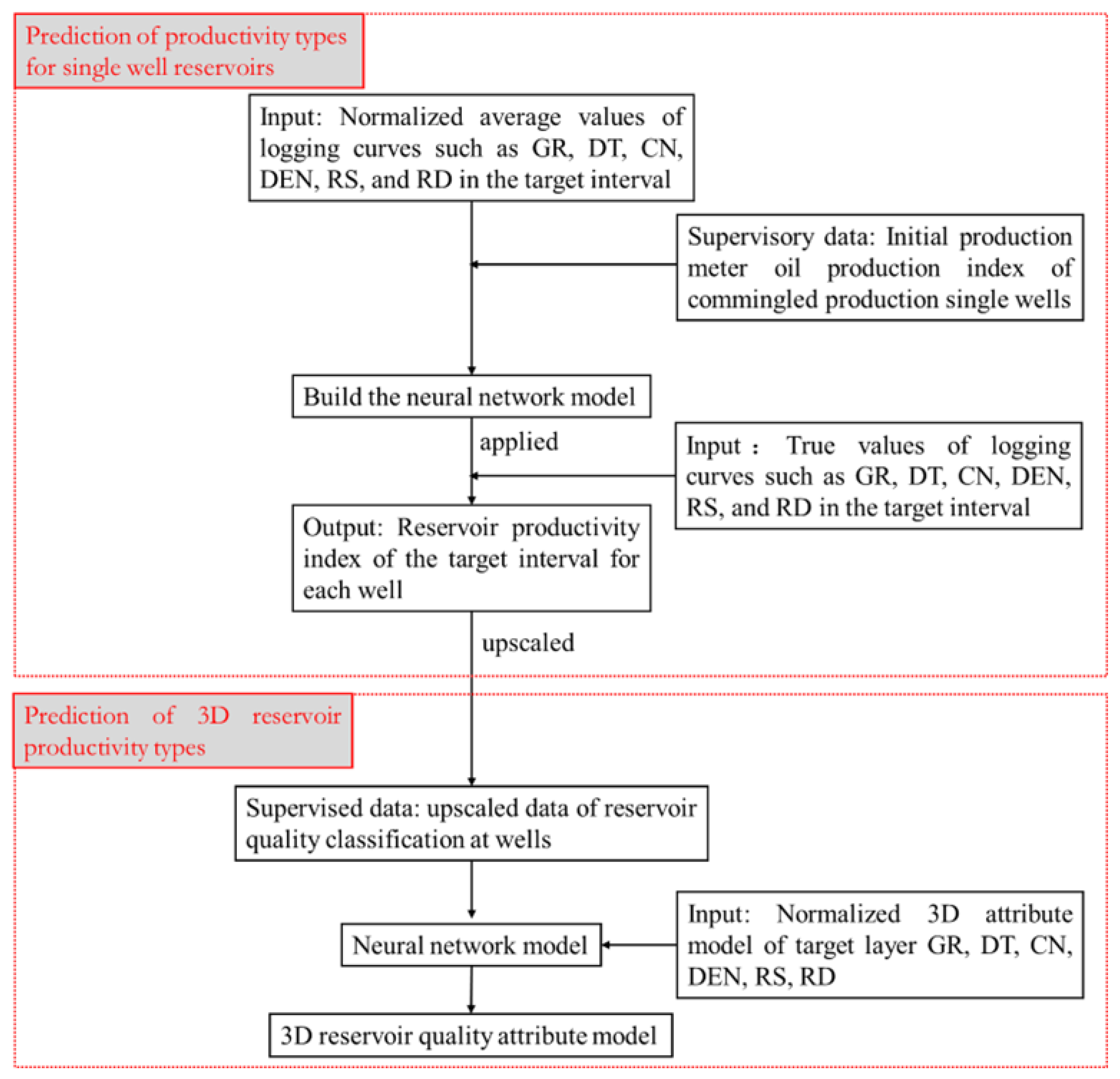
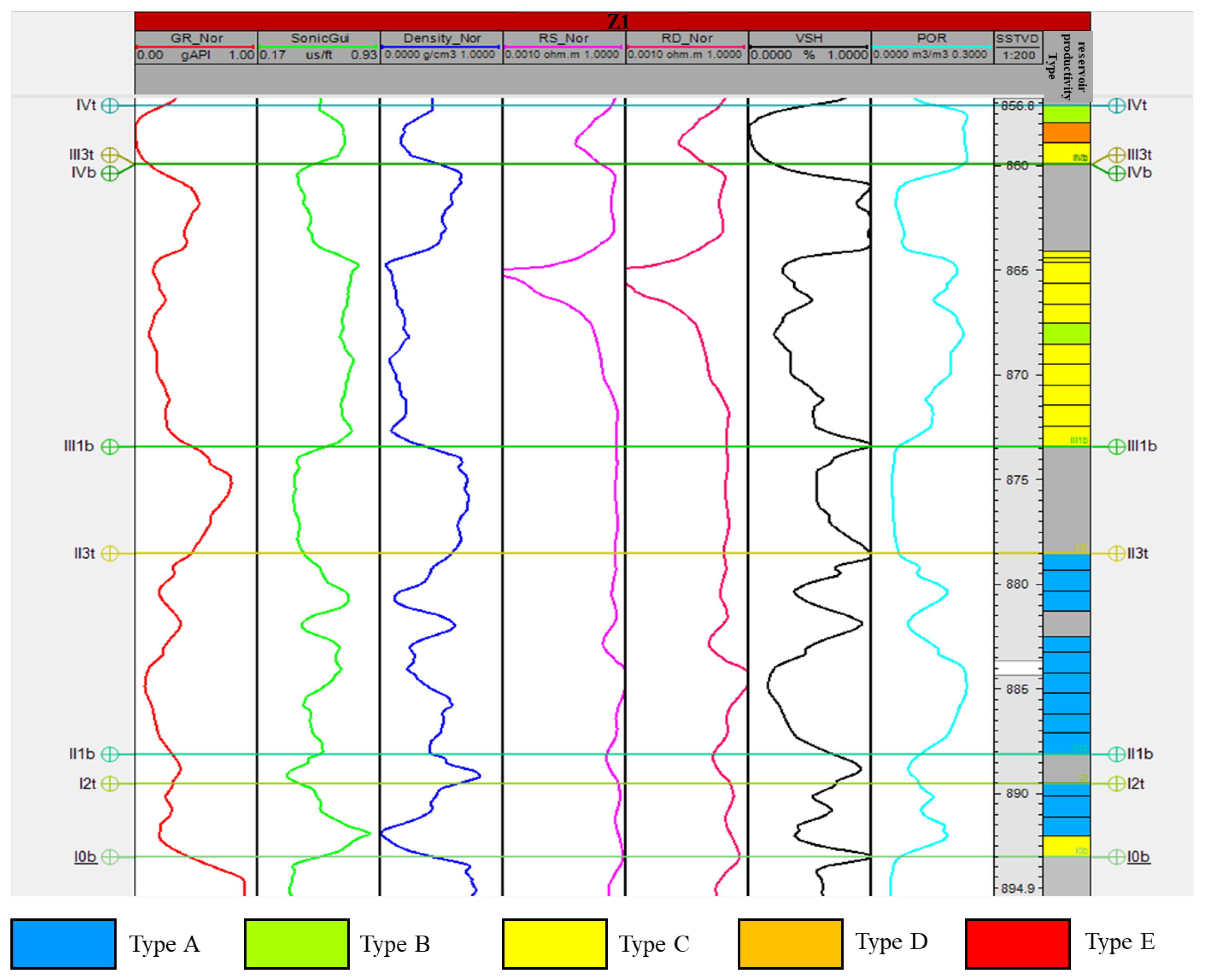
Step 3: Calculating the reservoir productivity type at any position using actual logging data and the trained neural network model. With actual logging curve data as input, the neural network model trained in Step 2 is used to calculate the reservoir productivity type at any position in a single well (Figure 3).
Step 4: Predicting the 3D spatial distribution characteristics of preferred seepage channels. Normalization analysis was conducted using logging data such as gamma ray (GR), sonic (DT), neutron (CN), density (DEN), deep lateral resistivity (RD), and shallow lateral resistivity (RS). Sequential Gaussian simulation was then applied to establish 3D attribute models for different logging curves, respectively. Taking these established 3D attribute models as input and the pre-calculated reservoir productivity types at any position from well data as target constraints, training was performed using neural network technology—with the number of iterations set to 500 and the error controlled to be less than 5%. Among the data, 70% were used as input training parameters and 30% as supervised data, thereby establishing a 3D reservoir productivity attribute model (Figure 3).

4. Results

4.1. Classification Results of Preferred Seepage Channels for Single Well

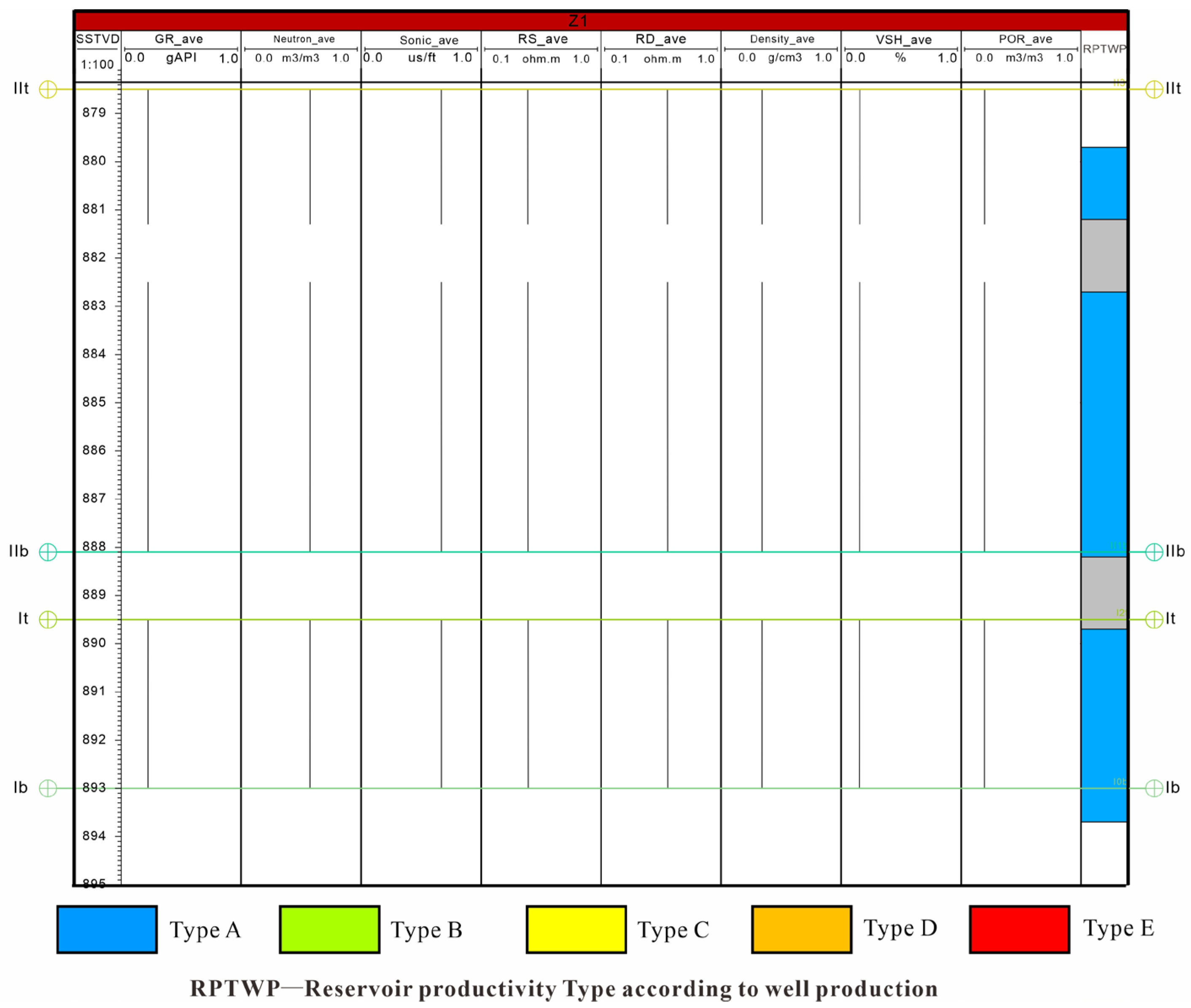
Using the Net-to-Gross (NTG) property model as a constraint, the average values of sensitive input parameters in the reservoir intervals of the commingled layers were calculated (Figure 4). With actual logging curve data as input and the neural network model trained in Step 2, the reservoir productivity type at any position in a single well were obtained (Figure 5). Taking Well Z1 as an example, Layer I and Layer II are dominated by Type A productivity, while Layer III and Layer IV are mainly Type C. This prediction result is consistent with the core permeability test results in the study area, which confirm that the reservoir quality of Layer III and Layer IV is better than that of Layer I and Layer II, indicating good reliability of this method.

4.2. Distribution of Preferred Seepage Channels

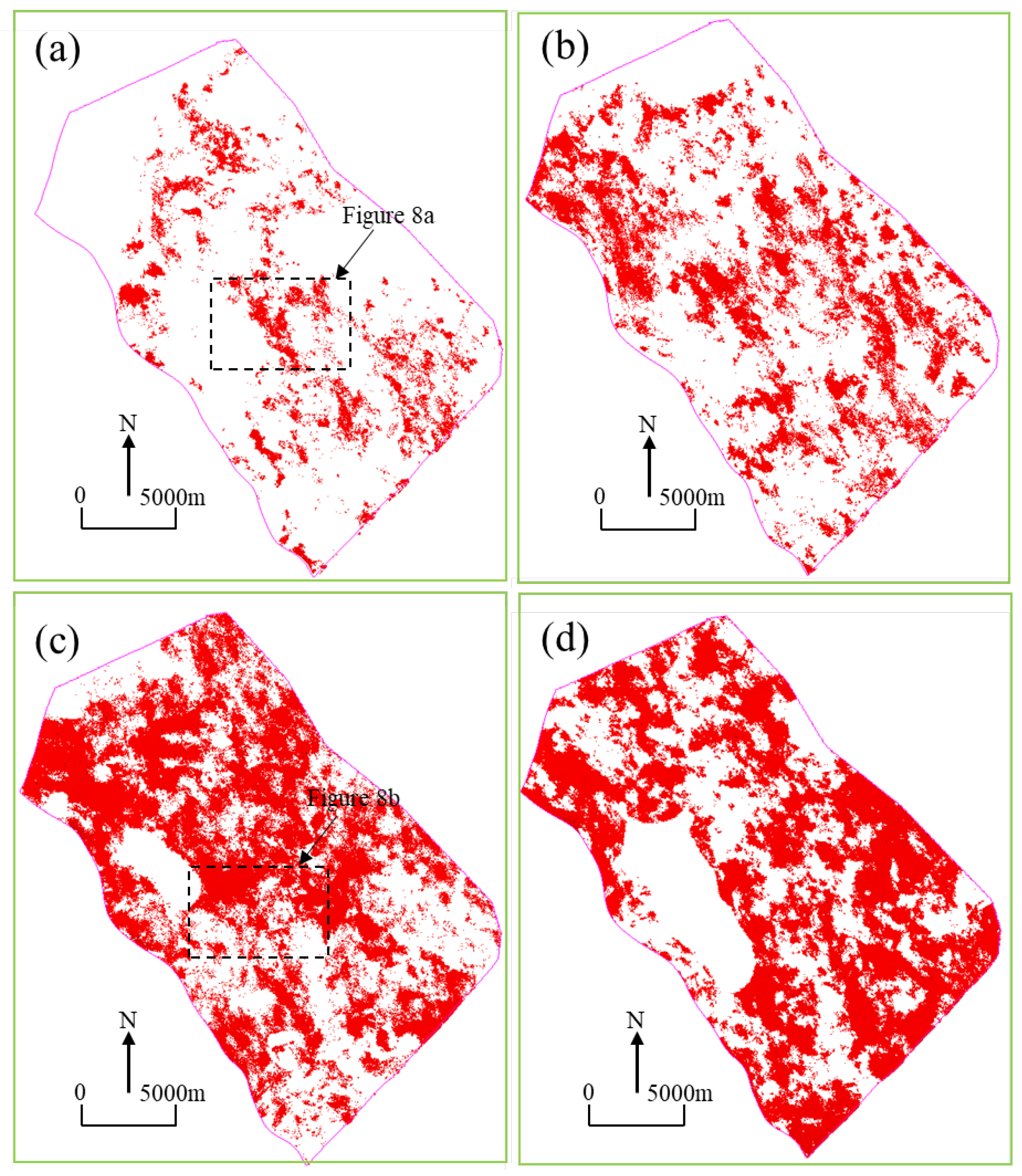
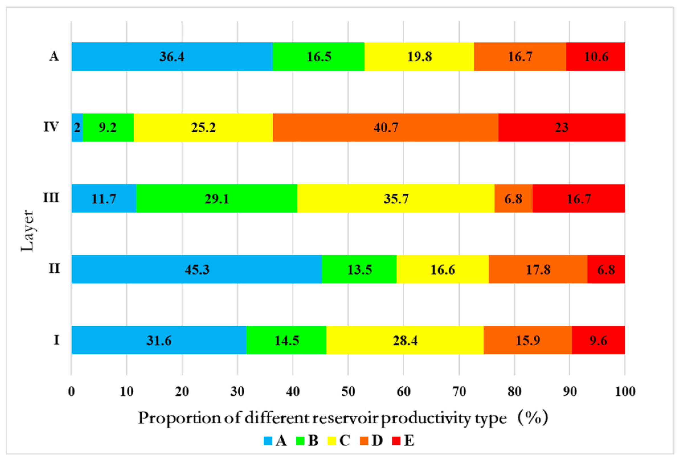
Accurately predicting the distribution of preferred seepage channels is of great significance for formulating oilfield development policies. Therefore, this paper applies neural network technology to predict the 3D spatial distribution of preferred seepage channels in turbidite lobe reservoirs. The results show that, horizontally, reservoir productivity types E and B are sporadically developed in local areas of the study area, while types D, C, and A are widely distributed across the study area (Figure 6). Vertically, reservoir productivity types C, D, and E are relatively well-developed in layers III and IV, whereas types A and B are more common in layers I and II (Figure 7).
Horizontally, preferred seepage channels can be divided into two types: zonal and sheet-like (Figure 8). Zonal preferred seepage channels have an aspect ratio (length to width) greater than 2:1, mainly distributed in layers I and II, with most extending in the southeast-northwest direction, which is consistent with the confirmed provenance direction in the study area [41]. Sheet-like ones have an aspect ratio less than 2:1, mainly distributed in layers III and IV, with no obvious extension direction.
Preferred seepage channels (Type E) account for 10.6% of all reservoirs. Vertically, they are most developed in layer IV, reaching 23.0%, followed by layer III at 16.7%. In addition, the development degree of preferred seepage channels in the study area increases from the bottom to the top (Figure 9).

4.3. Typical Development Pattern of Preferred Seepage Channels

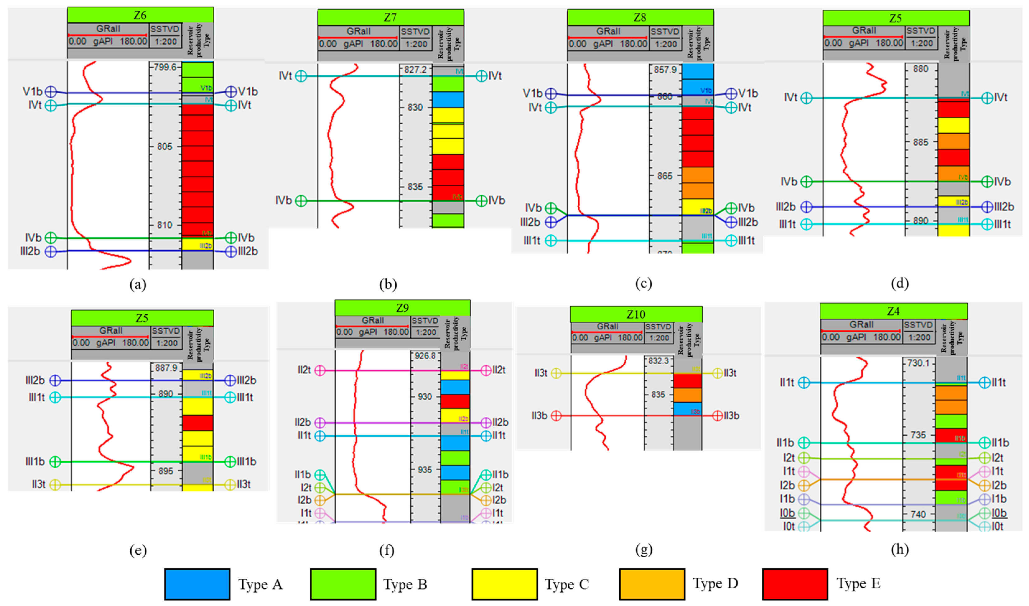
Analysis of the vertical combination patterns of preferred seepage channels reveals four vertical combination patterns, including homogeneous, bottom-dominated, top-dominated, and interbedded patterns. The “homogeneous pattern” refers to a sandbody segment bounded by mudstone layers at both the top and bottom, where all reservoir productivity types are Type E (Figure 10a). The “bottom-dominated pattern” describes a sandbody segment bounded by mudstone layers at both the top and bottom, with Type E reservoir productivity type in the lower part and transitioning to other poorer types toward the top (Figure 10b). The “top-dominated pattern” indicates a sandbody segment bounded by mudstone layers at both the top and bottom, where the top part shows Type E reservoir productivity type while the bottom part consists of other poorer reservoir types (Figure 10c). The “interbedded pattern” refers to a sandbody segment bounded by mudstone layers at both the top and bottom, with randomly distributed Type E strips developed internally (Figure 10d–h).

5. Discussion

5.1. Verification for the Predicted Results of Preferred Seepage Channels

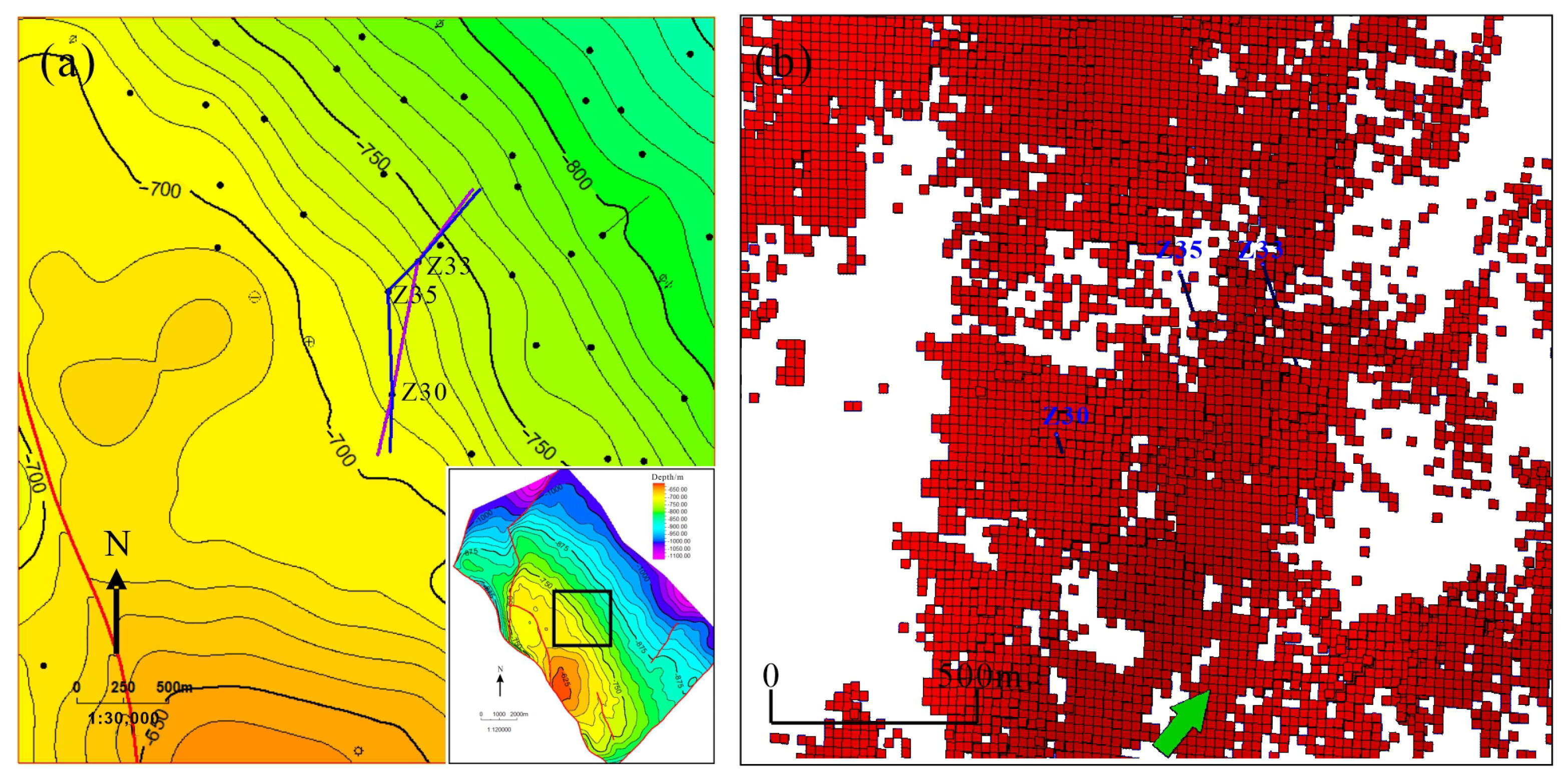
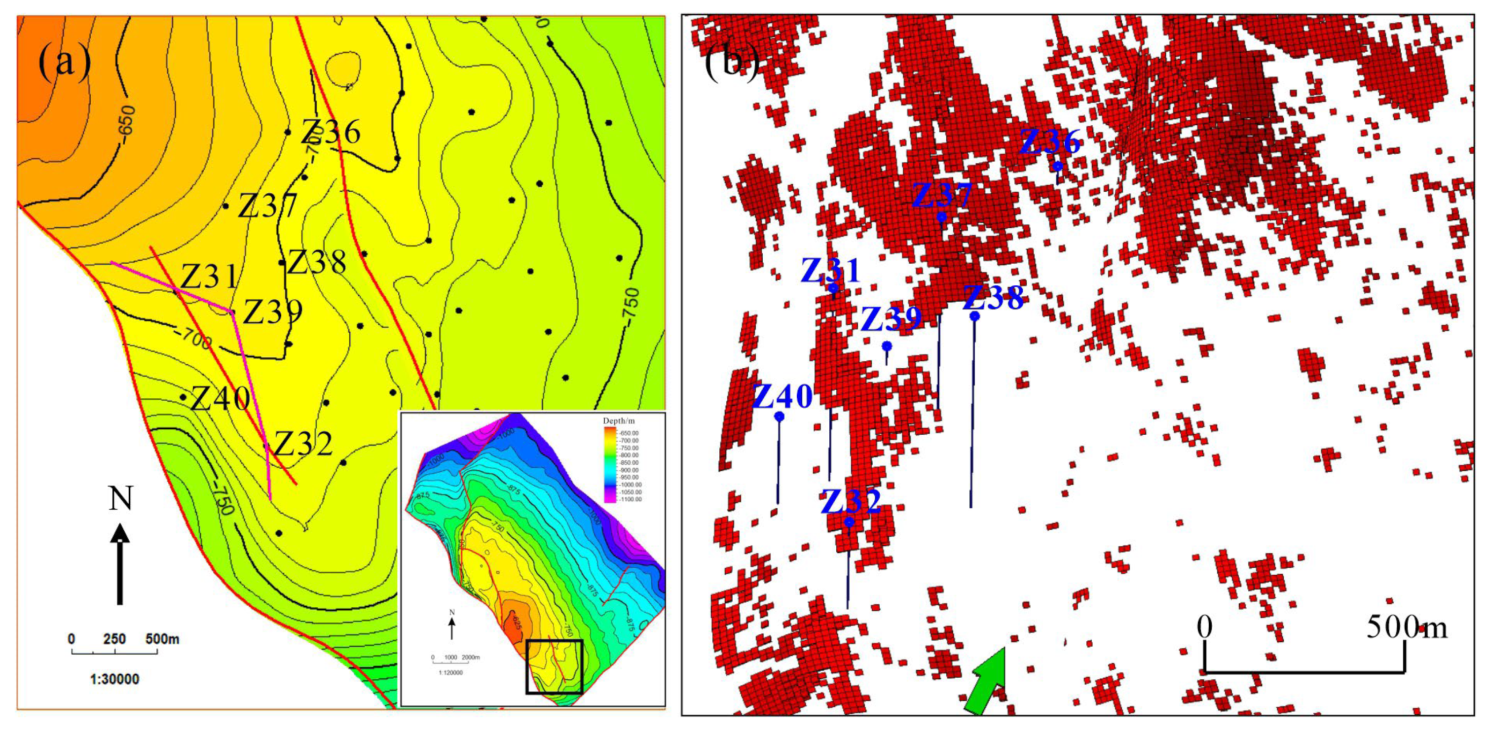
Preferred seepage channels can connect reservoirs between injection wells and production wells, leading to rapid water flooding of production wells in a short period, poor waterflooding efficiency, and low recovery factors. Taking Well Z30 as an example, this well is located at a structural high, with no adjacent injection wells. However, the layers I and II of this well were quickly flooded after being put into production. Analysis suggests that the injected water from Well Z33 rapidly advanced along the preferred seepage channels, leading to the flooding of Well Z30 (Figure 11). Another example is Well Z31 in the southern part of the study area, and tests confirmed that this well was flooded. There are no injection wells around this well, and the nearest injection well is Well Z32, over 1000 m away (Figure 12). Analysis indicates that the flooding of Well Z31 was caused by the connection between the injection well and the production well through preferred seepage channels. The distribution of preferred seepage channels identified in this study is consistent with the understanding of the spatial distribution characteristics of reservoirs in the study area, and it well explains the unique phenomenon where oil wells at the structural high positions is water flooded, while adjacent well at the structural low is producing oil, confirming that the predicted results of preferred seepage channels have good accuracy.
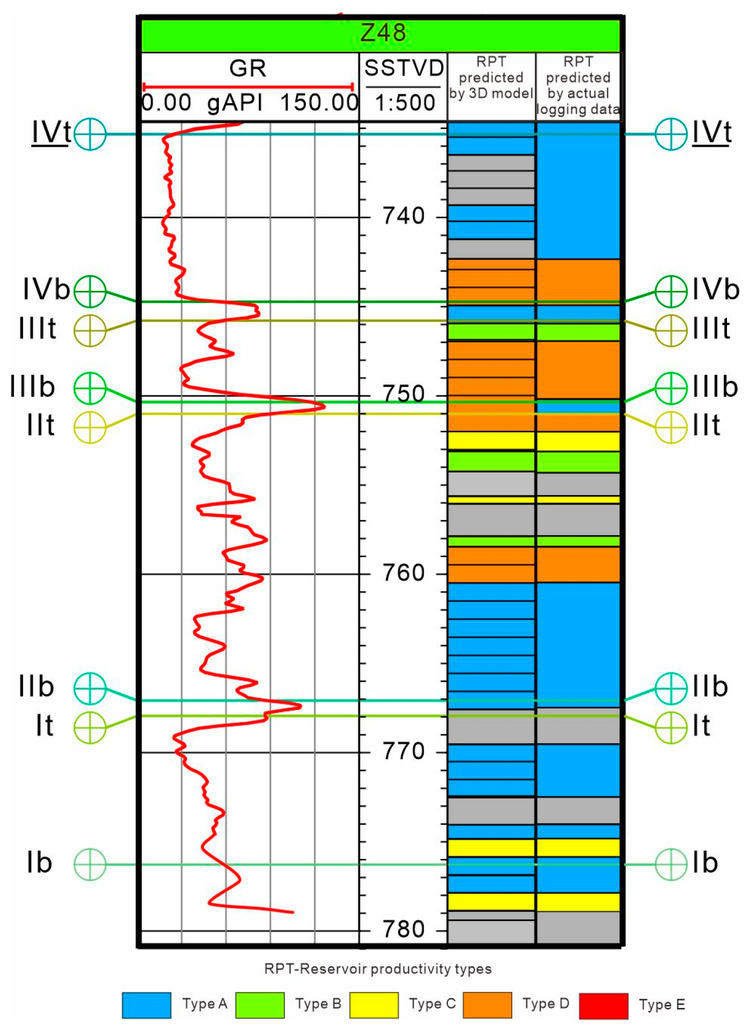
The Z48 well is a recently drilled development well. Prior to drilling, we utilized the reservoir productivity types 3D attribute model to predict the reservoir productivity types of this well. The model shows that the main reservoir productivity types of this well are Type A and Type C (Figure 13). Subsequently, following the completion of drilling and logging, actual logging curves were used to analyze the reservoir productivity types. Compared with the pre-drilling predictions from the reservoir productivity types 3D attribute model, discrepancies were only observed in the intervals of 734–737 m and 741–742 m, with the prediction accuracy reaching 91.2%, confirming high reliability (Figure 13). Furthermore, the perforated interval of Well Z48 is 758–768 m. Production data showed a daily oil production of 35 m3/d and a meter oil production index of 0.175 m3/(d·MPa·m). As illustrated in Figure 2, the reservoir productivity type within the perforated interval of well Z48 is Type A, which aligns with the model’s pre-drill forecast. These results provide strong confirmation of the model’s predictive accuracy.

5.2. Origin of Preferred Seepage Channels

The formation of preferred seepage channels is primarily controlled by three geological factors: sedimentation, diagenesis, and tectonism [42]. Among these, tectonic activity mainly forms fractures in reservoirs, thereby altering their seepage capacity. This process can be regarded as a broad sense of diagenesis. Therefore, the formation of preferred seepage channels in the study area is mainly related to sedimentary and diagenetic factors.

5.2.1. Analysis of Sedimentary Characteristics in the Study Area

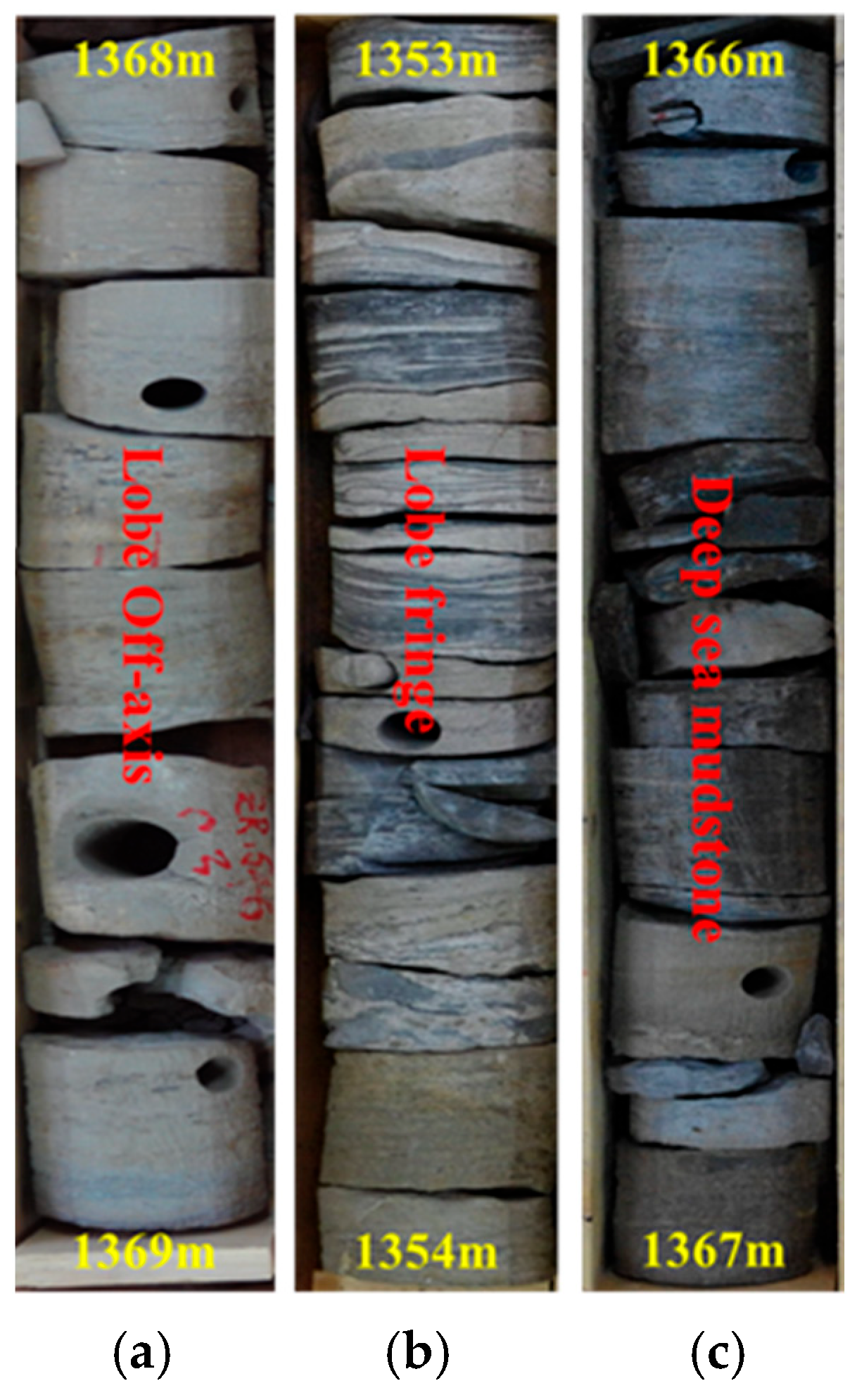
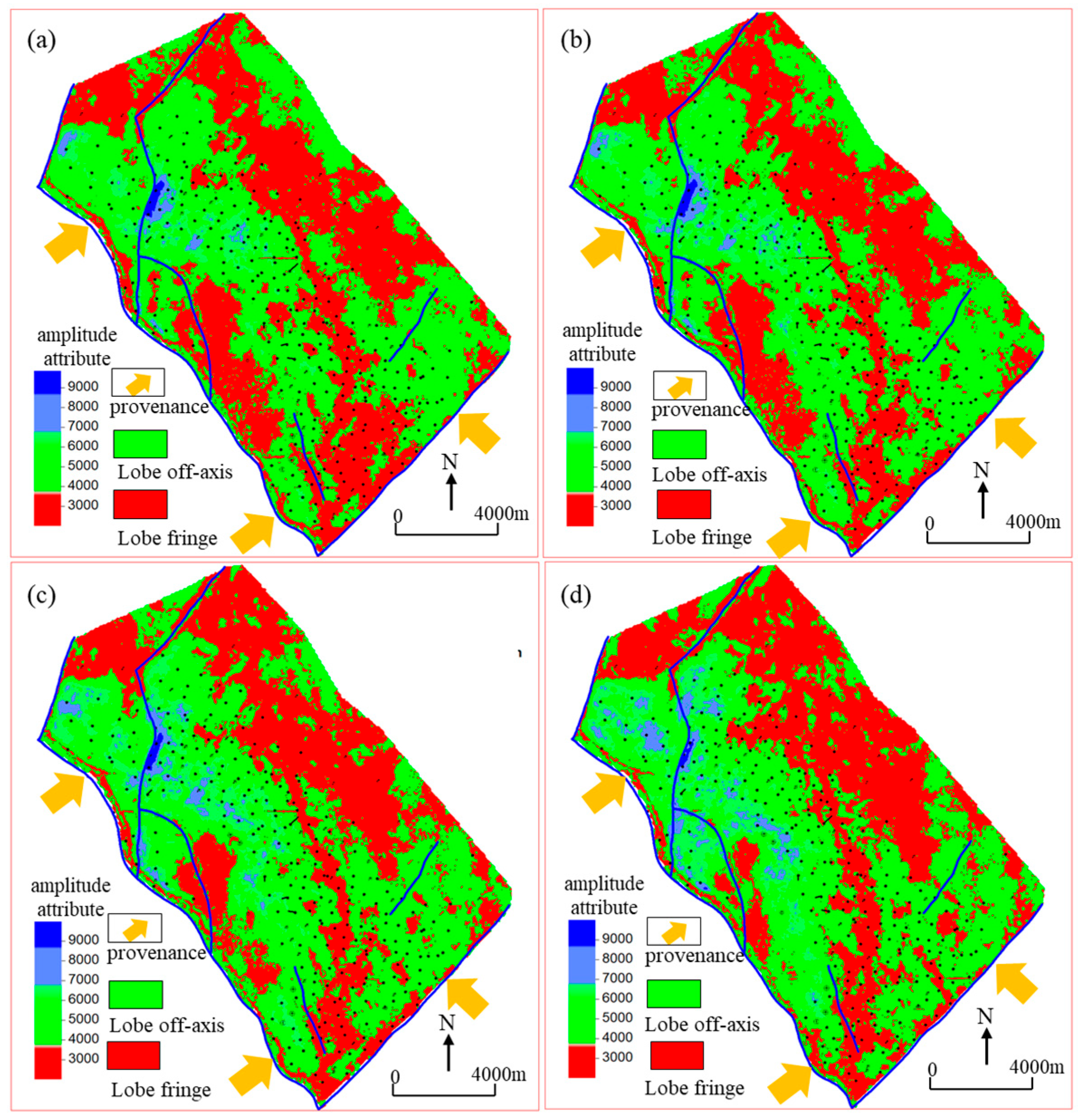
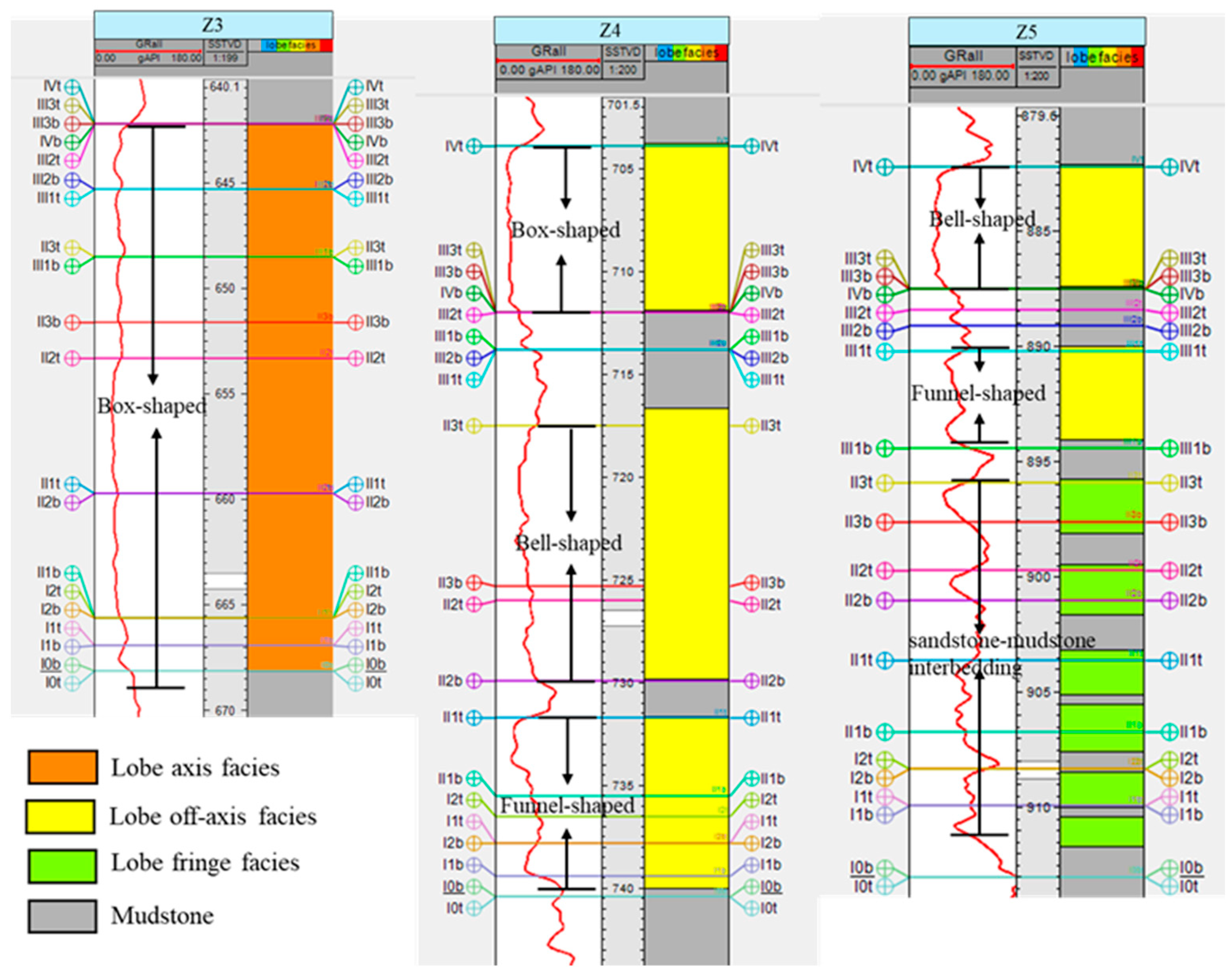
The Z Oilfield comprises marine lobe deposits within a passive continental margin setting [34]. Previous studies define four principal sedimentary facies within these lobes: lobe axis, lobe off-axis, lobe fringe, and deep-sea mudstone [16]. Core data from the study area confirm the presence of lobe off-axis, lobe fringe, and deep-sea mudstone facies (Figure 14). Seismic amplitude attribute analysis delineated the spatial distribution of these facies, revealing four distinct lobe complexes within the oilfield. The study area is predominantly characterized by lobe off-axis and lobe fringe deposits (Figure 15). Provenance analysis [41], indicating sediment sources from the southeast and southwest, corroborates the interpreted distribution of the lobe off-axis facies derived from seismic amplitude attributes.
Sedimentary facies can be further identified by logging curves. The lobe axis facies is characterized by thick-bedded sandstones with almost no mudstone interbeds, and the logging curves are mainly box-shaped, generally smooth (Figure 16). The lobe off-axis facies shows box-shaped, bell-shaped, or funnel-shaped logging curves, which are generally smooth (Figure 16). The lobe fringe facies is characterized by thin single sand bodies and frequent sandstone-mudstone interbeds, with obvious serrated logging curves (Figure 16). The deep-sea mudstone facies is characterized by large intervals of mudstone development, with logging curves showing a continuous mudstone baseline (Figure 16). The logging interpretation results verified that the distribution of sedimentary facies interpreted by seismic amplitude attribute is reliable (Figure 17). Preferred seepage channels are primarily controlled by sedimentary facies, exhibiting a zonal distribution within the off-axis lobe facies, whereas the lobe fringe facies are almost devoid of such channels.

5.2.2. Analysis of Diagenetic Characteristics in the Study Area

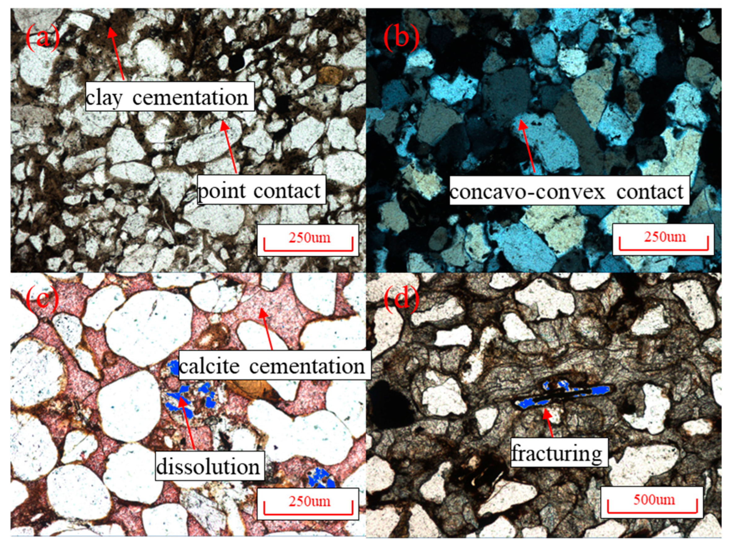
Four types of diagenesis are developed in the study area: compaction, cementation, dissolution, and fracturing (Figure 18). Among them, compaction mainly results in phenomena such as point contact, line contact, or concave-convex contact. Cementation is divided into two types: argillaceous cementation and calcite/dolomite cementation, with dissolution mainly occurring in calcite/dolomite cements. The sandstones in the study area have strong plasticity, and the development degree of fracturing is relatively low. Compaction and cementation reduce reservoir porosity and permeability, while dissolution and fracturing can effectively improve reservoir properties.

5.2.3. Analysis of the Origin of Preferred Seepage Channels

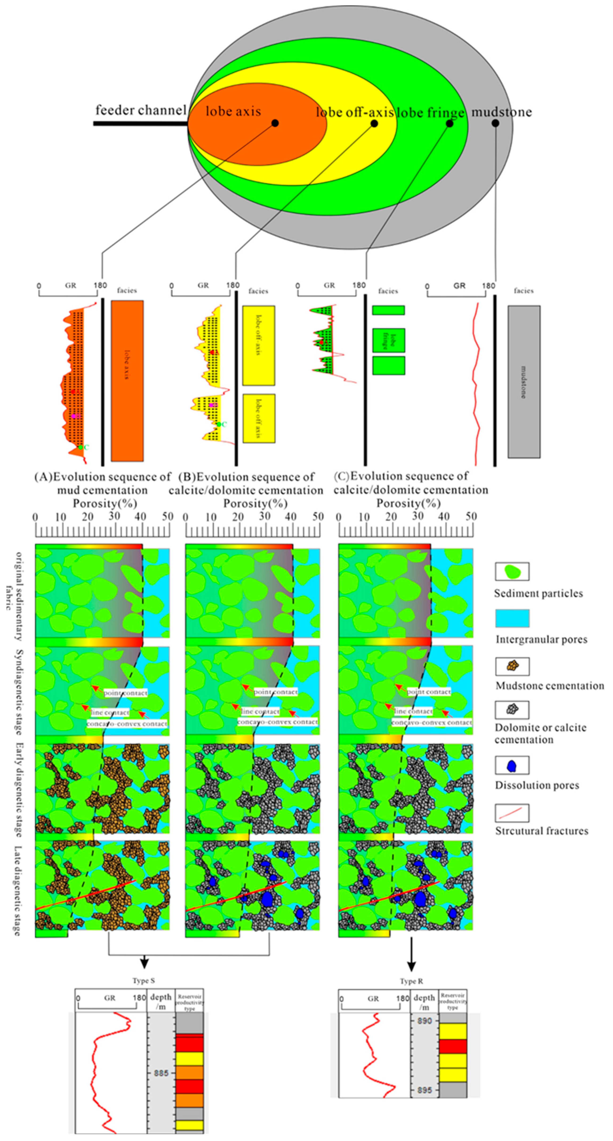
Preferred seepage channels are mainly developed in the lobe axis facies and lobe off-axis facies, while the lobe fringe facies is dominated by reservoir productivity types A and B. This indicates that sedimentary factors are the prerequisite for the formation of preferred seepage channels, and a good sedimentary foundation is crucial for the development of preferred seepage channels. In addition, there are two types of corresponding relationships between reservoir productivity types and natural gamma logging curves. For the first type (defined as Type S), reservoir productivity types correspond well to logging curves: low natural gamma values (illustrated as low shale content) are associated with good reservoir productivity types. This type of reservoir indicates that sedimentary factors are the key to determining reservoir productivity types, meaning the preferred seepage channels are dominantly formed by sedimentary factors (Figure 10a–d). For the second type (defined as Type R), there is no obvious correspondence between reservoir productivity types and logging curves: high natural gamma values (illustrated as high shale content) coexist with good reservoir productivity types. This type of reservoir indicates that in addition to sedimentary factors, diagenetic factors also play a key role in the formation of preferred seepage channels, and the preferred seepage channels are dominantly formed by diagenetic factors (Figure 10a–d). In the study area, when argillaceous cementation is developed, dissolution is rarely observed, meaning the petrophysical properties of such reservoirs cannot be improved by diagenesis. Therefore, it can be concluded that the preferred seepage channels dominated by diagenetic factors are mainly characterized by calcite/dolomite cementation, and the reservoir petrophysical properties are improved by later dissolution (Figure 19).
Preferred seepage channels in the study area exhibit a stacked configuration, with localized development and cross-stratal connectivity (Figure 7). This architecture primarily results from erosional scouring during turbidite lobe formation, which removed mudstone interbeds and facilitated vertical stacking of the lobes.

5.3. Significance of Identifying Preferred Seepage Channels for Guiding Oilfield Development

Due to the unclear understanding of preferred seepage channels before, injection and production wells are connected by such channels, leading to rapid water flooding of production wells and even complete water flooding of newly drilled wells once put into production. This poses significant challenges to oilfield development and well placement. Therefore, the prediction of preferred seepage channels and the detailed characterization of reservoir productivity types in turbidite lobe reservoirs in this study are of great significance for formulating oilfield development policies and tapping remaining oil.
The presence of Preferred seepage channels presents significant difficulties for well positioning. The phenomenon of oil wells at structural highs being flooded indicates that the connection between injection wells and production wells via preferred seepage channels makes it easier for injected water to break through. Under the condition of developed preferred seepage channels, wells connected by such channels exhibit a stronger injection-production correspondence and thus should be classified into the same development well group. In contrast, for wells not connected by preferred seepage channels, even if the distance between injection and production wells is only one well spacing, they may need to be divided into two different well groups due to the insignificant injection-production correspondence. Therefore, the identification of preferred seepage channels has a significant impact on the injection-production relationship.
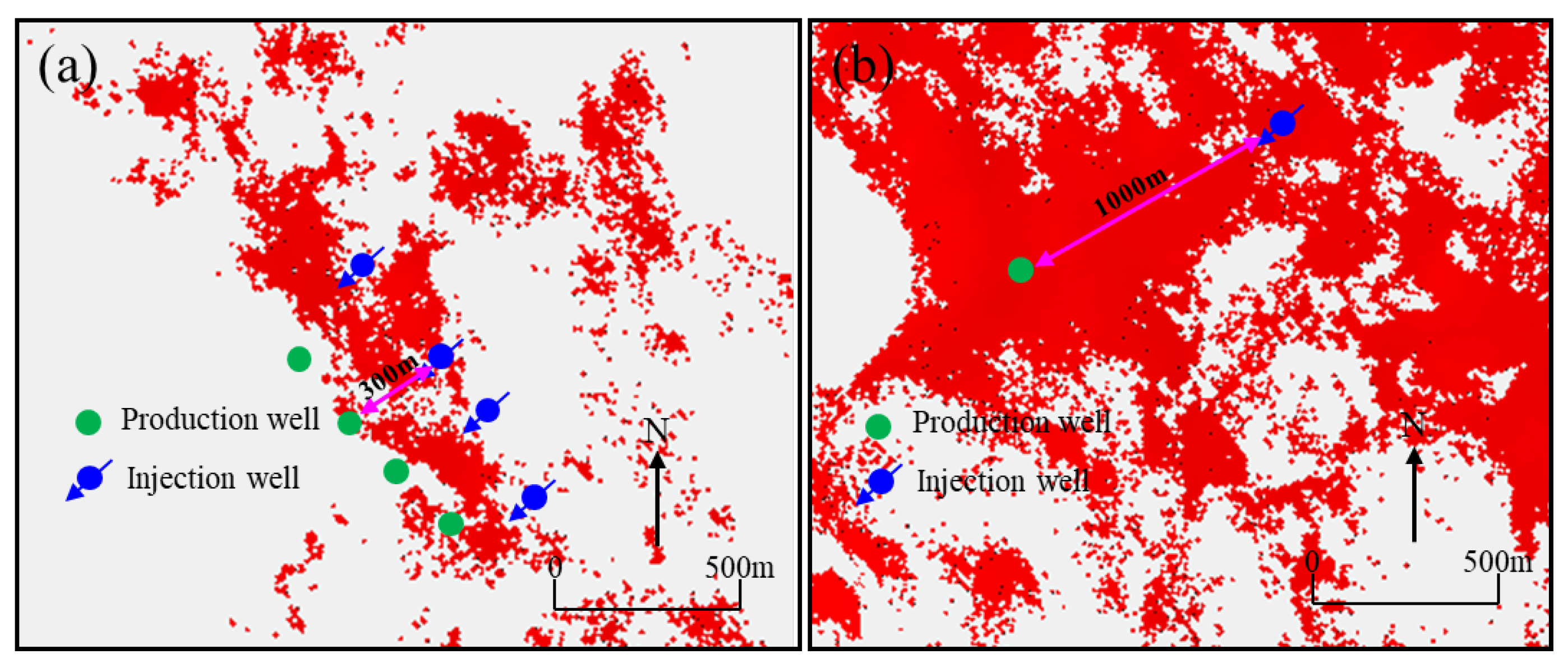
To achieve efficient reservoir development, preventing water channeling caused by preferred seepage channels is crucial for well pattern deployment. Hence, this paper further proposes a “layered and classified” strategy for establishing injection-production relationships. “Layered” refers to establishing injection-production relationships separately for different oil layers, because the distribution characteristics of preferred seepage channels vary significantly among different oil layers. “Classified” means formulating development technical policies based on different types of preferred seepage channels: to prevent rapid flooding of production wells, for zonal preferred seepage channels, the injection-production relationship is established perpendicular to the direction of the channels; for sheet-like preferred seepage channels, the injection-production well spacing should be increased to establish the injection-production relationship (Figure 20).

6. Conclusions

Using core, thin-section, logging, seismic, and production performance data, this study develops a neural network-based method to predict reservoir productivity types in commingled production intervals. It further reveals the genesis and development patterns of preferred seepage channels and discusses their implications for turbidite lobe reservoir development. This method is applicable to all oilfields that have entered the middle and late stages of development.
  • A neural network model is trained using logging parameters from commingled intervals and reservoir productivity types derived from meter oil production index. Applied to actual logging data, this model enables reservoir productivity type prediction at any point within individual wells. By integrating single-well productivity types as training targets with 3D property models built from logging curves, the model predicts reservoir productivity types across the entire reservoir, supporting effective reservoir evaluation.
  • Horizontally, reservoir productivity types E and B are locally scattered, while types D, C, and A are widespread; preferred seepage channels are morphologically classified as zonal or sheet-like. Vertically, types C, D, and E dominate layers III and IV, whereas types A and B are more prevalent in layers I and II. The vertical combination patterns of preferred seepage channels include four types: homogeneous, bottom-dominated, top-dominated, and interbedded patterns.
  • Preferred seepage channels form under the combined control of sedimentation and diagenesis, with two distinct types: Type S, where productivity correlates well with logging curves and is primarily sediment-controlled, and Type R, where productivity shows no clear logging correlation, strongly modified by post-depositional diagenesis. Type S is more common in the Z oilfield.
  • For efficient development, a “layered and classified” strategy is proposed to optimize injection-production relationships: for zonal channels, relationships are established perpendicular to the channel direction to avoid rapid water breakthrough; for sheet-like channels, well spacing is increased to prevent the same issue.

Funding

This work was supported by the CNPC Basic and Prospective Key Scientific and Technological Project (2021DJ24).

Data Availability Statement

All the research data are in the manuscript. Due to newly implemented confidentiality requirements, coordinates cannot be added to the figures.

Acknowledgments

The author would like to thank the anonymous reviewers for their comments and very helpful suggestions.

Conflicts of Interest

The author declares no conflicts of interest.

Abbreviations

The following abbreviations are used in this manuscript:
3DThree-dimensional

References

  1. Jennette, D.; Wawrzyniec, T.; Fouad, K.; Dunlap, D.B.; Meneses-Rocha, J.; Grimaldo, F.; Muñoz, R.; Barrera, D.T.; Williams-Rojas, C.; Escamilla-Herrera, A. Traps and turbidite reservoir characteristics from a complex and evolving tectonic setting, Veracruz Basin, southeastern Mexico. AAPG Bull. 2003, 87, 1599–1622. [Google Scholar] [CrossRef]
  2. Huang, Y. Sedimentary characteristics of turbidite fan and its implication for hydrocarbon exploration in Lower Congo Basin. Pet. Res. 2018, 3, 189–196. [Google Scholar] [CrossRef]
  3. Olagundoye, O.; Akhajeme, E.; Yusuf, M.; Chizea, C.; Spina, V.; Joubert, T.; Parsa, A.; Fashanu, M.; Enuma, C.; Jaiyeola, J. Seismic net-to-gross estimation for a geologic model update: A case study from a turbidite lobe reservoir in the deepwater of the Niger Delta. Interpretation 2024, 12, 35–53. [Google Scholar] [CrossRef]
  4. Fernandes, F.J.D.; de Oliveiraneto, E.R.; Teixeira, L.; Freire, A.F.M.; Lupinacci, W.M. Cycle-consistent convolutional neural network for seismic impedance inversion: An application for high-resolution characterization of turbidites reservoirs. Geoenergy Sci. Eng. 2024, 235, 212709. [Google Scholar] [CrossRef]
  5. Huang, Y.; Tan, X.; Liu, E.; Wang, J.; Wang, J. Sedimentary processes of shallow-marine turbidite fans: An example from the Huangliu Formation in the Yinggehai Basin, South China Sea. Mar. Pet. Geol. 2021, 132, 105191. [Google Scholar] [CrossRef]
  6. Ziyu, L.; Wanli, J.; Jianping, L.; Wei, L.; Aijun, W. Sedimentary composition of turbidite fan and reservoir difference of main units: A case study of Meishan Formation in Qiongdongnan Basin. Chin. J. Geol. 2024, 59, 1268–1279. [Google Scholar]
  7. Santillán-Piña, N.; Arellano-Gil, J.; Gómez-Espinosa, C. Application of Ichnofossils and Microfossils in the Paleoenvironmental Reconstruction of Turbidite Sequences from the Chicontepec Basin, Central-Eastern Mexico; Springer: Cham, Switzerland, 2024; pp. 373–388. [Google Scholar]
  8. Alpak, F.O.; Xue, G. Effects of fine-scale turbidite lobe stratigraphic architecture on dynamic reservoir performance. Mar. Pet. Geol. 2022, 139, 105540. [Google Scholar] [CrossRef]
  9. Li, D.; Gong, C.; Fan, G.; Steel, R.J.; Ge, D.; Shao, D.; Ding, L. Morphological and architectural evolution of submarine channels: An example from the world’s largest submarine fan in the Bay of Bengal. Mar. Pet. Geol. 2023, 155, 106368. [Google Scholar] [CrossRef]
  10. Zhang, H.; Zhong, G.; Zhang, L.; Wang, B.; Lei, Z.; Guan, Y.; Yao, Y. The Guangya submarine fan in the South China Sea: A distinctive channelized slope-through fan. Geomorphology 2024, 452, 109116. [Google Scholar] [CrossRef]
  11. Macdonald, H.A.; Peakall, J.; Wignall, P.B.; Best, J. Sedimentation in deep-sea lobe-elements: Implications for the origin of thickening-upward sequences. J. Geol. Soc. Lond. 2011, 168, 319–332. [Google Scholar] [CrossRef]
  12. Mulder, T.; Etienne, S. Lobes in deep-sea turbidite systems: State of the art. Sediment. Geol. 2010, 229, 75–80. [Google Scholar] [CrossRef]
  13. Prélat, A.; Hodgson, D.M.; Flint, S.S. Evolution, architecture and hierarchy of distributary deep-water deposits: A high-resolution outcrop investigation from the Permian Karoo Basin, South Africa. Sedimentology 2009, 56, 2132–2154. [Google Scholar] [CrossRef]
  14. Dennielou, B.; Droz, L.; Babonneau, N.; Jacq, C.; Bonnel, C.; Picot, M.; Le Saout, M.; Saout, Y.; Bez, M.; Savoye, B.; et al. Morphology, structure, composition and build-up processes of the active channel-mouth lobe complex of the Congo deep-sea fan with inputs from remotely operated underwater vehicle (ROV) multibeam and video surveys. Deep Sea Res. Part II 2017, 142, 25–49. [Google Scholar] [CrossRef]
  15. Liu, Q.; Kneller, B.; Fallgatter, C.; Buso, V.V. Quantitative comparisons of depositional architectures of unconfined and confined turbidite sheet systems. Sediment. Geol. 2018, 376, 72–89. [Google Scholar] [CrossRef]
  16. Jamil, M.; Siddiqui, N.A.; Rahman, A.H.B.A.; Ibrahim, N.A.; Ismail, M.S.B.; Ahmed, N.; Usman, M.; Gul, Z.; Imran, Q.S. Facies heterogeneity and lobe facies multiscale analysis of deep-marine sand-shale complexity in the West Crocker Formation of Sabah Basin, NW Borneo. Appl. Sci. 2021, 11, 5513. [Google Scholar] [CrossRef]
  17. Mohdradzir, N.A.; Ali, C.A.; Mohamed, K.R. Sedimentological analysis of the turbidite sequence in the northern part of the west crocker formation, Northwest Sabah. Appl. Sci. 2022, 12, 12149. [Google Scholar] [CrossRef]
  18. Zhang, J.; Wu, S.; Fan, T.; Fan, H.; Jiang, L.; Chen, C.; Wu, Q.; Lin, P. Research on the architecture of submarine-fan lobes in the Niger Delta Basin, offshore West Africa. J. Palaeogeogr. 2016, 5, 185–204. [Google Scholar] [CrossRef]
  19. Doughty-Jones, G.; Mayall, M.; Lonergan, L. Stratigraphy, facies, and evolution of deep-water lobe complexes within a salt-controlled intraslope minibasin. AAPG Bull. 2017, 101, 1879–1904. [Google Scholar] [CrossRef]
  20. Liu, Q.; Kneller, B.; Fallgatter, C.; Buso, V.V. Depositional processes and impact on reservoir quality in deepwater Paleogene reservoirs, US Gulf of Mexico. AAPG Bull. 2015, 99, 1635–1648. [Google Scholar] [CrossRef]
  21. Umar, M.; Friis, H.; Khan, A.S.; Kassi, A.M.; Kasi, A.K. The effects of diagenesis on the reservoir characters in sandstones of the Late Cretaceous Pab Formation, Kirthar Fold Belt, southern Pakistan. J. Asian Earth Sci. 2011, 40, 622–635. [Google Scholar] [CrossRef]
  22. Dons, T.; Jørgensen, O.; Gommesen, L. Observations and quantitative analyses of waterflood patterns in a chalk reservoir using seismic data, Halfdan Field, Danish North Sea. In Proceedings of the SPE Offshore Europe Oil and Gas Conference and Exhi-bition, Aberdeen, UK, 4–7 September 2007. SPE-108531-MS. [Google Scholar]
  23. Wen-Min, Z.; Zhi-Yong, C.; Yan, Z.; Dan, W.; De-Li, Z. Research on Identification and Control of Dominant Seepage Channels in Medium and Low Permeability Reservoirs; Springer: Cham, Switzerland, 2023; pp. 588–598. [Google Scholar]
  24. Liu, H.; Shi, K.; Liu, B.; Song, X.; Guo, R.; Li, Y.; Wang, G.; Wang, H.; Shen, Y. Characterization and identification of bioturbation-associated high permeability zones in carbonate reservoirs of Upper Cretaceous Khasib Formation, AD oilfield, central Mesopotamian Basin, Iraq. Mar. Pet. Geol. 2019, 110, 747–767. [Google Scholar] [CrossRef]
  25. Cross, N.E.; Burchette, T.P. Middle Eastern carbonate reservoirs–the critical impact of discrete zones of elevated permeability on reservoir performance. Geol. Soc. Spec. Publ. 2025, 548, 65–113. [Google Scholar] [CrossRef]
  26. Chen, C.; Song, X.; Li, J. Dominant flow channels of point-bar reservoirs and their control on the distribution of remaining oils. Acta Pet. Sin. 2012, 33, 257–263. [Google Scholar]
  27. Yi, X.; Zhang, M.; Mu, G. Microscopic Distribution and Development Strategy of Residual Oil in Tight Sandstone. Processes 2023, 11, 1907. [Google Scholar] [CrossRef]
  28. Shunming, L.I.; Hongwen, D.; Xiuli, W.U.; Haina, Z. Sedimentary characteristics and evolution of Lower Devonian in Zarzaitine oilfield, eastern Algeria. Pet. Explor. Dev. 2006, 33, 383–387. [Google Scholar]
  29. Chen, L. Study on Petrological Characteristics of F4 Reservoir in Zarzaitine Oilfield. Inn. Mong. Petrochem. Ind. 2009, 11, 133–136. [Google Scholar]
  30. Li, C.; Li, W.; Ye, H.; Zhu, Q.; Shan, X.; Wang, S.; Wang, D.; Zhang, Z.; Wang, H.; Zhou, X. Reservoir Architecture of Turbidite Lobes and Remaining Oil Distribution: A Study on the B Formation for Z Oilfield of the Illizi Basin, Algeria. Processes 2025, 13, 805. [Google Scholar] [CrossRef]
  31. Sun, G. Enhanced Oil Recovery Technology Research and Application of F4 Reservoir in Zarzaitine Oilfield in Algeria; China University of Geoscience (Beijing): Beijing, China, 2013; pp. 1–44. [Google Scholar]
  32. Galeazzi, S.; Point, O.; Haddadi, N.; Mather, J.; Druesne, D. Regional geology and petroleum systems of the Illizi–Berkine area of the Algerian Saharan Platform: An overview. Mar. Pet. Geol. 2010, 27, 143–178. [Google Scholar] [CrossRef]
  33. Zheng, W.; Wu, X.; Deng, H. Stratigraphy and Facies Distribution of Lower Devonian F4 Unit in Zarzaitine Oilfield, Illizi Basin, Algeria. Earth Sci./Diqiu Kexue 2012, 37, 181–189. [Google Scholar]
  34. Zhang, Z.M.; Li, Y.F.; Zheng, N.X.; Cao, Z.; Lu, X.Y.; Li, Z.F.; Sun, R.M.; Xia, C.S.; Li, L.; Niu, B.; et al. Early Paleozoic lithofacies palaeogeography evolution characteristics of Ghadames Basin in North Africa. J. Palaeogeogr. 2024, 26, 45–57. [Google Scholar]
  35. Li, L. Study on Heterogeneity of F4 Reservoir in Zarzaitine Oilfield. China Acad. J. Electron. Publ. House 2012, 10, 114. [Google Scholar]
  36. Zhang, Q.; Li, Y.; Li, B.; Liu, Z.; Wei, J.; Zhou, J. Identification methods and development strategy study of thief zone in reef-bank carbonate reservoirs:A case study of the Mishrif reservoir in Rumaila oilfield. Pet. Geol. Recovery Effic. 2016, 23, 29–34. [Google Scholar]
  37. Wang, J.; Fan, Z.; Zhao, L.; Chen, Y.; Zhang, A.; Zhang, X.; Guo, X.; Li, Y. A new method for identification of flow units of sandstone reservoir based on reservoir performance and its application in the Akshabulak oilfield, Kazakhstan. Earth Sci. Front. 2023, 30, 88–99. [Google Scholar]
  38. Fahad, A.A.; Ali, M.A.; Mustafa, M.S. Evaluation of super-k wells performance using fluid flow index in Ghawar field. In Proceedings of the SPE Middle East Oil Show, Manama, Bahrain, 17–20 March 2001. SPE-68162-MS. [Google Scholar]
  39. Li, B.; Najeh, H.; Lantz, J.; Rampurawala, M.A.; Gok, I.; Al-Khabbaz, M. Detecting thief zones in carbonate reservoirs by integrating borehole images with dynamic measurements: Case study from the Mauddud reservoir, North Kuwait. Soc. Pet. Eng. Reserv. Eval. Eng. 2010, 13, 193–202. [Google Scholar] [CrossRef]
  40. Feng, Q.; Wang, S.; Wang, S.; Wang, Y.; Chen, D. Identification of thief zones by dimensionless pressure index in waterfloods. In Proceedings of the SPE Enhanced Oil Recovery Conference, Kuala Lumpur, Malaysia, 16 July 2011. SPE-143926-MS. [Google Scholar]
  41. Wu, X.L.; Zheng, W.B.; Deng, H.W. Stratigraphy and Distribution of Gravity Flow Deposition, Lower Devonian F4 Unit, Zarzaitine Oilfield, Illizi Basin, Algeria. Pet. Sci. Technol. 2012, 30, 1151–1162. [Google Scholar] [CrossRef]
  42. Chen, G.; Meng, Y.; Huan, J.; Wang, Y.; Zhang, L.; Xiao, L. Distribution and origin of anomalously high permeability zones in Weizhou formation, Weizhou 12-X oilfield, Weixinan Sag, China. Earth Sci. Inf. 2021, 14, 2003–2015. [Google Scholar] [CrossRef]
Figure 1. Regional geographical location and structural characteristics of Z Oilfield, Algeria. (a) Geographical map of Algeria; (b) Regional structural map of Z Oilfield; (c) Structural characteristics of Z Oilfield; (d) Stratigraphic column of Z Oilfield.
Geosciences 15 00328 g001
Figure 2. Classification criteria chart for single-well reservoir productivity types.
Geosciences 15 00328 g002
Figure 3. Flowchart for calculating reservoir productivity types of single wells and arbitrary positions in 3D space.
Geosciences 15 00328 g003
Figure 4. Input data and supervised data for neural network model training.
Geosciences 15 00328 g004
Figure 5. Results of reservoir productivity types predicted by neural network at arbitrary positions in single wells.
Geosciences 15 00328 g005
Figure 6. Planar distribution characteristics of preferred seepage channels in different layers of Formation A in Z Oilfield. (a) Planar distribution characteristics of preferred seepage channels in layer I. (b) Planar distribution characteristics of preferred seepage channels in layer II. (c) Planar distribution characteristics of preferred seepage channels in layer III. (d) Planar distribution characteristics of preferred seepage channels in layer IV.
Geosciences 15 00328 g006
Figure 7. Well section of different reservoir productivity types. (a) Profile of reservoir productivity types perpendicular to the sedimentary provenance direction; (b) Profile of reservoir productivity types parallel to the sedimentary provenance direction.
Geosciences 15 00328 g007
Figure 8. Types of preferred seepage channel. (a) Zonal shape preferred seepage channels. The location was shown in Figure 6. (b) Sheet-like shape preferred seepage channels. The location was shown in Figure 6.
Geosciences 15 00328 g008
Figure 9. Development proportion of different reservoir productivity types in different layers of Formation A in Z Oilfield.
Geosciences 15 00328 g009
Figure 10. Vertical combination patterns of preferred seepage channels in Formation A of Z Oilfield. (a) homogeneous preferred seepage channel; (b) bottom-dominated preferred seepage channel; (c) top-dominated preferred seepage channel; (d) interbedded preferred seepage channel; (eh) interbedded preferred seepage channel.
Geosciences 15 00328 g010
Figure 11. Relationship between rapidly water-flooded wells and preferred seepage channels in the Z8 well block of Layer A in Z Oilfield. (a) The location of well Z30 and well Z33. (b) The distribution of preferred seepage channels in well Z30 block.
Geosciences 15 00328 g011
Figure 12. Relationship between rapidly water-flooded wells and preferred seepage channels in the well Z31 block of Formation A in Z Oilfield. (a) The location of well 31 and well 32. (b)The distribution of preferred seepage channels in well 31 block.
Geosciences 15 00328 g012
Figure 13. Comparison between 3D model prediction results and logging curve prediction results for well Z48.
Geosciences 15 00328 g013
Figure 14. Characteristics of core sedimentary microfacies in Well Z2 of Z Oilfield. (a) Off-axis lobe sedimentary microfacies; (b) Lobe fringe facies; (c) Deep-sea mudstone facies.
Geosciences 15 00328 g014
Figure 15. Planar maps of sedimentary facies in different sublayers identified by seismic amplitude attributes. (a) Planar map of sedimentary facies in layer IV identified by seismic amplitude attributes; (b) Planar map of sedimentary facies in layer III identified by seismic amplitude attributes; (c) Planar map of sedimentary facies in layer II identified by seismic amplitude attributes; (d) Planar map of sedimentary facies in layer I identified by seismic amplitude attributes.
Geosciences 15 00328 g015
Figure 16. Logging curve identification characteristics of different sedimentary microfacies in Formation A of Z Oilfield.
Geosciences 15 00328 g016
Figure 17. Well section of sedimentary microfacies in Formation A of Z Oilfield.
Geosciences 15 00328 g017
Figure 18. Diagenetic types in Well Z1 of Formation A in Z Oilfield. (a) Punctate contact formed by argillaceous cementation and compaction; (b) Concavo-convex contact formed by compaction; (c) Calcite cementation and dissolution; (d) Fractures formed by tectonism.
Geosciences 15 00328 g018
Figure 19. Genetic model of preferred seepage channels in turbidite lobe reservoirs.
Geosciences 15 00328 g019
Figure 20. Development strategies for different types of preferred seepage channels in Formation A of Z Oilfield: (a) well pattern development strategy for zonal preferred seepage channels; (b) well pattern development strategy for sheet-like preferred seepage channels.
Geosciences 15 00328 g020
Disclaimer/Publisher’s Note: The statements, opinions and data contained in all publications are solely those of the individual author(s) and contributor(s) and not of MDPI and/or the editor(s). MDPI and/or the editor(s) disclaim responsibility for any injury to people or property resulting from any ideas, methods, instructions or products referred to in the content.