1. Introduction
Construction loads are transferred from superstructures to the ground through soil–pile interactions, which are influenced by the study of interface soil–pile and load–settlement interdependency that are subsequently typical of deep foundations, pavement–subgrade behaviour and tunnelling. The present study uses Randolph’s (1979) method via analytical solutions to back-analyse the pile load–settlement behaviour to demonstrate this concept [
1].
The proposed viaduct at Jining Avenue plays an essential role in the urban high-speed traffic networks located on the G105 and G327 national highways in Jining. It comprises eight parallel ramps, with a length of 7.25 km, widths between 25.5–33.5 m and an estimated road area of 240,400 m
2. The present study focuses on a section of the proposed project, from the Western Circumferential Expressway to Ningan Avenue (as shown in
Figure 1).
Considering the complexity of the subsurface conditions and the safety of the adjacent structure, this viaduct project selected cast in-situ pile foundations for load transfer from the shallower, looser sand stratum to the deeper, denser sand stratum. Meanwhile, the dynamic lateral loads derived from the vehicles and the significant vertical dead loads required a large pile bearing capacity to support the superstructure. Therefore, this study included cast in-situ bored piles that were constructed with 45–65 m length and diameters of 1 m and 1.5 m. Consequently, polymer slurry was used to stabilise the bored cavity during the wet construction technique, thus affecting the soil properties and pile load–settlement response.
As field test results are influenced by various factors, reliable field pile tests, such as conventional static load tests (compression-proof load test) and bi-directional static load tests (BDSLTs), are used to further verify pile performance. Conventional static load tests (SLTs) have been frequently used to validate the ultimate pile capacities of bored piles; however, using the kentledge system for conventional SLTs might entail safety risks, such as the kentledge platform toppling. In the present study, the conventional SLT’s hydraulic system is required to provide a large reaction force. An extensive kentledge reaction system must thus be installed, such as the concrete blocks and supporting steel reaction beams. Due to space limitations at the project site, a limited workspace was available for erecting the bulky kentledge system. Therefore, the BDSLT was deemed a viable alternative to the kentledge load test.
Comprising Osterberg cells, or equivalent ‘supercells’, the BDSLT was originally developed by Osterberg [
2], and it has been widely adopted as a proof test due to its proven accuracy and reliability [
3,
4,
5]. It involves welding the load cell at a specific location on the pile reinforcement cage, thus providing steady vertical load increments in a bi-directional fashion to the in-situ pile. Such bi-directional load application effectively ‘splits’ the pile into an upper and lower portion with respect to the supercell location [
6]. The embedded cell is then loaded to generate the load–displacement relationships, which are then used to interpret the mobilisation of pile resistance and soil–structure behaviour.
Setting up a BDSLT requires a small footprint, thus reducing installation difficulty and guaranteeing construction safety. It can also be used to measure end bearing capacity or shaft capacity independently and accurately, thereby contributing to a clear understanding of pile load–settlement responses so that engineers can conduct optimum pile designs; however, as the supercells cannot be retrieved after testing, due to being sacrificial, the BDSLT might be relatively costly and thus not ideal for small-scale projects [
7]. To solve this issue and improve understanding of the BDSLT, Baca (2020, 2021) conducted several studies concerning numerical simulation and laboratory scale tests in medium-density sand [
6,
8]. Baca (2017) also validated the practicability of numerical simulation and laboratory scale tests with field tests [
9].
Typically, the BDSLT only uses a single supercell installed in a single pile; however, in cases in which the piles are extensively long, a single supercell might not be able to fully mobilise pile end bearing and shaft capacities. Therefore, this study focused on two supercells to provide sufficient reaction forces to mobilise the ultimate capacity of the 60 m-long bored pile being proof tested. In the reaction system’s preliminary design, the supercell location was determined by the estimated improved bearing capacity via post-grouting technology.
This article used analytical solutions based on reliable soil characterisation to present a case study on the design methodology used to interpret the BDSLT field test results. Four BDSLT tests were conducted with different pile lengths and diameters. Further, conventional analytical solutions, such as the Alpha and Beta methods, were assessed in comparison to the results derived using the enhanced, modified closed-form analytical solutions [
7] to more accurately determine the load–settlement responses derived from the BDSLTs.
2. Geotechnical Conditions
As aligned with the local Chinese standard (Code for Geotechnical Investigation) and site investigations, the soil layers primarily comprised (1) silty sand that was well graded, with standard penetration test (SPT) N values ranging from 39 to 143 (increased with larger overburden pressure), being selected as the bearing stratum around the pile end; (2) silt that is dense; and (3) plastic silty clay. Based on laboratory and in-situ test results, the detailed soil parameters adjacent to the tested piles are outlined in
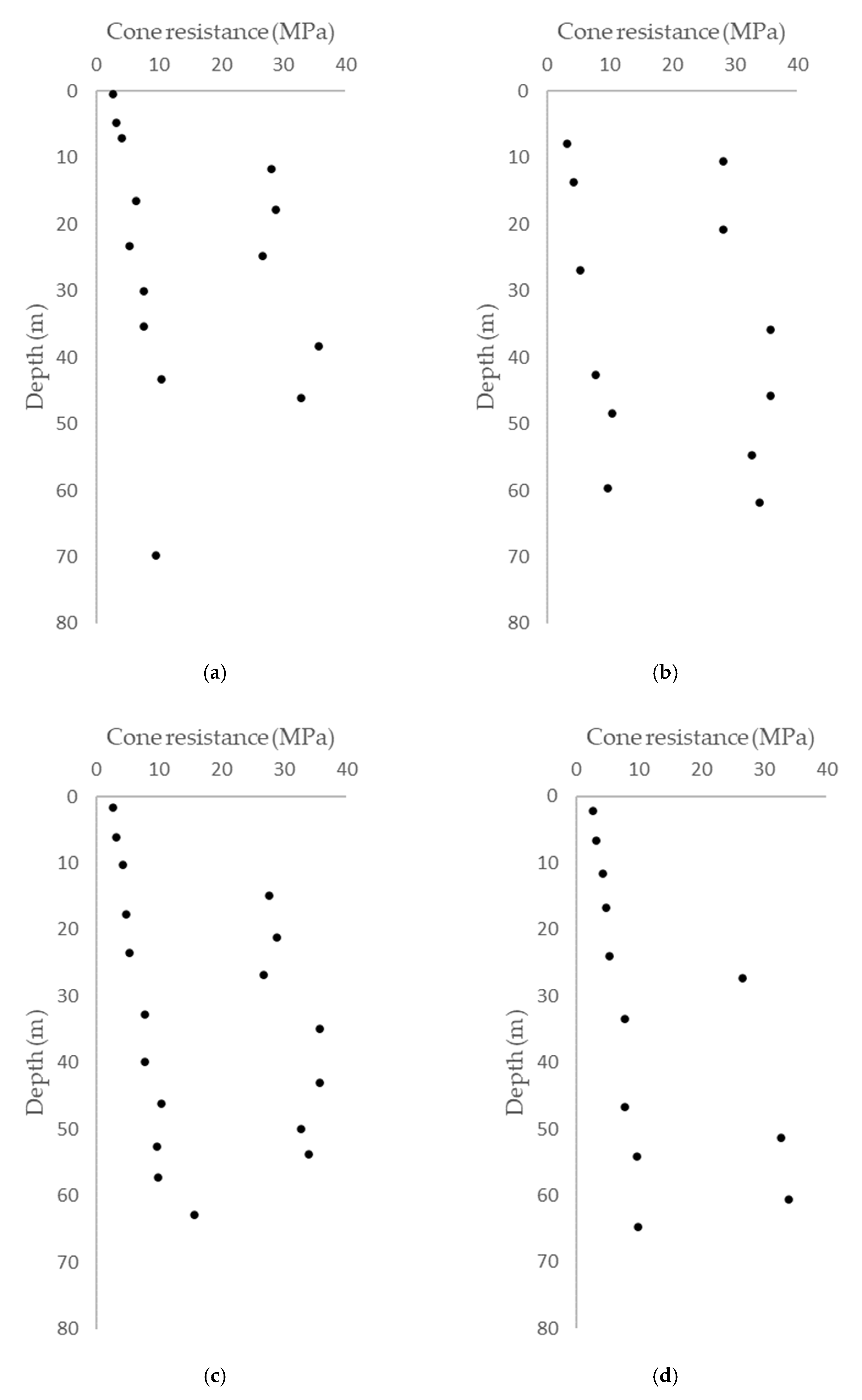
Table 1. The friction angle and cohesion strength were determined using a direct shear test with a high shearing rate, and the cone tip and shaft friction resistance were measured using a cone penetration test (see
Figure 2 for test results).
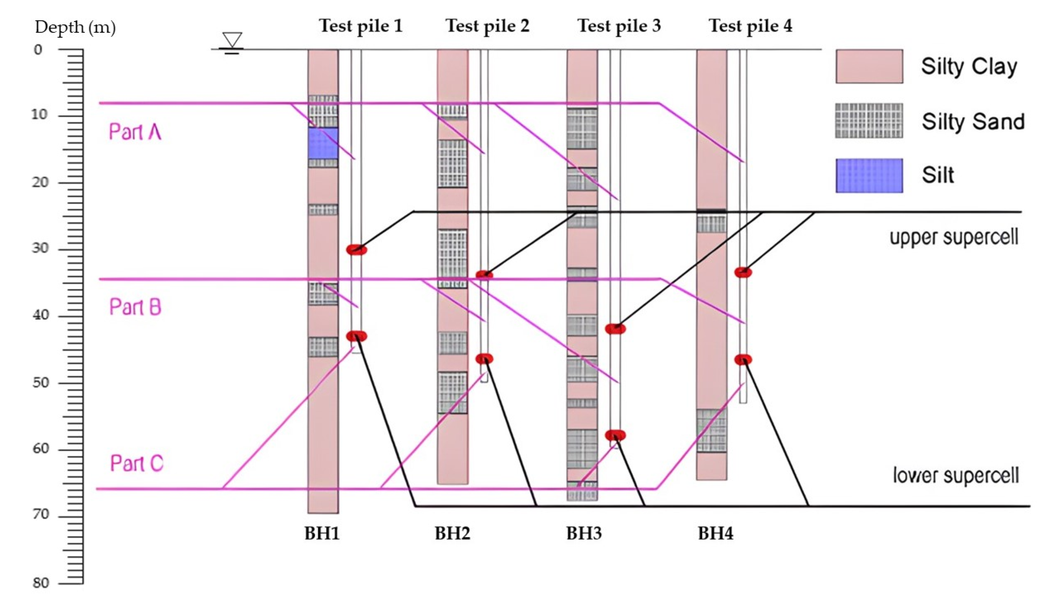
Further,
Figure 3 illustrates the subsurface conditions of four test piles based on boreholes BH1, BH2, BH3 and BH4. Meanwhile, double supercells (upper and lower supercells) were welded at the specific locations along the pile shaft and separated the test pile into Parts A, B and C.
3. Bi-Directional Static Load Test
3.1. Test Pile Description
Test Piles 1 and 3 were conducted with a 1.5-m diameter and 45.6 m and 60 m lengths, respectively. Test Piles 2 and 4 were conducted with a 1-m diameter and 50 m and 53 m lengths, respectively. To determine the loading device’s location, shaft and end bearing capacities (see
Table 2) were estimated with a semi-empirical method in terms of Local Code JGJ 94 [
10].
3.2. Loading Device Selection
Ougan Technology manufactures three types of loading devices: donut-shaped, solid and multiple supercells. As shown in
Figure 4a, the donut-shaped supercell is traditionally applicable to small piles; in
Figure 4b, the solid supercell is mostly used at the pile tip, in which the aim is to determine the end bearing; and in
Figure 4c, multiple supercells are selected in the research as its large bearing capacity.
As the single-loading device could not provide enough testing capacity for the BDSLT, this case study included two supercells that were welded onto the specific locations to separate the test pile into Parts A, B and C. Test procedure indicated that the estimated bearing capacity of Parts A, B and C should satisfy certain relationships to establish a stable reaction system for the BDSLT.
During the lower supercell’s loading, the ultimate bearing capacity of Part C was conducted, and Parts A and B worked as a reaction system for Part C. Therefore, the estimated total bearing capacity of Parts A and B should be larger than that of Part C (Q
A + Q
B > Q
C). To generate enough reaction force on Part B, the estimated bearing capacity of Part A should be larger than that of Part B (Q
A > Q
B), and to establish a proper reaction system for Part A, the grouting technology was applied to the pile tip. Base grouting significantly reinforced Part C and fully mobilised its bearing capacity. Therefore, the estimated total bearing capacity of Parts B and C should now be larger than that of post-grouted Part A (Q
B + Q
C + X > Q
A, in which X represents the improvement in pile base capacities being grouted (the end bearing capacities with full mobilisation). The length and estimated bearing capacity of each part were determined, as shown in
Table 3.
3.3. Displacement Measurement Device
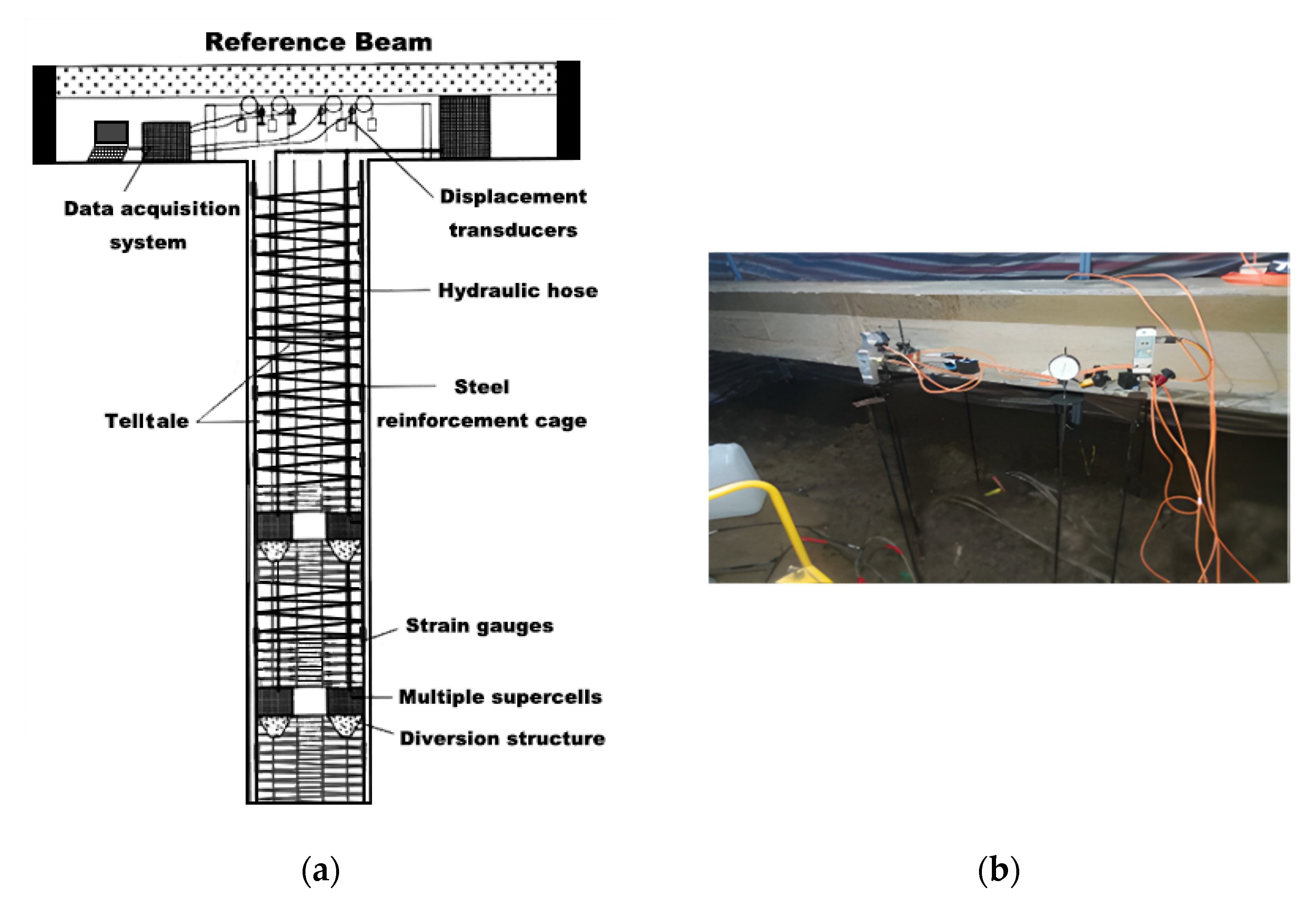
After constructing the test piles, the automated data acquisition system and multiple supercells were connected via a 32 mm telltale casing and 16 mm rod extensometer (see
Figure 5). Two sets of displacement transducers, one for the top and one for the bottom, were installed on the supercell for settlement measurement to record the upward and downward displacement, respectively. Additionally, four Linear Variable Differential Transformers (LVDTs) were mounted above the pile head on the reference beam to determine the pile head’s upside displacement (see
Figure 5), and a high-pressure pump was installed near the ground surface to apply sufficient pressure to the supercell via incompressible fluid passing through the telltale casing. An electronic manometer further measured the pressure inside the high-pressure pump, contributing to the supercell’s load measurement; this equipment is further detailed below:
Automatic data acquisition system—The digital screen and data logger controlled and collected the field test data via wired transmitters and receivers.
Telltale casing and rod extensometer—The telltale casing and rod extensometer diameters were 32 mm and 18 mm, respectively, and were embedded in the test piles.
LVDT—The measurement error had a maximum of 0.1% FS, and the resolution had a minimum of 0.01 mm. The upward and downward displacements at the supercell were measured by a group of displacement sensors, in which each group of displacement sensors comprised more than two LVDTs and was symmetrically arranged.
Multiple supercells—The loading device should be selected correctly according to pile type, testing requirements and foundation pile construction technology.
High-pressure pump—The measurement range was 0–60 MPa, and the precision was 0.4 MPa.
Figure 5.
(a) Automatic data acquisition system (b) displacement transducers on the reference beam.
Figure 5.
(a) Automatic data acquisition system (b) displacement transducers on the reference beam.
3.4. Test Setup
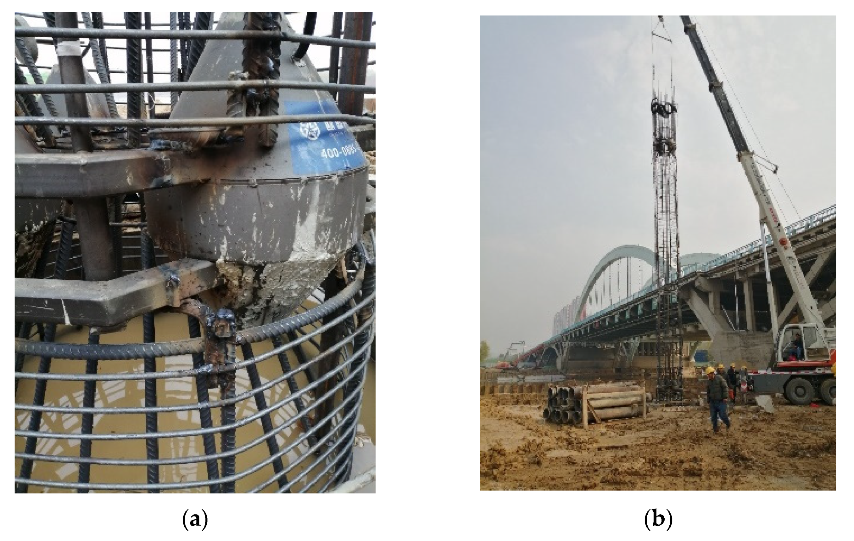
As described in the methodology, the cone-shaped multiple supercells (see
Figure 6a) were assembled on the ground surface. High-strength concrete was cast into the supercells and tamped with a concrete vibrating spear. Supercells and 1.2 m-long funnels were then welded onto the reinforced steel cage, which was manufactured with a ϕ20 steel rod with a 10 cm space. Further, the extensometer rod and hydraulic hose were tied to the steel cage, and the reinforced steel cage was then lifted into the borehole, whose eccentricity was less than five degrees (see
Figure 6b). Lastly, the concrete was cast into the borehole, and the reference beam was constructed above the pile and tied with four LVDTs (see
Figure 5).
3.5. Test Procedure
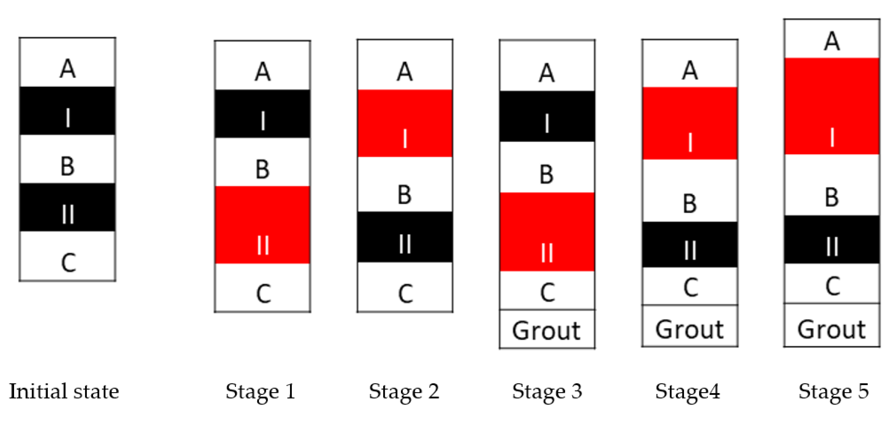
After 28 days, the BDSLT with double supercells was processed by independently loading and unloading the supercells; this BDSLT procedure was divided into five loading stages (see
Figure 7 and
Table 4): Stage 1 involved loading the lower supercell to obtain Part C’s bearing capacity, and the gap between Part B and Part C being generated; Stage 2 involved loading the upper supercell to measure Part B’s bearing capacity; Stage 3 involved loading the lower supercell at least 28 days after grouting at the pile end to measure Part C’s bearing capacity after grouting; Stage 4 included the upper supercell being loaded to remove the gap between Parts B and C; and Stage 5 involved the upper supercell’s continued loading to measure the bearing capacity of Part A after grouting.
3.6. Pile Interpretation
The BDSLT, with a single-loading device, simultaneously provided two load–settlement curves for the pile’s upper and lower segments (see
Figure 8). As different loads transform the mechanism of pile behaviour into upward and downward displacements, interpreting BDSLT is different from interpreting conventional SLT. Previous research has found a correction factor for transferring the upward friction to the downward friction [
11]. Further, the pile’s elastic shortening (
) and self-weight (
) also affected interpreted results [
11]. Considering these factors, the equivalent method provided by Local Code JT/T 738–2009 [
12] involved converting two load–settlement curves into a single curve (see
Figure 8 and Equations (1) and (2)).
Figure 8.
Q-s curve interpreted with equivalent method.
Figure 8.
Q-s curve interpreted with equivalent method.
where
is the ultimate shaft bearing capacity;
is the ultimate end bearing capacity;
is the pile’s self-weight above the supercell;
is the upward load on supercell (measured by the pressure gauge);
is the downward load on supercell;
is the pile’s equivalent transform parameter above the supercell;
is the pile’s equivalent transform parameter below the supercell (which ignores the pile’s load and displacement above supercell, );
is the equivalent displacement on the pile head corresponding to ;
is the supercell’s displacement;
is the pile’s elastic compressive deformation;
is the pile’s elastic compressive deformation below the supercell due to the supercell’s downward force;
is the pile’s elastic compressive deformation above the supercell due to the supercell’s upward force;
L is the pile’s length above the supercell;
is the pile’s elastic modulus;
is the cross-section area of the pile; and
is the soil parameter ( for clay and silt; for sand; for rock).
4. Analytical Solutions in Preliminary Design
Site investigation revealed that several analytical solutions (the semi-empirical method and the Alpha and Beta methods) were used to estimate total bearing capacity in the preliminary design, which increases construction safety. The Alpha and Beta methods were separately applied for pile shaft design in cohesive and cohesionless soils, respectively; however, unlike the Alpha and Beta methods, the semi-empirical method considered both site investigations and empirical data.
4.1. Semi-Empirical Method
Soil characteristics, pile dimensions and installation methods all influence soil–pile interface behaviours. Based on the site investigation and empirical database, the semi-empirical method was presented for the test piles’ preliminary design in accordance with local Chinese standards (Technical Code for Building Pile foundation) [
10]. As defined below, the estimated total bearing capacity (
Quk), which comprised estimated shaft and end bearing capacity, can be computed by multiplying the ultimate resistance characteristic value (
qsik and
qpk) by the bearing area. Additionally, local Chinese standards (Technical Code for Building Pile Foundation) [
10] specified the range of
qsik and
qpk, which were used in this research.
where
is the estimated shaft bearing capacity;
is the estimated end bearing capacity;
is the perimeter of the cross-section area along the pile shaft;
is the thickness of layer soil;
is the cross-section area of the pile end;
is the ultimate shaft resistance characteristic value of layer soil; and
is the ultimate bottom resistance characteristic value of layer soil.
4.2. Alpha and Beta Methods
The Alpha (α) method appropriately estimated the shaft resistance of cohesive soil by defining the adhesion factor (α), as shown below [
13]. Many existing studies have focused on the relationship between yield stress ratio and adhesion factor (α) for both displacement and non-displacement piles. Regarding non-displacement piles, Knappett and Craig (2012) [
13] proposed a piecewise function for adhesion factors based on previous research [
14,
15,
16,
17,
18]. Additionally, the Plastic Index determined the undrained shear strength over the pile’s length [
19].
where
represents the adhesion factors;
is the undrained shear strength over the pile’s length;
is the average undrained shear strength over the pile’s length;
is the cross-section area of the pile shaft; and
are the overburden pressure.
The Beta (β) method appropriately estimated the shaft resistance of cohesionless soil by the effective overburden pressure and factor β, which is determined by the coefficient of earth pressure and the interface friction angle. The testing results of the surface profile gauge revealed that pile surface roughness is much higher than particle size. Therefore, the internal friction angle obtained from the shear test can be considered the interface friction angle [
20]. Equations (9) and (10) express the Beta method:
where
K is the coefficient of earth pressure;
is the coefficient of earth pressure at rest; and
is the interface friction angle.
The end resistance of deep foundation is designed and regarded as a shallow foundation that considers the effect of soil property and foundation dimensions. Further, end bearing capacity (
Qult) was obtained by multiplying the end resistance and cross-section area of the pile end. The formula for end resistance (
qult) and end bearing capacity (
Qult) is expressed with Equations (11) and (12):
where
are the Terzaghi’s bearing capacity factors;
is the cohesion strength of soil;
is the unit weight of soil;
is the foundation’s width; and
is the cross-section area of the pile end.
5. Modified Closed-Form Analytical Solutions
The initial shear modulus (
Go or
Gmax), also known as small-strain shear modulus or low-amplitude shear modulus, is a fundamental characteristic of soil properties that can be measured using laboratory and field tests [
21,
22]; however, the plasticity index’s high value yields a significant softening of the soil, which subsequently yields a decrease in shear modulus. Compared with the operational shear modulus (
G or
GL), the initial shear modulus is limited in terms of predicting soil behaviour. Previous research has established a relationship between operational shear modulus (
G) and initial shear modulus (
Gmax) to provide an analytical solution [
23,
24,
25,
26]. Randolph and Wroth (1978) [
27] computed an elastic continuum solution in terms of operational shear modulus, in which they estimated the pile settlement in response to the anticipated loading. The basic closed-form solution developed by Randolph and Wroth [
1,
27] is expressed in Equations (13)–(15) below:
Niazi and Mayne (2014) extended this theory in reference to BDSLT (see
Table 5) and then applied the initial shear modulus to the soil stiffness reduction model in terms of the seismic cone penetration test (SCPTu) and CPTu-pile capacity correlations [
7]. In the present study, the operational shear modulus (
G or
GL) was computed with the modified closed-form analytical solutions, as informed by the load–settlement responses of Test Piles 1, 2 and 3. Due to the limitations of site investigation, the initial shear modulus (
Go) was determined using CPT cone resistance (
qc) (see Equation (16)) [
21].
where
is the applied compressive load at the pile head;
is the portion of , resisted by pile shaft;
is the upper shaft segment’s buoyant weight;
is the portion of , resisted by pile end;
is the unit shaft resistance;
is the pile shaft diameter;
is the segment’s length;
is the unit base resistance;
is the pile base diameter;
is the axial segment displacement;
is the average radius of influence in the surrounding soil mass affected by shearing stresses around the pile;
is the pile compressibility for the segment;
is the operative shear modulus;
is the modulus variation factor;
is the factor for underreamed piles that take greater loads at pile base;
is Poisson’s ratio of soil; and
is the radius of pile shaft.
The ratio for the initial shear modulus (
Go or
Gmax) and operational shear modulus (
G or
GL) is explained with the nonlinear stiffness reduction model, including Method 1 (Equation (17)) and Method 2 (Equation (18)). Method 1 uses several parameters to present the stiffness ratio (
GL/
GLmax), such as by analysing the sensitivity of pseudo-strain (
w/
d), ratio of length and diameter (
L/
d), ratio between lengths of pile shaft segments (L-ratio) and Poisson ratio of soil (
νs), which is supported by a robust database. Due to the limited data available for Method 1, it is presented here for completeness and is thus not used. Method 2 establishes the nonlinear relationship between the pseudo-strain and stiffness ratio. Compared with Method 1, Method 2 solely considers the pseudo-strain sensitivity. It determines a series of parameters (
A,
B,
C,
n), as shown in Equations (19)–(21), that predicts Test Pile 4′s load–settlement response.
6. Results and Discussion
6.1. Pile Interpretation
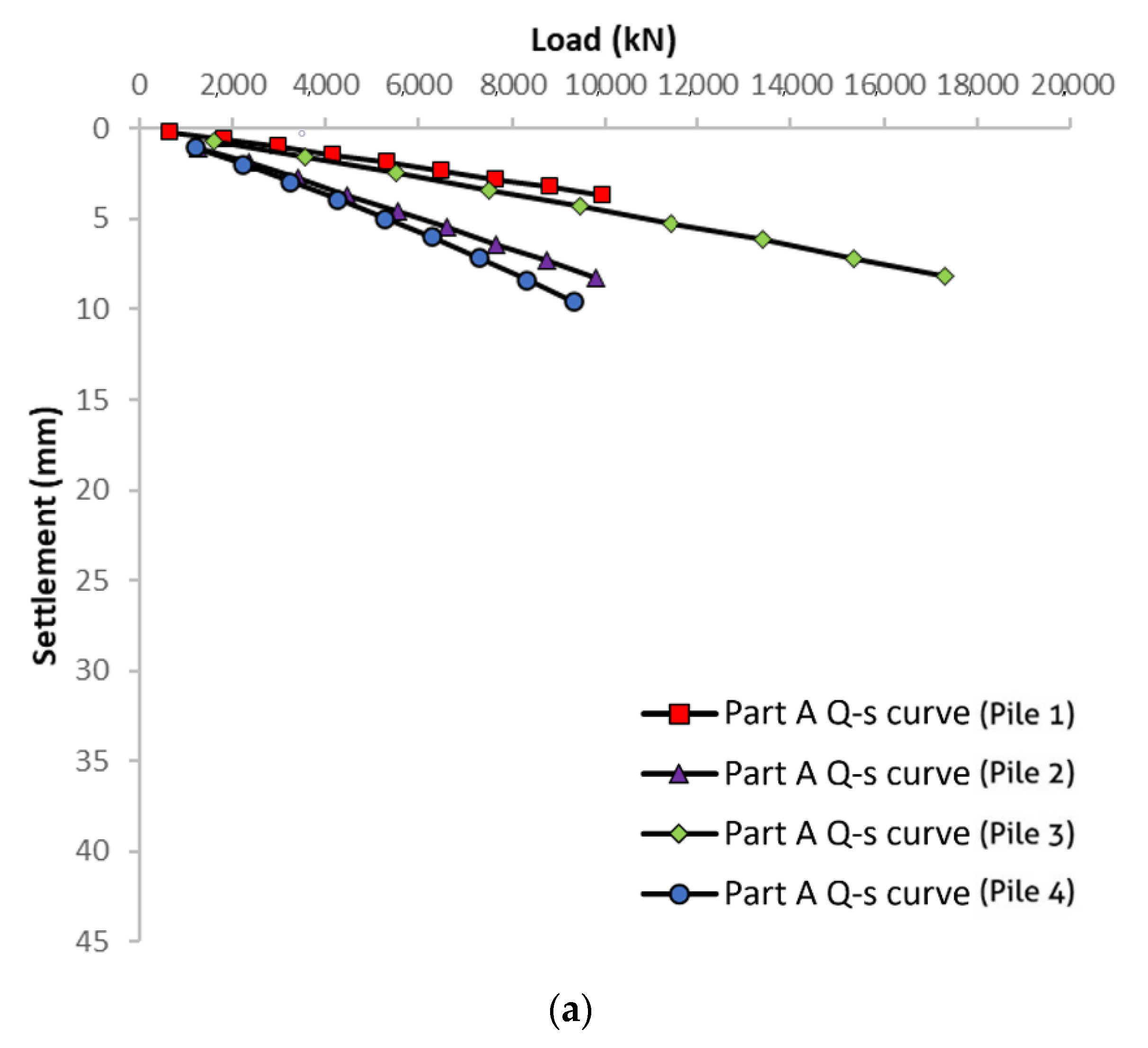
Considering the pile’s self-weight and negative friction, the load–settlement response of the upper part (Part A) is interpreted. It displays a linear relationship in load–settlement response, and the settlement is considerably lower than the 40 mm criterion. Therefore, according to conventional requirements, the bearing resistance does not reach the failure load [
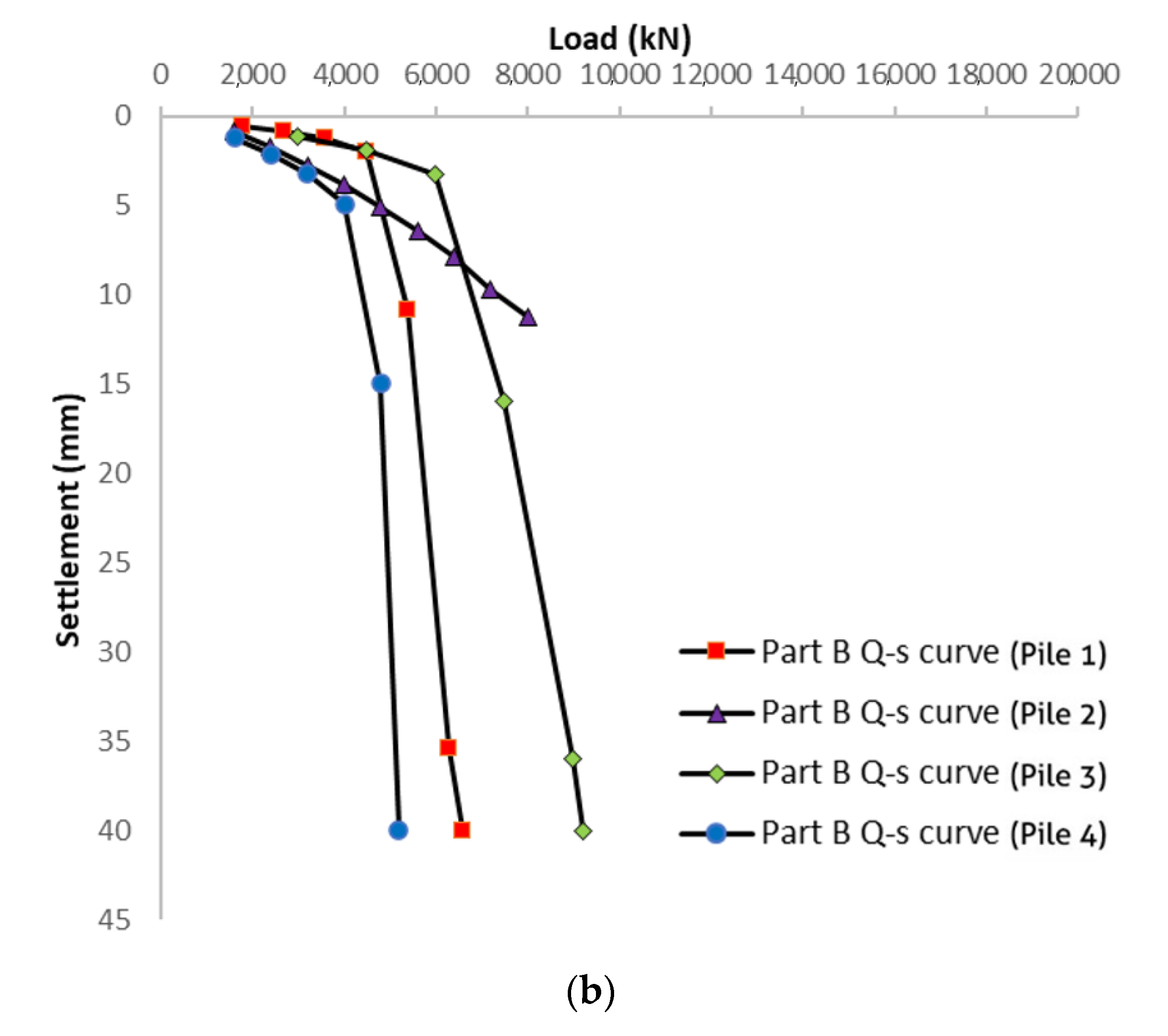
28]. Regarding the middle part (Part B), most of the interpreted load–settlement responses displayed a significant reduction (this stage’s settlement change is over five times the former stage) at the failure load (see
Figure 9b). Since the middle parts of Test Piles 2 and 4 had similar dimensions and overburden pressures, the increment of sand layer thickness significantly improved bearing capacity.
Overall, this case study indicates that pile settlement and diameter ratios of about 1% and 4% are expected to fully mobilise the pile shaft and base resistances, respectively. These observations align with those made by Al-Atroush et al. (2020) and Ong (2005) [
29,
30] and further justify the acceptance of the criteria adopted, in which the maximum pile settlements are limited to less than 40 mm; this effectively translates to 2.6% and 4% of the pile with diameters of 1.5 m (Piles 1 and 3) and 1 m (Piles 2 and 4), respectively.
The site investigation results reveal that the soft underlying stratum exists in most test piles, which might not satisfy the BDSLT reaction system’s requirements (see
Section 3.2). Previous research has found that bored pile post-grouting technology significantly improves the end bearing capacity and reduces the settlement [
31,
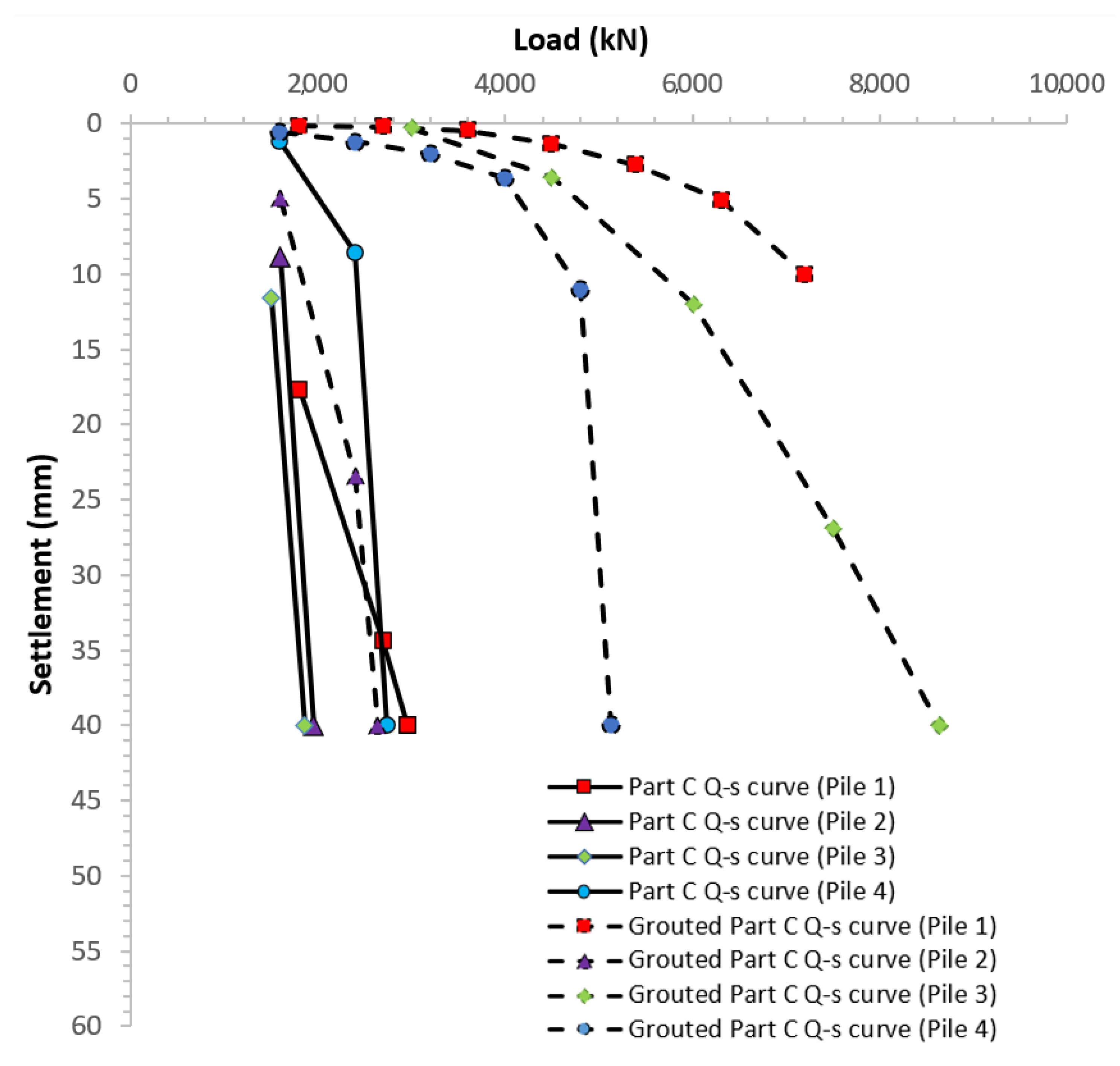
32]. Therefore, grouting technology is required to fully mobilise the end bearing capacity of the lower part (Part C). The testing result indicates great improvements after grouting at the pile end (see
Table 6 and
Figure 10). Compared with the clay-bearing stratum, the sand-bearing stratum with a higher level of hydraulic conductivity provides a better grouting improvement. Further, the higher overburden pressure yields a more considerable grouting improvement (see Test Piles 1 and 3 in
Table 5).
6.2. Conventional Analytical Solutions
Two kinds of estimated bearing capacities were obtained in the preliminary design through the semi-empirical method and the Alpha and Beta methods (see
Table 7). The predicted bearing capacity obtained from the latter two is not precise enough without considering the effect of polymer suspension. Polymer mixed with water stabilises the borehole during pile construction and affects the full mobilisation of pile resistance. Interface characteristics along the pile shaft are thus significantly influenced. Conversely, compared with the interpreted ultimate bearing capacity, the semi-empirical method provided an estimated shaft bearing capacity with higher fitness, as it considered pile surface roughness and soil stiffness; however, the relationship between shaft resistance and interface parameters was ambiguous. Therefore, establishing an algorithm is crucial, as is quantitatively analysing pile behaviour in the preliminary design.
6.3. Analytical Solution of the Randolph Method
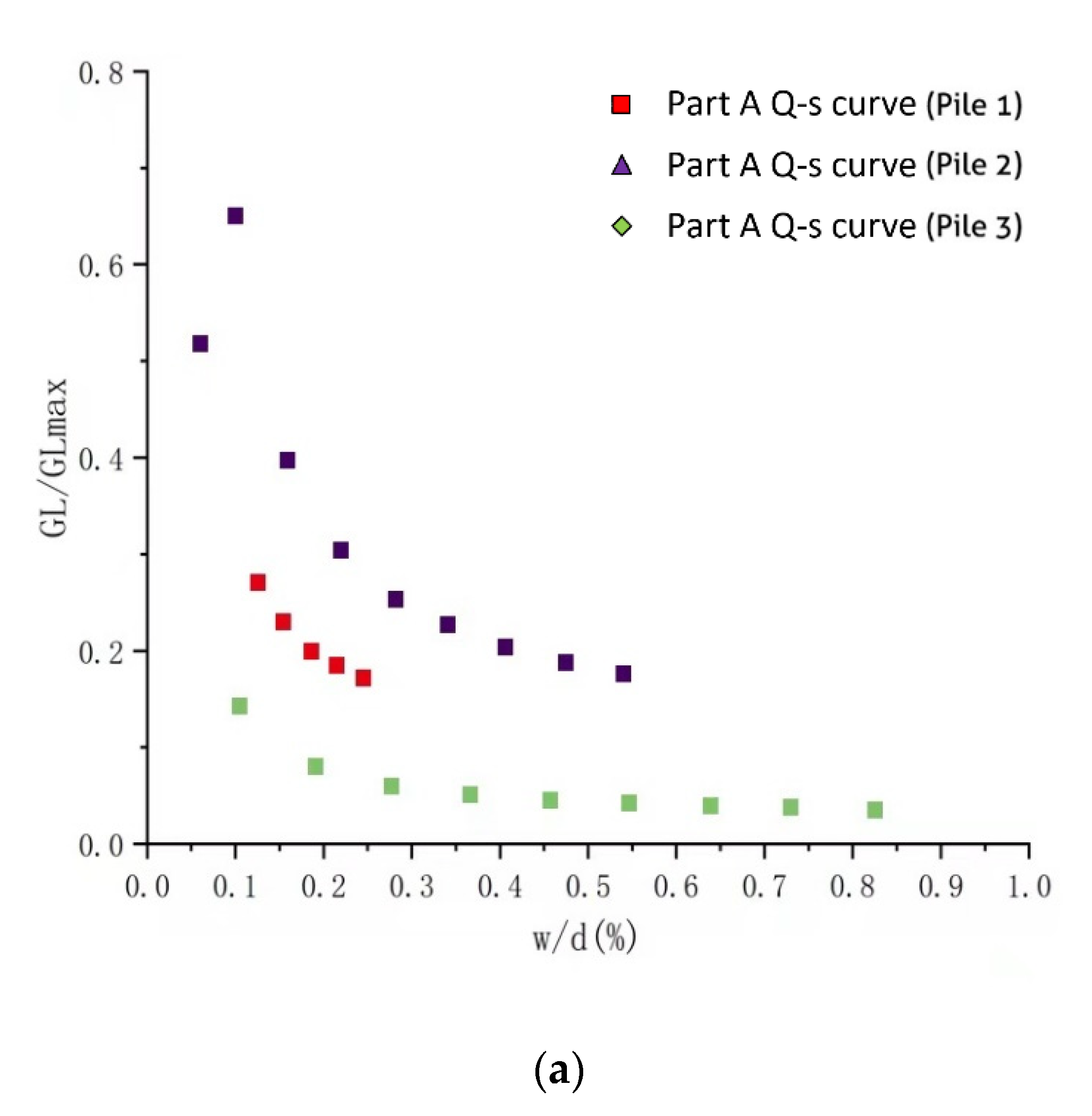
According to the load–settlement responses of the test piles and site investigation outcomes, the operational shear modulus of test piles was determined using modified closed-form analytical solutions. The modulus reduction factor (
GL/
GLmax) versus percent pseudo-strain (
w/
d [%]) demonstrated a nonlinear relationship (see
Figure 11). The modulus reduction factors reduced in proportion to the increase in segment displacement, and a higher sand stratum thickness yielded a greater modulus reduction factor for upper pile segments (see
Figure 3 and
Figure 11a). In contrast, the expected behaviours of the lower and middle segments provided outcomes with a high level of fitness, which might be due to the beneficial use of polymer slurry.
Further, the factors (
A,
B,
C,
n) of the nonlinear stiffness reduction model were deducted with curve fitting and then back-analysed within Test Piles 1, 2 and 3. By applying these factors to Equation (18), Equations (19)–(21) were obtained:
The operational shear modulus of Test Pile 4 was determined according to the curve-fitting results of the nonlinear stiffness reduction model (Equations (19)–(21)), and then the load–settlement response (see
Figure 12) was predicted as informed by the modified closed-form analytical solutions. The result indicates a high fitness between the interpreted and predicted load–settlement response. For the middle and lower parts, ultimate bearing capacity was exactly predicted, and analytical solutions led to overestimated results with large settlement (>60 mm); however, due to the dispersed data of the test pile’s upper part (see
Figure 11a), the predicted load–settlement response might not be reliable; this indicates that further investigation is required.
7. Conclusions and Recommendations
This article explored long-drilled pile behaviour in response to BDSLTs, and it validates theoretical research based on pile interpretation and analytical solutions. With two loading supercells welded to the single test pile, the BDSLT is thus more beneficial than just a conventional single-loading device in terms of providing more reliable test data. The load–settlement response obtained was interpreted with consideration of the negative friction effect and the pile’s elastic deformation and self-weight, which contributes to greater accuracy. The interpreted results indicate that the sand stratum provides more resistance than the clay stratum, and that grouting improvement is significant in the sand stratum. Therefore, construction project site selection conducted in sand stratum will contribute to higher pile resistance and better grouting improvement. Ultimately, the base grouting effect is more beneficial for controlling pile settlement than increasing the working pile base capacity, especially when long friction-dominant piles are constructed in high ground water that might create ‘soft toe’ issues. Base grouting can solve these soft toe issues by enabling improved pile and rock contact.
However, as the preliminary design’s analytical solutions are based on assumed factors and the availability of empirical data, their prediction accuracy is not reliable, especially if the Alpha and Beta methods are used. Additionally, the polymer applied for wet construction will affect the pile resistance, which might also contribute to decreased reliability; however, when the modified closed-form analytical solutions and interpreted load–settlement response are implemented carefully while considering all noted influencing factors, especially when the behaviour of soil stiffness is corrected, predicting the capacity of long bored pile foundations could be accomplished more accurately. Using the BDSLT also reduces the pile load testing time, as the supercells can be easily and reliably incorporated into the pile body during construction. BDSLT also ensures construction safety, as a large kentledge set-up can be avoided, especially if the pile load tests are conducted on soft grounds.
Author Contributions
Conceptualization, R.W. and D.E.L.O.; methodology, R.W., D.E.L.O. and J.Z.; software, R.W.; validation, R.W.; formal analysis, R.W. and S.L.; investigation, R.W. and S.L.; resources, S.L.; data curation, R.W.; writing—original draft preparation, R.W., D.E.L.O. and J.Z.; writing—review and editing, R.W., D.E.L.O. and J.Z.; visualization, R.W. and E.O.; supervision, D.E.L.O. and E.O.; project administration, D.E.L.O., S.L. and E.O.; funding acquisition, D.E.L.O. All authors have read and agreed to the published version of the manuscript.
Funding
This research received no external funding.
Institutional Review Board Statement
Not applicable.
Informed Consent Statement
Not applicable.
Data Availability Statement
The original experimental data are available on request from the corresponding author.
Conflicts of Interest
The authors declare no conflict of interest.
References
- Randolph, M.F.; Wroth, C.A. Simple approach to pile design and the evaluation of pile tests. In Behavior of Deep Foundations; Lundgren, R., Ed.; ASTM International: Philadelphia, PA, USA, 1979; p. 484. [Google Scholar] [CrossRef]
- Osterberg, J. New device for load testing driven piles and drilled shafts separates friction and end. In Piling and Deep Foundations, Proceedings of the International Conference on Piling and Deep Foundations; Burland, J., Mitchell, J., Eds.; CRC Press: London, UK, 1989; Volume 1, p. 421. [Google Scholar]
- Choi, Y.; Lee, M.H.; Nam, M.S.; Kim, T.H.; Stuedlein, A.W. Development and implementation of a high-pressure, double-acting, bi-directional loading cell for drilled shafts. Geotech. Test J. 2016, 39, 196–205. [Google Scholar] [CrossRef]
- Hayes, J. The landmark Osterberg cell test. Deep Found. 2012, 45–49. [Google Scholar]
- Zheng, Y.J.; Dai, X.; Li, L.X. Analysis of an O-cell pile test in Jinan with FEM. Appl. Mech. Mater. 2012, 170–173, 33–36. [Google Scholar] [CrossRef]
- Baca, M.; Rybak, J. Pile base and shaft capacity under various types of loading. Appl. Sci. 2021, 11, 3396. [Google Scholar] [CrossRef]
- Niazi, F.S.; Mayne, P.W. Axial pile response of bidirectional O-cell loading from modified analytical elastic solution and downhole shear wave velocity. Can. Geotech. J. 2014, 51, 1284–1302. [Google Scholar] [CrossRef]
- Baca, M.; Brząkała, W.; Rybak, J. Bi-directional static load tests of pile models. Appl. Sci. 2020, 10, 5492. [Google Scholar] [CrossRef]
- Baca, M.; Brzakala, W. Numerical modeling of pile installation influence on surrounding soil. In Proceedings of the International Multidisciplinary Scientific GeoConference: SGEM, Sofia, Bulgaria, 29 June—5 July 2017; Volume 17, pp. 619–626. [Google Scholar] [CrossRef]
- JGJ94–2008; Technical Code for Building Pile Foundations. Ministry of Housing and Urban–Rural Development of the People’s Republic of China: Beijing, China, 2008. (In Chinese)
- Dai, G.; Gong, W. Application of bi-directional static loading test to deep foundations. J. Rock Mech. Geotech. Eng. 2012, 4, 269–275. [Google Scholar] [CrossRef]
- JT/T 738–2009; Static Loading Test of Foundation Pile—Self-Balanced Method. Ministry of Transport of the People’s Republic of China: Beijing, China, 2009. (In Chinese)
- Knappett, J.; Craig, R.F. Craig’s Soil Mechanics, 9th ed.; CRC Press: London, UK, 2019. [Google Scholar] [CrossRef]
- Karlsrud, K.; Hansen, S.; Dyvik, R.; Kalsnes, B. NGI’s pile tests at Tilbrook and Pentre—Review of testing procedures and results. In Large-Scale Pile Tests in Clay; Thomas Telford Publishing: London, UK, 1993; pp. 405–429. [Google Scholar]
- Semple, R.M.; Rigden, W.J. Shaft capacity of driven pipe piles in clay. In Analysis and Design of Pile Foundations; ASCE: Reston, VA, USA, 1984; pp. 59–79. [Google Scholar]
- Skempton, A.W. Cast in-situ bored piles in London clay. Geotechnique 1959, 9, 153–173. [Google Scholar] [CrossRef]
- Stas, C.V.; Kulhawy, F.H. Critical Evaluation of Design Methods for Foundations under Axial Uplift and Compression Loading; Electric Power Research Institute: New York, NY, USA, 1983; Volume 3771. [Google Scholar]
- Weltman, A.; Healy, P. Piling in boulder clay and other glacial tills. DOE and CIRIA Piling Development Group report PG5. Int. J. Rock Mech. Min. Sci. 1978, 16. [Google Scholar] [CrossRef]
- Skempton, A.W. The post-glacial clays of Thames estuary at Tilbury and Shell-Haven. In Proceedings of the 3rd International Conference on Soil Mechanics and Foundation Engineering; ICOSOMEF: Zurich, Switzerland, 1953; Volume 1, pp. 302–308. [Google Scholar]
- Wang, R.; Ong, D.E.L.; Peerun, M.I.; Jeng, D.S. Influence of surface roughness and particle characteristics on soil–structure interactions: A state-of-the-art review. Geosciences 2022, 12, 145. [Google Scholar] [CrossRef]
- Anagnostopoulos, A.; Koukis, G.; Sabatakakis, N.; Tsiambaos, G. Empirical correlations of soil parameters based on cone penetration tests (CPT) for Greek soils. Geotech. Geol. Eng. 2003, 21, 377–387. [Google Scholar] [CrossRef]
- Elbeggo, D.; Éthier, Y.; Karray, M.; Dubé, J.S. Valeurs de la Vitesse de Propagation des Ondes de Cisaillement dans les Argiles de la Mer de Champlain au Canada Predates par des Corrélations Empiriques. In Proceedings of the GeoMontreal Conference, Mont Tremblant, QC, Canada, 3–6 October 2013. [Google Scholar]
- Amir-Faryar, B.; Aggour, M.S.; McCuen, R.H. Universal model forms for predicting the shear modulus and material damping of soils. Geomech. Geoengin. 2017, 12, 60–71. [Google Scholar] [CrossRef]
- Ishibashi, I.; Zhang, X. Unified dynamic shear moduli and damping ratios of sand and clay. Soils Found. 1993, 33, 182–191. [Google Scholar] [CrossRef]
- Kallioglou, P.; Tika, T.; Pitilakis, K. Shear modulus and damping ratio of cohesive soils. J. Earthq. Eng. 2008, 12, 879–913. [Google Scholar] [CrossRef]
- Vardanega, P.J.; Bolton, M.D. Stiffness of clays and silts: Normalizing shear modulus and shear strain. J. Geotech. Geoenviron. Eng. 2013, 139, 1575–1589. [Google Scholar] [CrossRef]
- Randolph, M.F.; Wroth, C.P. Analysis of deformation of vertically loaded piles. J. Geotech. Geoenviron. Eng. 1978, 104, 1465–1488. [Google Scholar] [CrossRef]
- JGJ/T 403–2017; Technical Specification for Static Loading Test of Self-Balanced Method of Building Foundation Piles. Ministry of Housing and Urban–Rural Development of the People’s Republic of China: Beijing, China, 2017. (In Chinese)
- Al-Atroush, M.E.; Hefny, A.; Zaghloul, Y.; Sorour, T. Behavior of a large diameter bored pile in drained and undrained conditions: Comparative analysis. Geosciences 2020, 10, 261. [Google Scholar] [CrossRef]
- Ong, D.E.L. Pile Behaviour Subject to Excavation-Induced Soil Movement in Clay. Ph.D. Thesis, National University of Singapore, Singapore, 21 April 2005. [Google Scholar]
- Zhao, F. Mechanism research on the improvement of bearing capacity of single pile by pile-base post grouting technique and estimation of bearing capacity. MATEC Web Conf. 2015, 25, 03008. [Google Scholar] [CrossRef][Green Version]
- Bagui, S.K.; Puri, S.K.; Rao, V.; Dinesh, B.C.; Das, A. Estimation of base grout quantity for cast in situ piles based on field test results. Adv. Bridge Eng. 2020, 1, 4. [Google Scholar] [CrossRef]
Figure 1.
Test pile location (in scale).
Figure 1.
Test pile location (in scale).
Figure 2.
Cone penetration test results for (a) Test Pile 1, (b) Test Pile 2, (c) Test Pile 3 and (d) Test Pile 4.
Figure 2.
Cone penetration test results for (a) Test Pile 1, (b) Test Pile 2, (c) Test Pile 3 and (d) Test Pile 4.
Figure 3.
Subsurface conditions along test piles.
Figure 3.
Subsurface conditions along test piles.
Figure 4.
Supercell products: (a) donut-shaped supercell, (b) solid supercell and (c) multiple supercells.
Figure 4.
Supercell products: (a) donut-shaped supercell, (b) solid supercell and (c) multiple supercells.
Figure 6.
Installation of (a) supercell and (b) reinforcement cage.
Figure 6.
Installation of (a) supercell and (b) reinforcement cage.
Figure 7.
Locations of double supercells installed, separating the piles in Parts A, B and C (supercells are marked as red).
Figure 7.
Locations of double supercells installed, separating the piles in Parts A, B and C (supercells are marked as red).
Figure 9.
Interpreted load–settlement response of (a) upper part (Part A) (b) middle part (Part B).
Figure 9.
Interpreted load–settlement response of (a) upper part (Part A) (b) middle part (Part B).
Figure 10.
Interpreted load–settlement response of lower part (Part C).
Figure 10.
Interpreted load–settlement response of lower part (Part C).
Figure 11.
Modulus reduction factor (GL/GLmax) versus per cent pseudo-strain (w/d [%]) for (a) upper part, (b) middle part and (c) lower part.
Figure 11.
Modulus reduction factor (GL/GLmax) versus per cent pseudo-strain (w/d [%]) for (a) upper part, (b) middle part and (c) lower part.
Figure 12.
Predicted load–settlement responses based on modified closed-form analytical solutions for (a) upper part, (b) middle part and (c) lower part.
Figure 12.
Predicted load–settlement responses based on modified closed-form analytical solutions for (a) upper part, (b) middle part and (c) lower part.
Table 1.
Parameters of three typical soils.
Table 1.
Parameters of three typical soils.
| Soil Type | Unit Weight | Friction Angle | Cohesive Strength | Cone Tip Resistance | Shaft Friction Resistance | Unconfined Compressive Strength | Compression Modulus | Poisson’s Ratio |
|---|
| | c | | | | E | ν |
|---|
| Unit | | degrees | kPa | MPa | kPa | kPa | MPa | |
| Silty sand | 19.0 | 28 | 0 | 23.8 | 386.3 | N/A | 26.55 | 0.3 |
| Silt | 19.6 | 27.53 | 8.65 | 8.0 | 160.1 | 39 | 6.38 | 0.3 |
| Silty clay | 19.3 | 15.20 | 43.80 | 8.4 | 261.0 | 73 | 6.91 | 0.3 |
Table 2.
Dimensions and estimated bearing capacity of test piles.
Table 2.
Dimensions and estimated bearing capacity of test piles.
| Test Pile Code | Related Borehole | Pile Length
(m) | Pile Diameter
(m) | End Bearing Capacity
(kN) | Shaft Bearing Capacity
(kN) |
|---|
| 1 | BH1 | 45.6 | 1.5 | 3004.15 | 17,301.63 |
| 2 | BH2 | 50 | 1.0 | 1335.18 | 12,543.75 |
| 3 | BH3 | 60 | 1.5 | 3004.15 | 21,618.18 |
| 4 | BH4 | 53 | 1.0 | 1335.18 | 15,580.41 |
Table 3.
Test pile length and estimated bearing capacity.
Table 3.
Test pile length and estimated bearing capacity.
| Test Pile Code | Part A | Part B | Part C |
|---|
Length
(m) | Bearing Capacity
(kN) | Length
(m) | Bearing Capacity
(kN) | Length
(m) | Bearing Capacity
(kN) |
|---|
| 1 | 30.1 | 11,851.09 | 13 | 5157.24 | 2.5 | 3865.20 |
| 2 | 34.0 | 8563.23 | 12.5 | 3090.32 | 3.5 | 2225.38 |
| 3 | 42.0 | 15,735.61 | 16 | 5617.92 | 2.0 | 3268.80 |
| 4 | 33.5 | 9090.51 | 13 | 3593.98 | 6.5 | 2895.92 |
Table 4.
Procedure and purposes of the BDSLTs.
Table 4.
Procedure and purposes of the BDSLTs.
| | Loading State | Purposes |
|---|
| Upper Supercell | Lower Supercell |
|---|
| Stage 1 | Maintain | Loading | Bearing capacity of Part C (before grouting; possibly with ‘soft toe’ issues) |
| Stage 2 | Loading | Unloading | Bearing capacity of Part B |
| Stage 3 | Maintain | Loading | Bearing capacity of Part C (after grouting) |
| Stage 4 | Loading | Unloading | Removing the gap between Parts B and C |
| Stage 5 | Loading | Maintain | Bearing capacity of Part A |
Table 5.
Modified closed-form analytical solutions for two cases of O-cell pile loading.
Table 5.
Modified closed-form analytical solutions for two cases of O-cell pile loading.
| | Related Formula |
|---|
| Total pile load | |
| Upper shaft response | |
| Middle shaft response | |
| Lower shaft response | |
Table 6.
Interpreted end bearing capacities of test piles.
Table 6.
Interpreted end bearing capacities of test piles.
| Pile No. | Pile Length
(m) | Bearing Stratum of Part C | End Bearing Capacity (kN) | Improved Rate |
|---|
| Before Grouting | After Grouting |
|---|
| 1 | 45.6 | Sand | 2959 | 8100 | 173.7% |
| 2 | 50 | Sand, clay | 1600 | 2636 | 64.8% |
| 3 | 60 | Sand | 1857 | 7500 | 303.9% |
| 4 | 53 | Clay | 2741 | 4800 | 75.1% |
Table 7.
Estimated and interpreted results with test piles.
Table 7.
Estimated and interpreted results with test piles.
| No. | Type of Theoretical Determination | Qs (Part A)
kN | Qs (Part B)
kN | Qs + Qb (Part C)
kN |
|---|
| 1 | Semi-empirical method | 11,283.34 | 5157.24 | 3865.20 |
| Alpha method and Beta method | 2988.03 | 2959.35 | 9849.99 |
| Supercell test result | >9965 | 4500 | 2959 |
| 2 | Semi-empirical method | 8563.23 | 3090.32 | 2225.38 |
| Alpha method and Beta method | 3975.08 | 3199.18 | 2522.05 |
| Supercell test result | >9798 | >8000 | 1956 |
| 3 | Semi-empirical method | 15,735.61 | 5617.92 | 3268.80 |
| Alpha method and Beta method | 8332.52 | 6600.02 | 15,715.64 |
| Supercell test result | >17316 | 6000 | 1857 |
| 4 | Semi-empirical method | 9090.51 | 3593.98 | 4231.10 |
| Alpha method and Beta method | 2985.57 | 2135.71 | 3826.58 |
| Randolph method | >8665 | 4196 | 2400 |
| Supercell test result | >9329 | 4000 | 2400 |
| Publisher’s Note: MDPI stays neutral with regard to jurisdictional claims in published maps and institutional affiliations. |
© 2022 by the authors. Licensee MDPI, Basel, Switzerland. This article is an open access article distributed under the terms and conditions of the Creative Commons Attribution (CC BY) license (https://creativecommons.org/licenses/by/4.0/).
