Abstract
Road subsidence and sinkhole failures due to shallow cavities formed by defective water main have increased in recent decades and become one of the important research topics in geotechnical engineering. The present paper numerically studies the stability and its associated failure mechanism of ellipse-shaped cavity above defective water mains using the finite element limit analysis technique. For a wide range of geometrical parameters, the pressure ratio method is used to formulate the stability solutions in both blowout and collapse scenarios. Even though there is no published solution for elliptical cavities under blowout failure conditions, the obtained numerical results are compared with available circular solutions. Several conclusions are drawn based on the failure mechanism study of the various ellipse shape transformations in this study, whilst design charts and equations proposed for practical uses.
1. Introduction
Natural and human-induced sinkholes are the two main categories of sinkholes that can be instantaneous and catastrophic. The human-induced sinkhole events are speedily increasing in recent decades, and they are the news headline of most national and international media [1]. Sinkholes are a significant hazard in many areas worldwide and are studied scientifically by [2,3,4]. The recent increase in sinkhole events due to water main defects necessitates the problem to be better understood, predicted and prevented. The water main damage-driven sinkhole is a significant concern in many metropolises across the globe. Several factors such as maintenance lack, water pressure increased, differential settlement, root damage and corrosion are responsible for causing the water main damage [1]. Table 1 presents some of the latest sinkhole events that occur across the globe [5,6,7,8].
Table 1.
Examples of recent sinkhole events induced by water mains defect.
The trapdoor problem is a classical geotechnical stability example for the pipe leakage-driven cavities. Collapse failure (downward movement) and blowout failure (upward movement) are the two main modes of trapdoor failures. The self-weight of soil mass and ground surcharge pressures are two critical components associated to collapse failures, whereas blowout failures are only due to external forces, such as the water main pressure, exerted against the soil weight and ground surcharge. There have been numerous studies concerning “collapse” and “blowout” stability, though much of them are limited to a flat planar trapdoor [9].
Flat planar trapdoor stability under active plain strain conditions was investigated by Sloan et al. [10,11,12,13,14,15,16,17,18]. Note that these previous works are limited to the “collapse” stability problems. Recently, pipe burst-related ground stability in “blowout” stability above a damaged water main pipeline under three idealized stages of internal soil erosion was studied by Shiau et al. [19]. Other studies about stability of sinkholes through modelling have been proposed in the literature (e.g., [20,21,22,23]).
To the authors’ best knowledge, very few studies were reported on the stability effects of elliptical cavity shape transformation, especially for the “blowout” stability problems. Dutta and Bhattacharya [24] studied the stability of dual elliptical tunnels in soft clay using lower bound finite element limit analysis with second-order conic programming. Yang et al. [25] investigated the effects of surcharge loading on an elliptical tunnel using the upper-bound finite element method with rigid translatory moving elements in cohesive-frictional soils. Zhang et al. [26] analyzed the stability of elliptical tunnels in cohesionless soils using the upper bound solution approach. Moreover, the stability analysis of unlined elliptical tunnel using finite element upper-bound method with plastic deformation element method was studied [27,28].
The presence of a soil cavity due to subsurface soil erosion can cause a sinkhole. Interestingly, most sinkhole formations are circular at the ground surface [2,3,4,20,21,22,23,29,30]. Figure 1 presents the potential stages of water main related soil failures. The passive (blowout) and active (collapse) failures are based on the limit loads acting on the sinkhole’s upward and downward orientations, respectively. Despite the uncertainty of the shape transformation, it has been found that most of the previous research were centered on the fundamental trapdoor shape transformation, i.e., circular, square and rectangle [31]. Very few studies were performed on elliptical shape transformation. Furthermore, there has also been a lack of research in relation to sinkhole stability above the pressurized drinking water mains, although sinkhole events are often seen on main roads worldwide.
Figure 1.
Various stages of watermain related soil failures.
This paper applies advanced finite element limit analysis (FELA) and adaptive mesh techniques to study sinkhole stability due to defective water mains. It is noted that low pressure in the pipe leads to dragging the loose soil particle into the sewer pipe through the crack in the pipe, creating a cavity in the soil. In contrast, high water pressure is accountable for blowout failure. It is therefore hypothesized that the initiation of a cavity is caused by a fracture in the pipe, which leads to ultimate failure in one of two scenarios: blowout or collapse. Elliptical cavity shapes transformation is studied for a wide range of depth ratios, ellipse width to height ratios and soil shear strength ratios. Design charts and equations are presented for practical uses in the preliminary stability assessment under both collapse and blowout scenarios.
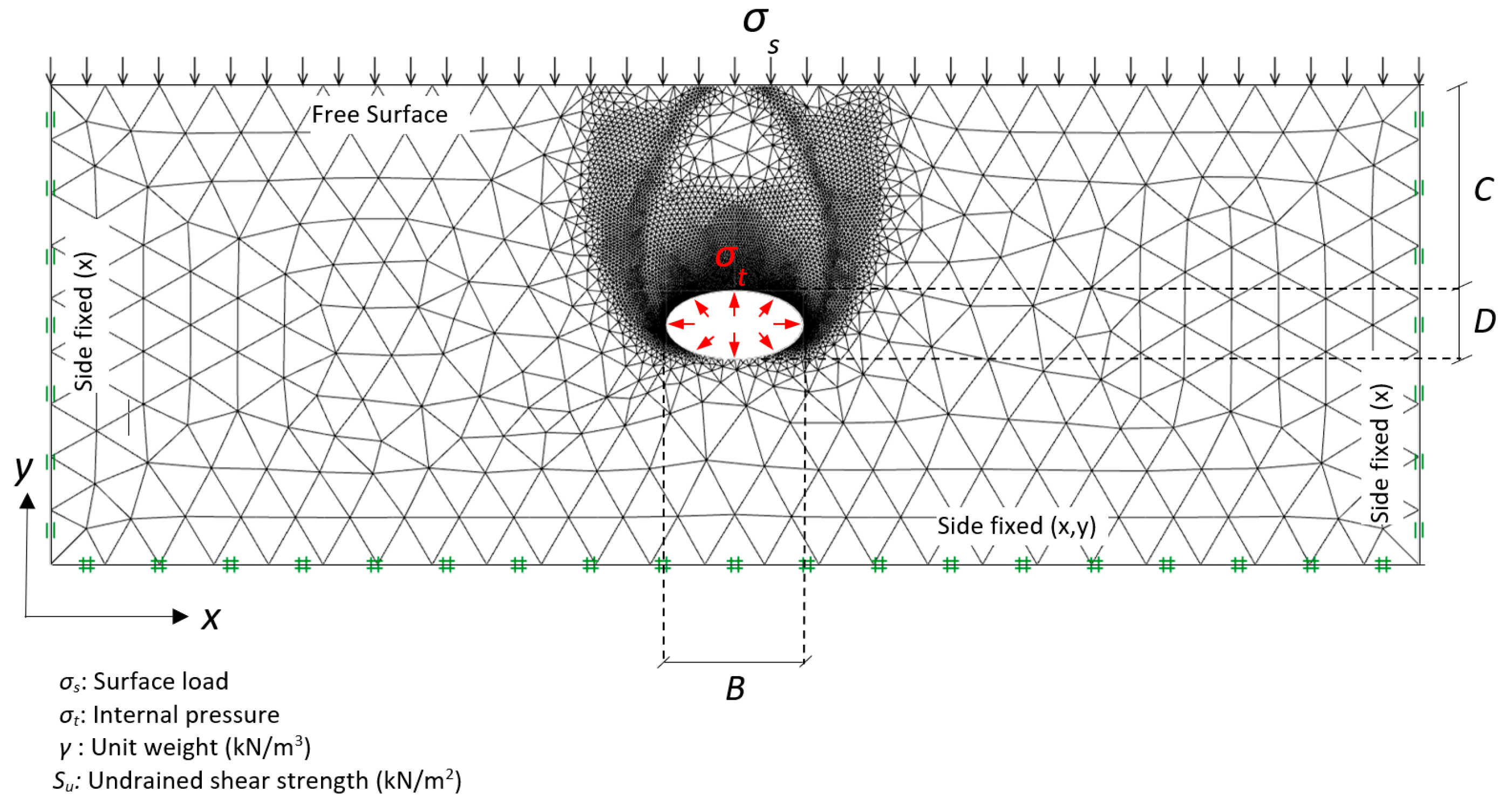
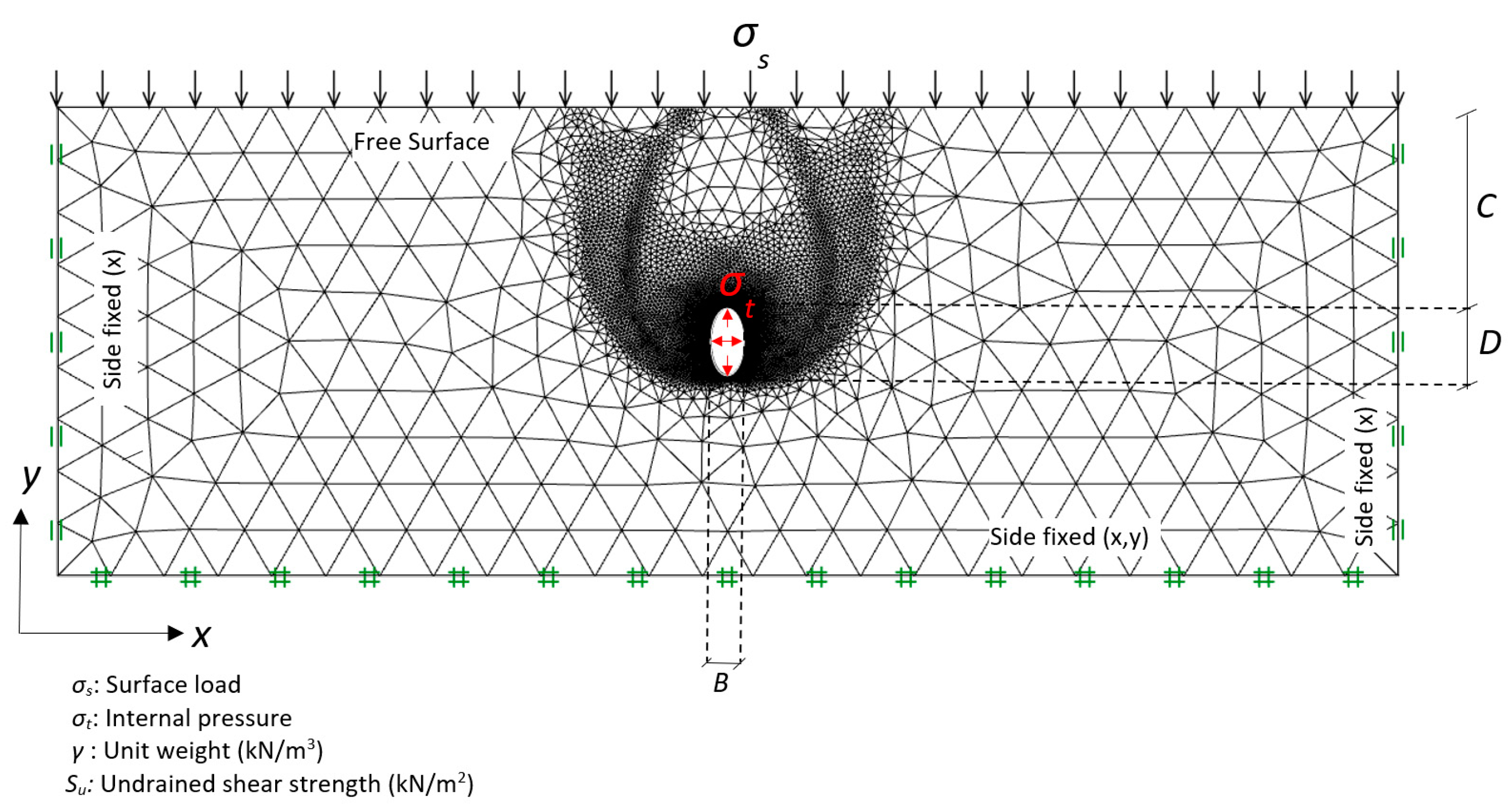
2. Problem Definition and FELA Model
An idealized cavity shape is assumed following Equation (1), which describes the shape of an ellipse.
where a = B/2, b = D/2 and x and y are coordinates of an ellipse. Using Equation (1), a typical adaptive FELA mesh is shown in Figure 2 for a width to height ratio B/D = 2, whilst in Figure 3 for width to height ratio B/D = 0.5. In both cases, the trapdoors have a cover (C), depth (D) and width (B). The inner perimeter of the opening is exposed to a pressure acting perpendicular throughout the inner face (σt), whereas the ground surface is exposed to a surface pressure (σs). The soil is considered as a rigid-perfectly plastic Tresca material with the soil unit weight γ, and the undrained shear strength of the soil Su. The domain size was chosen carefully to diminish boundary effects of all sides in view of the overall development of velocity field. Note that both left-hand and right-hand sides are kept stationary in the x-direction and the bottom of the domain is fixed in both x and y directions. The nodes on the ground surface are free to move in all directions.
Figure 2.
Problem definition and FELA mesh (B/D = 2).
Figure 3.
Problem definition and FELA mesh (B/D = 0.5).
In contrast with the Finite Element Analysis (FEA) or the Finite Different Analysis (FDA), the FELA technique employed rigorous upper and lower bound theorems, where the true solutions can always be bracketed by the two solutions. In the current investigation, both upper and lower bound theorems with finite element technique are used [32]. With the latest advances, the automatically adaptive mesh refinement is utilized in both UB and LB simulations to diminish the solution’s discretization error. The upper bound (UB) limit formulation produces kinematically admissible velocity fields, whereas the lower bound (LB) formulation is based on statically permissible stress fields. Note that five iterations of adaptive meshing were employed in this study, with the number of elements increasing from 5000 to 10,000 elements.
Definition of stability number (N) and the application of it was initiated by Broms and Bennermark [33] using a vertical trapdoor problem. The effect of surface surcharge (σs), soil self-weight (γH) and the supporting pressure (σt) are combined into a single dimensionless stability number (N), and it is shown in Equation (2).
Instead of using the combined features in Equation (2), David et al. [34] proposed a new way to represent the results using a pressure ratio {PR = (σs − σt)/Su}, which is a function of soil strength ratio (SR = γD/Su), width to height ratio (WR = B/D) and depth ratio (DR = C/D) in our study. This is shown in Equation (3).
Following Davis’s approach, the current paper formulates numerical solutions using the critical pressure ratio for wide ranges of dimensionless parameters. A range of depth ratios (C/D = 1–5), width to height ratio (B/D= 0–2) and shear strength ratio (γD/Su = 0–3) are studied for both blowout and collapse scenarios. The objective function is to determine the lower and upper bound limits of the critical supporting pressure (σt) with selected input parameters (C, D, B, σs, γ and Su). The obtained (σt) from the numerical analyses are substituted into Equation (3) to calculate the critical pressure ratio (PR).
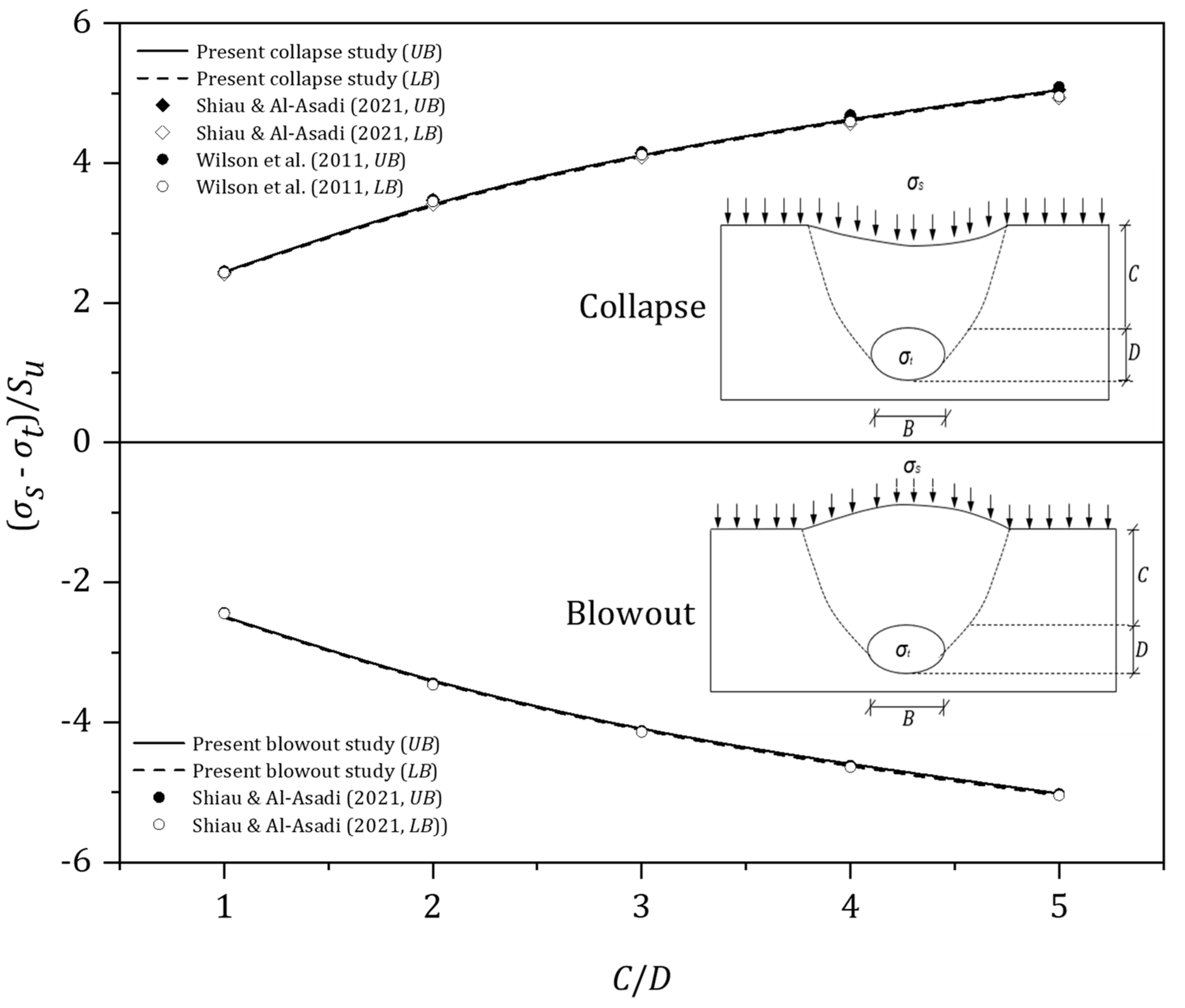
3. Results and Discussion
The blowout and collapse pressure ratios {PR = (σs − σt)/Su} versus the width to height ratio (B/D = 0.5 to 2) for various values of the depth ratio (C/D = 1–5) are presented in Figure 4a (for blowout) and Figure 4b (for collapse), respectively, for a weightless soil γD/Su = 0.
Figure 4.
(σs − σt)/Su vs (B/D) for various (C/D) − γD/Su = 0.
Due to the PR definition, a negative value of {PR = (σs − σt)/Su} means that the compressive normal supporting pressure (σt) is greater than the compressive surcharge pressure (σs). It is to be noted that negative PR values are seen for all blowout results. This is because (σt) must be greater than (σs) to cause a blowout failure. The larger the absolute value of PR, the greater the (σt). Numerical blowout results have shown that the pressure ratio (PR) increases, in negative PR, as (B/D) increases for all values of C/D. The increase in negative PR literally means a less critical blowout pressure (σt) is required to cause a blowout failure as (B/D) increases. Figure 4a. has also shown that the soil stability decreases (in negative PR) as the depth ratio (C/D) increases. Similar trends can be found in the blowout results (see Figure 5a, Figure 6a and Figure 7a) for dimensionless strength ratios (γD/Su = 1–3). As (γD/Su) increases, the system becomes heavier and therefore greater (σt) is required to cause a blowout.
Figure 5.
(σs − σt)/Su vs (B/D) for various (C/D) − γD/Su = 1.
Figure 6.
(σs − σt)/Su vs (B/D) for various (C/D) − γD/Su = 2.
Figure 7.
(σs − σt)/Su vs (B/D) for various (C/D) − γD/Su = 3.
In contrast, for the weightless collapse scenario, the PR values are always positive, i.e., (σs) must be greater than (σt) to cause a collapse. Numerical results in Figure 4b have shown that the pressure ratio (PR) decreases with increasing (B/D) for all the depth ratios (C/D). Furthermore, the soil stability increases as the depth ratio (C/D) increases. A symmetrical result can be found from both the collapse and blowout solutions.
Similar observations are noticed with the shear strength ratio (γD/Su = 1–3), as shown in Figure 5b, Figure 6b and Figure 7b. The “heavier” the system the larger the supporting pressure (σt) is needed to prevent collapse failure. As (γD/Su) increases, the value of PR becomes negative indicating the need of a supporting pressure for the active failure mechanism.
Using the same data, the effects of (C/D) are presented in Figure 8, Figure 9, Figure 10, Figure 11 and Figure 12. In general, for the blowout scenario (Figure 8a, Figure 9a, Figure 10a, Figure 11a and Figure 12a), the absolute values of the pressure ratio {PR = (σs − σt)/Su} increases as (C/D) increases. Note that the rate of increase (in negative PR) is greater as (γD/Su) increases. The finding is applicable to the various values of (B/D) of the blowout cases. Similar trends can be found in the collapse scenario (Figure 8b, Figure 9b, Figure 10b, Figure 11b and Figure 12b), where larger σt (in negative PR) is expected to support the soil as (γD/Su) increases. Furthermore, the larger the (C/D), the larger the σt (in negative PR) is. Design charts for assessing the blowout and collapse stability for various strength ratios (γD/Su = 0–3) are presented in Figure 13, Figure 14, Figure 15 and Figure 16, in which the x-axis represents the width to height (B/D) and the y-axis represents the depth ratio (C/D). One would need to input the “designed” parameters (B/D) and (C/D) to obtain a critical pressure ratio (PR) directly from the charts.
Figure 8.
(σs − σt)/Su vs (C/D) for various (γD/Su) − B/D = 0.5.
Figure 9.
(σs − σt)/Su vs (C/D) for various (γD/Su) − B/D = 0.75.
Figure 10.
(σs − σt)/Su vs (C/D) for various (γD/Su) − B/D = 1.
Figure 11.
(σs − σt)/Su vs (C/D) for various (γD/Su) − B/D = 1.33.
Figure 12.
(σs − σt)/Su vs (C/D) for various (γD/Su) − B/D = 2.
Figure 13.
Design charts for γD/Su = 0.
Figure 14.
Design charts for γD/Su = 1.
Figure 15.
Design charts for γD/Su = 2.
Figure 16.
Design charts for γD/Su = 3.
Contour plots of the absolute velocity fields of the elliptical cavity shape transformation are presented in Figure 17, Figure 18 and Figure 19 for various width to height ratios (B/D = 0.5, 1 and 2). These plots are both blowout and collapse modes with a shear strength ratio (γD/Su = 2) and two depth ratios (C/D = 1 and 3). In general, the failure extent in the collapse mode is greater than that in the blowout mode. This observation is supported by noting the location of the initial slip surface points from the inner cavity (see Figure 19). A chimney-type of failure is presented for the shallow depth ratio C/D = 1 in both the blowout and collapse scenarios and larger lateral expansions are seen in the deeper case C/D = 3, which supports the fact that greater σt is needed to cause soil blowout failure or to prevent soil collapse. Noting that the absolute values of the coloured velocity fields are not real for such a perfectly plasticity soil model, and therefore they are not presented here.
Figure 17.
Absolute velocity (|u|) contour plot (B/D = 0.5).
Figure 18.
Absolute velocity (|u|) contour plot (B/D = 1).
Figure 19.
Absolute velocity (|u|) contour plot (B/D = 2).
4. Comparison and Examples
Since there was no previous study on the soil stability of elliptical-shaped cavity under blowout condition, the comparison in Figure 20 is made by using previous circular cavity results (i.e., B = D) in either blowout or collapse scenarios. To compare the current pressure ratio (PR) with the critical stability number (Nc) in Shiau and Al-Asadi [35], a weightless soil condition (γD/Su = 0) is needed. In this way, our pressure ratio (PR) is equal to the (Nc) reported in Shiau and Al-Asadi [35]. The comparison shows a good agreement between Shiau and Al-Asadi [35] and the present study for the blowout study. Similarly, for the collapse study, it also shows a good arrangement amongst Shiau and Al-Asadi [35], Wilson et al. [36] and the present study. This comparison has greatly enhanced the confidence with the numerical results presented in the paper. An example is given next to explain how to use the design charts.
Figure 20.
Comparison of results.
A simple example: Evaluate the ground stability with the following given parameters: γ = 20 kPa, Su = 40 kPa, σs = 100 kPa, C = 6 m, D = 2 m and B = 1 m. Refer to Figure 3 for the notations.
Blowout Check
- Both the cover depth ratio and the width depth ratio are C/D = 3 and B/D =0.5, respectively.
- The strength ratio: SR = γD/Su = (20 × 2/40) = 1.
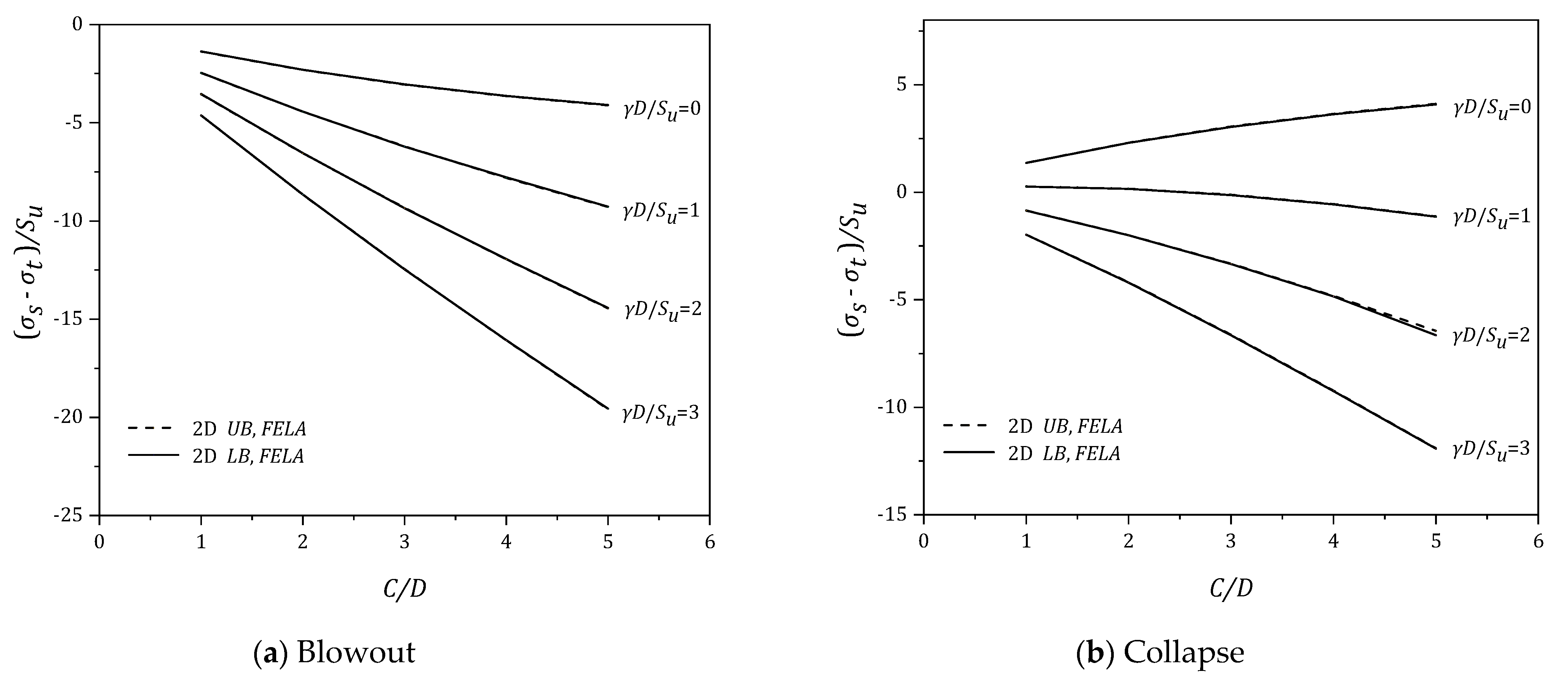
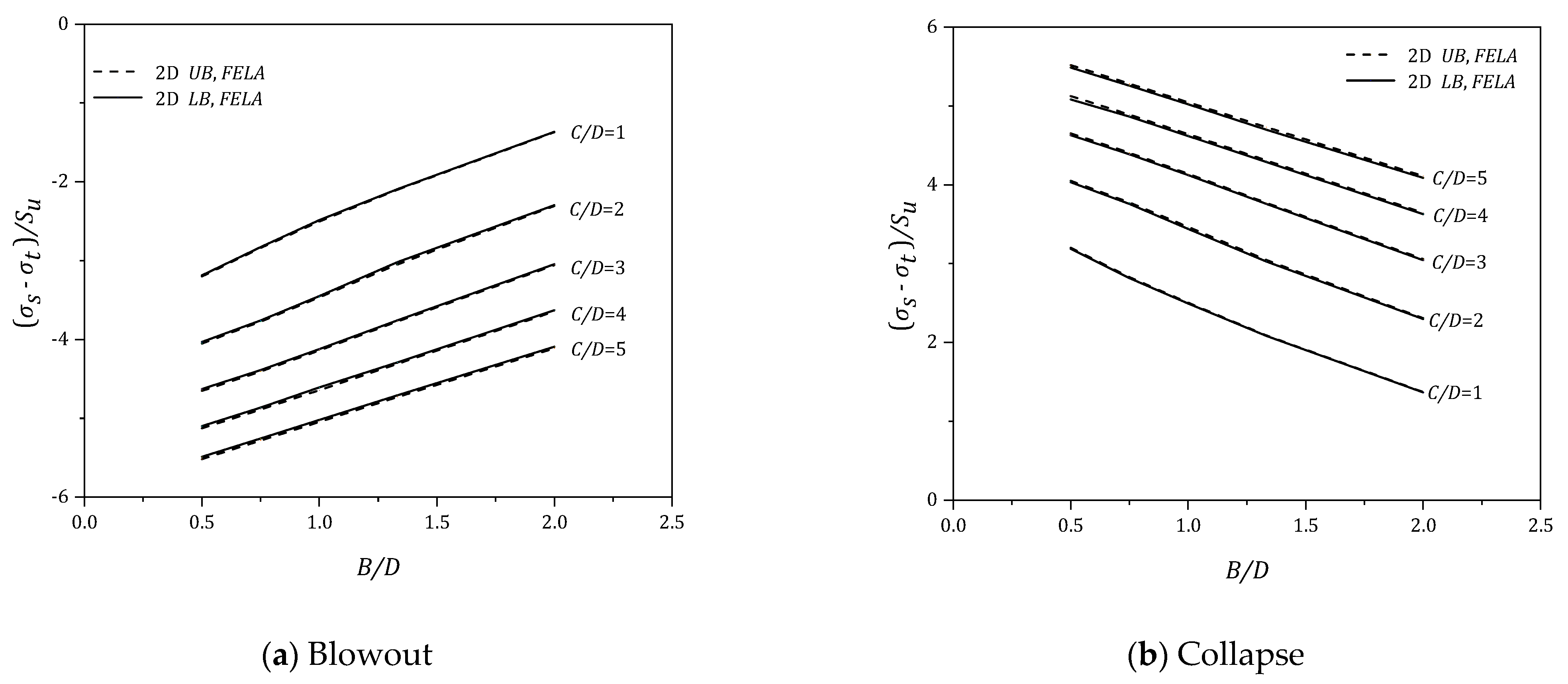
- Using Figure 14a, for C/D = 3 and B/D = 0.5, the critical pressure ratio is calculated as PR = (σs – σt)/Su = −7.9.
- Since σs = 100 and Su = 40 kPa, σt is calculated as 416 kPa. Theoretically, the support pressure should not be greater than 416 kPa, or a ground blow out failure occurs.
Collapse Check
- Both the cover depth ratio and the width depth ratio are C/D = 3 and B/D = 0.5, respectively.
- The strength ratio: SR = γD/Su = (20 × 2/40) = 1.
- Using Figure 14b, for C/D = 3 and B/D = 0.5, the critical pressure ratio is calculated as PR = (σs – σt)/Su = 1.2.
- Since σs = 100 and Su = 40 kPa, σt is calculated as 52 kPa. Theoretically, the cavity requires a support pressure of 52 kPa, or a ground collapse failure occurs.
5. Conclusions
Ground stability due to water main leakage-related sinkhole in blowout and collapse scenarios was investigated in this study using finite element limit analysis. Elliptical cavity shapes transformation was studied for a wide range of dimensionless ratios, namely the depth ratios, width to height ratios and soil strength ratios. The study was aimed to compute the rigorous upper and lower bounds of pressure ratios (PR). It was found that the thinner cavity (B/D = 0.5) provides better resistance than the wider one (B/D = 2), and the extent of surface failure increases with the increase in depth ratio irrespective of the opening shape. Numerical results obtained were compared with published literature, and comprehensive design charts and tables produced for practical uses with illustrated examples. It should be noted that the simulations in this paper are limited to 2D plane strain cavities which are close to the settlement phenomenon of the ground due to the excavation of unreinforced tunnels. The immediate future work will be the study on sinkholes with elliptical shape by using which the finite element limit analysis under axisymmetric conditions, which can provide a more realistic phenomenon of 3D sinkholes. In addition, future work recommendations may also include an elliptical-shaped transformation in cohesionless soil.
Author Contributions
Conceptualization, J.S. and S.K.; methodology, B.C., K.M. and S.S.; software, B.C., K.M. and S.S.; validation, B.C., S.S. and S.K.; formal analysis, B.C., K.M. and S.S.; investigation, S.S. and S.K.; resources, J.S. and S.K.; data curation, S.S. and S.K.; writing—original draft preparation, B.C., K.M. and S.S.; writing—review and editing, J.S. and S.K.; visualization, J.S. and S.K.; supervision, J.S. and S.K.; project administration, J.S.; funding acquisition, J.S. and S.K. All authors have read and agreed to the published version of the manuscript.
Funding
This work was supported by Thammasat University Research Unit in Structural and Foundation Engineering.
Institutional Review Board Statement
Not applicable.
Informed Consent Statement
Not applicable.
Data Availability Statement
The data and materials in this paper are available.
Conflicts of Interest
The authors declare no conflict of interest.
References
- Ali, H.; Choi, J. A review of underground pipeline leakage and sinkhole monitoring methods based on wireless sensor networking. Sustainability 2019, 11, 4007. [Google Scholar] [CrossRef] [Green Version]
- Waltham, T.; Bell, F.; Culshaw, M. Sinkholes and Subsidence: Karst and Cavernous Rocks in Engineering and Construction; Springer: Berlin/Heidelberg, Germany, 2005. [Google Scholar]
- Gutierrez, F.; Parise, M.; De Waele, J.; Jourde, H. A review on natural and human-induced geohazards and impacts in karst. Earth Sci. Rev. 2014, 138, 61–88. [Google Scholar] [CrossRef]
- Parise, M. Sinkholes. In Encyclopedia of Caves, 3rd ed.; White, W.B., Culver, D.C., Pipan, T., Eds.; Academic Press: Cambridge, MA, USA; Elsevier: Amsterdam, The Netherlands, 2019; pp. 934–942. [Google Scholar]
- Service Restored after Water Main Breaks in Front of Perry Hall Home-Opera News. 2021. Available online: https://www.dailyadvent.com/gb/news/4721acb8259e28c6cdd1ef23b70e1f6c-Service-Restored-After-Water-Main-Breaks-In-Front-Of-Perry-Hall-Home (accessed on 1 July 2021).
- News Break. Storm Sewer Collapse Leads to Sinkhole in Maryville. 2021. Available online: https://www.newsbreak.com/news/2198607773329/storm-sewer-collapse-leads-to-sinkhole-in-maryville (accessed on 1 July 2021).
- NewsComAu. Pipe Bursts in Sydney Street before Sinkhole Opens Up. 2021. Available online: https://www.news.com.au/national/nsw-act/news/sinkhole-opens-up-on-newport-nsw-road-after-water-pipe-bursts/news-story/1068cc414cd5da051d5453a88ecf4ef5 (accessed on 1 May 2021).
- WionNews (WION). Italy: Giant Sinkhole in Rome Swallows Two Parked Cars. 2021. Available online: https://www.wionews.com/world/italy-giant-sinkhole-in-rome-swallows-two-parked-cars-387462 (accessed on 2 July 2021).
- Indiketiya, S.; Jegatheesan, P.; Rajeev, P.; Kuwano, R. The influence of pipe embedment material on sinkhole formation due to erosion around defective sewers. Transp. Geotech. 2019, 19, 110–125. [Google Scholar] [CrossRef]
- Sloan, S.W.; Assadi, A.; Purushothaman, N. Undrained stability of a trapdoor. Géotechnique 1990, 40, 45–62. [Google Scholar] [CrossRef]
- Martin, C.M. Undrained collapse of a shallow plane-strain trapdoor. Géotechnique 2009, 59, 855–863. [Google Scholar] [CrossRef]
- Shiau, J.; Lamb, B.; Sams, M. The use of sinkhole models in advanced geotechnical engineering teaching. Int. J. GEOMATE 2016, 10, 1718–1724. [Google Scholar] [CrossRef]
- Wang, L.; Leshchinsky, B.; Evans, T.M.; Xie, Y. Active and passive arching stress in C’-Φ’ soils: A sensitivity study using computational limit analysis. Comput. Geotech. 2017, 84, 47–55. [Google Scholar] [CrossRef]
- Keawsawasvong, S.; Ukritchon, B. Undrained stability of an active planar trapdoor in non-homogeneous clays with a linear increase of strength with depth. Comput. Geotech. 2017, 81, 284–293. [Google Scholar] [CrossRef]
- Keawsawasvong, S.; Ukritchon, B. Undrained stability of plane strain active trapdoors in anisotropic and non-homogeneous clays. Tunn. Undergr. Space Technol. 2021, 107, 103628. [Google Scholar] [CrossRef]
- Keawsawasvong, S.; Likitlersuang, S. Undrained stability of active trapdoors in two-layered clays. Undergr. Space 2021, 6, 446–454. [Google Scholar] [CrossRef]
- Shiau, J.; Al-Asadi, F. Three-Dimensional Analysis of Circular Tunnel Headings Using Broms and Bennermark’s Original Stability Number. Int. J. Geomech. 2020, 20, 06020015. [Google Scholar] [CrossRef]
- Shiau, J.; Hassan, M.M. Undrained stability of active and passive trapdoors. Geotech. Res. 2020, 7, 40–48. [Google Scholar] [CrossRef] [Green Version]
- Shiau, J.; Chudal, B.; Mahalingasivam, K.; Keawsawasvong, S. Pipeline burst-related ground stability in blowout condition. Transp. Geotech. 2021, 29, 100587. [Google Scholar] [CrossRef]
- Fazio, N.L.; Perrotti, M.; Lollino, P.; Parise, M.; Vattano, M.; Madonia, G.; Di Maggio, C. A three-dimensional back analysis of the collapse of an underground cavity in soft rocks. Eng. Geol. 2017, 238, 301–311. [Google Scholar] [CrossRef]
- Fiore, A.; Fazio, N.L.; Lollino, P.; Luisi, M.; Miccoli, N.M.; Pagliarulo, R.; Perrotti, M.; Pisano, L.; Spalluto, L.; Vennari, C.; et al. Evaluating the susceptibility to anthropogenic sinkholes in Apulian calcarenites, southern Italy. In Advances in Karst Research: Theory, Fieldwork and Applications; Parise, M., Gabrovsek, F., Kaufmann, G., Ravbar, N., Eds.; Special Publications; Geological Society: London, UK, 2018; Volume 466, pp. 381–396. [Google Scholar]
- Perrotti, M.; Lollino, P.; Fazio, N.L.; Pisano, L.; Vessia, G.; Parise, M.; Fiore, A.; Luisi, M. Finite Element–based stability charts for underground cavities in soft calcarenites. Int. J. Geomech. 2018, 18, 04018071. [Google Scholar] [CrossRef]
- Lollino, P.; Perrotti, M.; Fazio, N.L.; Parise, M. Sinkhole Susceptibility Assessment of Underground Caves in Soft Rocks by Means of FEM-Based Charts; American Rock Mechanics Association Symposium: New York, NY, USA, 2019; 19-A-2026-ARMA. [Google Scholar]
- Dutta, P.; Bhattacharya, P. Determination of internal pressure for the stability of dual elliptical tunnels in soft clay. Geomech. Geoengin. 2021, 16, 67–79. [Google Scholar] [CrossRef]
- Yang, F.; Sun, X.; Zou, J.; Zheng, X. Analysis of an elliptical tunnel affected by surcharge loading. Proc. Inst. Civ. Eng.-Geotech. Eng. 2019, 172, 312–319. [Google Scholar] [CrossRef]
- Zhang, J.; Yang, J.; Yang, F.; Zhang, X.; Zheng, X. Upper-bound solution for stability number of an elliptical tunnel in cohesionless soils. Int. J. Geomech. 2017, 17, 06016011. [Google Scholar] [CrossRef]
- Yang, F.; Zhang, J.; Yang, J.; Zhao, L.; Zheng, X. Stability analysis of unlined elliptical tunnel using finite element upper-bound method with rigid translatory moving elements. Tunn. Undergr. Space Technol. 2015, 50, 13–22. [Google Scholar] [CrossRef]
- Yang, F.; Sun, X.; Zheng, X.; Yang, J. Stability analysis of a deep buried elliptical tunnel in cohesive–frictional (c–ϕ) soils with a nonassociated flow rule. Can. Geotech. J. 2017, 54, 736–741. [Google Scholar] [CrossRef]
- Yang, M.Z.; Drumm, E.C. Stability evaluation for the siting of municipal landfills in karst. Eng. Geol. 2002, 65, 185–195. [Google Scholar] [CrossRef]
- Drumm, E.C.; Aktürk, Ö.; Akgün, H.; Tutluoğlu, L. Stability charts for the collapse of residual soil in karst. J. Geotech. Geoenvironmental Eng. 2009, 135, 925–931. [Google Scholar] [CrossRef]
- Ukritchon, B.; Yoang, S.; Keawsawasvong, S. Three-dimensional stability analysis of the collapse pressure on flexible pavements over rectangular trapdoors. Transp. Geotech. 2019, 21, 100277. [Google Scholar] [CrossRef]
- OptumCE, OptumG2. Copenhagen, Denmark: Optum Computational Engineering. 2021. Available online: https://optumce.com/ (accessed on 25 June 2021).
- Broms, B.B.; Bennermark, H. Stability of clay at vertical openings. J. Soil Mech. Found. Div. 1967, 93, 71–94. [Google Scholar] [CrossRef]
- Davis, E.; Gunn, M.; Mair, R.; Seneviratine, H. ‘The stability of shallow tunnels and underground openings in cohesive material. Geotechnique 1980, 30, 397–416. [Google Scholar] [CrossRef]
- Shiau, J.; Al-Asadi, F. Revisiting circular tunnel stability using Broms and Bennermarks’ Original Stability Number. Int. J. Geomech. 2021, 21, 06021009. [Google Scholar] [CrossRef]
- Wilson, D.W.; Abbo, A.J.; Sloan, S.W.; Lyamin, A.V. Undrained stability of a circular tunnel where the shear strength increases linearly with depth. Can. Geotech. J. 2011, 48, 1328–1342. [Google Scholar] [CrossRef]
Publisher’s Note: MDPI stays neutral with regard to jurisdictional claims in published maps and institutional affiliations. |
© 2021 by the authors. Licensee MDPI, Basel, Switzerland. This article is an open access article distributed under the terms and conditions of the Creative Commons Attribution (CC BY) license (https://creativecommons.org/licenses/by/4.0/).