Article

Investigation of Geological Anomalies at Pile Foundation Location in Urban Karst Areas Using Single Borehole Radar

1
Key Laboratory of Geotechnical and Underground Engineering of Ministry of Education, Department of Geotechnical Engineering, Tongji University, Shanghai 200092, China
2
Department of Geotechnical Engineering, College of Civil Engineering, Tongji University, Shanghai 200092, China
3
Department of Geology, The University of Kansas, Lawrence, KS 66045, USA
*
Author to whom correspondence should be addressed.
Geosciences 2020, 10(6), 232; https://doi.org/10.3390/geosciences10060232
Submission received: 20 May 2020 / Revised: 6 June 2020 / Accepted: 9 June 2020 / Published: 16 June 2020
(This article belongs to the Special Issue Urban Geophysics)

Abstract

:
Karst geological anomalies at pile locations significantly affect the bearing capacity and construction safety of the piles, posing a significant challenge for urbanization. Borehole geophysical methods are required to extend the detection range and identify karst voids that are at pole locations and near drilled boreholes. In this paper, we developed a near offset and small diameter single borehole ground penetration radar (GPR) prototype. A signal processing method combining complex signal analysis by Hilbert transform (HT) and medium filtering was suggested to differentiate the weak backscattered wave from borehole background noise. A controlled horizontal borehole experiment was used to demonstrate the applicability of the prototype and the advantages of the signal analysis method prior to application in a real project. The controlled test presented three typical wave events corresponding to a soil–rock interface, rock fractures, and karst voids. Field tests were conducted at a freeway bridge extension project in an urban karst area. Multiple karst voids, sinkholes, rock fractures, and integrated bedrock were identified by analysis of four typical detection scenarios. The remediation of the karst voids and a rotary bored piling with real-time steel casing construction strategy were designed based on the investigation results. The construction feedback demonstrates that single borehole radar detection is effective for the investigation of anomalies at pile locations in urban karst areas.

1. Introduction

The most common problem associated with urbanization in karst areas is the construction of large buildings on unstable ground. Karst collapses can be detrimental to (and potentially hastened by) construction [1]. Karst voids in bedrock and sinkholes in regolith significantly reduce the load-bearing capacity of the pile foundation and create risks for construction [2]. Urbanization and infrastructure construction require effective on-site investigations to detect karst geological anomalies and assist with the design of the appropriate type and depth of piles and safe construction methods [3,4,5].
Ground penetration radar (GPR) [6,7] and other surface geophysical methods, including multichannel analysis of surface waves (MASW) [8,9], electrical resistivity tomography (ERT) [10,11], the transient electromagnetic method (TEM) [12,13], and traditional seismic reflection [14,15,16] can be used to provide information for determining the general distribution of karst geological anomalies. However, due to thick and complex overburden, deep karst voids are difficult to detect at high resolution using surface geophysical techniques [3]. The most common practice for the geological investigation of deep pile foundation is drilling a borehole at each pile location. However, sufficient information to enable the safety of pile construction cannot be gathered due to limits in the size and number of boreholes [17,18]. Borehole geophysical techniques are required to extend a borehole’s detection range from “point detection” to “volume exploration” and provide more geological information to designers [3,19].
Borehole radar [20,21,22,23,24] is a rapidly developing borehole geophysical method that can be operated in either cross-hole tomography or a single borehole reflection survey. Cross-hole radar detection can provide a velocity model and the distribution of the attenuation coefficient between two boreholes. Full-waveform inversion and Bayesian inversion [25,26] can be used to invert the conductivity and permittivity of the stratum. Single borehole radar can locate the geological anomalies away from the borehole walls [27]. Compared to cross-hole detection, single borehole detection is more time- and cost-saving in both data collection and processing, which is more feasible to investigate the karst anomalies at every single pile location. Time–frequency analysis and filtering [27,28] provide a powerful method to process the GPR data and extract weak effective signal from noise.
In this contribution, a near offset and small diameter single borehole GPR prototype system was developed for the detection of karst voids at piles location. A rapid data processing method combining complex signal analysis by Hilbert transform (HT) and medium filtering was suggested to extract weak backscattered waves from the distant geological reflectors and identify the infill of the karst voids. A controlled horizontal borehole experiment was used to demonstrate the applicability of the prototype and to analyze and interpret the data analysis method. Field single borehole radar detections were conducted in a freeway bridge extension project in an urban karst area—Guangzhou, China. Typical single borehole radar detection data of different karst geological anomalies were analyzed. The construction methods of piles and the remediation of different karst anomalies were concluded based on the detection results and ongoing construction feedback.

2. Single Borehole Radar Detection

2.1. Detection Object

Karst geology, including sinkholes, boulders, and karst voids, is randomly distributed at pile locations, as shown in Figure 1a, and significantly affects bearing capacity and construction safety. Bearing capacity of a pile typically comes from skin friction and the end bearing. The slide skin friction in the depth range of a sinkhole or karst voids (e.g., the sinkhole and the three shallow karst voids in Figure 1a) should be completely deducted when calculating the bearing capacity of the pile. The end bearing capacity plays a more important role in karst areas. However, karst geological anomalies, including voids, fractures, and regional rock dissolution beneath the pile (e.g., the deepest karst void in Figure 1a) significantly reduce the capacity of the pile. Regarding construction safety, the following four types of incidents are likely due to unknown karst anomalies at the pile location: (1) stuck drill, where impacting drilling with a long and heavy stroke distance is extremely dangerous when the drilling penetrates the thin roof of karst voids; (2) leakage of slurry, where the slurry in the pile hole drains away when the drilling penetrates karst voids or a fracture flow tunnel; (3) inclined pile hole, where pile holes have a high risk of being inclined when drilling uneven or irregular geological interfaces; and (4) collapse of the pile hole. All of the above incidents may cause the collapse of a pile hole if they are not dealt with adequately.
False-negative karst anomaly detection is highly dangerous, as undetected and untreated karst voids could lead to improper bearing capacity design and construction methods. Single borehole GPR detection (Figure 1b) is used to probe the full diameter of the pile combined with the existing borehole, with the aim of providing better geological details for the design of bearing capacity and construction methods.

2.2. Single Borehole GPR Prototype System

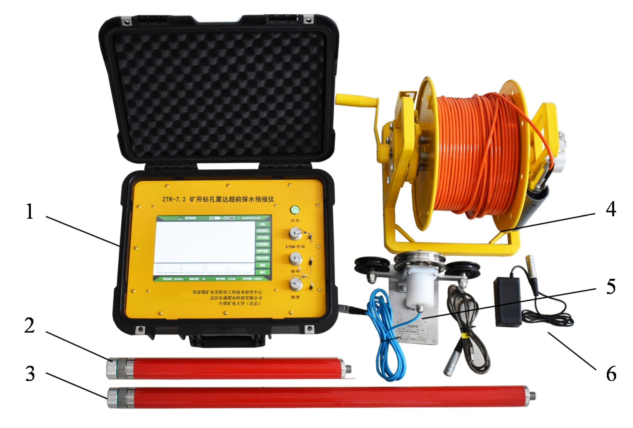
The single borehole GPR prototype (Figure 2) is a pulse GPR system consisting of a surface computer, transmitting and receiving antenna, fiber cable, depth counter, and charger. The downhole antenna is connected to a computer using a fiber cable. The fiber cable passes through the depth counter and records the depth of the probe. The transmitting antenna is an omnidirectional dipole made with two conical copper tubes, and has a frequency range from 20 MHz to 200 MHz. The receiving antenna has the same structure as the transmitting antenna and is installed with a 16-bit A/D converter. In the test, the borehole GPR downhole transmitting and receiving antenna shown in Figure 2 is lowered from the top to the bottom of the borehole with a velocity of 0.1 m/s using the ground support shown in Figure 1b. Electromagnetic (EM) waves are transmitted every 0.1 m in depth. The waves propagate through and along the borehole and reflect from impedance interfaces, after which the waves are received and preprocessed by the receiving antenna. The EM wave profile is presented and analyzed by the in situ computer.
The system features a small diameter (36 mm) and near offset (30 cm), which are two critical factors for detecting karst voids at pile locations. The diameter of a drilling borehole in the rock layer is about 70 mm. PVC tubes are necessarily applied in borehole GPR detection in karst areas to prevent the falling of the infill of voids, and unstable and disturbed rocks into the borehole which would trap the antennae. PVC tubes are installed after drilling, thus, the device is easier to operate when the diameter of PVC tubes is small. A downhole tool of small diameter is more feasible for a civil engineering project. On the other hand, the geological anomaly varies dramatically with a small change in depth in karst areas. The near offset acquisition system ensures high resolution and makes it possible to use a medium filter to remove the direct wave and borehole reflection background noise.

2.3. Signal Analysis

In the signal analysis of the single borehole EM wave profiles, static correction can be simplified as zero-time correction since the interval between the transmitting and receiving antennas is small. Bandpass frequency filtering is used to focus on the dominant frequency of the antennas.
To make the faint backscatter visible, gain control (amplitude-based) and complex signal analysis (instantaneous phase-based) are effective methods. The instantaneous phase presents the faint event regardless of the attenuation of the amplitude, which is more appropriate for the processing of the GPR data from the karst area borehole tests. This is because the saturated soil and rock in the karst area significantly attenuate the energy of the EM wave. The Hilbert transform is used to calculate the instantaneous phase. Taking one depth test signal sx(t) as an example, an analytic signal zx(t) is constructed, which includes the real component sx(t) and the imaginary component yx(t) that can be constructed using the HT [29]:
z x ( t ) = s x ( t ) + i y x ( t ) ,
where the imaginary component yx(t) is obtained via the Hilbert transform of sx(t):
y x ( t ) = H ( s x ( t ) ) = 1 π + s x ( τ ) t τ d τ ,
where H(sx(t)) is the Hilbert transform of sx(t). The instantaneous phase ϕx(t) of the signal sx(t) can be obtained as follows:
ϕ x ( t ) = a r c t a n y x ( t ) s x ( t )
Median filtering can be used to extract the effective reflected waves and remove borehole background noise. The single borehole EM wave profiles, P(t, x), typically contain direct waves, waves in the borehole, and reflected waves from the geological structure outside the borehole. The direct waves and the multiple reflected EM waves in the borehole exhibit constant and small arrival times because of the near offset acquisition system. However, most backscatter EM waves from the geological structure have sloping and variable time appearance since the wave travel distance between the probe of the geological structures varies along the borehole. Thus, median filtering can be used to remove the constant time arrivals while preserving variable time. The procedure of the median filter is as follows:
(a)
Taking the test signal at one depth sx(t) as an example, a new set of sequences can be formed by reading the test signals of 2N + 1 channels at adjacent depths (sx-N(t), sx-N+1(t)… sx+N(t)).
(b)
For every point at time sx(tn), the amplitudes of the test signals of 2N + 1 channels (sx-N(tn), sx-N+1(tn)… sx+N(tn)) are reordered. The median sxm(tn) replaces the original amplitude sx(tn) in the test signal sx(t).
(c)
Repeat steps (a) and (b) for all the recordings. A new wave can be obtained as a Pm(t, x) profile after median filtering, which consists of the direct wave and waves in the borehole.
(d)
The wave profiles Pr(t, x) can be calculated as Pr(t, x) = P(t, x) − Pm(t, x), which mainly contain the reflected waves from the geological structure.

3. Validation by a Controlled Experiment

The performance of single borehole radar and its signal analysis method was tested in a field horizontal borehole experimental setting. Controlled tests are explained as follows: (1) the typical wave field and profile of borehole GPR detection, (2) the capability to identify typical karst points and linear fracture anomalies, and (3) the performance of the instantaneous phase and medium filtering in making weak diffraction more evident.

3.1. Experiment Setting

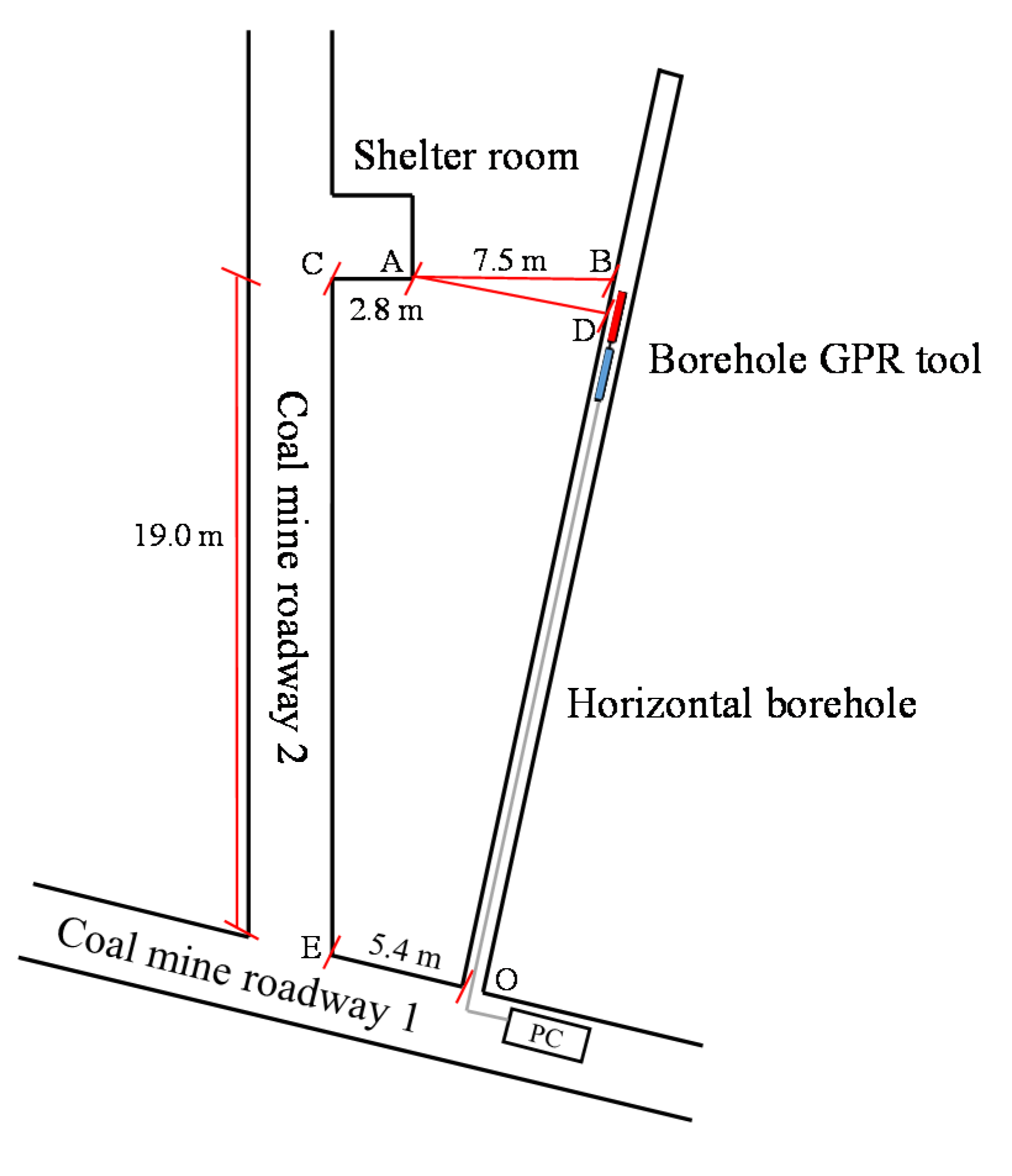
A controlled horizontal borehole experiment was conducted at a roadway crossing a coal mine located at Datong Mine, Chongqing, China. The roadway surrounding is saturated limestone, which is consistent with the lithology in karst areas. The geometry set is shown in Figure 3. A horizontal borehole was drilled on roadway 1 to generate an image of roadway 2 and a shelter room on roadway 2 using single borehole GPR detection. The interface of roadway 1, roadway 2, and the shelter room was used to simulate a soil-rock interface, linear rock fracture, and a point shape karst void, respectively, which are three typical geologic structures of concern to engineers in karst areas. Considering the attenuation of high-frequency EM waves in saturated rock, a pair of borehole antennae of relatively lower frequency (30 MHz) was used in the controlled test because large energy transmission is not allowed in the mine due to security concerns.

3.2. Results

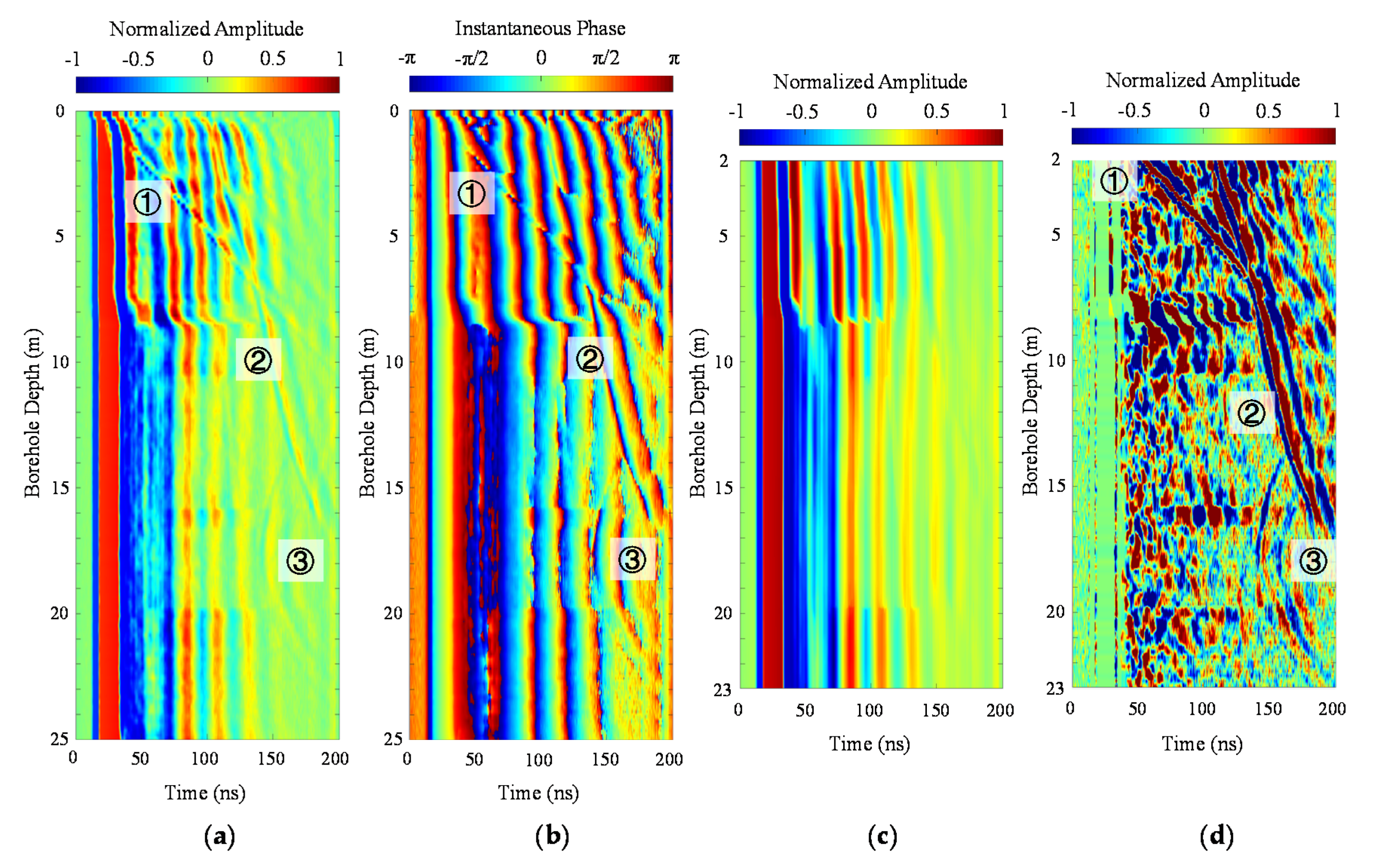
The EM wave profiles of the controlled horizontal borehole experiment are shown in Figure 4. Multiple constant arrival events can be observed in the original data (Figure 4a), which are direct wave events and multiple reflections in the borehole. These background noises are continuous along the borehole depth. A slight discontinuity occurs at a depth of 8.5 m as the saturation changes. The shallow portion has a dryer rock formation, where the velocity of EM waves is slightly higher than those in the deeper and more saturated formation. Two weak sloping events can be barely seen in Figure 4a. Event 1 shown in Figure 4a is clear; however, Event 2 is not as clear as Event 1 since the amplitude of the reflected wave is faint and likely to be neglected if the gain control is not set well. Event 3 represents hyperbolic reflected waves, but the backscattered energy is weak.
According to the instantaneous phase of the EM wave profiles in Figure 4b, distant events become more evident. Event 1 is still clear at the end of sampling time (200 ns and 10.5 m deep). Event 1 represents guided waves traveling along the borehole and reflected at the interface with permittivity change (i.e., the surface of coal mine roadway 1 shown in Figure 3). Thus, the velocity of the EM waves in the formation can be estimated as below:
V = 2d/t = 2 × 10.5 m/200 ns = 0.105 m/ns.
The estimated velocity is consistent with the EM wave velocity in limestone. Based on this velocity, Event 2 can be interpreted as backscattered waves from the surface of coal mine roadway 2. Event 3 corresponds to the backscatter from the shelter room on roadway 2. At the entrance of the borehole (0 m deep), the backscattered wave arrives at approximately 100 ns (Figure 4b). Thus, the distance between the borehole entrance and roadway 2 (EO separation in Figure 3) can be calculated as 5.25 m.
Medium filtering is applied to remove the borehole background noise and identify the accurate arrival time of the backscattered waves. The removed waves and filtered waves are shown in Figure 4b. The earliest arrival time of Event 3 can be observed at 137 ns (18.1 m deep). The distance between the nearest point in the borehole (point D in Figure 3) and the near corner of the shelter room can be calculated as 7.19 m, which is close to the real point D position. The error can be caused by the different EM wave velocity in the concrete near the shelter room. The backscatter from roadway 2 (Event 2) ends at a depth of 18 m, where the shelter room appears. The phase of the backscattered waves can be observed clearly in Figure 4d. All three events do not show phase reversal, which is consistent with the characteristics of air-filled anomaly reflection.
The controlled experiment shows that three typical backscattered events can occur in a single borehole GPR detection. In Figure 4, Event 1 represents a linear backscattered event corresponding to a geological interface across the borehole (e.g., regolith-bedrock contact and rock fracture). The slope of this type of event can be used to estimate the EM wave velocity. Event 2 corresponds to linear rock fractures that are located outside the borehole. The slope of the event can reflect the shape and trend of the fracture. Event 3 is a typical hyperbolic backscatter, which indicates a point-sharped geological anomaly (e.g., karst voids, sinkholes, and boulders). Instantaneous phase analysis and medium filtering emphasize the faint events and make the phase of the backscatter visible, which is helpful to determine the infill in the anomaly.

4. Field Test

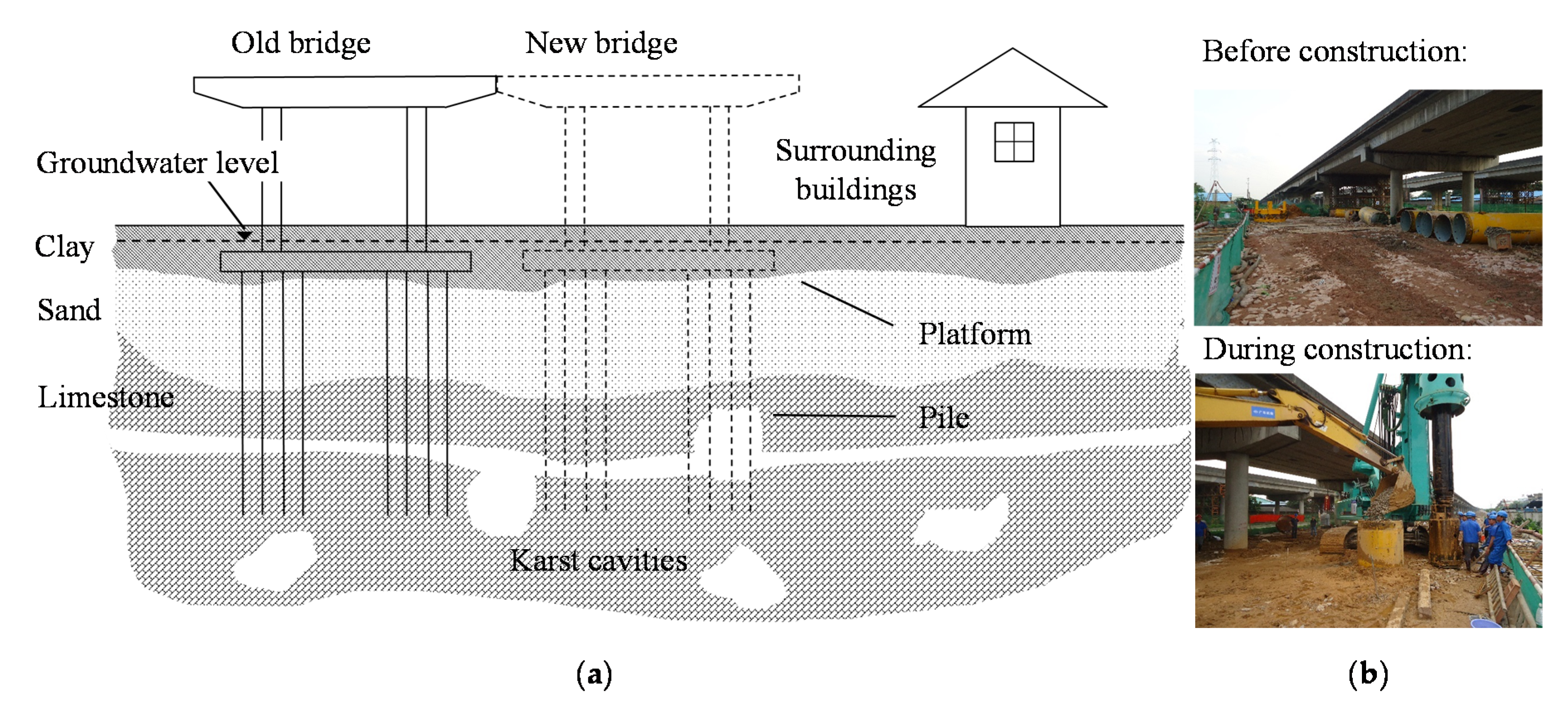
Single borehole GPR detection tests were conducted on a freeway extension project in Guangzhou, a metropolis in southern China. The project aims to replace a four-lane road with a new eight-lane freeway (Figure 5a). The total length of the project is 57.6 km, 33 km of which is in karst. The part of the extension project in the karst area includes more than 3000 piles. Underground karst voids endanger the bearing capacity of the piles, the safety of their construction, and surrounding buildings. The regolith in the study area consists of Quaternary material with a thickness of approximately 15–25 m. The overburden contains plain fill, silty clay, and silty sand. The bedrock layer is medium-weathered and weakly weathered limestone. Multiple karst cavities are common in the project area. Single borehole GPR detection was employed in this project to identify the karst geological anomalies at the pile locations. Four typical scenarios at different pile locations, namely, karst voids (ZK-4-11 borehole, a pile location at the bridge project Section 4, the first number of the borehole was named by the section of the project route), sinkholes (ZK-2-23 borehole), rock fractures (ZK-7-13 borehole), and integrated rock (ZK-4-36 borehole) are discussed in this section.

4.1. Scenario 1: Karst Voids

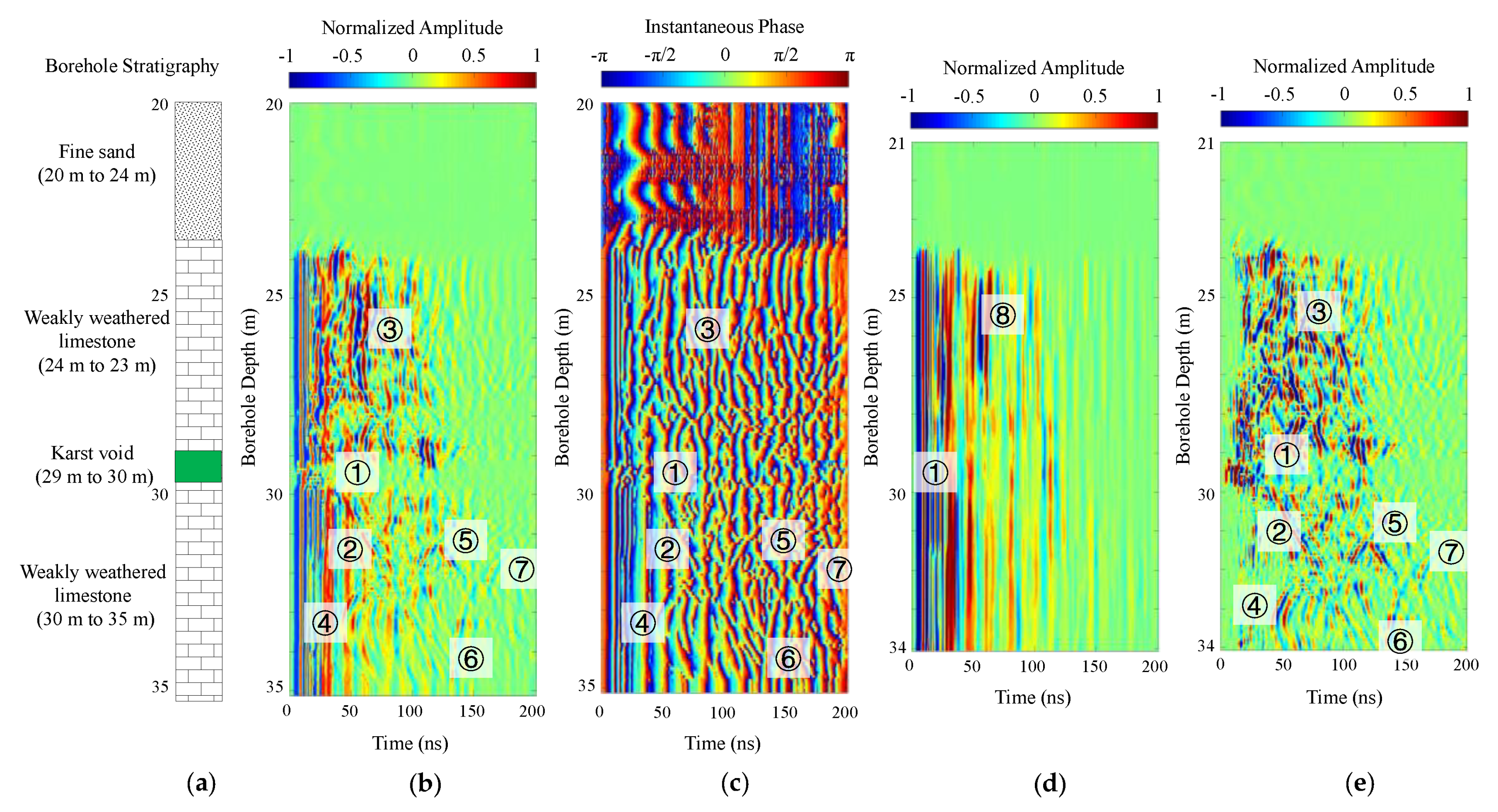
ZK-4-11 borehole was drilled at a planned pile location, which shows a 1 m large karst void from 29 m to 30 m deep. A soil–rock interface is at 24 m. The borehole stratigraphy (Figure 6a) shows that the limestone is weakly weathered with more than 60 RQD values. The pile depth should be designed directly beneath the karst void floor at around 30 m deep. However, a single borehole GPR detection identifies multiple karst geological anomalies at the pile location.
The processed radar data after zero-correction and band-pass filtering are shown in Figure 6b. Event 1 shows that the direct EM waves and borehole reflections are discontinued at the depth of 29 m, which is consistent with the borehole stratigraphy. Events 2 and 3 are linear and intersect at the borehole depth of 28 m, which suggests a rock fracture that the borehole stratigraphy missed. Event 4 corresponds to hyperbolic reflected waves and indicates a karst cavity around the borehole. Similar hyperbolic reflected waves can be observed from Event 5, 6, and 7. These hyperbolic events at depths of 30–35 m all indicate multiple karst voids at the pile location.
The instantaneous phase and median filtered data are shown in Figure 6c–e, which provide more details. The backscatter behind Event 1 is not visible in Figure 6b because of the significant attenuation of EM waves in the water or saturated soil-filled karst cavity. However, the borehole reflection behind Event 1 can be identified in the instantaneous phase (Figure 6c) and removed waves profile (Figure 6d). Both Event 2 and 3 are more pronounced in the instantaneous phase and median filtered waves (Figure 6e). Event 2 discontinues at the depth of 30 m and presents a consistent linear trend from 28 m to 35 m deep. The backscattered wave from the rock fracture at the depth of 28 m decays slowly, which indicates the surrounding rock is integrated at a certain azimuth. Based on the slope of the event, the EM velocity in the limestone is estimated to be 0.112 m/ns. Thus, Events 4, 5, 6, and 7 indicate three karst cavities that are approximately 2.2, 5.7, and 7.5 m from the borehole. Events 6 and 7 correspond to the same cavity as the two events are continuous in the instantaneous phase. Phase reversal of Events 4 to 7 is visible in the median filtered wave (Figure 6e), which suggests the three cavities are filled with water or saturated soil. Additionally, Figure 6d presents an amplitude anomaly at the depth of 25 m (Event 8), which corresponds to a karst void whose outline is parallel to the borehole. According to the single borehole GPR detection result, it is unsafe to design the bearing layer at 30 m. The borehole should be deepened to search for another integrated bedrock range.
According to the feedback from the pile construction of borehole ZK-4-11 (scenario 1), a steel casing was lowered to 35 m to protect the pile hole from collapse. The foot blade of the casing was enhanced at the depth of 24 m (soil–rock interface), 28 m (a rock fracture identified by the borehole radar detection), 29 m and 30 m (the top and floor, respectively, of the karst void identified by the borehole), and 33 m and 35 m (the top and floor, respectively, of the karst void identified by the borehole radar detection). Artificial construction materials were deposited, mixed, and compacted at the depth of 24, 29, and 33 m to remedy the karst voids.

4.2. Scenario 2: Sinkhole

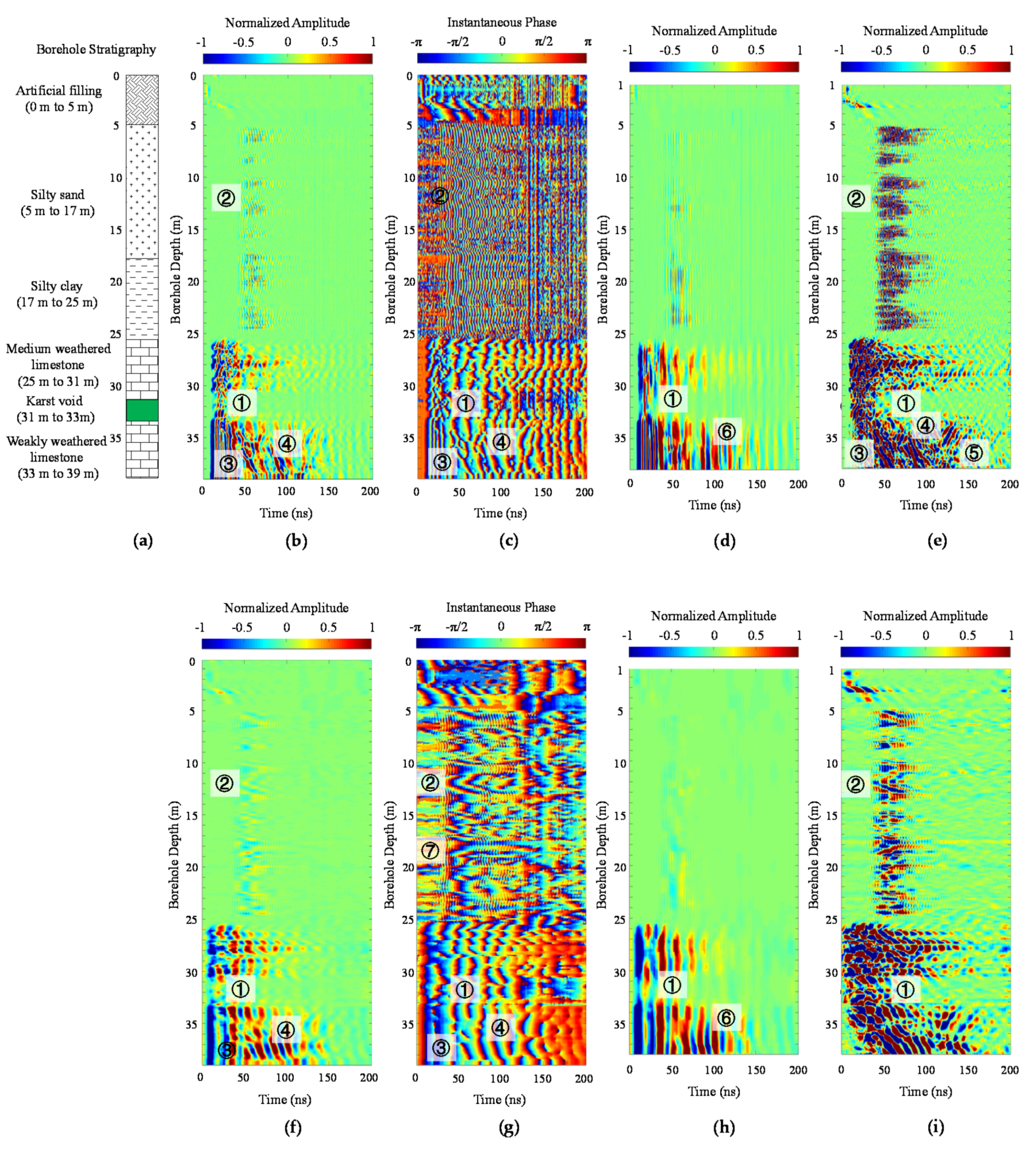
The borehole stratigraphy of the ZK-2-23 borehole indicates a 1 m diameter karst cavity from 31 to 33 m deep. The overburden contains artificial filling, fine sand, and silty clay. The upper bedrock is medium-weathered limestone, whose RQD is approximately 30. The lower layer is weakly weathered limestone, whose RQD is larger than 60. The original borehole GPR data demonstrate the observations from the borehole stratigraphy in the bedrock layer.
The GPR data also identify a karst void as the weak direct wave in the depth range of 31–33 m (Event 1 in Figure 7). The direct wave events from 25 m to 31 m are more irregular than those from 33 m to 39 m, which suggests the rock from 25 to 31 is more weathered and dissolved. After employing the Hilbert transform and medium filtering, the reflected EM waves from the geological structure behind the borehole are identified at Events 3, 4, 5, and 6. Event 3 corresponds to a linear rock fracture intersect at the borehole depth of 30 m. Events 4 and 5 are two hyperbolic backscattered waves from the two karst voids. The distance between the borehole and the two voids can be estimated as 4.4 m and 7.0 m.
Differently from the data of scenario 1, the waveform of scenario 2 does not show a frequency decrease in the soil layer. Weak high-frequency signals (Event 2, approximately 300 MHz) can be seen in the original borehole GPR data. Repeated tests demonstrate that the high-frequency signals are not random background noise. The frequency range of the transmitting antenna is 30–200 MHz, thus, the high-frequency data is ringing (reverberation, 300 MHz) from the signal inside the borehole.
To extract effective events, FIR low-pass filtering is used. Note that there is a weak hyperbolic reflected wave event at the depth of 12 m in the low-pass filtered data in Figure 7f. The slope of the hyperbola becomes more evident after instantaneous phase analysis and median filtering in Figure 7g,h. The EM velocity is estimated as 0.034 m/ns based on the slope of the hyperbola, which signifies the EM waves are propagating in water and the reflector is approximately 0.6 m from the borehole. However, the diameter of the borehole drill is 0.1 m. The borehole was enlarged because of the disturbance of drilling and the loss of surrounding soil. A sinkhole is empirically formed when cavities in bedrock collapse, or where covering materials such as sand, silt, or clay funnel into the cavities. Thus, this borehole is at high risk of a sinkhole since there is a karst void in the bedrock, loss of covering materials in the silty sand and clay layer, and a medium-weathered limestone layer that provides a channel to funnel soil into the karst void. Remediation of the sinkhole is required before construction.
Compaction grouting of the sinkhole was employed in a depth range of 10 to 25 m (i.e., from the soil–rock interface to the top of the sinkhole) before construction. Cement, sodium silicate, crushed stone, and red clay were deposited, mixed, and compacted at the depth of 25 and 31 m. In the pile construction, the steel casing was lowered to 37 m and enhanced at critical interfaces (25, 31, and 33 m deep).

4.3. Scenario 3: Rock Fracture

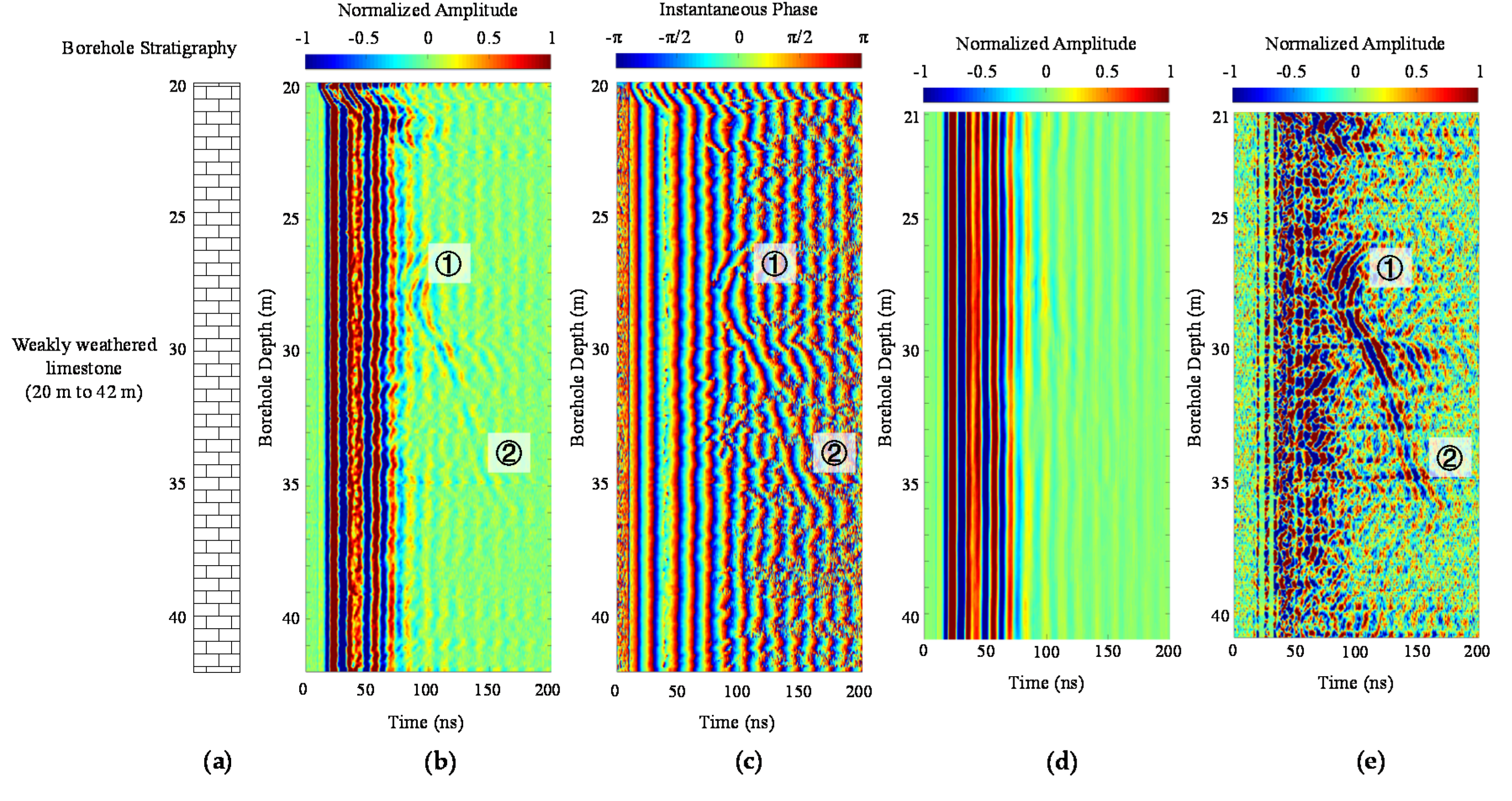
Weakly weathered limestone can be identified from 20 to 42 m from the borehole stratigraphy of ZK-7-13 (Figure 8a). The RQD values of the drilling core are more than 70. The borehole is located in an area in which karst rarely develops, but, nonetheless, the minor dissolution of limestone can be observed in this field area. Single borehole radar detection was conducted to confirm there is no dangerous geological structure near the planned pile location. The recorded GPR signals are shown in Figure 8a). The nearly coincident arrival times and amplitudes of direct waves suggest that the rock behind the borehole is integrated.
However, the GPR wave profile also exhibits a significant reflection in the depth range of 27 to 36 m. The backscattered waves show a hyperbolic event at the beginning (Event 1 in Figure 8a) and then extend to a linear Event 2. The shape of the event suggests that there is a point karst void anomaly at a depth of 27 m and a rock fracture in the depth range of 30–36 m. The karst void and rock fracture are connected. After applying HT and medium filtering, the borehole background and effective backscatter are separated. The phase reversal of the backscatter can be observed, which signifies the karst void and rock fracture are filled with water or saturated soil. The distance between the karst void and borehole is estimated to be 4.5 m. The bedrock range of 35–40 m can be set as a bearing layer of the pile. The steel casing was only lowered to the soil-rock interface (20 m deep) in the construction.

4.4. Scenario 4: Integrated Bedrock

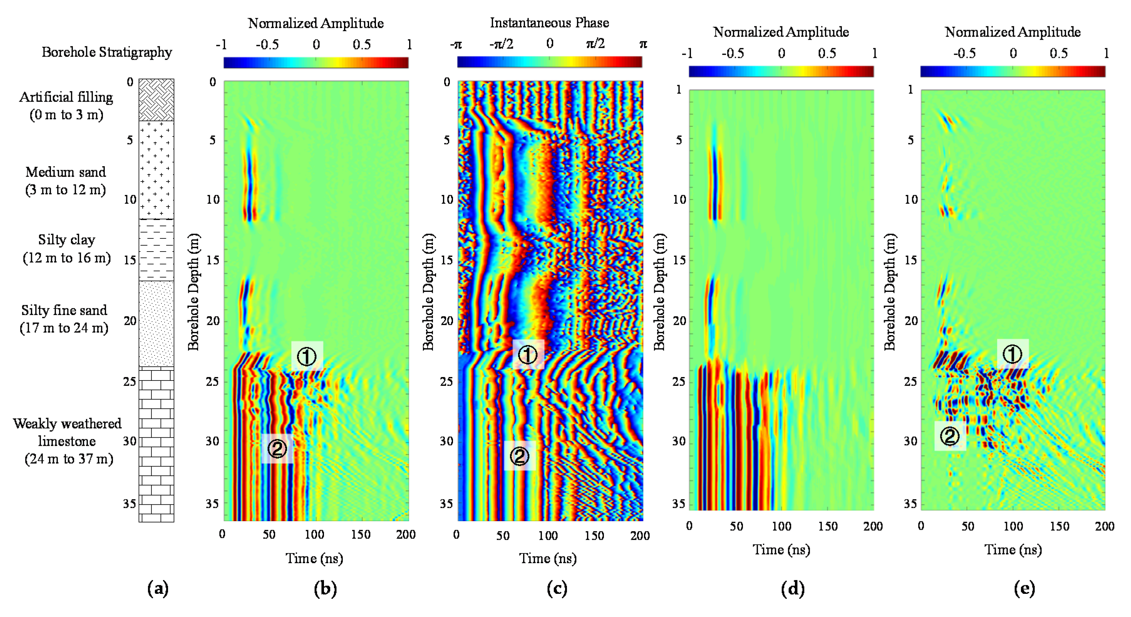
The tested borehole of ZK-4-36 identifies a 3 m thick artificial filling, overlaying 9 m thick medium sand, 4 m silty clay, 7 m thick silty fine sand, and weakly weathered limestone of more than 10 m. The borehole GPR data (Figure 9b) indicate the fast attenuation of EM wave amplitudes in the soil layer. Direct waves in the depth range of sand can be observed, but cannot be seen in the range of clay. The direct waves in the bedrock range arrive earlier than those in the soil layer because of the faster EM wave velocity in limestone. The waveform behind the borehole is generally regular. Some reflection in upper bedrock (Events 1 and 2 in Figure 9b) can be observed but visual identification of the arrival time and event shape is difficult.
In Figure 9c, the direct wave and following waveforms in the silty clay depth range, which is slower than that of sand, can be noted. The instantaneous phase shows that the signal frequency is lower in the soil due to the fast attenuation of high-frequency signals. Median filtered waves in Figure 9e suggest that Event 1 corresponds to the soil–rock interface (24 m deep). The EM wave velocity can be estimated to be 0.114 m/ns based on the slope of the event, which corresponds to the velocity in the weakly weathered limestone. Event 2 indicates a rock linear fracture at a depth of 26 m. There is no visible backscatter at a depth range of 26–36 m. Thus, the bedrock in this depth range is integrated. In the pile construction, the steel casing was lowered to the soil–rock interface (24 m deep).

5. Discussion

Based on the detection interpretation, in this study, a workflow of pile construction is designed and deployed in a freeway bridge extension project. According to the ongoing construction feedback, the remediation of karst voids, the construction methods, and the advantages and disadvantages of the approach are discussed in this section.

5.1. Remediation of Karst Voids

The sinkholes that were identified by the borehole and borehole radar detection were remedied by compaction grouting before pile construction. The compaction grouting injects stiff mortar-like grout under extremely high pressure directly into the ground to displace and fill sinkholes, and compact the surrounding soils. The compaction grout was applied from the soil–rock interface upward until the desired depth (e.g., a depth range of 10–25 m in scenario 2).
Karst voids in the bedrock were remedied during construction. For those karst voids with infill and that were smaller than 4 m, the roofs of the voids were drilled through and artificial construction materials (cement, sodium silicate, crushed stone, and red clay) were deposited, mixed, and compacted in the voids (e.g., 24, 29, and 33 m deep in scenario 1 and 25, 31, and 33 m deep in scenario 2). Slurry grouting was used to prevent leakage and to check the compaction. For those karst voids without infill or that were larger than 4 m, low-grade concrete was filled through a pipe after drilling the roofs of the karst voids. The concrete filling stoped until 0.5 m above the bottom of the steel casing. The piling restarted after the concrete had a certain strength.

5.2. Construction Methods

The single borehole radar detection indicates areas where karst is strongly developed, such as in scenarios 1 and 2. A construction strategy of rotary bored piling with real-time and permanent steel casing was employed in piles where multiple karst voids and sinkholes were detected. The rotary drilling drives the steel casing to push down until reaching complete bedrock and alternates between drilling and excavation (e.g., 35 m in scenario 1, 37 m deep in scenario 2, 20 m deep in scenario 3, and 24 m deep in scenario 4). During piling, the depth of drilling excavation was never allowed to be lower than the bottom of the steel casing.
An enhancement is necessary when the foot blade of the steel casing is lowered to within 2 m of the top of karst voids (e.g., multiple enhancements in scenario 1). Lowering is stopped and the casing is held to prevent sinking caused by the weight of the casing. Three packs of cement and crushed stone are deposited and compacted in stages. The thickness of each deposited filling is 1 m. After multiple stages of filling and compacting, the foot blade of the steel casing can prevent the leakage of drilling slurry and the collapse of the hole. A similar enhancement measure can be employed when the steel casing is close to the uneven floor of karst voids.

5.3. Strengths and Weaknesses of Single Borehole Radar Detection

Compared with seismic-based near-surface geophysical methods, GPR is more sensitive to water or saturated soil geological anomalies. Reflection from karst voids with water infill is more pronounced. The EM waves decay slowly in air, thus karst voids with no infill would not decrease the detection range. Due to pre-existing boreholes at the pile locations, the single borehole GPR detection method saves both time and money. Borehole based detection provides better detection accuracy and resolution since the detection is conducted closer to the geological object. Meanwhile, the proposed rapid data processing method combining instantaneous phase analysis and medium filtering can effectively extract and highlight weak karst voids reflection from borehole background noise in the near-offset borehole radar detection.
However, some limitations of the single borehole radar detection nonetheless exist and need to be studied in the future. (1) There is a lack of azimuth information. Azimuthal single borehole radar was previously developed to determine the azimuth of an object, but its application has been rarely reported. The azimuth of karst voids at the pile location does not affect the determination of the pile depth, but is critical to remediation. (2) In the proposed method, a PVC tube is used to protect the borehole from collapse. However, debris sediment at the bottom of the borehole and at the roof and floor of karst voids makes it difficult to push the PVC down to the bottom, which decreases detection depth range. (3) The detection result is not as intuitive as cross-hole tomography. Full waveform inversion is recommended to invert single borehole radar data.

6. Conclusions

In this paper, we employ a single borehole radar detection system to investigate geological anomalies at pile locations. The detection was tested in a controlled horizontal borehole setup and then applied in a freeway bridge extension project located in an urban karst area. The following conclusions can be drawn:
  • Karst geological anomalies significantly affect the bearing capacity and construction of piles. To detect karst voids at pile locations, a single borehole GPR prototype with a near offset (30 cm) and a small diameter (36 mm) was developed for engineering application of imaging karst anomalies with high resolution. Instantaneous phase analysis by Hilbert transform was employed as an effective way to make low energy reflection visible, and medium filtering was used to differentiate weak reflection from borehole background noise.
  • A controlled single borehole GPR experiment was conducted in a mining horizontal borehole to demonstrate the applicability of the prototype and the advantages of the signal analysis methods. The experiment results show three typical reflection events in the detection of karst anomalies at pile locations: (a) a linear event intersecting a borehole corresponds to a soil–rock interface or rock fracture that crosses the borehole; (b) a linear event outside a borehole corresponds to a linear rock fracture outside the borehole; and (c) a hyperbolic reflection indicates point sharped karst voids or sinkholes.
  • Single borehole GPR detection was applied in a freeway bridge extension project located in an urban karst area. The results show that the high-frequency signal decays rapidly in the soil and at the infill depth range of karst voids. The direct EM wave event is discontinued and irregular in the depth range of weathered rock. The EM wave velocity can be identified based on the slope of the linear fracture crossing the borehole. The location of the surrounding karst voids can be estimated by the velocity and arrival time of the hyperbolic reflection. Phase reversal can be observed if the void is filled by water or saturated soil.
  • Borehole reverberation of noise signals inside the borehole was observed in the detection of a sinkhole. Band-pass filtering was applied to remove the high-frequency ringing noise. The velocity estimation can be used to determine if the event real diffraction or an artifact. The identification of a sinkhole needs to consider the geological setting of the upper bedrock. If there is a karst void beneath a weathered and fractured upper bedrock layer, the enlargement of the borehole in the soil range likely suggests soil loss and a developing sinkhole.
  • The remediation of karst voids and the construction method of piles were designed based on the investigation results. Potential sinkholes were remedied by compaction grouting before the pile construction. A construction strategy of rotary bored piling with real-time and permanent steel casing was employed in the piles where multiple karst voids and sinkholes were identified. The construction feedback demonstrates that single borehole radar detection is effective for the investigation of anomalies at pile locations in urban karst areas.

Author Contributions

Conceptualization, L.L.; methodology, Z.S.; software, M.P.; validation, G.P.T. and L.L.; formal analysis, L.L.; investigation, L.L.; resources, Z.S. and M.P.; data curation, M.P.; visualization, L.L. writing—original draft, L.L.; writing—review and editing, Z.S. All authors have read and agreed to the published version of the manuscript.

Funding

The research in this paper was supported by the National Natural Science Foundation of China (Nos. 41731283 and 41877234), the Fundamental Research Funds for the Central Universities (No. 22120180538), the Tongji University Civil Engineering Peak Subject International First-class Research Cooperation Fund (No. 2019010201), and the National Basic Research Program of China-Program 973 (No. 2013CB036404).

Acknowledgments

Special thanks are owed to the Wuhan Changsheng Engineering Exploration Technology Development Co., Ltd., and Qiang Wu and Yifan Zeng at the China University of Mining and Technology for the joint development of the borehole radar system.

Conflicts of Interest

The authors declare no conflict of interest.

References

  1. Li, S. The Theory and Method of Geological Prediction for the Disaster Source of Water and Mud Inrush in Tunnels; China Science Publishing: Beijing, China, 2015. [Google Scholar]
  2. Li, S.; Liu, B.; Sun, H.; Nie, L.; Zhong, S.; Su, M.; Li, X.; Xu, Z. State of art and trends of advanced geological prediction in tunnel construction. Chin. J. Rock Mech. Eng. 2014, 33, 1090–1113. [Google Scholar]
  3. Li, S.; Liu, B.; Xu, X.; Nie, L.; Liu, Z.; Song, J.; Sun, H.; Chen, L.; Fan, K. An overview of ahead geological prospecting in tunneling. Tunnel. Undergr. Space Technol. 2017, 63, 69–94. [Google Scholar] [CrossRef]
  4. Jiang, X.; Xiao, R.; Zhang, M.; Hu, W.; Bai, Y.; Huang, B. A laboratory investigation of steel to fly ash-based geopolymer paste bonding behavior after exposure to elevated temperatures. Constr. Build. Mater. 2020, 254, 119267. [Google Scholar] [CrossRef]
  5. Shen, D.; Shi, Z.; Peng, M.; Zhang, L.M.; Jiang, M. Longevity analysis of landslide dams. Landslides 2020. [Google Scholar] [CrossRef]
  6. Zajc, M.; Celarc, B.; Gosar, A. Structural-geological and karst feature investigations of the limestone-flysch thrust-fault contact using low-frequency ground penetrating radar (Adria-Dinarides thrust zone, SW Slovenia). Environ. Earth Sci. 2015, 73, 1–13. [Google Scholar] [CrossRef]
  7. Angelis, D.; Tsourlos, P.; Tsokas, G.; Vargemezis, G.; Zacharopoulou, G.; Power, C. Combined application of GPR and ERT for the assessment of a wall structure at the Heptapyrgion fortress (Thessaloniki, Greece). J. Appl. Geophys. 2018, 152, 208–220. [Google Scholar] [CrossRef]
  8. Xia, J. Estimation of near-surface shear-wave velocities and quality factors using multichannel analysis of surface-wave methods. J. Appl. Geophys. 2014, 103, 140–151. [Google Scholar] [CrossRef]
  9. Ivanov, J.; Miller, R.D.; Lacombe, P.; Johnson, C.D.; Lane, J.W. Delineating a shallow fault zone and dipping bedrock strata using multichannal analysis of surface waves with a land streamer. Geophysics 2006, 71, A39–A42. [Google Scholar] [CrossRef] [Green Version]
  10. Liu, B.; Liu, Z.; Li, S.; Fan, K.; Nie, L.; Zhang, X. An improved Time-Lapse resistivity tomography to monitor and estimate the impact on the groundwater system induced by tunnel excavation. Tunnel. Undergr. Space Technol. 2017, 66, 107–120. [Google Scholar] [CrossRef]
  11. Liu, B.; Liu, Z.; Li, S.; Nie, L.; Su, M.; Sun, H.; Fan, K.; Zhang, K.; Pang, Y. Comprehensive surface geophysical investigation of karst caves ahead of the tunnel face: A case study in the Xiaoheyan section of the water supply project from Songhua River, Jilin, China. J. Appl. Geophys. 2017, 144, 37–49. [Google Scholar]
  12. Sun, H.; Li, X.; Li, S.; Qi, Z.; Su, M.; Xue, Y. Multi-component and multi-array TEM detection in karst tunnels. J. Geophys. Eng. 2012, 9, 359–373. [Google Scholar] [CrossRef]
  13. Li, S.; Sun, H.; Lu, X.S.; Li, X. Three-dimensional modeling of transient electromagnetic responses of water-bearing structures in front of a tunnel face. J. Environ. Eng. Geophys. 2014, 19, 13–32. [Google Scholar] [CrossRef]
  14. Tran, K.T.; McVay, M.; Faraone, M.; Horhota, D. Sinkhole detection using 2D full seismic waveform tomography Sinkhole detection by FWI. Geophysics 2013, 78, R175–R183. [Google Scholar] [CrossRef]
  15. Steeples, D.; Knapp, R.; McElwee, C. Seismic reflection investigations of sinkholes beneath Interstate Highway 70 in Kansas. Geophysics 1986, 51, 295–301. [Google Scholar] [CrossRef] [Green Version]
  16. Hiltunen, D.; Cramer, B. Application of seismic refraction tomography in karst terrane. J. Geotech. Geoenviron. Eng. 2008, 134, 938–948. [Google Scholar] [CrossRef]
  17. Liu, L.; Shi, Z.; Peng, M.; Liu, C.; Tao, F.; Liu, C. Numerical modeling for karst cavity sonar detection beneath bored cast in situ pile using 3D staggered grid finite difference method. Tunn. Undergr. Space. Tech. 2018, 82, 50–65. [Google Scholar] [CrossRef]
  18. Musil, M.; Maurer, H.R.; Green, A.G. Discrete tomography and joint inversion for loosely connected or unconnected physical properties: Application to crosshole seismic and georadar data sets. Geophys. J. Int. 2003, 153, 389–402. [Google Scholar] [CrossRef] [Green Version]
  19. Liu, L.; Shi, Z.; Peng, M.; Tsoflias, G.P.; Liu, C.; Tao, F.; Liu, C.S. A borehole multifrequency acoustic wave system for karst detection near piles. J. Appl. Geophys. 2020, 177, 104051. [Google Scholar] [CrossRef]
  20. Zhong, S.; Wang, C.; Wu, L.; Wu, Y.H.; Wang, Q.Y. Borehole radar response characteristics of point unfavorable geo-bodies: Forward simulation on its geometric effect. Rock Soil Mech. 2011, 32, 1583–1588. [Google Scholar]
  21. Zhong, S.; Wang, C.; Wu, L.; Tang, X.; Wang, Q. Borehole radar response characteristics of point unfavorable geo-bodies: Forward simulation of its surrounding rock and filling condition. Rock Soil Mech. 2012, 33, 1191–1195. [Google Scholar]
  22. Ma, C.; Zhao, Q.; Ran, L.; Chang, X. Numerical Study of Borehole Radar for Cliff Imaging. J. Environ. Eng. Geophys. 2014, 19, 269–276. [Google Scholar] [CrossRef]
  23. Ma, C.; Zhao, Q.; Wang, L.; Liu, S. Modeling borehole radar by finite-difference time-domain in conductive sandstone. J. Environ. Eng. Geophys. 2015, 20, 19–29. [Google Scholar] [CrossRef]
  24. Ebihara, S. Directional borehole radar with dipole antenna array using optical modulators. IEEE Trans. Geosci. Remote Sens. 2004, 42, 45–58. [Google Scholar] [CrossRef]
  25. Qin, H.; Vrugt, J.; Xie, X.; Zhou, Y. Improved characterization of underground structure defects from two-stage Bayesian inversion using crosshole GPR data. Automa. Constr. 2018, 95, 233–244. [Google Scholar] [CrossRef] [Green Version]
  26. Liu, B.; Zhang, F.; Li, S.; Liu, L.; Li, Y.; Xu, X.; Liu, Z.; Zhang, Q. Full waveform inversion based on inequality constraint for cross-hole radar. J. Appli. Geophys. 2019, 162, 118–127. [Google Scholar] [CrossRef]
  27. Li, Y.; L, S.; Liu, B.; Nie, L.; Zhang, F.; Xu, L.; Wang, C. Forward simulation and complex signal analysis of borehole radar detection for underground adverse geological bodies. Rock Soil Mech. 2017, 38, 300–308. [Google Scholar]
  28. Alperovich, L.; Eppelbaum, L.; Zheludev, V.; Dumoulin, J.; Soldovieri, F.; Proto, M.; Proto, M.; Loperte, A. A new combined wavelet methodology applied to GPR and ERT data in the Montagnole experiment (French Alps). J. Geophys. Eng. 2013, 14, 1–17. [Google Scholar]
  29. Taner, M.; Koehler, F.; Sheriff, R. Complex seismic trace analysis. Geophysics 1979, 44, 1041–1063. [Google Scholar] [CrossRef]
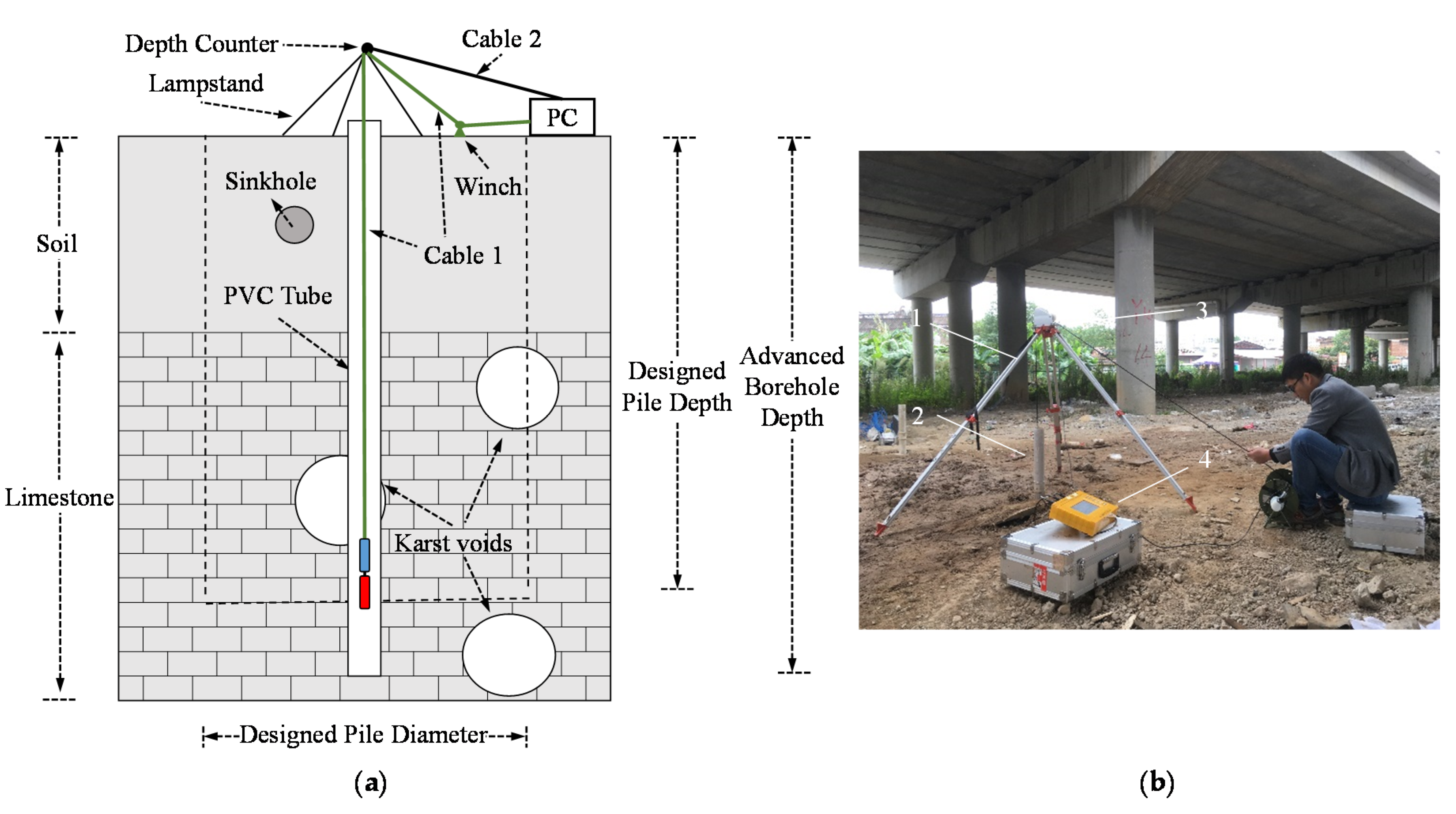
Figure 1. (a) Schematic diagram of the single borehole detection deployed in a borehole at pile location. Multiple karst voids are shown in the designed pile outlined by a dashed line. (b) Single borehole test in the field. PVC casing is placed in the borehole to avoid borehole collapse and shrinkage. 1—lampstand, 2—borehole with PVC casing, 3—Depth counter, 4—PC.
Geosciences 10 00232 g001
Figure 2. The single borehole ground penetration radar (GPR) prototype system. 1—computer, 2—transmitting antenna, 3—receiving antenna, 4—fiber cable, 5—depth counter, 6—charger.
Geosciences 10 00232 g002
Figure 3. Geometry setup of controlled single borehole GPR test. AB, AC, CE, and EO separation is 7.5, 2.8, 19.0, and 5.4 m, respectively, according to the roadway design. AD, BD, and DO separation can be calculated as 7.28, 1.81, and 19.12 m, respectively.
Geosciences 10 00232 g003
Figure 4. Original single borehole GPR detection data of controlled horizontal borehole experiment: (a) processed radar data; (b) instantaneous phase; (c) removed wave profile using median filtering; (d) median filtered wave. Two meters at the top and bottom are removed during median filtering.
Geosciences 10 00232 g004
Figure 5. Schematic of the freeway extension project. (a) Simplified stratigraphy of the freeway extension bridge project. A new bridge will be built immediately adjacent to the old bridge; (b) field site before and during construction.
Geosciences 10 00232 g005
Figure 6. Single borehole GPR detection data for a typical karst void borehole scenario. (a) No. ZK-4-11 borehole stratigraphy; (b) radar data; (c) instantaneous phase; (d) removed wave profile using median filtering; (e) median filtered wave.
Geosciences 10 00232 g006
Figure 7. Single borehole GPR detection data on a typical karst void borehole scenario. (a) No. ZK-2-23 borehole stratigraphy; (b) original radar data; (c) instantaneous phase; (d) removed wave profile using median filtering; (e) median filtered wave; (f) Low-pass filtered radar data; (g) instantaneous phase of low-pass filtered radar data; (h) median filtering removed wave profile of low-pass filtered data; (i) median filtered wave of low-pass filtered data.
Geosciences 10 00232 g007
Figure 8. Single borehole GPR detection data on a typical rock fracture borehole scenario. (a) No. ZK-7-13 borehole stratigraphy; (b) radar data; (c) instantaneous phase; (d) removed wave profile using median filtering; (e) median filtered wave.
Geosciences 10 00232 g008
Figure 9. Single borehole GPR detection data on a typical rock fracture borehole scenario. (a) No. ZK-4-36 borehole stratigraphy; (b) radar data; (c) instantaneous phase; (d) removed wave profile using median filtering; (e) median filtered wave.
Geosciences 10 00232 g009