Article

Timing, Mechanics and Controls of the Evolution of the Southernmost Part of the Oman Mountains: The Salakh Arch

by
Mohammed H. N. Al-Kindi
Earth Sciences Consultancy Centre, P.C. 611, P.O.Box 979 Muscat, Oman
Geosciences 2020, 10(3), 95; https://doi.org/10.3390/geosciences10030095
Submission received: 20 December 2019 / Revised: 8 February 2020 / Accepted: 24 February 2020 / Published: 1 March 2020
(This article belongs to the Special Issue Tectonics of Oman—from the Precambrian to the Present)

Abstract

:
Regional surface and subsurface mapping of the front range of the Oman Mountains, Salakh Arch’s fold-and-thrust belt, is conducted to understand the timing and nature of its deformation and to analyze the main controls on its position, geometry and evolution. The results from this study can be applied to other fold-and-thrust belts, as the area offers surface and subsurface datasets that allow good understanding of its evolution history. The deformation of the outcropping Middle Miocene to Pliocene deposits and the displacement of the Cenozoic seismic reflections imply that folding and thrusting was active during the Neogene and possibly ceased during the Early Quaternary. The palaeostress-tensor analyses from the kinematic fault data along with the fold-axes trends show that the regional transport direction was, overall, directed to the south. Lateral movements over oblique or lateral ramps, between the frontal ramps, have caused local deflections of the regional stress trajectories. The shortening values measured from restored seismic sections were utilized to restore the arch in map view. The restoration indicates that the arch initiated as a primary arc right from the start of deformation. As the shortening proceeded, clockwise and anticlockwise rotations occurred in some areas as a consequence of displacement gradients across adjacent areas along the arch. This rotation was most likely accommodated by angular shear strain, which results in arch-parallel extension or transtension. Various factors have controlled the position, geometry and segmentation of the fold segments in the Salakh Arch. The folds that developed in areas of thicker deformed sediments are wider and more uplifted and advanced to the foreland than the folds that develop in thin deformed sediments. Pre-existing faults were reactivated as lateral and frontal ramps during the arch’s evolution. They have contributed in the location and segmentation of the fold patches. On the other hand, the depth-to-detachment measurements and restoration results suggest that the folds detach along the Ediacaran-Early Cambrian Ara Salt. Overall, the deformation in the Salakh Arch could be described as an interaction between thin- and thick-skinned tectonics.

1. Study Area

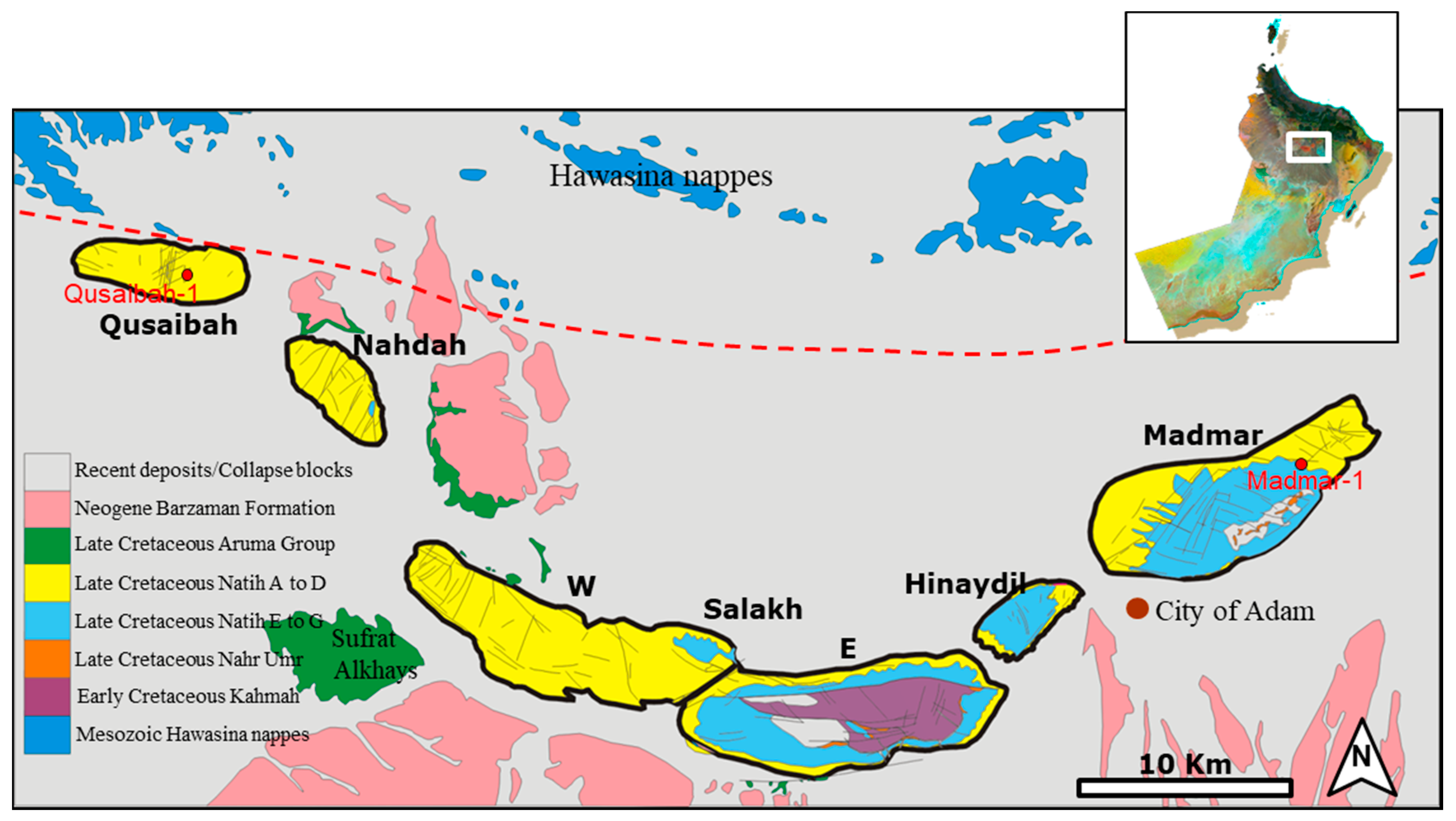
The Salakh Arch (Figure 1) represents the front range of the Oman Mountains. It developed in the eastern margin of Fahud Salt Basin, S of the Hawasina nappes and NE of the Maradi Fault Zone, to form what is known as the Adam Foothills. The arch is often called the Salakh Arc, instead of arch. The area is approximately 40 km NE of the hydrocarbon-producing Natih and Fahud fields. The Salakh Arch is composed of six doubly-plunging anticlines. These anticlines from E to W are: Madmar, Hinaydil, Salakh E, Salakh W, Nahdah, and Qusaibah (Figure 2). The Salakh structure forms the middle part of the Salakh Arch. It is divided into two parts: Salakh E and Salakh W, which are considered here as independent anticlines. These parts differ significantly in their geometries and are separated by a distinct saddle.
The fold-and-thrust belt (FTB) of the Salakh Arch is concave towards the north, with a strike-length of 75 km and a maximum height in Jebel Salakh E of 1063 m. The area was explored for hydrocarbon accumulation. Qusaibah-1 and Madmar-1 wells (Figure 2) were drilled in 1969 and the mid 1980s respectively [1,2]. The drilling tests were unsuccessful. Nonetheless, the area has remained an attraction for the hydrocarbon industry as it forms a good stratigraphical and structural analogue to the hydrocarbon fields in the foreland region. Recently, there has been more interest to re-explore the area for hydrocarbon accumulations, particularly for deep-gas exploration, which targets the Early Palaeozoic siliciclastic deposits.
This work aims to correlate surface and subsurface data in the Salakh Arch to understand its evolution history and the main controls on its geometry and structural features. The findings from this study and their results may have general applicability to the investigations of fold-and-thrust belts in other areas. This study also offers an opportunity to better understand the Late Cretaceous and Cenozoic tectonics in Oman and the region.

2. Geological Setting

The Oman Mountains are the result of two major orogenies, the Early Alpine (Late Cretaceous) and the Late Alpine (Cenozoic) deformations [3].

2.1. Tectonics during the Late Cretaceous

At the beginning of the Late Cretaceous, the Neo-Tethyan Ocean, now partly represented by the Sea of Oman (locations are shown in Figure 3) and the eastern Mediterranean, started to close during the opening of the South Atlantic Ocean [4]. This compression event led to the development of a NE-dipping subduction zone [5] (Figure 3), above which a spreading centre produced an oceanic crust that became the Semail Ophiolite. The subduction zone approached the Arabian margin as the oceanic crust, which was attached to Arabia, was consumed beneath it [6]. A significant volume of the Mesozoic continental slope and the deep oceanic sediments (the Hawasina Complex) along with the adjacent (Cenomanian) Tethyan oceanic crust (the Semail Ophiolite) were eventually obducted over the eastern margin of the Arabian Platform [7,8]. The Hawasina Supergroup was successively accreted to the hanging wall of the subduction zone as a series of thrust slices beneath, and extending ahead of, the ophiolite. The Hawasina Supergroup and the Semail Ophiolite were then obducted onto the Arabian margin during the Santonian-Campanian as a product of attempted subduction of the leading edge of the continental margin.
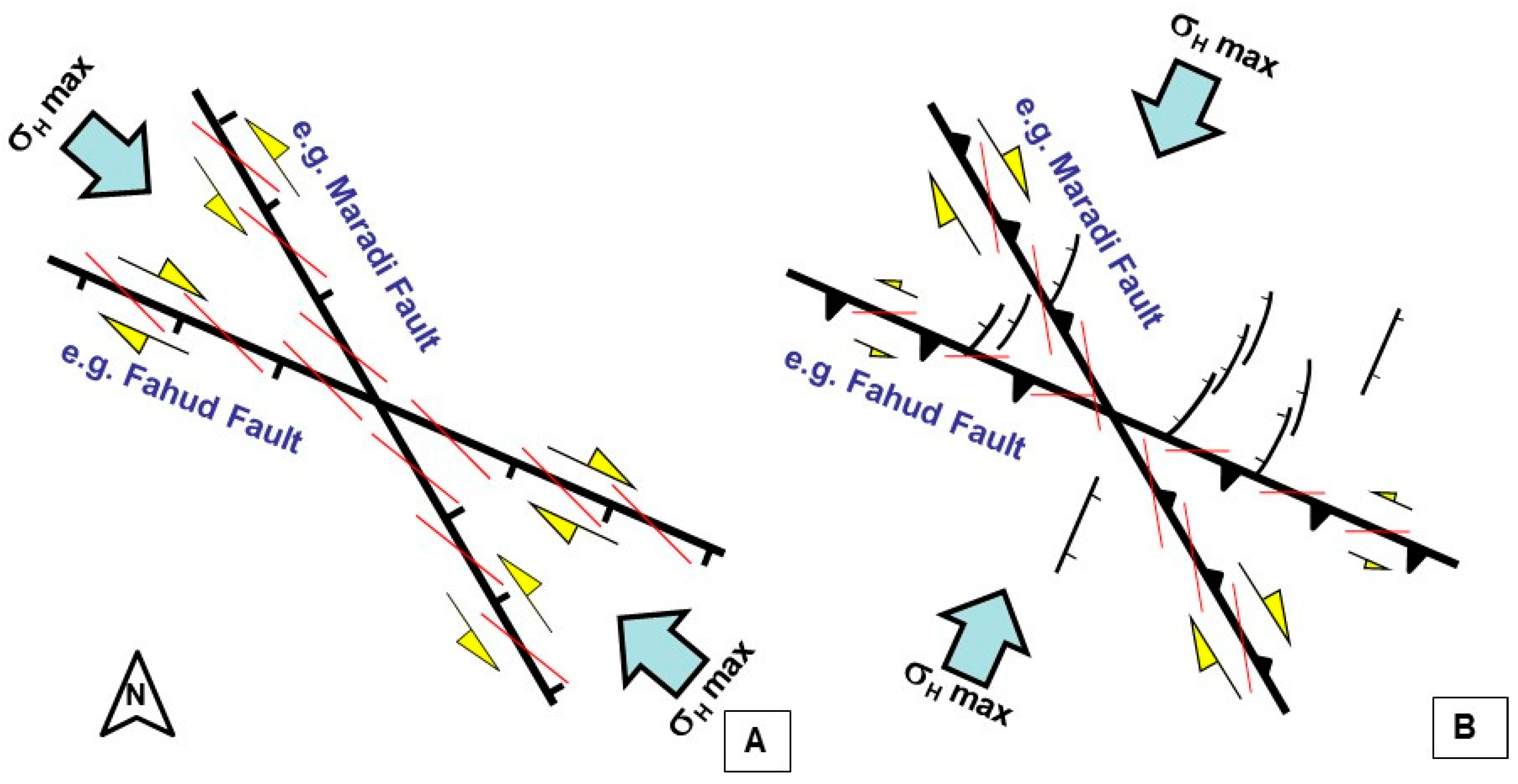
Because of the loading on the Arabian Platform, a foredeep (the Aruma basin) developed rapidly south of the advancing thin-skinned thrust sheets of the allochthonous units [10]. Filbrandt et al. [11] have also added that the maximum horizontal compressive stress south of the Oman Mountains was oriented NW-SE during Late Santonian and Campanian and possibly into the Early Cenozoic. This stress regime produced transtensional faults in the foreland region of Oman Mountains that fall into two sets: 100–110° and 130–160°. The Maradi and Fahud fault systems were initiated or at least reactivated during that time [3] (Figure 4). Filbrandt et al. [11] related this compression to the collision of the Indian–Afghan Subcontinent with the Arabian Plate during the Santonian to Campanian, which also initiated a zone of sinistral transpression along the eastern margin of Oman, as in [12].

2.2. Tectonics during Cenozoic

The overprint and timing of the Late Alpine deformation in Oman is not well defined. Several studies and models interpreted the evolution of the Oman Mountains as a result of the Cenozoic compressional regimes, which are primarily related to the separation of the Arabian Plate from Africa along the Red Sea spreading zone and its subsequent northeastern movement and collision with the Eurasian Plate, as in e.g., [7,13]. According to Loosveld et al. [12], the Oman Mountains were broadly uplifted during the Cenozoic in a completion of the mountain building process. In the Eocene-Pliocene, the Salakh Arch formed, the Fahud main fault was reactivated with a small sinistral component, and many normal faults, including the main Natih Field fault, were inverted to reverse faults. The foreland deformation and uplift of what they identified as the central Oman Mountains is a consequence of the Arabian Platform collision with the Iranian crustal collage and its subsequent southward-directed transpression and inversion of the earlier rift margin [13,14]. Moreover, Fournier et al. [15] concluded that the compression was initiated in northern Oman possibly as early as the Late Oligocene, coeval with the start of the Arabia–Eurasia collision along the Zagros Mountains.
Hanna and Nolan [6] also marked a Late Neogene (Plio-Pleistocene) reactivation of the Maradi Fault Zone as a dextral transtensional fault. Carbon [16], however, argued that the location, geometry and kinematics of the Neogene tectonics and structures suggest that the recent and still active deformations are associated with the rejuvenation of the SW-verging Late-Cretaceous obduction-related structures, i.e., the Neogene tectonic in northern Oman is not linked to the collision of the Musandam Peninsula and Iran as previously proposed by, for example, Boote et al. [17].
On the other extreme, Hanna [18] described the overprint of the Late Alpine deformation in the central Oman Mountains as weak. Mann et al. [19] further commented that during the Late Campanian to Cenozoic there is evidence of only localized compression during the overall extensional regime. This local compression might have produced the present high structural relief by post-Palaeogene uplift. According to them, this implies that the Cenozoic compression, which is identified in the Musandam Peninsula, dies out to the SE away from the central Oman Mountains. In general, they concluded that there is no mid-Cenozoic compressional regime in the central Oman Mountains [20]. Furthermore, Hanna and Smewing [6] suggested that the Salakh Arch formed during the Late Cretaceous in support of Hanna’s [18] model, which interpreted the internal and external structures of the Oman Mountains, as far as Jebel Madmar in Salakh Arch, to be related to emergent thin-skinned thrusts that formed during Late Cretaceous subsequent to ophiolite obduction. Al-Lazki et al. [21] has supported this evolution time and interpreted the Qusaibah structure as a Late-Cretaceous negative flower structure bounded by transtensional faults.
Al-Wardi and Butler [22] interpreted the Oman Mountains (i.e., the internal zone: Saih Hatat and Jebel Akhdar massifs) as Late-Cretaceous orogenic belts that post-date ophiolite obduction. Yet, Mount et al. [19] proposed that the Saih Hatat and Jebel Akhdar anticlines, along with Salakh Arch, are related to compressional thick-skinned tectonics created in the Late Palaeogene. Using apatite fission track performed on a granite cobble from Jebel Akhdar, they proposed that the last phase of compressional deformation was constrained to be Oligocene; this was then followed by slower Neogene cooling [19]. Breton et al. [23] have also related the present domal shape of Jebel Akhdar to the Cenozoic tectonic events.

2.3. Stratigraphy of the Study Area

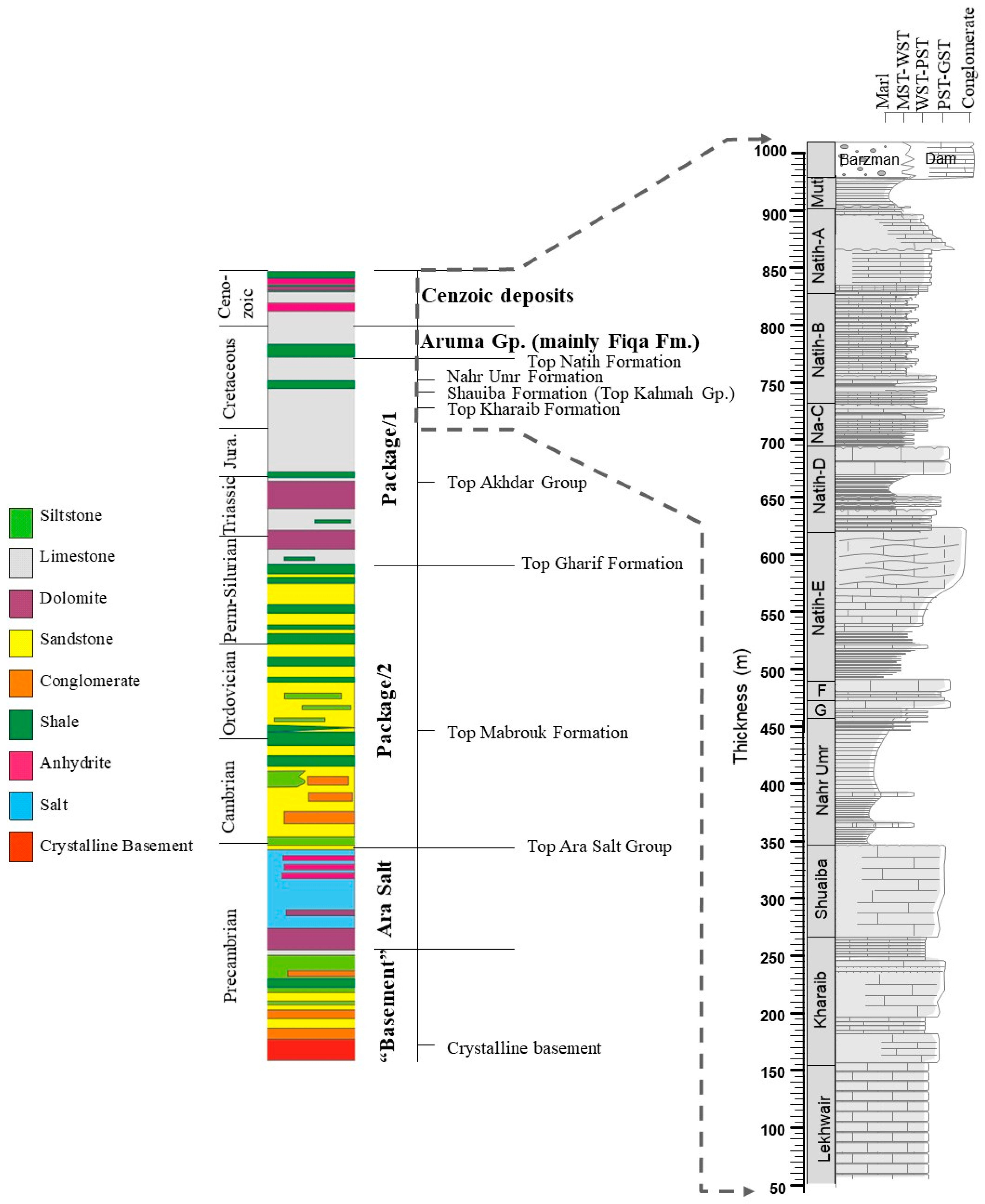
The outcrops in the Salakh Arch belong to the Cretaceous carbonate platform. The Natih Formation forms the majority of the exposures in all jebels (Figure 5). It is subdivided into seven members, known as Natih-G to Natih-A in ascending stratigraphic order. Whereas the shale units of the underlying Nahr Umr Shale crop out in Jebel Salakh E and Jebel Madmar, the carbonate formations of the Kahmah Group beneath the Nahr Umr Formation (Shuaiba to Lekhwair formations) are only seen in the Salakh E anticline (Figure 2). The surrounding plain of the jebels is covered by the thin shale units of the Aruma Group and the alluvium of the Barzaman and overlying Quaternary deposits, as well as the collapse from the piedmont of the jebels, as illustrated in Figure 2.
The subsurface stratigraphic column in Oman is simplified here to five main mechanical parts (Figure 5). The Aruma and Tertiary deposits are composed of shallow-marine limestone, shale, marl and evaporites, which define the uppermost relatively weak mechanical unit. Package/1 mainly consists of thick-bedded competent limestone with massive dolomite units at the Top Akhdar Group. Shale beds of Nahr Umr formation exist just below Natih formation. Package/2 is relatively incompetent as it is composed of alternations between sandstone and shale units. The package also includes conglomerate and siltstone layers. The underlying Ara Salt package is also composed of a variety of lithologies such as dolomite and limestone. It forms the weakest ductile package in the column. The basement in this work is considered to be all the units below the Ara Salt including the crystalline basement rocks.

3. Methods

3.1. Surface Data

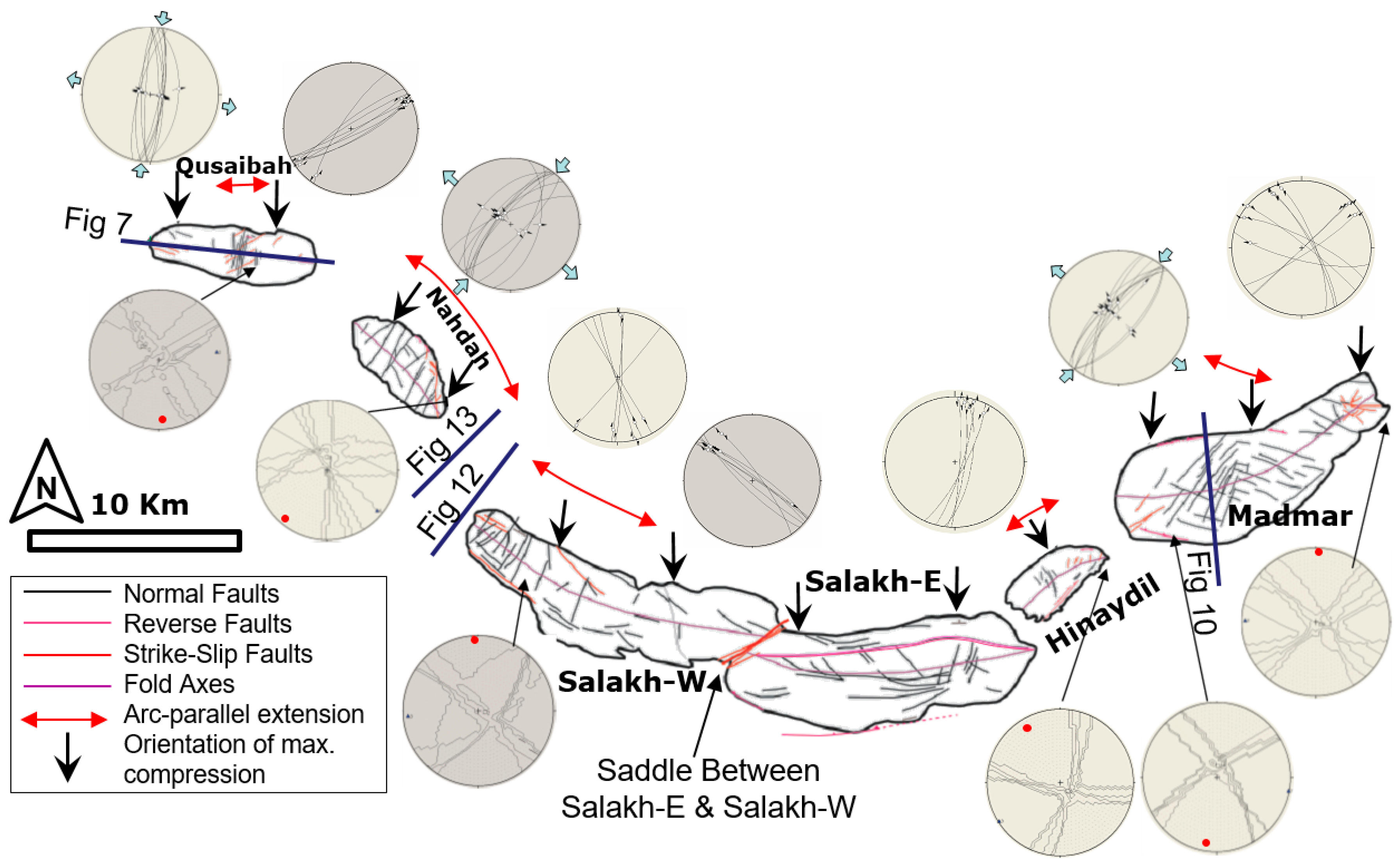
Successive fieldwork sessions were conducted in the study area to map the geometry of the Salakh-Arch segments and their associated structures. The collected fault data include the measurements of strike and dip of the planes and the plunge and azimuth for the associated linear fabrics. The planes are represented as great circles in the lower-hemisphere projection and the lineations as small arrows within the circle (Figure 6). The orientation of the arrow indicates the plunge direction, and its centre represents the plunge. The representation of the data and the paleostress analyses were performed in TectonicsFP software [24]. The software is a free software released under the GNU/GPL License and written by Franz Reiter and Peter Acs. The Right Dihedral method [25] is applied to these data to evaluate the orientations of paleostresses in various parts of the arch.

3.2. Seismic Data

The data used in this chapter primarily includes regional 2-D seismic sections. Several lines are available in the foreland region but few in the hinterland. None of the sections were acquired in the surface exposures of the Salakh Arch. The seismic interpretation of the stratigraphic intervals is confirmed from many wells in the central part of Oman including a few wells from the Natih and Fahud fields. The positions of the reflections of the Mesozoic carbonates (package/1), as shown in Figure 5, are easy to identify in most areas; however, the reflections of the deeper Palaeozoic siliciclastic reflections in the anticlinal cores are unclear in many seismic sections. Therefore, these horizons were commonly constructed by assuming a constant thickness from the carbonate units as in the foreland or the hinterland areas. The basement reflectors are in general difficult to locate as the quality of seismic reflections decreases with depth.

4. Results from Surface Data

The fold structures in the Salakh Arch have two plunges, two flanks, two hinges, and a more-or-less flat crest. This setting is generally consistent with box-fold geometries. The surface data of the Salakh Arch includes measurements of the properties of faults, folds, fractures, and palaeostress indicators. These measurements are summarized in Figure 6. The fold axes are estimated from field data and satellite images. They generally represent the middle crestal lines between the two hinges in each fold structure of the Salakh Arch.

4.1. Qusaibah

Jebel Qusaibah is situated in the western part of Salakh Arch (Figure 2 and Figure 6). Several normal faults (N-S strike) with pure dip-slip movements developed perpendicularly to the fold axis of the crestal area of the structure (Figure 7). The faults form a series of horsts and grabens with a maximum throw of around 80 m. NE-striking strike-slip faults developed in Jebel Qusaibah, particularly in the middle and eastern parts. The palaeostress analysis of kinematic fault data indicates that the maximum stress direction (σ-1) has a N-S strike. Other extensional faults in Jebel Qusaibah include a few WNW-ESE faults that are spread in various places, particularly the western plunge, and a small E-W back thrust in the northern flank (Figure 2 and Figure 6). The WNW-ESE faults are often cut by the NE-SW strike-slip faults and the N-S extensional faults.

4.2. Nahdah

The axis of the Nahdah structure slightly curves from N50° W in the northern part to N33° W in the southern side (Figure 2 and Figure 6). Normal faults perpendicular to the fold axis form throughout the structure with throws ranging from 10 to 100 m. Major strike-slip faults are distinctively abundant in the southeastern side of the northeastern limb. They mainly trend NNW-SSE or N-S, and the orientation of σ-1 is NE-SW with the minimum stress direction (σ-3) trending parallel to the fold axis, according to the palaeostress analysis that were obtained from these faults (Figure 6). A few reverse faults occur in the northeastern limb of Nahdah.

4.3. Jebel Salakh W

The Salakh W anticline is characterized by extension parallel to the fold axis (Figure 6), which is manifested by NNE-SSW cross normal faults that form horst and graben structures (Figure 8B). These faults developed in the western side of the fold and diminish towards the eastern side. Several strike-slip faults formed in Salakh W. They trend NW-SE and include different senses of fault kinematics with mainly oblique striations of around 25° plunge.

4.4. The Saddle between Salakh E and Salakh W

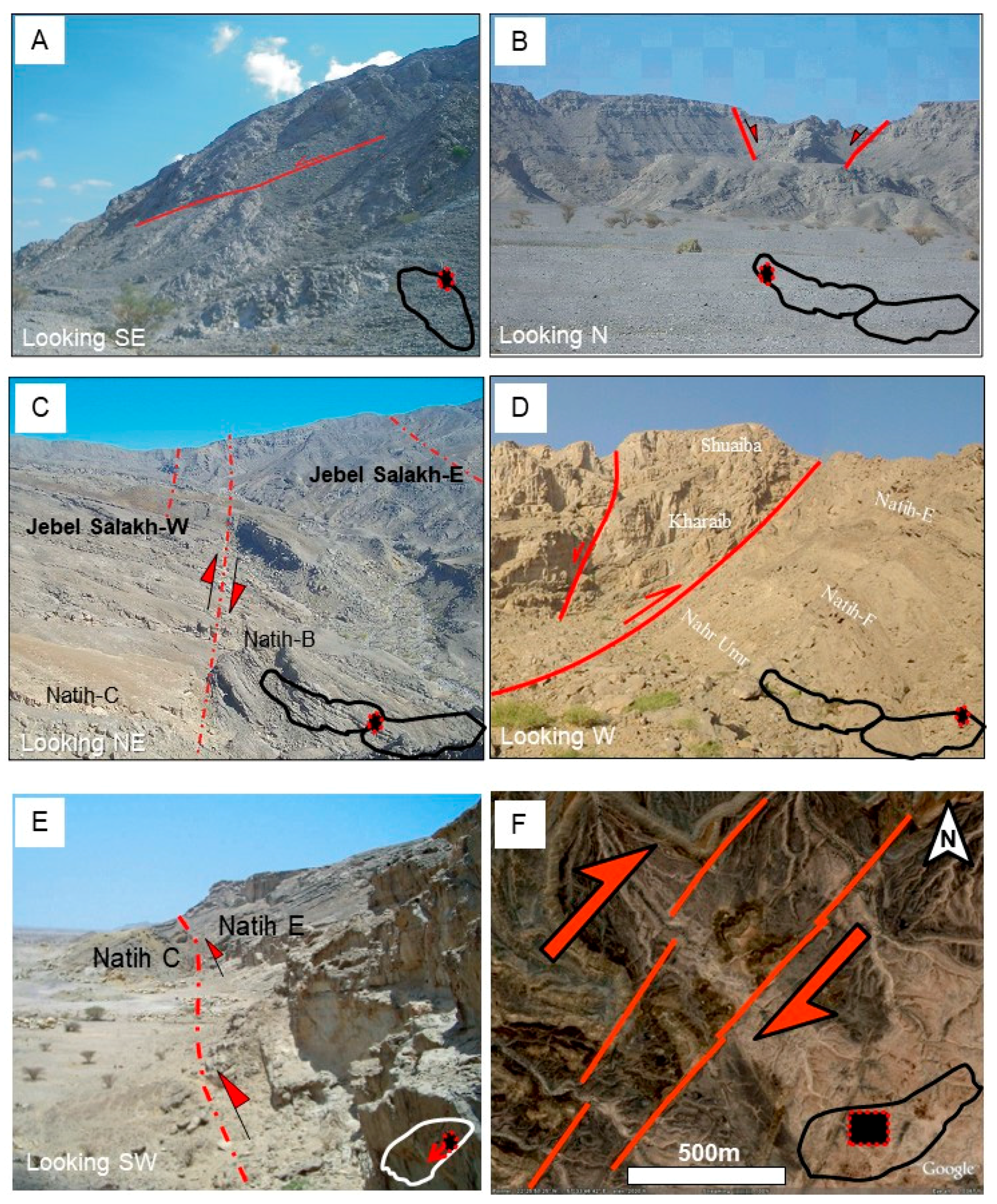
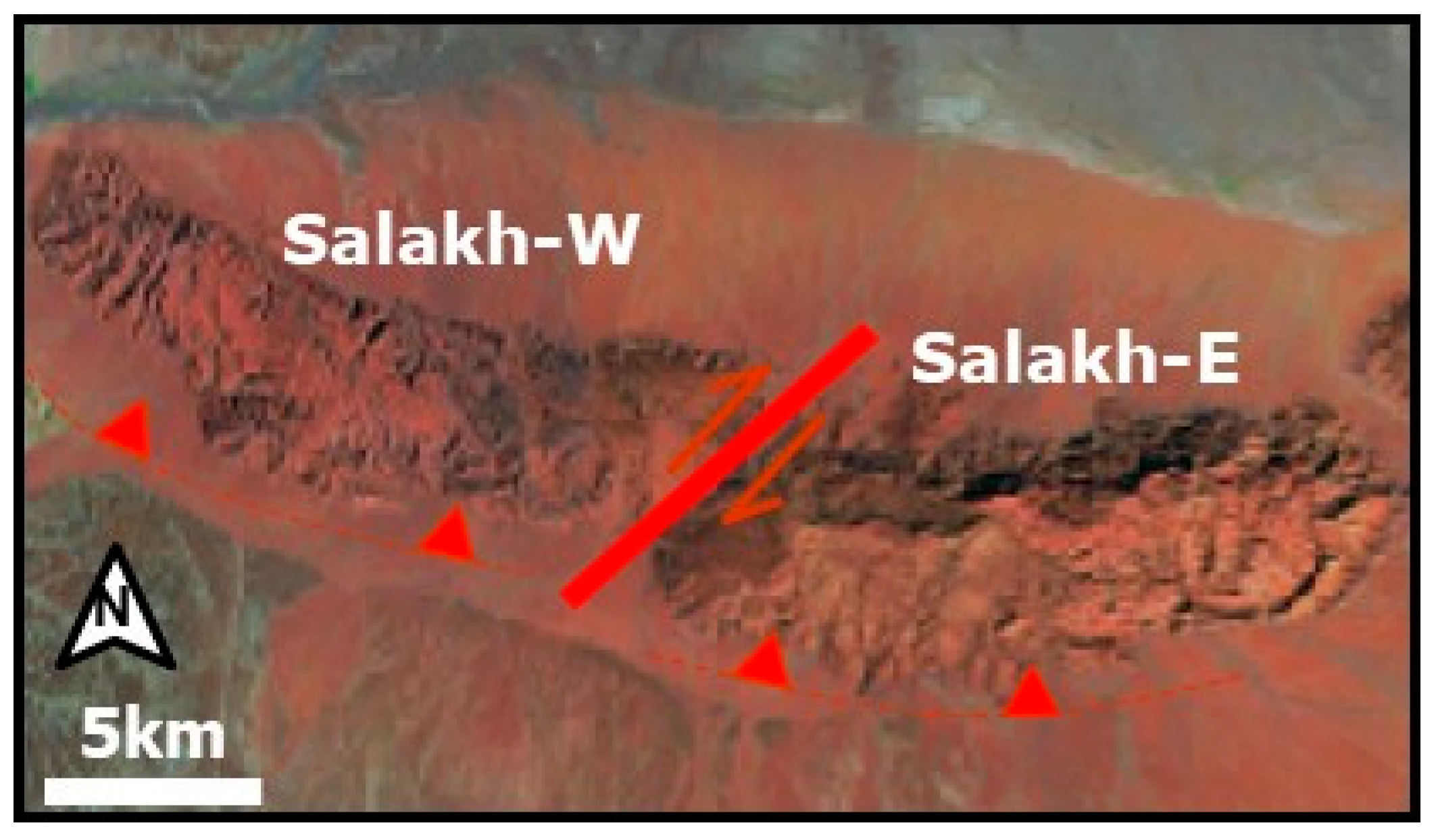
Several faults were formed in the saddle between Salakh E and Salakh W (Figure 6 and Figure 8C). These faults trend NE-SW with a lateral displacement ranging from a few meters up to at least 200 m. The major faults continue through the whole saddle and show right-lateral movement. The flanking structures (e.g., antiforms) that formed close to the fault planes suggest a reverse sense of movement along the faults. Therefore, the faults were most likely created in a transpressional stress regime. They can be described as compartmental faults because they separate two-fold segments with varying shortening magnitudes (average 3.6 km for Salakh E and 3.1 km for Salakh W).

4.5. Salakh E

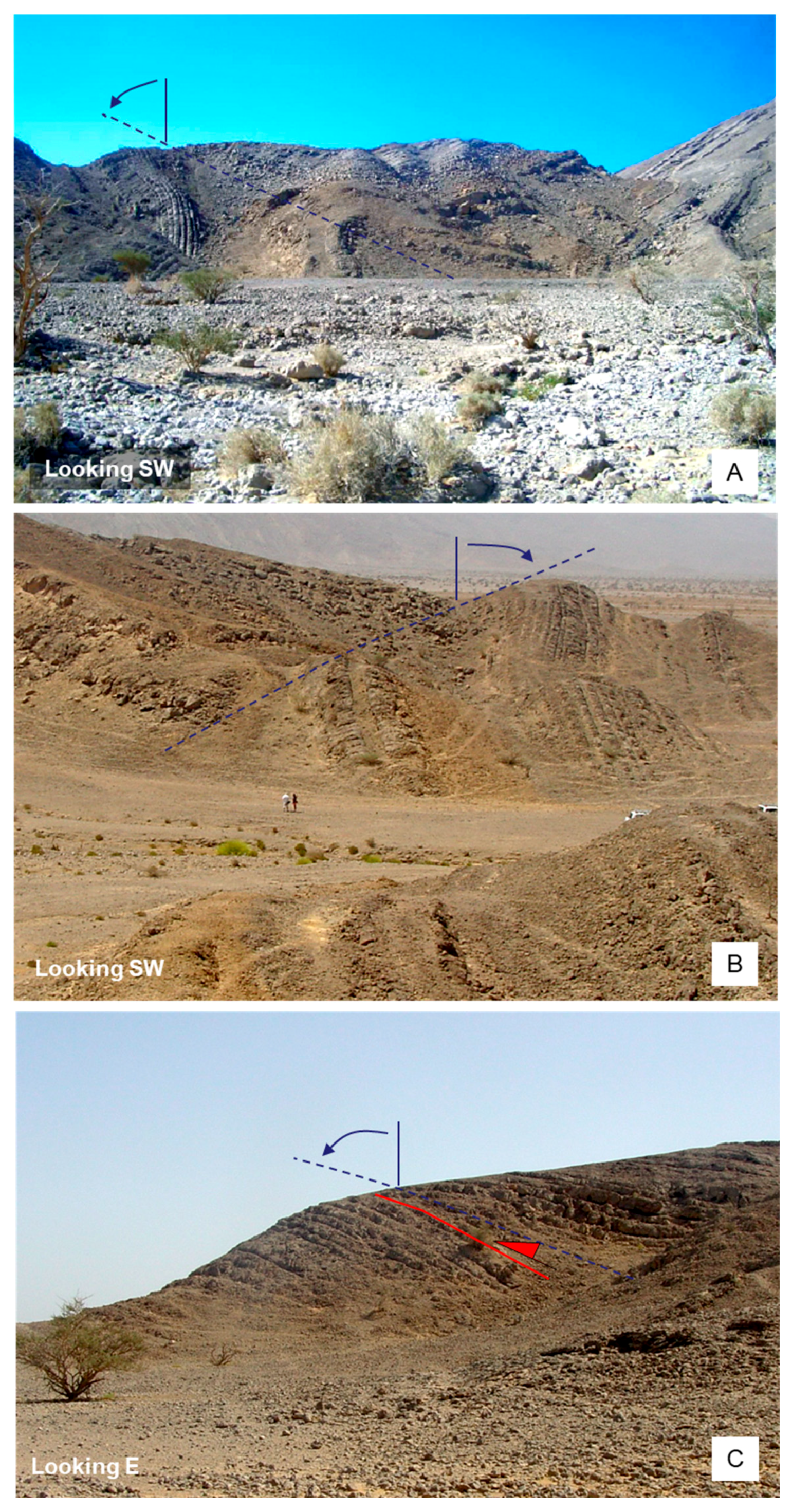
Jebel Salakh E is distinguished from all the other jebels in the Salakh Arch because of its highly uplifted tight box-fold geometry with very steep to overturned limbs and almost flat crest (Figure 6). Moreover, the highly curved hinge zones of Salakh E are well-defined. The Salakh E structure is characterized by major E-W reverse faults that either cut the fold flexures or can be traced on the southern edge of the structure (Figure 6 and Figure 8D). The displacement along these faults measures several hundreds of meters. The flanking flexures of Jebel Salakh E are often bounded by local concentric folds that verge away from the main fold axis and mainly affect the incompetent layers of Natih-D to Natih-B. These folds trend parallel to the Salakh-E axis. They form disharmonic overturned to recumbent structures with amplitudes less than 100m (Figure 9). Collapsed and crumbled rocks occur on both flanks of Salakh E. These are possibly blocks that got suspended within soft sediments or overhanging during the south-verging overthrusting and folding.

4.6. Hinaydil

A major NNW-SSE graben formed in the fold crest subnormal to the Hinaydil fold axis with an offset of more than 70 m, indicating extension parallel to the fold axis (Figure 6). A few NE-SW normal faults have been mapped in the southern limb. These faults were most likely rotated on the structure’s flanks and they occasionally appear with a reverse-sense of movement. Several NE-SW strike-slip faults form in the eastern plunge, most are sinistral faults. A major south-verging reverse fault occurs in the southern flank of Hinaydil with an apparent stratigraphic throw of no less than 80 m (Figure 8E). Along the fault slip plane, horizontal striations are found to post-date the dip-slip grooves. Particularly on its northern flank, Jebel Hinaydil is bounded by a complex set of tight recumbent folds, trending parallel to the Hinaydil fold axis, formed within the Natih C and D strata. These folds verge away from the main Jebel axis on both flanks.

4.7. Madmar

Unlike the other jebels in the Salakh Arch, Jebel Madmar is an open-rounded fold with an overturned forelimb (Figure 6 and Figure 10). Two major sets of normal faulting occur in Jebel Madmar. The NE-SW trending faults are typically formed in the zone of fold-axis orientation change or axis bending, which is only about 2.5 km wide, as shown in Figure 6 and Figure 8F. This strongly suggests that these faults are genetically related to this geometrical change in the fold structure. The faults are often arranged into an en échelon pattern that indicates a dextral movement or clockwise rotation (Figure 8F). NW-SE normal faults are found across Madmar and are often cross-cut by the NE-SW set. Strike-slip faults are predominantly found on both plunges of Jebel Madmar. The sense of movements and palaeostress analyses from these faults are shown in Figure 6. Several reverse faults occur on both limbs of Madmar. Overall, some of them were plausibly inverted from pre-existing Late Cretaceous normal faults. The inversion of the pre-existing faults mainly took place on the limb areas, close to the major thrusts that bound the structure.

5. Results from Subsurface Data

The subsurface data used here include 2-D seismic sections. The subsurface stratigraphy can be divided into five main mechanical units from top to base: the Aruma Group and Cenozoic strata (above Natih); the competent thick-bedded Permian-Cretaceous carbonate platform (top Natih to top Gharif); the incompetent clastic sequence (top Gharif to top Ara Group salt), which is composed of alternating sandstone and shale units, the Ara Salt; and finally the pre-salt formations.
Four seismic sections are presented here to display the main structural styles across the arch, through the fold segments and in the gaps between them.

5.1. Seismic Section 1

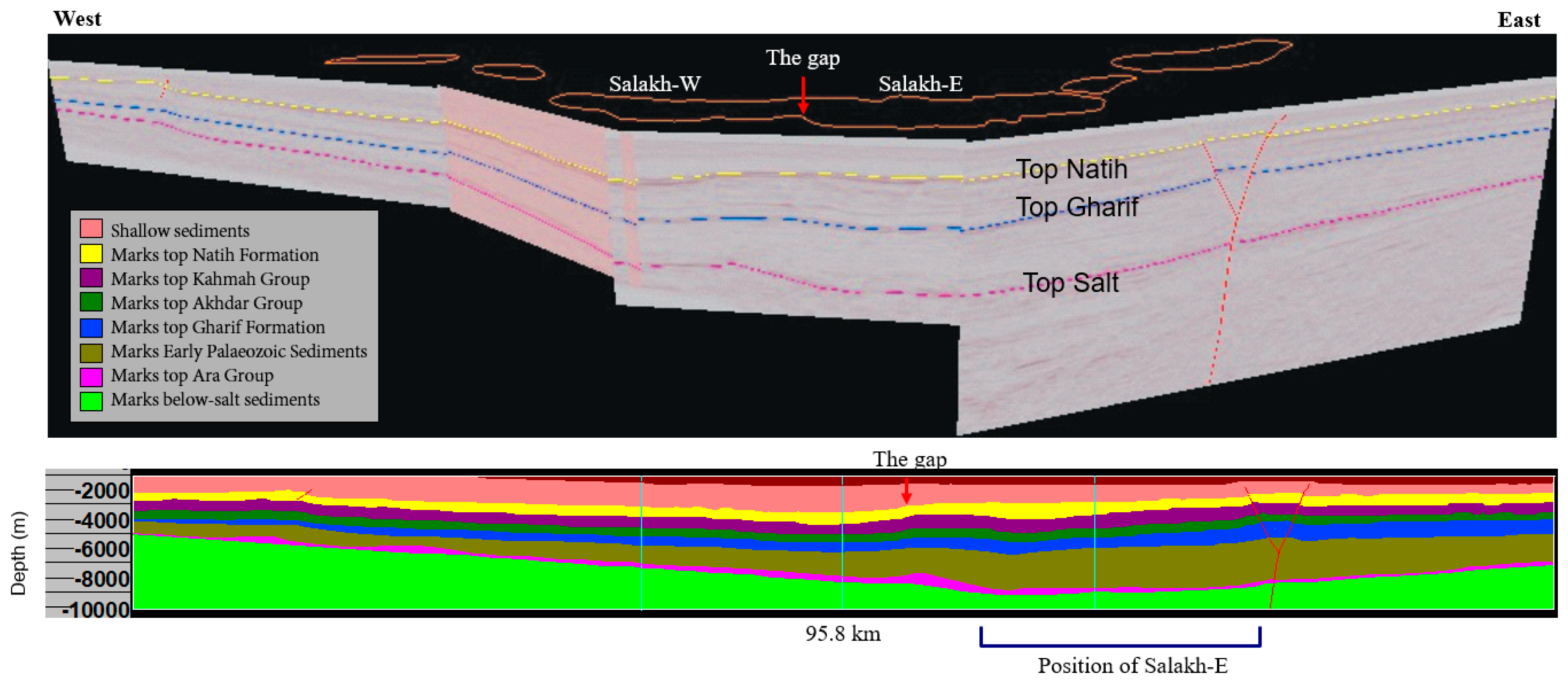
A composite section, referred to here as seismic section 1, was created parallel to the arch using four seismic lines (Figure 11). It illustrates the following important features:
(1) The thickness of the carbonate platform (from top Natih to top Gharif) roughly remains constant throughout the whole arch.
(2) An abrupt change in the thickness of the siliciclastic sequence (from top Gharif to top Salt) coincides with the position of the saddle that separates the Salakh E and the Salakh W structures. The maximum thickness of this sequence along the whole arch corresponds to the position of Jebel Salakh E and it decreases gradually from this position to both the eastern and western sides of the arch.
(3) The thickness of the Ara Salt is possibly minimal at the Madmar structure, which is positioned on the western margin of the Fahud Salt Basin.

5.2. Seismic Section 2 (Nahdah/Salakh W gap)

Seismic section 2 runs perpendicularly to the fold axes of both Nahdah and Salakh W structures (Figure 6) in the gap between them (Figure 12). It illustrates that the Nahdah and Salakh W folds are overlapping, i.e., they do not continue as a single structure in the gap between them. The forethrust of Salakh W has a throw of around 400 m and is interpreted to detach along top Ara Salt. The frontal fault of Nahdah, however, is steep and does not seem to continue below the Gharif reflector. The total shortening estimated from this seismic section is around 2 km (estimated by line-length unfolding of the top Natih reflection). The deformation of the carbonate platform (top Natih to top Gharif) is accommodated by folding and faulting, whereas the deformation in the lower clastic units is possibly partially accommodated by internal folding. Second-order minor folds and faults, below seismic scale, are projected in this zone.

5.3. Seismic Section 3

Seismic section 3 runs through Nahdah oblique ramp (Figure 6 and Figure 13). The continuity to depth of the bounding southern faults in the section is uncertain. It possibly detaches within the Ara Salt or more likely within the thick shale of the siliciclastic units. The depth-to-detachment measurements (based on the equation of depth-to-detachment=deformed area or excess area/amount of shortening, as first defined by Chamberlin [26]) along different seismic sections in the Salakh Arch, strongly indicate a sole detachment along the Ara Salt.
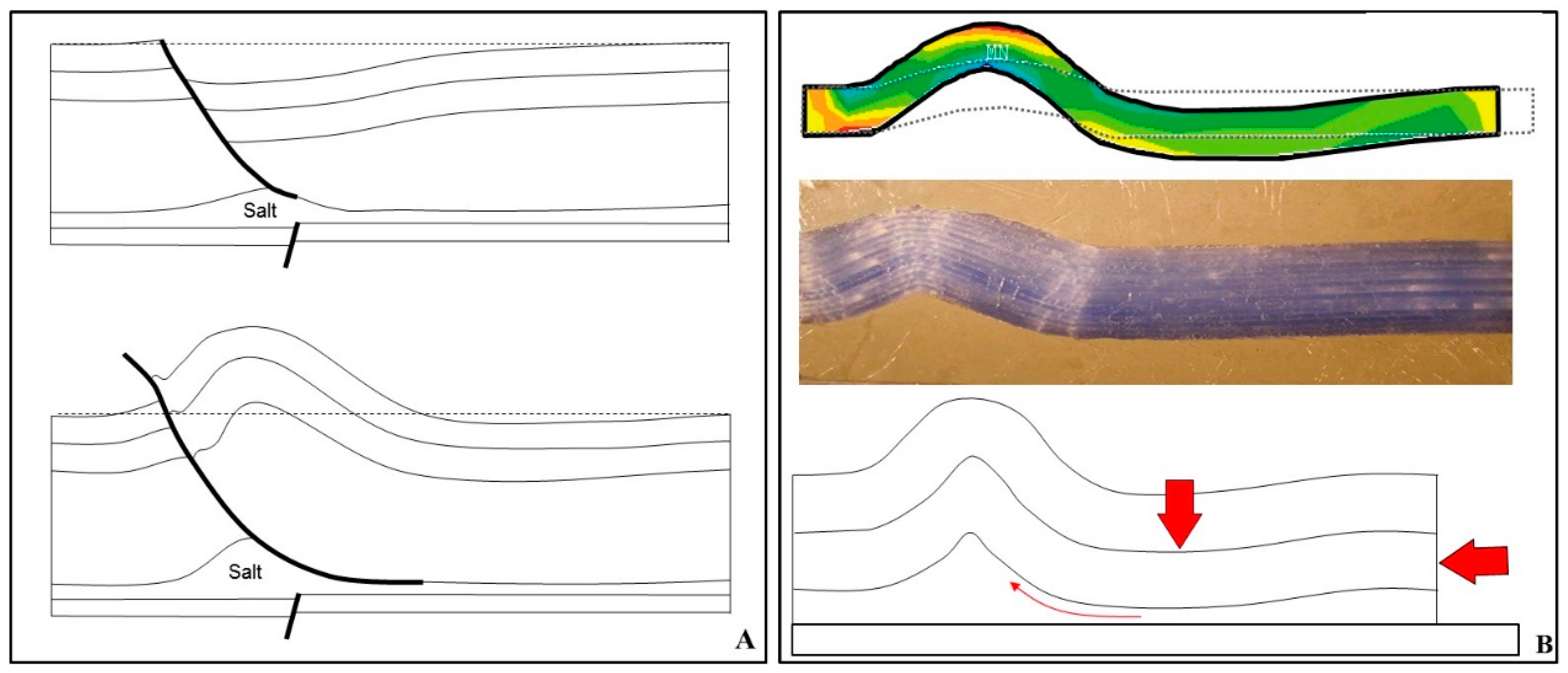
Seismic sections 2 and 3 also show significant folding in the footwall sides of the major frontal reverse faults (on the southern sides of the structures), which is likely related to detachment folding (Figure 14).

5.4. Seismic Section 4 (Salakh Hinaydil and Madmar-Hinaydil gaps)

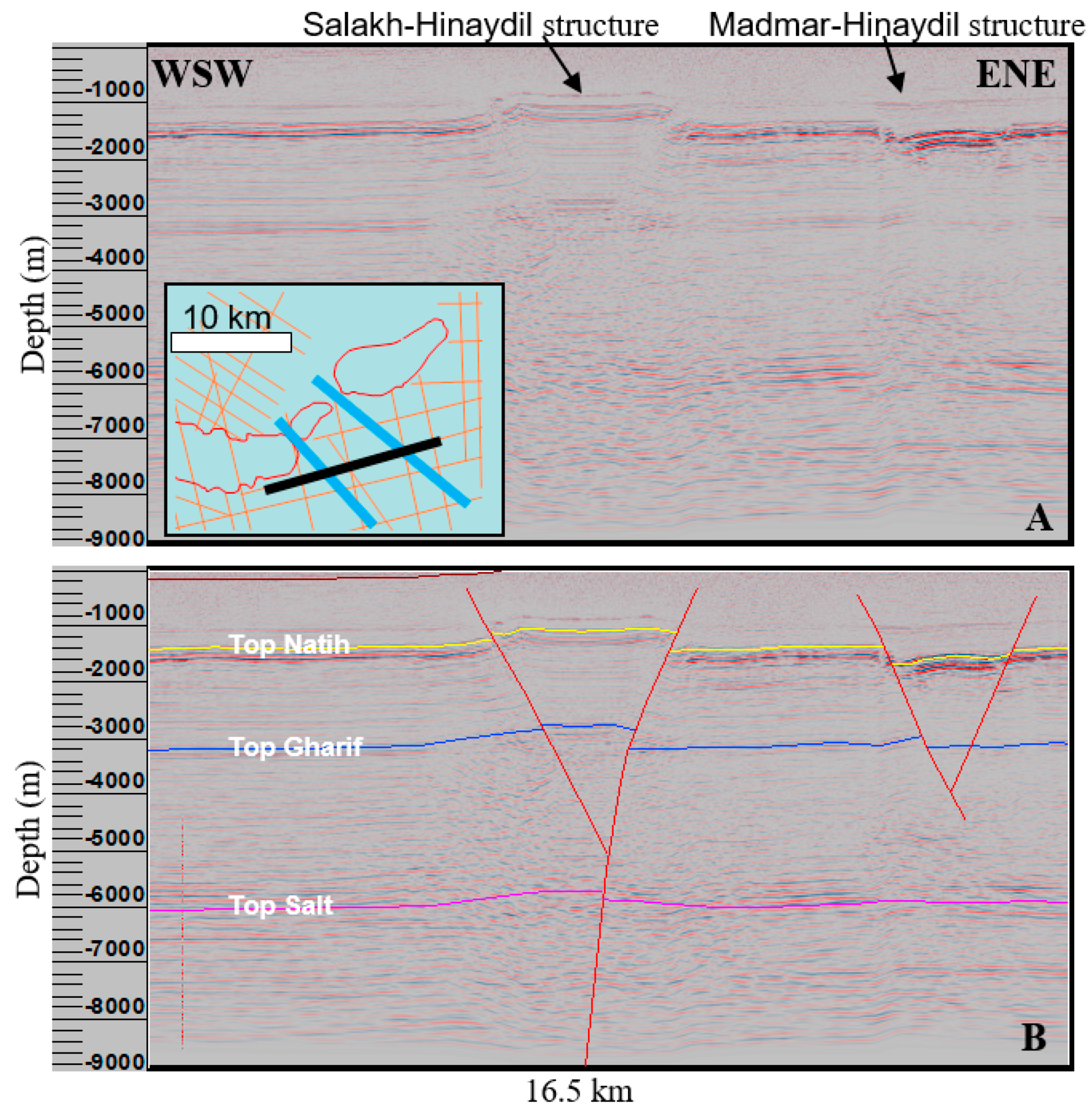
The surface distance between Hinaydil and Salakh E is less than 1.3 km. It distinctively marks the transition from the oblique ramp of Hinaydil with a fold axis of 050° trend to the frontal ramp at Jebel Salakh E, as shown in Figure 6. In addition, the Hinaydil and Madmar structures are separated by a distance of 1.5 km and show lateral offset of fold axes of more than 3 km. A number of seismic lines at the southern side of these gaps (e.g., Figure 15) show two subsurface structural features that run through the gaps. The Salakh Hinaydil structure, also known as “Sulan Salakh”, is most likely a positive flower structure with faults that are rooted below the Ara Salt and can be traced upwards as far as the Aruma strata (Late Cretaceous), before dying out most likely through the Late Cenozoic reflections. On the contrary, the Madmar-Hinaydil structure is a graben with normal faults that plausibly terminate before reaching top Ara Salt. These two subsurface structures are most likely continuous through the Salakh Hinaydil and Madmar-Hinaydil gaps, as evident from their traces on seismic sections (Figure 15).
The thinning and thickening of the Late-Cretaceous sediments over the Salakh-Hinaydil and Madmar-Hinaydil features suggest that these structures were active during the Late Cretaceous. Their orientation and timing strongly suggest a relationship to the Late Cretaceous NW-SE compressive stress, which resulted in two sets of NW-SE transtensional faults. The superposition of Salakh Hinaydil and Madmar-Hinaydil structures at the gaps strongly suggests that they have contributed in the segmentation and separation of the folds as they developed during the Cenozoic. Each of the three folds (Salakh E, Madmar and Hinaydil) has a different geometry, and their fold axes are offset laterally. This indicates that they were possibly separated at the early stages of arch evolution. The Salakh Hinaydil and Madmar-Hinaydil structures have most likely acted as lateral thrust ramps (tear faults) or lateral discontinuities during the Late Cenozoic compression.

6. Interpretation and Discussion

6.1. Interpretation and Discussion Mechanism of Deformation

6.1.1. Arcuate Fold and Thrust Belt Models

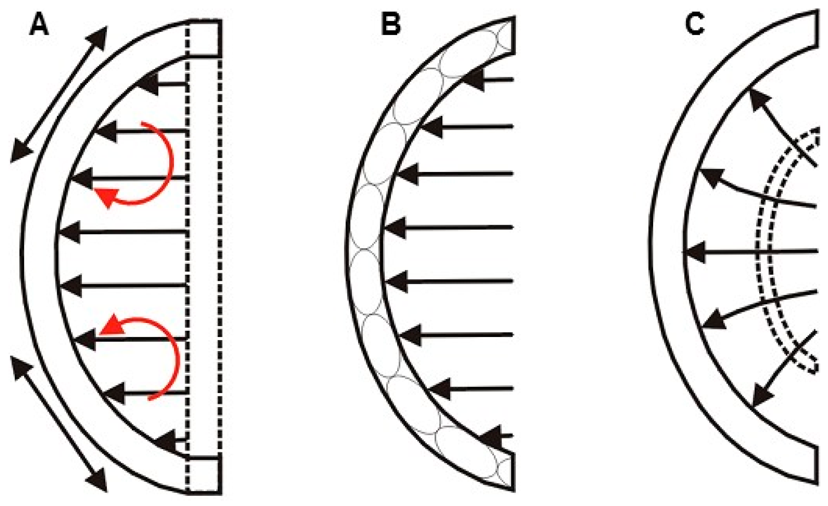
Arcuate FTBs are common around the world (e.g., Jura Mountains, Apennines and Carpathians). They form in various scales and can involve different mechanisms in evolution. Overall, they can be classified into three end members [27] (Figure 16). Oroclines or rotational arcs [28,29,30] occur when the arcuate FTB deforms from a straight zone. The bends develop mainly because of differential displacements along the belt and, therefore, the middle of the salient (convex-to-the-foreland curve) experiences the maximum shortening. Extensional and contractional strains can form in the outer and inner arc, respectively [19,31]. Relative to the direction of transport, the right limbs of the oroclines undergo clockwise rotation, and the left limbs experience anticlockwise rotation. In contrast, primary arcs initiate with an arcuate shape right from the start of deformation. The primary curvature may be induced by a series of boundary conditions [27]. For example, it can be adopted from the shape of a hinterland indenter (e.g., continental promontory) or in relation to a nonlinear continental margin [32]. The oblique ramps in primary arcs deform by both simple and pure shear and, therefore, the overall deformation can be described as transpressional. The third type of arcuate FTB is characterized by primary differential fan-shaped stress trajectories. This type can either initiate from a straight zone then adopt an arcuate shape with incremental strains [33], or it can develop as a primary arc.

6.1.2. Map View Restoration of the Salakh Arch

As previously reviewed, three main theoretical models of the arcuate FTBs have been proposed. These include the orocline bending (secondary arc), primary arc and the divergent transport models. The three models produce discriminated deformation patterns within the resulting arc. The magnitude of displacement values along various parts of the Salakh Arch has been deduced by comparing the length of the deformed and the undeformed states of the structures along top Natih using all the available seismic sections (e.g., seismic section 2 and section 3). These values have been subsequently utilized to predict the position of the undeformed state of the northern flank of the Salakh Arch (Figure 17).
The 2D restoration map, as shown in Figure 17, implies that the Salakh Arch initiated as a primary arc and progressively advanced to the foreland. The map predicts three areas of considerable clockwise or anticlockwise rotation related to differential shortening between adjacent segments. Assuming that this rotation is entirely accommodated by angular shear strains rather than rigid body rotation, the extensional strain that occurred in area 1 is ~ 9%, in area 2 is 6%, and in area 3 is 7%. Area 4 might have undergone arc-parallel extensional strains due to the high deflection of hangingwall materials as they moved on the oblique ramp. The areas that underwent angular shear strains and, therefore, longitudinal extension correspond well with the mapped extensional surface faults that developed perpendicularly to the orientation of the predicted extension. High deflection of materials in the oblique ramp of Nahdah caused arc-parallel extension and possible arc-parallel shortening (fold overlap) in the gap between Nahdah and Salakh W.

6.1.3. Arc-Parallel Extension in Areas 1, 2 and 3

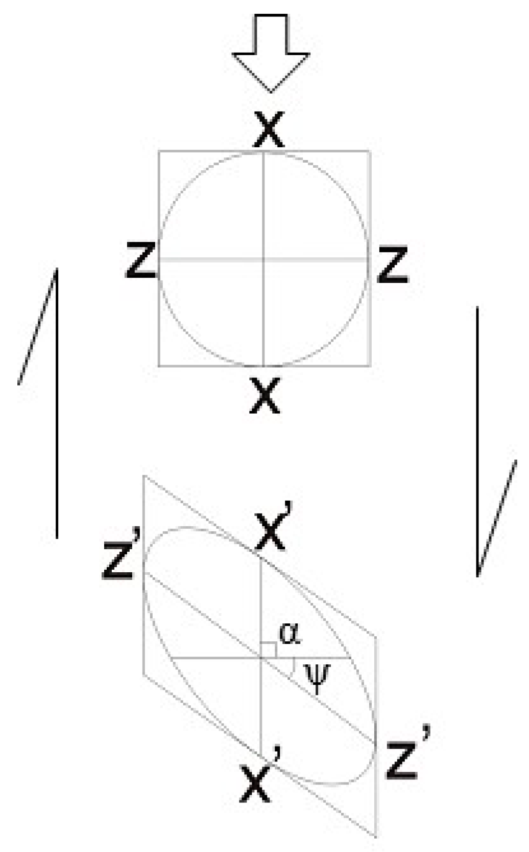
The map scale restoration predicts a considerable change of direction or a vertical-axis rotation of the fold axes in area 1 and area 2 (Nahdah-Salakh W gap and Hinaydil area), which is a consequence of the shortening gradient between the eastern (anticlockwise rotation) or the western oblique (clockwise rotation) ramps and the frontal ramp of Salakh structure. The progressive rotation is assumed to be accommodated by angular shear strain rather than rigid body rotation. The shear strain develops extensional strains parallel to the arch axis. The magnitude of extension can be measured using the following equation, see for example [33,36]:
e = (1 − 2 γ cos α sin α + γ 2 sin2 α) ½ − 1
where α is the angle between the primary line and the displacement direction, and γ is the shear strain, which is given by tan ψ, the angle of shear strain (Figure 18).
When the equation is applied for area 1 and area 2, the resulting longitudinal extension amounts to about 9.5% (clockwise rotation of 16°) and 8% (anticlockwise rotation is 12°), respectively. These extensional strain values can explain the formation of fold-axis perpendicular normal faults in areas 1 and 2.
Jebel Madmar is characterized by NE-SW normal faults that are particularly intensively formed in the zone where the fold axis changes orientation from NE-SW to E-W. These faults form left-stepping en-echelon steps of segments that indicate dextral sense of movement or clockwise rotation. The map-view restoration of the Salakh Arch indicates that the initial trend of the Madmar axis was NE-SW, i.e., oblique to the regional stress direction. This suggests that the Madmar axis has deviated or bent from almost a straight NE-SW direction to its present curved trajectory during the advancement of the arch towards the foreland. The fold-axis rotation, which happened around a vertical axis, was caused by the local differential displacements between the middle part of the jebel and its two sides. This bending produces extensional strain, which is localized in the curved part of the fold axis. The extension is estimated to amount to 9.7% (clockwise rotation of 14°). Similarly to the clockwise angular shear strain, which produced NW-SE maximum extension in the western area of Salakh W, the shear strain in the middle part of Jebel Madmar also caused NW-SE extension (Figure 6). The transport-parallel simple shear causes rotation and extension of the fold axes, which could narrow the radial distance between the folds. This might explain the small width of the Salakh-Hinaydil (1 km) and Madmar-Hinaydil (1.5 km) gaps.

6.1.4. Arc-Parallel Extension in Area 4

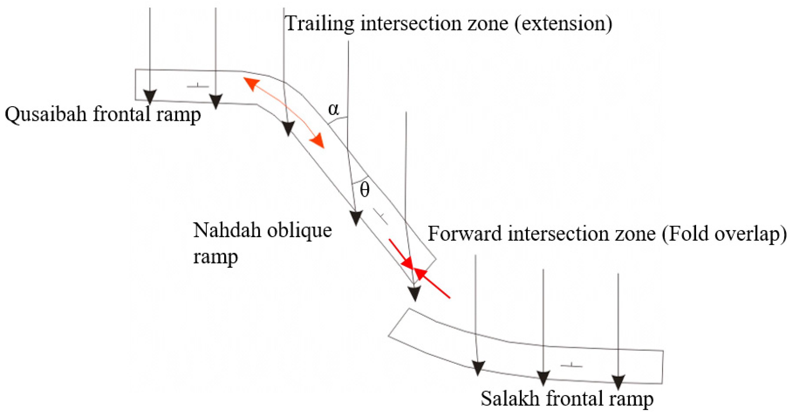
The abundant normal faults that are significantly concentrated in the Nahdah oblique ramp are a possible result of out-of-plane strain, which formed because of materials’ deflection as they move over oblique ramps, as suggested by Apotria et al. [25] and Apotria [37]. The western oblique ramp (Nahdah area) makes an angle of about 50° with the transport direction. According to Apotria et al. [25], when the hanging wall deforms by layer-parallel shear, the direction of movement of materials on the hanging wall side of the fault plane makes a pitch angle (θ) equal to the angle that the oblique ramp is making with the transport direction (α). This means that the displacement vectors along the Nahdah forethrust have a pitch angle of 50° with the strike of the fault, i.e., high out-of-plane strains occurred as the hanging-wall materials moved on the ramp. The fault striations of the reverse faults (e.g., Figure 8A) that bound the Nahdah structure have a similar pitch angle.
As illustrated in Figure 19, the deflection of materials in the trailing intersection zone (concave toward the transport direction) between the oblique ramp and frontal ramp creates local arc-parallel extension [38]. Area 4 has most likely undergone longitudinal extension as it separates between the highly oblique ramp of Nahdah and the frontal ramp of Qusaibah. Some authors have suggested that this extension is regional and covers the entire oblique ramp zone [39]. By contrast, the forward intersection zone will possibly experience strike-parallel shortening or an overlap between the two ramps [25]. This can explain the overlap in the gap between the Nahdah oblique ramp and the Salakh frontal ramp as shown by section 2 in Figure 12.

6.2. Main Controls on the Position and Geometry of the Salakh Arch

Many factors are thought to control the geometry and position of the Salakh Arch. Among these factors are the following:

6.2.1. Thickness Variation of Incompetent Formations along the Salakh Arch

Although the thickness of the carbonate platform does not change significantly along the strike of the arch, the siliciclastic sequence (from top Gharif to top Ara Salt) is extensively thicker in the location of Salakh E than the other parts of the arch, which is the most uplifted and advanced fold segment in the arch (Figure 20). The thickness of the incompetent siliciclastic clastic units decreases to the external parts of the arch. The saddle between Salakh E and Salakh W is also located where an abrupt change, more than 500 m, of the Palaeozoic siliciclastic thickness occurs. These observations suggest a key influence of the siliciclastic thickness on both the structural relief of the folds and the shape of the arch. Several authors have remarked a relationship between the width of the thrust wedge or fold width and the thickness of deformed sediments [29,40,41].
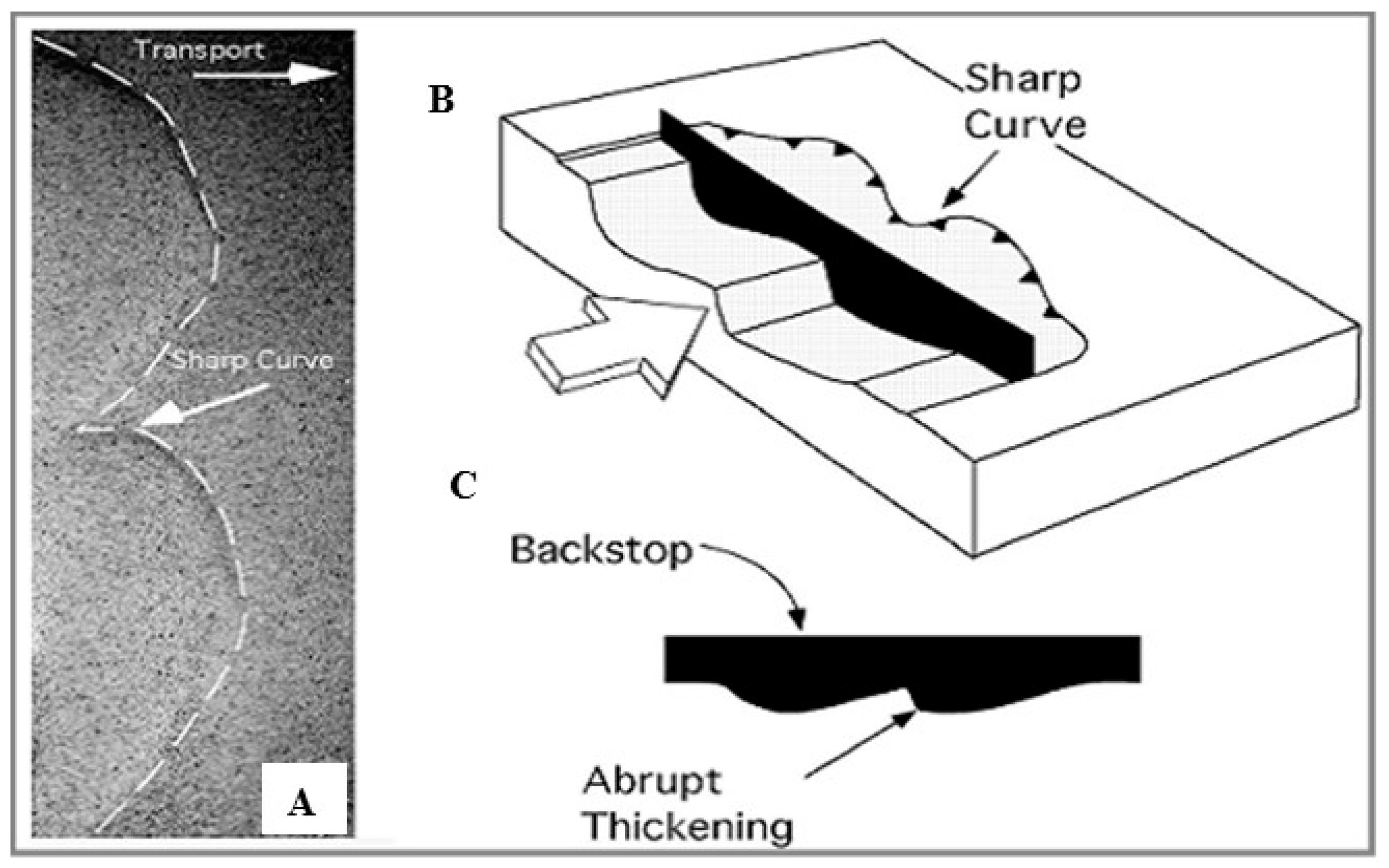
Sandbox experiments also indicate that thrusts with thicker deformed sediments propagate further to the foreland than thrusts with thin sediments [42] (Figure 21). The apex of many arcuate FTBs around the world coincides with the thickest strata along the strike of the deformed area [32].
In general, a wide fold with thick incompetent material filling the fold core and competent units undergoing significant limb rotation by flexural slip deformation can grow faster and become more amplified in response to a given amount of compressional stress, therefore leading to higher values of shortening. This phenomenon can explain the separation and compartmental or tear faults between Salakh E and Salakh W and the wider geometry and more uplifted structure of Salakh E. It could also explain the progressive decrease in Madmar’s fold width towards its eastern side, because the deformed sediments gradually thin in the same direction (Figure 11).

6.2.2. Pre-Existing Faults

Several NW-SE normal and strike-slip faults were formed during Late Cretaceous across Oman [11]. These faults mainly trend around N125° and cluster in major deformation zones in the salt basins (e.g., the Fahud Salt Basin). In the outcrops of the Salakh Arch, these faults are widely spread, and they were often rotated during folding or inverted to reverse faults during the Cenozoic, probably as the reverse faults in the northern limb of Jebel Madmar and the southern limb of Jebel Hinaydil. In the subsurface, these faults include grabens and positive flower structures that developed in the locations of the present Madmar/Hinaydil and Salakh E/Hinaydil gaps, respectively (section 4 in Figure 15). These particular faults have possibly served as lateral ramps during Cenozoic compression. The bounding thrusts of the folds and the styles of folding vary significantly across the gaps. Therefore, Salakh E, Hinaydil and Madmar were most likely uncoupled during the early stages of deformation by the pre-existing faults.
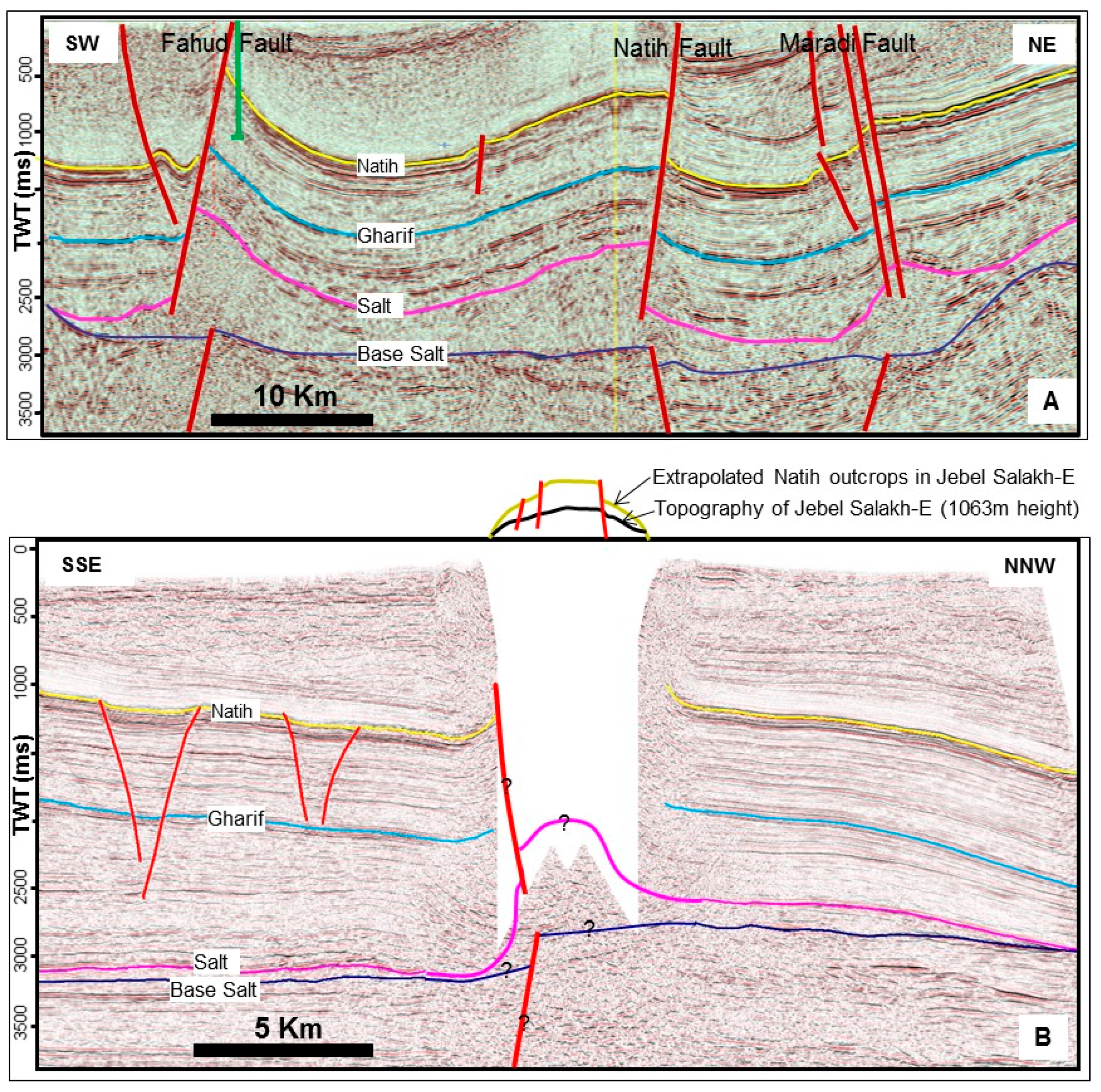
The gravity, magnetic [9] and seismic data indicate that the central and eastern parts of the Salakh Arch (Salakh W, Salakh E, Hinaydil and Madmar) are positioned above a basement fault oriented E-W (Figure 22B), whereas the western part of the arch (Qusaibah and Nahdah) formed above a relatively shallow basement. This is also supported by Al Lazki et al. [21], who indicated that along their geophysical transect, which extends from Jebel Akhdar, through Jebel Qusaibah and into the foreland basin, Jebel Qusaibah is located above a shallow basement of around 8 km depth.

6.2.3. Allochthonous Units

The external parts of the arch (i.e., Qusaibah and eastern Madmar structures) developed just south of the Hawasina nappes (Figure 1 and Figure 2), whereas the apex of the arch (Jebel Salakh) corresponds to the most foreland-advanced sheets of the Allochthonous Hawasina nappes (as mapped from surface and subsurface). The architecture of the Salakh Arch imitates the arcuate shape of Hawasina nappes foreland head, with greater curvature in the Salakh Arch. A number of Cenozoic folds, many with a box-fold geometry, also formed just south of the Hawasina nappes (e.g., Jebel Fajj and Jebel Fida). However, these folds most likely detach within the post-Natih units (e.g., Fiqa shales). It is not proposed here that the Hawasina nappes worked as an indenter for the Cenozoic thrust sheets, contrary to the interpretation provided by Carbon [16]. Rather, the Cenozoic shortening was transmitted to the areas where thinner overlying sediments occur, south of the most advanced part of the Hawasina nappes.

6.2.4. Structural Evolution of the Fahud Salt Basin

The structural setting of the Salakh Arch, as shown by the seismic data, demonstrates some similarities with the other major structural features in the Fahud Salt Basin, particularly the Fahud, Natih and Maradi faults (Figure 1 and Figure 22), with fold structures developing above salt pillows that formed above roughly E-W extensional basement faults. Unlike the fold segments in the Salakh Arch, these major structures have very good coverage of 3D seismic data, hence, providing a very good understanding of the tectonic history in the Fahud Salt Basin. Al Kindi & Richard [3] summarized the tectonic evolution of these structures in the following order. Firstly, transtensional basement faults developed prior to the deposition of the Ediacaran to Early Cambrian Ara Salt Group. The basement faults controlled deposition of the salt and localized later halokinesis. The major faults and folds in the area (e.g., Natih Field in Figure 1) are rooted by these basement faults. Halokinesis was probably a mechanism during deposition of the Palaeozoic siliciclastic sediments. During the Late-Cretaceous NW-SE compression, deformation was mainly localized above pre-existing salt pillows, which are in turn, most likely positioned above basement faults. Major NW-SE transtensional faults, such as the Fahud, Natih and Maradi faults (Figure 1), formed above these salt pillows. During the Late-Cenozoic NE-SW compression, these faults were reactivated as transpressional faults, with various degrees of reverse movement depending on their orientation with respect to the regional stress (Figure 17).
The Salakh E structure most likely developed above a major basement fault as evident from the variation of the Haima Supergroup (from Gharif to Salt reflections) thickness across the northern and southern sides of the Salakh E (Figure 22B). Unlike the Fahud, Natih and Maradi structures (Figure 22A), the Salakh E core structural style cannot be revealed from seismic data. This is also the case for almost all the seismic sections in the Salakh Arch, where the seismic quality deteriorates in the core of the folds.

7. Timing of Deformation

A number of reasons strongly suggest that the Salakh Arch formed during the Late Miocene/Early Pliocene and possibly Early Pleistocene. Among these reasons are:
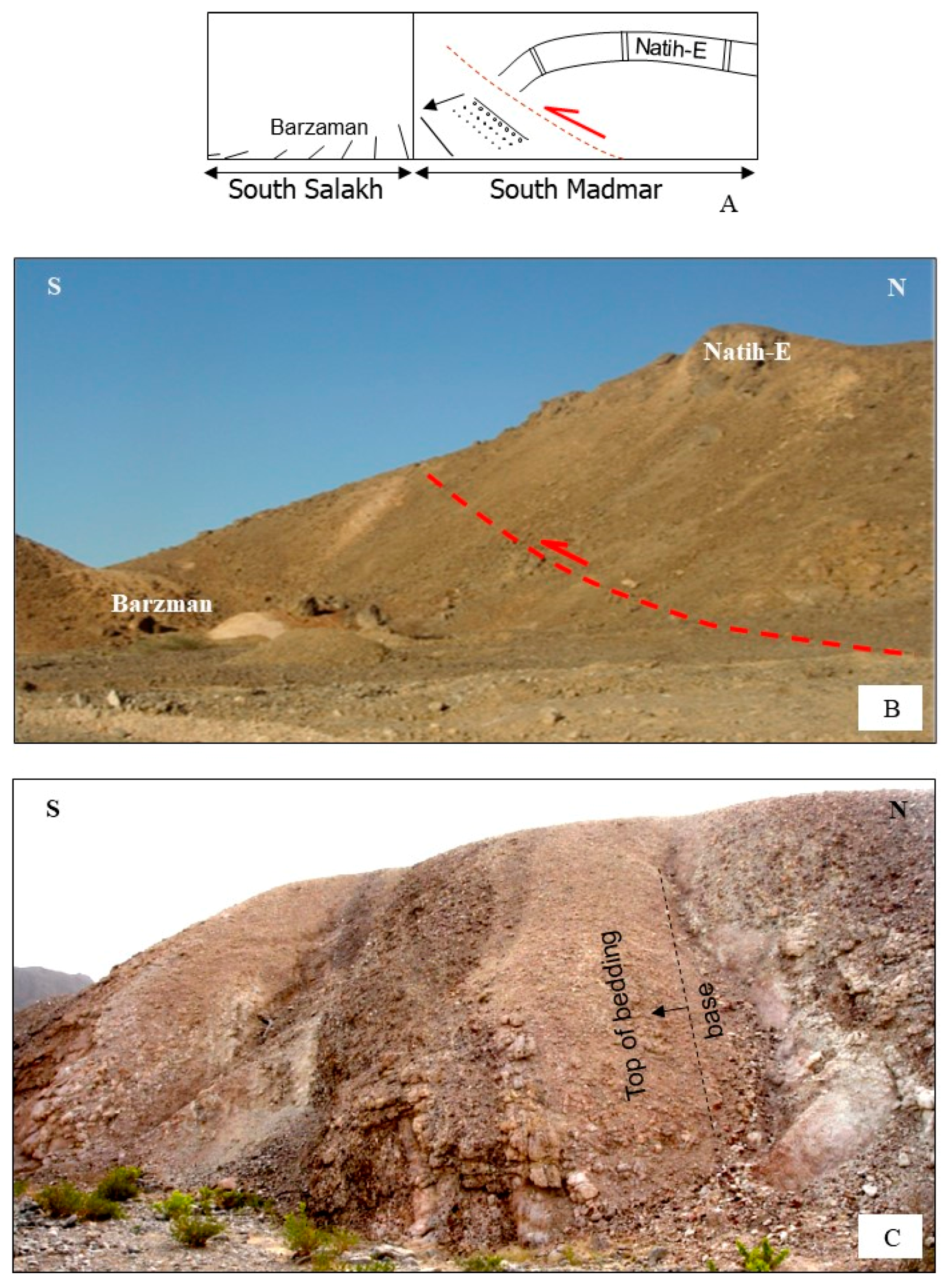
  • On the southern limit of Jebel Madmar, Natih Formation was found to overthrust the lower part of Barzaman Formation. The field data south of Jebel Salakh also indicate that the Barzaman Formation is highly deformed and tilted (Figure 23). A similar observation is seen in the Natih and Fahud hydrocarbon fields where folding affected the Barzaman Formation.
  • The existence of Simsima clasts (the upper part of Aruma Formation that was deposited during the end of Late Cretaceous) in Sufrat Alkhays area (see Figure 1 and Figure 2), which derived from the Simsima shelf edge some distance to the South, and the absence of Natih-derived clasts from the Salakh area [43] indicate that the area had not developed into the present positive geomorphological feature during the Late Cretaceous and was covered by Aruma deposits at that time.
  • The folds and reverse faults were found to displace both the Aruma and Cenozoic strata as shown by several seismic lines (e.g., sections 2 and 4, as shown in Figure 12 and Figure 13).
The oldest alluvial fans of the Barzaman Formation play an essential role in solving the controversy of Cenozoic deformation as it hosts the first clasts derived from the Oman Mountains in this area [5] and, therefore, they mark the history of their uplift and erosion. Disappointingly, however, dating of the Barzaman Formation, particularly its upper part, is only relative. According to Béchennec et al. [44], the basal deposits of Barzaman Formation are assigned to the middle Miocene, based on their interfingering with the marine facies of the Dam Formation. It is assumed that the deposition of these units continued only to the Pliocene because they differ from the Quaternary alluvial fans that contain coarse and varied clasts and were deposited in stepped terraces due to the change of base-level caused by Quaternary glaciations. The lower part of the Barzaman Formation contains clasts that were mainly derived from the Hawasina nappes. It is only in the upper part of Barzaman where small pebbles from the Hajar Supergroup are seen [44]. This strongly suggests that the Salakh Arch did not feed Barzaman with eroded rocks until its late stage of deposition, and, therefore, the Salakh Arch evolution initiated during the end of the Cenozoic and ceased during the Early Quaternary.

8. Conclusions

The Salakh Arch fold-and-thrust belt formed during the Late Miocene/Early Pliocene and possibly continued to the Early Pleistocene. It initiated as a primary arc as verified by the integration of shortening values from seismic sections that are utilized to restore the arc in map view. The restoration predicts areas of clockwise and anticlockwise rotations that were mainly produced by displacement gradients. This rotation is probably accommodated by transport parallel simple shear, which subsequently resulted in longitudinal extension parallel to the arc axis. The quantified amount of extension (by comparing the deformed and undeformed lines of the arc) is 9.5% in the western side of Salakh W, 8% in the position of Hinaydil structure, and 9.7% in the middle part of Jebel Madmar. This strain extends the fold axes and can narrow the gaps between the folds (e.g., Salakh and Hinaydil gap). The extension is trending NE-SW in Jebel Hinaydil and NW-SE in the western part of Salakh W and Madmar area. The oblique ramp areas can also be zones of local arc-parallel extension and shortening as a result of hangingwall material deflections during the movement on oblique ramps. Arc-parallel extension might have occurred in the gap between Jebel Nahdah and Jebel Qusaibah, as represented by major and intensive arc-perpendicular extensional faults. In contrast, arc-parallel shortening may have formed in the gap between Jebel Nahdah and Jebel Salakh. This could also explain the overlap between the Salakh and Nahdah structures along the saddle between them.
The fold segments in the Salakh Arch most likely detach within the underlying Ara Salt. A faulted detachment fold model may explain the diverse geometrical features that developed in the Salakh Arch. It is found to be the most consistent model with a wide variety of subsurface and surface observations in the Salakh Arch. It is also aligned with the depth-to-detachment measurements and the restoration results of the seismic sections. Several factors may have controlled the position and the geometry of the arch and its fold segments. The folds that developed in relatively thick deformed sediments are wide and have been more uplifted. Areas of relatively thicker salt along the arc (e.g., Salakh E) have undergone more folding-accommodated shortening and, therefore, resulted in box-fold geometries, whereas areas with relatively thin salt underwent significant faulting-accommodated shortening (e.g., Madmar) that produced open anticlines with large bounding reverse faults. The basement faults have controlled the position and shape of the Salakh Arch. The salt bodies have been localized above basement faults and highs. Moreover, the pre-existing NW-SE Cretaceous faults have significantly contributed in the segmentation of the folds along the Salakh Arch. The bounding reverse faults of these Salakh Arch fold segments may have been reactivated by pre-existing Late-Cretaceous faults.
Overall, this work suggests that the structural evolution of the Salakh Arch is similar to the tectonic history of the major structures in the Fahud Salt Basin (e.g., Natih and Fahud Fields) basement features. The Salakh Arch has developed as an FTB almost perpendicularly to the regional compression direction.

Funding

The project was partly funded by Petroleum Development Oman, the leading exploration and production company in the Sultanate of Oman.

Acknowledgments

I would like to thank Rob Butler, Martin Casey, Mohammed al Wardi, Jean-Paul Breton, Carine Grélaud and Pascal Richard for all the useful discussions while conducting this work.

Conflicts of Interest

The author declares no conflict of interest. The funders had no role in the design of the study; in the collection, analyses, or interpretation of data; in the writing of the manuscript, or in the decision to publish the results.

References

  1. Gunzenhauser, B. A Review of the Salakh Arch Structures; Confidential Report PDO Exploration Report NO. 85/1; Petroleum Development Oman: Muscat, Oman, 1985. [Google Scholar]
  2. Willis, I.A.G. Qusaybah-1 and an appraisal of the Salakh Arch; Confidential report PDO Exploration Report No.66; Petroleum Development Oman: Muscat, Oman, 1970. [Google Scholar]
  3. Al-Kindi, M.H.; Richard, P.D. The main structural styles of the hydrocarbon reservoirs in Oman. Geol. Soc. Lond. Spec. Publ. 2014, 392, 409–445. [Google Scholar] [CrossRef]
  4. Dercourt, J.; Zonenshain, L.P.; Ricou, L.E.; Kazmin, V.G.; Le Pichon, X.; Knipper, A.L.; Grandjacquet, C.; Sbortshikov, I.M.; Geyssant, J.; Lepvrier, C.; et al. Geological evolution of the Tethys belt from the Atlantic to the Pamirs since the Lias. Tectonophysics 1986, 123, 241–315. [Google Scholar] [CrossRef]
  5. Glennie, K.W. The Geology of the Oman Mountains: An Outline of Their Origin; Scientific Press: Beaconsfield, UK, 1995; Volume 314. [Google Scholar]
  6. Hanna, S.S.; Nolan, S.C. The Maradi fault zone: Evidence of Late Neogene tectonics in the Oman mountains. J. Geol. Soc. 1989, 146, 867–871. [Google Scholar] [CrossRef]
  7. Glennie, K.W.; Boeuf, M.; Hughes-Clarke, M.S.; Pilaar, W.E.H.; Reinhardt, B. Geology of the Oman Mountains; Verh. Koninklijk Nederlands Geologisch Mijnbouwkundig Genootschap, 1974; Available online: https://pascal-francis.inist.fr/vibad/index.php?action=getRecordDetail&idt=PASCALGEODEBRGM7520053086 (accessed on 26 February 2020).
  8. Skelton, P.W.; Nolan, S.C.; Scott, R.W. The Maastrichtian transgression onto the northwestern flank of the Proto-Oman Mountains: Sequences of rudist-bearing beach to open shelf facies. Geol. Soc. Lond. Spec. Publ. 1990, 49, 521–547. [Google Scholar] [CrossRef]
  9. Romine, K.; Stuart-Smith, J.P.; Aitken, R.; Archer, S.; Fryberger, S.; Petrovich, T.; Loutit, J.; Teasdale, C.; Foss, M. North Oman Haima-Huqf Tectonostratigraphy Study; SRK Confidential Report PDO; Petroleum Development Oman: Muscat, Oman, 2004. [Google Scholar]
  10. Warburton, J.; Burnhill, T.J.; Graham, R.H.; Isaac, K.P. The evolution of the Oman Mountains foreland basin. Geol. Soc. Lond. Spec. Publ. 1990, 49, 419–427. [Google Scholar] [CrossRef]
  11. Filbrandt, J.B.; Al-Dhahab, S.; Al-Habsy, A.; Harris, K.; Keating, J.; Al-Mahruqi, S.; Ozkaya, S.I.; Richard, P.D.; Robertson, T. Kinematic interpretation and structural evolution of North Oman, Block 6, since the Late Cretaceous and implications for timing of hydrocarbon migration into Cretaceous reservoirs. GeoArabia 2006, 11, 97–140. [Google Scholar]
  12. Loosveld, R.J.; Bell, A.; Terken, J.J. The tectonic evolution of interior Oman. GeoArabia 1996, 1, 28–51. [Google Scholar]
  13. Ferrill, D.A.; Groshong, R.H., Jr. Kinematic model for the curvature of the northern Subalpine Chain, France. J. Struct. Geol. 1993, 15, 523–541. [Google Scholar] [CrossRef]
  14. Searle, M.P.; James, N.P.; Calon, T.J.; Smewing, J.D. Sedimentological and structural evolution of the Arabian continental margin in the Musandam Mountains and Dibba zone, United Arab Emirates. Geol. Soc. Am. Bull. 1983, 94, 1381–1400. [Google Scholar] [CrossRef]
  15. Fournier, M.; Lepvrier, C.; Razin, P.; Jolivet, L. Post-obduction extension in the Oman Mountains and subsequent compression. GeoArabia 2006, 4, 17–40. [Google Scholar]
  16. Carbon, D. Tectonique Post-Obduction Des Montagnes d’Oman Dans Le Cadre Del La Convergence Arabie-Iran. Ph.D. Thesis, Universite Montpellier II (Sciences et techniques du Languedoc), Montpellier, French, 1996. [Google Scholar]
  17. Boote, D.R.D.; Mou, D.; Waite, R.I. Structural evolution of the Suneinah foreland, central Oman Mountains. Geol. Soc. Lond. Spec. Publ. 1990, 49, 397–418. [Google Scholar] [CrossRef]
  18. Hanna, S.S. The Alpine deformation of the central Oman Mountains. Geol. Soc. Lond. Spec. Publ. 1990, 49, 341–359. [Google Scholar] [CrossRef]
  19. Mount, V.S.; Crawford, R.I.; Bergman, S.C. Regional structural style of the central and southern Oman Mountains: Jebel Akhdar, Saih Hatat, and the northern Ghaba Basin. GeoArabia 1998, 3, 475–490. [Google Scholar]
  20. Mann, A.; Hanna, S.S.; Nolan, S.C. The post-Campanian tectonic evolution of the central Oman Mountains: Tertiary extension of the eastern Arabian margin. Geol. Soc. Lond. Spec. Publ. 1990, 49, 549–563. [Google Scholar] [CrossRef]
  21. Al-Lazki, A.I.; Seber, D.; Sandvol, E.; Barazangi, M. A crustal transect across the Oman Mountains on the eastern margin of Arabia. GeoArabia 2002, 7, 47–78. [Google Scholar]
  22. Angelier, J.; Mechler, P. Sur une méthode graphique de recherche des contraintes principales également utilisable en tectonique et en séismologie: La méthode des dièdres droits. Bulletin de la Société géologique de France 1977, 7, 1309–1318. [Google Scholar] [CrossRef]
  23. Breton, J.P.; Béchennec, F.; Le Métour, J.; Moen-Maurel, L.; Razin, P. Eoalpine (Cretaceous) evolution of the Oman Tethyan continental margin: Insights from a structural field study in Jabal Akhdar (Oman Mountains). GeoArabia 2004, 9, 41–58. [Google Scholar]
  24. Reiter, F.; Acs, P. TectonicsFP (Demo Version). Available online: www.tectonicsfp.com (accessed on 26 June 2019).
  25. Apotria, T.G. Thrust sheet rotation and out-of-plane strains associated with oblique ramps: An example from the Wyoming salient USA. J. Struct. Geol. 1995, 17, 647–662. [Google Scholar] [CrossRef]
  26. Chamberlin, R.T. The Appalachian folds of central Pennsylvania. J. Geol. 1910, 18, 228–251. [Google Scholar] [CrossRef]
  27. Hindle, D.; Burkhard, M. Strain, displacement and rotation associated with the formation of curvature in fold belts; The example of the Jura arc. J. Struct. Geol. 1999, 21, 1089–1101. [Google Scholar] [CrossRef] [Green Version]
  28. Carey, S.W. The orocline concept in geotectonics-Part, I. In Proceedings of the Royal Society of Tasmania; 1955; Volume 89, pp. 255–288. Available online: https://eprints.utas.edu.au/13965/ (accessed on 26 February 2020).
  29. Marshak, S. Kinematics of orocline and arc formation in thin-skinned orogens. Tectonics 1988, 7, 73–86. [Google Scholar] [CrossRef]
  30. Marshak, S.; Wilkerson, M.S.; Hsui, A.T. Generation of curved fold-thrust belts: Insight from simple physical and analytical models. In Thrust Tectonics; Springer: Berlin/Heidelberg, Germany, 1992; pp. 83–92. [Google Scholar]
  31. Kwon, S.; Mitra, G.; Sussman, A.J.; Weil, A.B. Strain distribution, strain history, and kinematic evolution associated with the formation of arcuate salients in fold-thrust belts: The example of the Provo salient, Sevier orogen, Utah. Orog. Curv. Integr. Paleomagn. Struct. Anal. Geol. Soc. Am. Spec. Pap. 2004, 383, 205–223. [Google Scholar]
  32. Macedo, J.; Marshak, S. Controls on the geometry of fold-thrust belt salients. Geol. Soc. Am. Bull. 1999, 111, 1808–1822. [Google Scholar] [CrossRef]
  33. Affolter, T.; Gratier, J.P. Map view retrodeformation of an arcuate fold-and-thrust belt: The Jura case. J. Geophys. Res. Solid Earth 2004, 109 (B3). [Google Scholar] [CrossRef]
  34. Casas, A.M.; Simon, J.L.; Seron, F.J. Stress deflection in a tectonic compressional field: A model for the Northwestern Iberian Chain, Spain. J. Geophys. Res. Solid Earth 1992, 97, 7183–7192. [Google Scholar] [CrossRef]
  35. Sussman, A.J.; Butler, R.F.; Dinarès-Turell, J.; Vergés, J. Vertical-axis rotation of a foreland fold and implications for orogenic curvature: An example from the Southern Pyrenees, Spain. Earth Plan. Sci. Lett. 2004, 218, 435–449. [Google Scholar] [CrossRef]
  36. Ramsay, J.G.; Huber, M.I. The Techniques of Modern Structural Geology; Folds and fractures Academic press: Amsterdam, The Netherlands, 1987; Volume 2. [Google Scholar]
  37. Apotria, T.G.; Snedden, W.T.; Spang, J.H.; Wiltschko, D.V. Kinematic models of deformation at an oblique ramp. In Thrust Tectonics; Springer: Berlin/Heidelberg, Germany, 1992; pp. 141–154. [Google Scholar]
  38. Coward, M.P.; Potts, G.J. Complex strain patterns developed at the frontal and lateral tips to shear zones and thrust zones. J. Struct. Geol. 1983, 5, 383–399. [Google Scholar] [CrossRef]
  39. Butler, R.W. The terminology of structures in thrust belts. J. Struct. Geol. 1982, 4, 239–245. [Google Scholar] [CrossRef]
  40. Boyer, S.E. Sedimentary basin taper as a factor controlling the geometry and advance of thrust belts. Am. J. Sci. 1995, 295, 1220–1254. [Google Scholar] [CrossRef]
  41. Lacombe, O.; Mouthereau, F.; Angelier, J.; Chu, H.T.; Lee, J.C. Frontal belt curvature and oblique ramp development at an obliquely collided irregular margin: Geometry and kinematics of the NW Taiwan fold-thrust belt. Tectonics 2003, 22, 1025–1034. [Google Scholar] [CrossRef] [Green Version]
  42. Paulsen, T.; Marshak, S. Origin of the Uinta recess, Sevier fold–thrust belt, Utah: Influence of basin architecture on fold–thrust belt geometry. Tectonophysics 1999, 312, 203–216. [Google Scholar] [CrossRef]
  43. Hanna, S.S.; Smewing, J. The stratigraphy and structure of the Madmar-Salakh Qusaybah Range and Natih-Fahud Area in the Oman Mountains. Sci. Technol. 1996, 1, 1–19. [Google Scholar]
  44. Béchennec, F.; Wyns, R.; Roger, J.; Le Metour, J.; Chevrel, S. Geological Map of Nazwa NF40-07. Scale 1/250,000, Explanatory Notes; Directorate General of Minerals, Ministry of Petroleum and Minerals: Muscate, Oman, 1992.
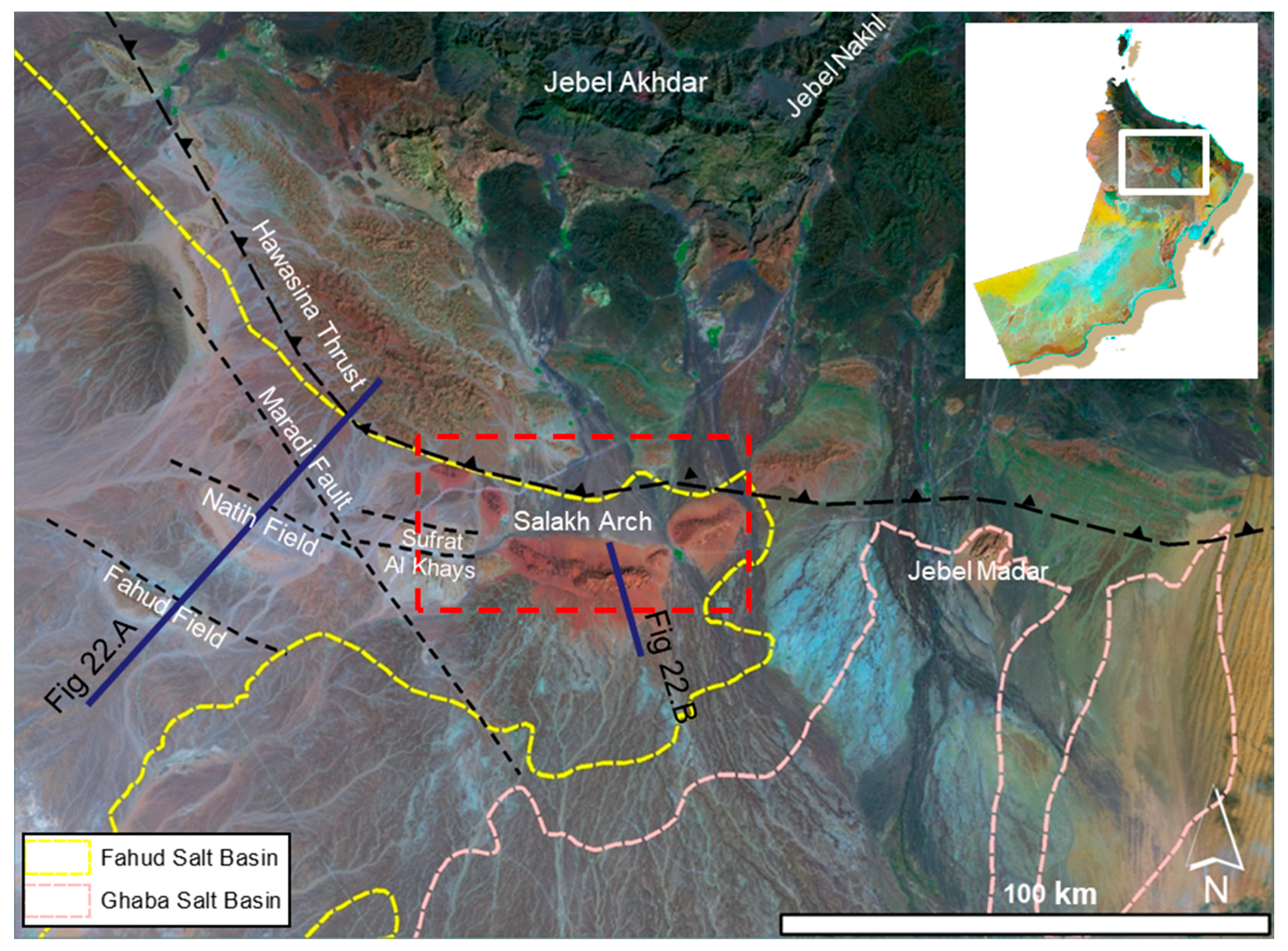
Figure 1. A LANDSAT image showing the position of the Salakh Arch on the eastern side of the Fahud Salt Basin (dashed yellow line). The arch formed S of the most advanced part of the Hawasina nappes, and NE of the Maradi Fault System. The red dashed line shows the location of the geological map in Figure 2. The oil fields of Natih and Fahud are both bounded by major faults.
Geosciences 10 00095 g001
Figure 2. A Geological map of the Salakh Arch. The dashed red line indicates the inferred location of the Hawasina nappes front.
Geosciences 10 00095 g002
Figure 3. Palaeographic reconstruction during: (A) Late Cretaceous, (B) Neogene and (C) today, modified mainly from [9].
Geosciences 10 00095 g003
Figure 4. Map-view illustrations of the stress regimes during: (A) Late Cretaceous, (B) Late Cenozoic, and the types of faults that developed and were reactivated in both times [3].
Geosciences 10 00095 g004
Figure 5. On the left is a simplified stratigraphical column of the five main mechanical packages (Aruma and Tertiary deposits, package/1, package/2, Ara Salt and basement) of Oman. The “basement” is considered to be all the units below Salt. The column also marks the position of the interpreted horizons in the seismic sections. On the right, a stratigraphic column based on the outcrops of the Barzaman conglomerate (with the interfingering formation of Dam limestone.), Muti, Natih, Nahr Umr, Shuaiba, Kharaib and Lekhwair Formations.
Geosciences 10 00095 g005
Figure 6. A summary of the structures in different segments of the Salakh Arch. The figure also highlights the areas (red arrows) that underwent arc-parallel or are-oblique extensions. The black arrows show the orientation of the maximum compression in various parts of the arch as suggested by the fold-axis orientations and/or the palaeostress analyses of σ-1 (showing as red dots in the palaeostress plots) from the kinematics of the strike-slip faults. The figure also shows the location of the surface and subsurface sections.
Geosciences 10 00095 g006
Figure 7. Surface cross sections through Jebel Qusaibah. The locations of the cross sections are shown in Figure 6.
Geosciences 10 00095 g007
Figure 8. (A) a thrust plane in the northern flank of Jebel Nahdah, close to the northern-bounding thrust, plausibly tilted by the folding process. Note that the fault currently looks like having a normal sense of movement. (B) A graben structure in the western part of Salakh W formed by fold-axis parallel extension, (C) a strike-slip fault zone separating the structures of the Salakh E from Salakh W, (D) a thrust in the northern flank of Jebel Salakh E, (E) a major thrust in the southern flank of Jebel Hinaydi, (F) a map view of the NE-SW fault zone in Jebel Madmar. The faults are transtentional and the stepping of their trajectories indicate dextral lateral movement.
Geosciences 10 00095 g008
Figure 9. Examples of the flanking folds in (A) Jebel Salakh E and in (B) and (C) Jebel Hinaydil that verge away from the main fold axes. The fold axes of the flanking folds are shown as dashed blue lines.
Geosciences 10 00095 g009
Figure 10. Surface cross sections through Jebel Madmar. The locations of the cross sections are shown in Figure 6.
Geosciences 10 00095 g010
Figure 11. Four seismic lines, forming composite seismic section 1, in depth were used to create an arc-parallel seismic section that shows the thickness of the formations on the southern side of the arch. The section shows that the saddle between the Salakh E and Salakh W structures coincides with an abrupt change of the Haima Supergroup thickness (from Gharif to Ara Salt reflectors). Also, the Salakh E structure developed at the location of the thickest zone of the Haima Supergroup in the entire arch.
Geosciences 10 00095 g011
Figure 12. (A) Uninterpreted and (B) interpreted sections of seismic line 2. The location of the section is shown in Figure 6.
Geosciences 10 00095 g012
Figure 13. (A) Uninterpreted and (B) interpreted section of seismic line 3. The location of the section is shown in Figure 6. Note that the northern side of top Natih is lower than the southern side.
Geosciences 10 00095 g013
Figure 14. Two possible scenarios of the development of hanging wall synclines, as seen along the Nahdah and Qusaibah areas. (A) these synclines developed as drag folds along extensional faults that formed during the Late Cretaceous and were inverted during Late Cenozoic. This model might also explain the formation of the flanking folds that verge away from the main fold axes, as seen in the Salakh E and Hinaydil structures. (B) These synclines are a result of buckling caused by the Cenozoic shortening. The numerical modelling in ANSYSED was produced with about 1.5 km shortening. The other side of the layer is fixed in both X and Y directions. The formation of the anticline as a result of buckling is accompanied by a wide syncline in the moving part. The sandbox model in the middle shows an example of wide synclines developing in the hinterland due to fold buckling. The schematic diagram shows the mechanism of salt migration from the area underlying the syncline towards the anticlinal core.
Geosciences 10 00095 g014
Figure 15. (A) interpreted and (B) uninterpreted seismic line along the southern flanks of the Salakh, Hinaydil and Madmar-Hinaydil gaps. The black line in the inset figure shows the location of the seismic section, whereas the blue lines show the orientations of the two structures through the gaps.
Geosciences 10 00095 g015
Figure 16. The classification of arcuate FTBs to (A) an “orocline” or a “secondary arc” that bends from a straight line to arcuate shape; (B) a “primary arc” which initiates as a primary arc; (C) a “divergent-transport arc” is formed by fan-shaped stress trajectories. The dashed area in (A) and (C) is the pre-deformational shape of the arc. Note that the first two types can also form with a divergent primary transport direction. Although the transport direction in the primary arc can be unidirectional, the shortening in the transverse deformation zone (oblique and lateral ramps) leads to considerable local deviation or vertical rotation of the finite strain axes from the regional direction of transport stresses [13,28,29,30,31,32,34,35]. This non-parallelism produces wrench deformation in oblique and lateral ramps.
Geosciences 10 00095 g016
Figure 17. A map-view restoration of the Salakh Arch using the shortening values (in km) measured directly from seismic sections or estimated from surface cross sections. The black lines are normal faults in areas 1, 2, 3, and 4. The pink and dark red lines are transpressional and transtensional flower structures, respectively, as shown in Section 2, Figure 15.
Geosciences 10 00095 g017
Figure 18. Simple illustration of the longitudinal strains (Z’Z’) produced by simple shear strain. The simple shear is associated here with pure shear related to regional shortening.
Geosciences 10 00095 g018
Figure 19. A simple map-view illustration of the divergence of hangingwall materials as they move through the Nahdah’s oblique ramp (α = θ) (insight from Apotria’s model [25,37]. The arrows represent the transport directions. Arc-parallel extension developed between the Qusaibah and Nahdah structures and arc-parallel shortening or overlap formed between the Nahdah and Salakh structures.
Geosciences 10 00095 g019
Figure 20. LANDSAT image of the Salakh E, Salakh W and the Z-shaped saddle between them. The Salakh E structure propagated farther to the foreland than Salakh W. Top Natih Formation has been uplifted to 1060 m above sea level in Salakh E, whereas its maximum uplift in the Salakh W is only around 800 m. Plausibly, this compartmental fault forms early during the arch’s evolution. As the fold segments grew and arch progressed to the foreland, the fault developed as a strike-slip fault, oblique to the regional compression, with some reverse sense of movement.
Geosciences 10 00095 g020
Figure 21. Sandbox model by Paulsen and Marshak [42] assessing the origin of the Uinta recess in the Sevier FTB. The model was set to test the relationship between the thickness of sediments involved in thrusting and the propagation of the FTB to the foreland. (A) Sandbox model, viewed from above. (B) The backstop was pushed to the right into a layer of sand. (C) The top and base of the backstop is variable along the strike, which allows variation in thickness of the sediment involved in thrusting. The experiment shows that whenever the sand wedge is thicker (i.e., more depth to detachment), the thrusts propagate farther to the foreland. A sharp curve occurs at the position of the abrupt change in thickness. Although the experiment is useful to explore the effect of sediment thickness on thrust propagation, it does not explain the reason of this relationship. Also, it does not account for the differential uplift that we see between Salakh E (thicker sediments involved in the deformation) and Salakh W (thinner sediments), which is primarily caused by more incompetent materials filling the core of the anticline.
Geosciences 10 00095 g021
Figure 22. A comparison between the structures that developed in the Fahud Salt Basin. (A) Fahud, Natih and the Maradi Fault System. These three structures are underlain by thick salt bodies that most likely localized above basement faults or steps. (B) The Salakh E structure uses a seismic line that was acquired on both sides of the Jebel, hence, a simple surface cross-section is constructed to compare it with subsurface reflections. The locations of these seismic lines are shown in Figure 1.
Geosciences 10 00095 g022
Figure 23. (A) The collapsed blocks in southern areas of Salakh E and Madmar formed in areas where the Natih Formation is found to overthrust the outcropping unconsolidated conglomerate and marls of the Barzaman and Fiqa formations. (B) Natih-E beds overthrusted above Barzaman Fm in South Madmar. (C) Isolated outcrops of overturned Barzaman Fm in South Salakh. In both locations, the Barzaman and Fiqa beds approximately strike parallel to the main fold axes. These soft rocks get eroded easily and the overlying thrusted carbonate beds consequently collapse.
Geosciences 10 00095 g023