1. Introduction
Due to the hilly morphology of the territory, the construction of two new road segments close to the Ionian coast of the Calabria region, southern Italy, required the execution of several excavations (trenches and tunnels), embankments and bridges to comply with the strict geometric prescriptions of modern standards for high speed roads. A large part of the work was to do with the Plio-Pleistocene over-consolidated clayey deposit, often known as the Blue Clay formation, that is outcropping along the East margin of Central and Southern Italy. This formation, constituted of a succession of grey-blue silty and marly clays with thin silty and sandy layers, exhibits very good mechanical characteristics, in terms of stiffness and strength, at the scale of the samples but, when considered as a whole, it becomes very weak because its mechanical response is governed by the presence of discontinuities along which the strength is typically at residual. As firstly pointed out by Esu (1966) [
1] more than 50 years ago, this observation has great engineering implications because the high strength measured in laboratory tests on intact samples is often not applicable to real field conditions. Terzaghi (1936) [
2] had already recognized the importance of the strength degradation processes in stiff clay formations after excavation. With the growing need for underground infrastructures, such processes are of major concern for geotechnical engineers when dealing with excavations in the so-called structurally complex formations (Luongo et al. 2019 [
3]); in such cases, very often the design strategy has to rely on previous studies and existing knowledge of the mechanical response of these materials.
According to Croce (1977) [
4], “structurally complex formations” are those geological deposits that cannot be confidently studied and modelled with the classical approaches of soil mechanics as a consequence of their complicated lithological and structural features. The complexity can derive from the inherent heterogeneity of the ground and/or the presence of discontinuities. Esu (1977) [
5] proposed a general classification of the structurally complex formations by distinguishing three main groups, named A, B, and C. By moving from group A to C, the degree of complexity increases: group A includes jointed (A1) or sheared (A2) clay shales; group B collects stratified formations in which competent rock layers alternate with clay or clay shales, in ordered sequence (B1), disarranged way (B2) or chaotic structure (B3); C represents formations in which the original setting is lost and blocks or fragment of rocks are dispersed in a clayey matrix. In this general framework, as pointed out by D’Elia et al. (1998) [
6], the Plio-Pleistocene formation constitutes a subgroup of structurally complex formations, to be classified as Stiff Jointed Clay formation (SJC) and to be included in groups A1, A2 or B1 according to Esu.
Based on the works of Esu (1966) [
1] and Skempton and Petley (1967) [
7], discontinuity is the most general term to indicate a surface that interrupts the continuity of the soil mass, regardless of its origin and properties. Bedding planes, fissures, and syneresis cracks are discontinuities due to factors operating during the sedimentation of the formation. Discontinuities induced by the stress-strain history are distinguished on the base of the relative movement experienced at the interface. Specifically these are joints when the relative displacement is close to zero, they are minor shears (i.e., Riedel and thrust shears), if the relative movement is less than 10 mm, they are principal displacement shears (i.e., faults and landslide slip surfaces) for relative displacements greater than 100 mm.
Regarding to the mechanical properties of SJC, the studies of Marsland and Butler (1967) [
8], Skempton and Petley (1967) [
7], Calabresi and Manfredini (1973) [
9], and Cotecchia and Chandler (1997) [
10] can be taken as a comprehensive bibliography. These authors tested samples of structured overconsolidated clays and compared the strength measured along discontinuities with that of intact samples. The intact samples showed brittle behaviour with a clear peak, followed by a sharp decrease in shear strength. The failure envelope, if interpreted according to the Mohr-Coulomb linear failure criterion, shows a relatively high apparent cohesion associated with a low effective friction angle, often lower than the friction angle exhibited at large shear strains, that is the constant volume value. Moreover, the intact clay seems more brittle when sheared along planes parallel to the bedding planes, with possible consequence on the development of a process of progressive failure.
Shearing along fissures and joints indicate a friction angle similar to that observed on intact samples, but the value of apparent cohesion is very low or sometimes negligible. The same behaviour is sometimes observed for the strength along bedding planes. Differently, along minor shears and faults, the shear strength is close to or equal to the residual value, that is the value of friction holding after clay particles’ alignment occurs.
Since fundamental works were carried out in the last century (60s and 70s), several researches have been carried out to improve knowledge of stiff jointed clayey formations. It is useful to group the recent research works into three main lines:
Physio-chemical modification of soil properties along the discontinuities, due to the groundwater flow along the joints, producing processes of alteration of ionic composition of pore water, dissolution of carbonates, and swelling (Hawkins and McDonald 1992 [
11]; Di Maio and Fenelli 1994 [
12]; Di Maio 1996 [
13]; Forlati et al. 1998 [
14]; Musso et al. 2008 [
15])
Microstructural analysis of the discontinuities, in terms of their formation, propagation, and development (Morgenstern and Tchalenko 1967 [
16]; Scarpelli and Wood 1982 [
17]; Rutter et al. 1986 [
18]; Maltman 1987 [
19]; Gylland et al. 2013 [
20]; Desbois et al. 2016 [
21])
Studies and interpretation of real failure events in which the structure of the stiff clay played a significant role (Burland et al. 1977 [
22]; Calabresi and Scarpelli 1985 [
23]; Skempton 1985 [
24]; D’Elia et al. 1998 [
6]; Picarelli et al. 2005 [
25]; Picarelli et al. 2006 [
26]; Di Maio et al. 2010 [
27]; Bromhead 2013 [
28] Cotecchia et al. 2015 [
29]).
This paper, by combining the author’s comprehensive experience gained during the construction of new segments of the SS106 Jonica motorway (Scarpelli et al. 2013 [
30]; Segato et at. 2015 [
31]; Ruggeri et at. 2016 [
32]; Ruggeri et al. 2020 [
33]), in the analysis of tunnels along the road (Paternesi et al. 2017 [
34]), and with more general studies of structurally complex formations (Scarpelli et al. 2003 [
35]; Ruggeri et al. 2016 [
36]; Ferretti et al. 2019 [
37]), aims at addressing possible design strategies to reduce the risk of inducing slope instabilities, dangerous releases of soil masses, and excessive stresses in the retaining structures. Because of the main structural features of the Blue Clay formation, the most effective design strategies could be found only on the basis of a detailed geological model, on the top of which geotechnical models could be implemented with due consideration of the pattern of existing discontinuities; in most cases, design solutions were sought with the aim of reducing stress release in the zone of influence of excavations. Relevant references on this kind of interventions can be found in Lunardi (2008, [
38]) and Mouratidis (2008, [
39]).
2. The DG21 and DG22 Maxi Lots
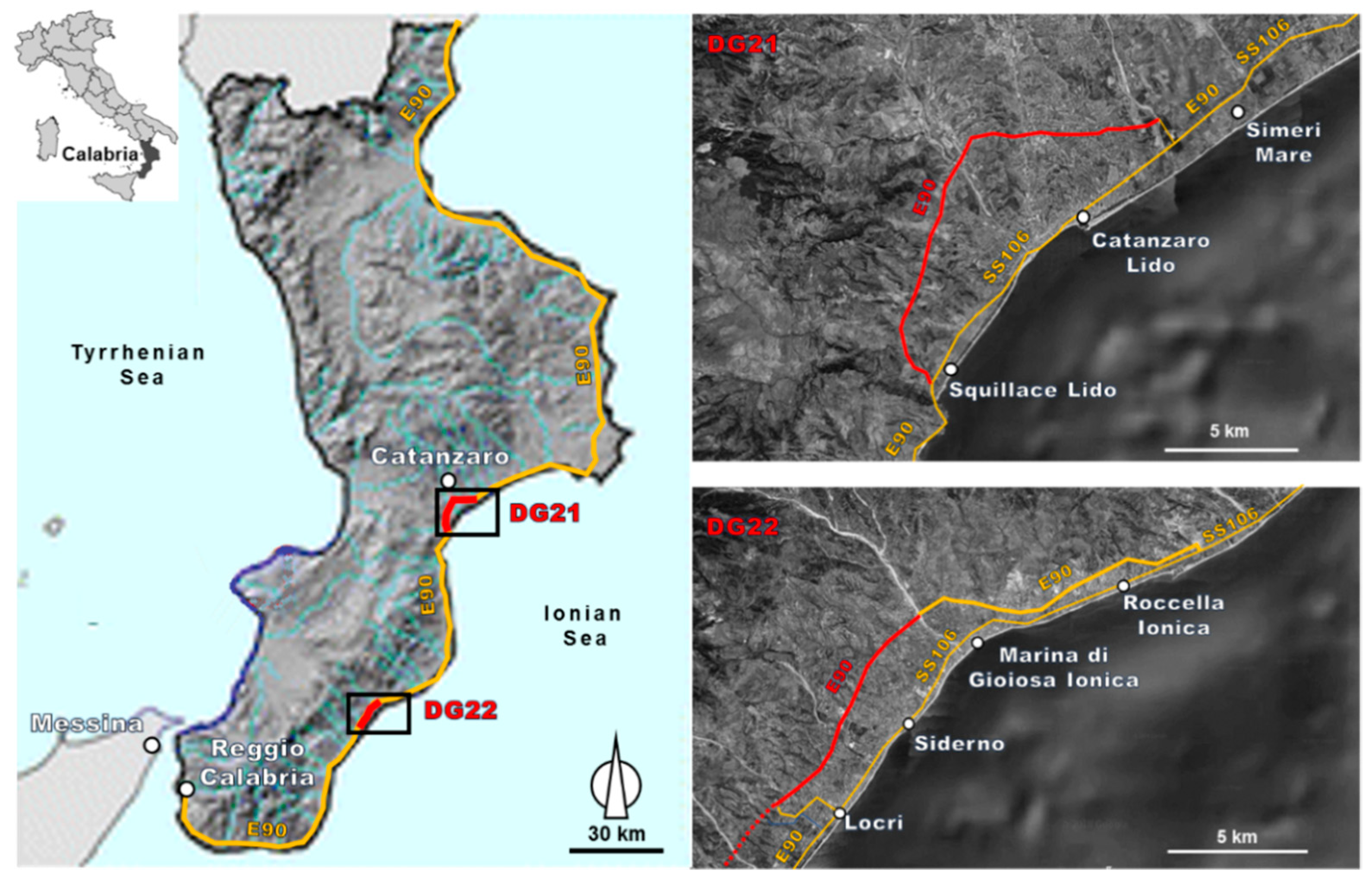
The map of the Calabria Region with indication of the two road segments of interest, named DG21 and DG22 maxi lots, is shown in
Figure 1. The first one, called the DG21 mega lot, is located close to the city of Catanzaro and covers a segment of 17.2 km, from the town of Squillace to the Simeri Crichi junction. The second one, called the DG22 mega lot, spans over a length of 16.9 km, from Marina di Gioiosa Jonica to Ardore, South-West the town of Locri, although, at present, only 11 km have been built. The new road is classified as a motorway, with separate carriageways for the two traffic directions, and improves present coastal roads in the vicinity of touristic locations where traffic is often highly congested.
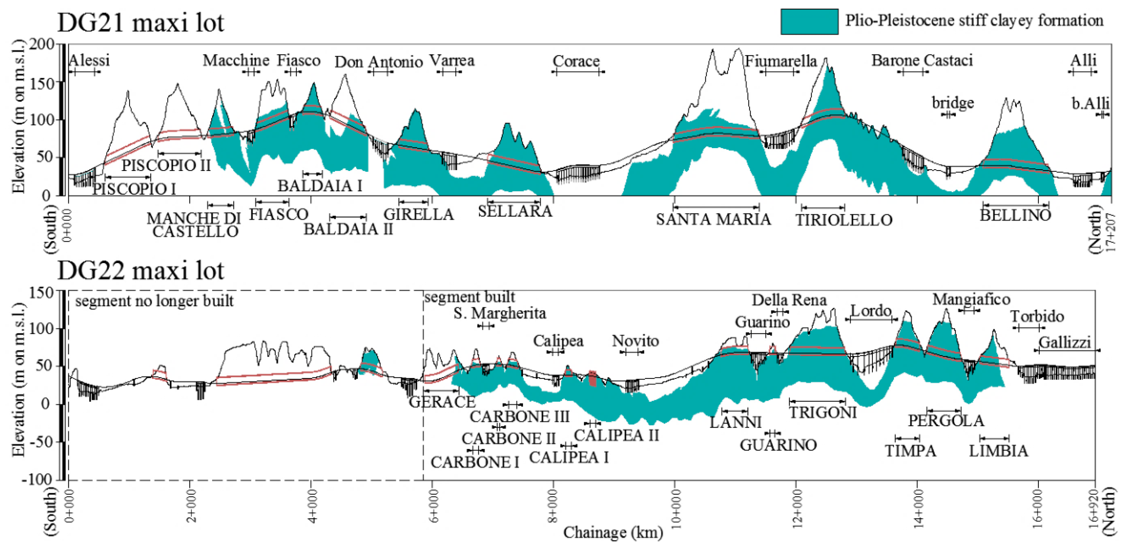
The most important engineering works for the DG21 mega lot include 11 twin-tube tunnels with total length of 7.9 km, 10 viaducts, 2 bridges, and 7 junctions; for the built segment of the DG22 mega lot, 5 twin-tube tunnels (total length 2.6 km), 7 “cut and cover” twin-tube tunnels, 7 viaducts and 3 junctions. Such works are outlined in
Figure 2 through simplified longitudinal cross-sections, with indication of viaducts, bridges, and tunnels for the DG21 and DG22 segments, respectively. In the figure, the diffusion of Plio-Pleistocene clayey formation is highlighted in color.
4. Design Strategies to Mitigate the Risk of Instabilities
Since it is clear that the kinematics of soil movements in stiff jointed formations is strongly conditioned by the geometry of the excavation, size and orientation of the cut surfaces in relation to the structural setting of the deposit, the amount of confinement exerted by the existing stresses, and the reduction of interlocking between soil blocks due to stress relief, the main design strategy should aim firstly at including the pattern of discontinuities in the geotechnical model. The definition of a reliable geotechnical model, in these cases, is essential, but not straightforward. For this reason, the comparison of the numerical results with sounding data from monitoring (i.e., data characterized by redundancy and coherence, see [
49]) appears to be the main strategy to assess the reliability of any geotechnical model, including complex formations. When the geotechnical model is a reliable representation of the reality, the dimensioning of the engineering structures can be appropriate and safe as well as the result of slope stability analyses.
Beside this main design strategy, two main approaches were found to be efficient for minimizing the risk of instabilities:
Below are presented solutions adopted in the construction of the DG21 and DG22 maxi-lots in which the previous principles have been put into practice either to restore safety after failures or to avoid the triggering of new instabilities.
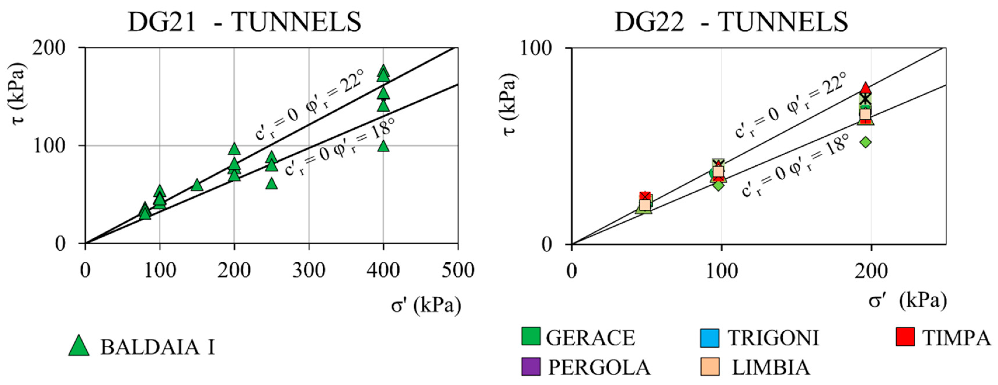
4.1. Design by Considering Discontinuity Patterns
In the following two examples, both referring to a slope in Plio-Pleistocene formation along DG21, the pattern of discontinuities was a key issue in the definition of the geotechnical model. With the first example, a case of slope stability analysis is presented; in the second one, the design of a retaining wall is discussed.
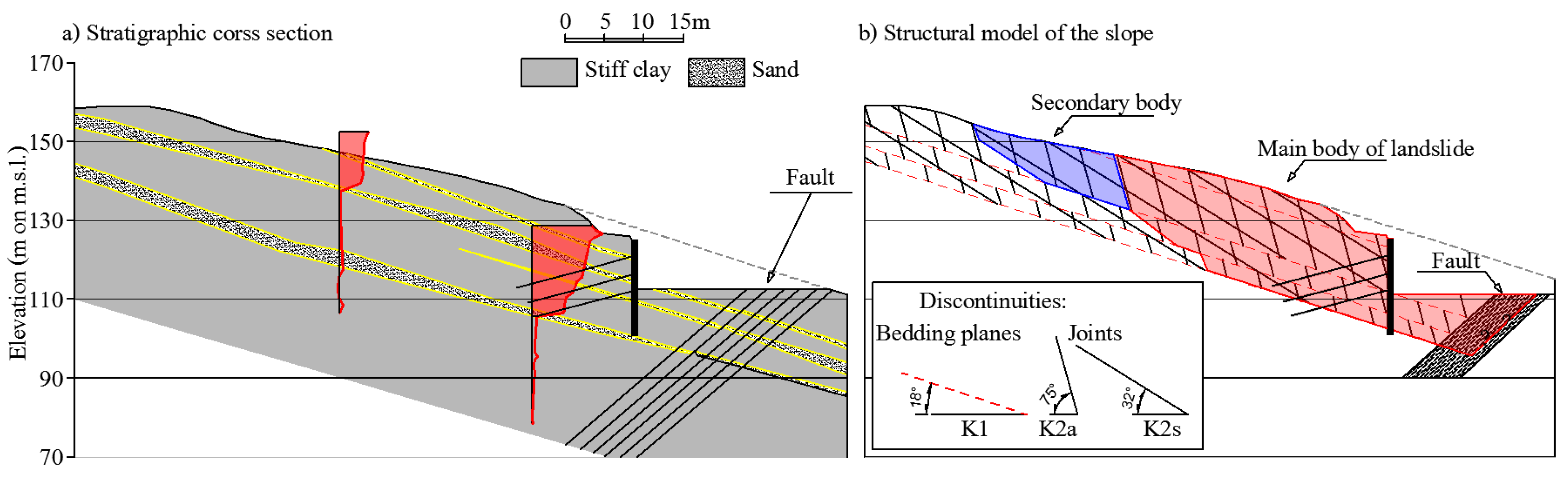
4.1.1. The General Stability of the Baldaia I South Entrance
The retaining structure protecting the southern entrance of the Baldaia I tunnel, a multi-anchored large diameter pile wall, suffered continuous horizontal displacements during ground excavation to reach the level of the tunnel base. The adding of several new ground anchors was ineffective to stabilize the geotechnical structure and the designer decided to temporary refill the excavation to stop such instability. A thorough soil investigation and monitoring results (see Scarpelli et al. 2013 [
30] for details) revealed that the structural features of the Plio-Pleistocene formation constituting the slope, characterized by a regular pattern of bedding planes, joints and faults, were controlling the kinematics of the phenomenon. In particular, the observation of Riedel Shear bands indicated a synorogenic stress state, that promoted the formation of polished slickenside surface of discontinuities where residual strength was attained. Here, it is of interest to show and discuss the adopted geotechnical model to design the reinforcing structures and evaluate the safety margin during the tunnel excavation.
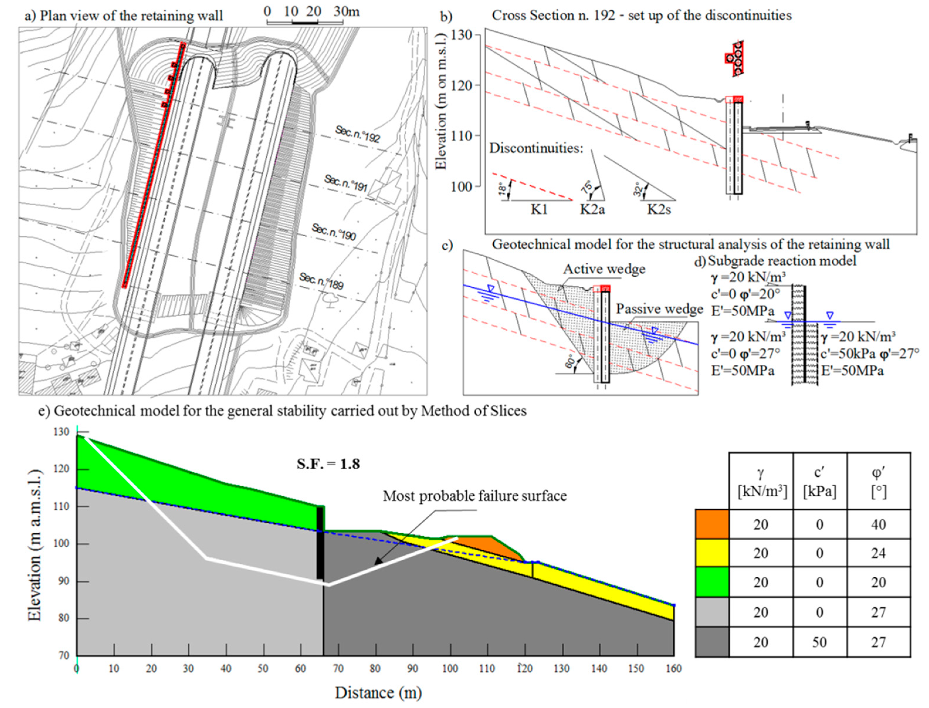
In
Figure 6a, a schematic representation of the cross-section of the slope in the area of the southern portal is shown with the most significative inclinometer profiles and the typical arrangement of the Plio-Pleistocene formation with the sandy layers sometimes included. The bedding planes are approximately parallel to the sloping angle, that is equal to 18°. At the toe of the slope a fault was detected dipping towards the slope itself. The fault had deformed and altered the geological setting in the area. In
Figure 6b, a simplified scheme of the structural model of the slope is given to bring to attention the two soil bodies involved in the instability. It can be observed that the displacement of the soil mass, evidenced by the inclinometers, takes place along the bedding planes.
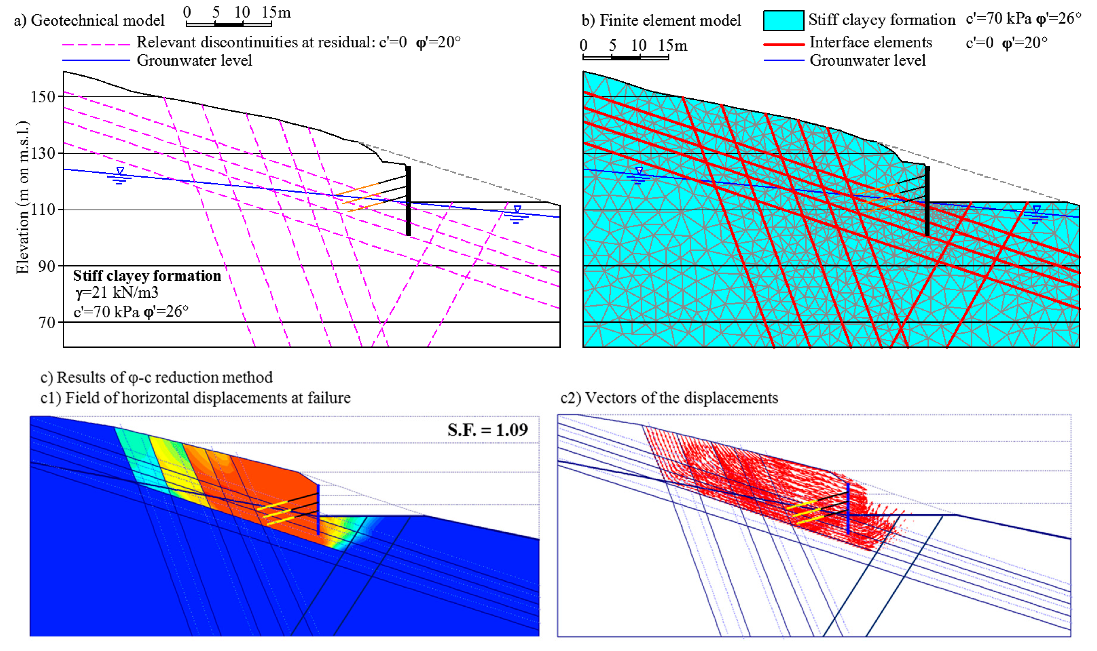
To design appropriate countermeasures to the instability, a numerical model able to reproduce the observed phenomenon was necessary.
In
Figure 7a,b, the reference geotechnical model and the correspondent calculation model for slope stability analysis are shown. It can be observed that the slope has been modelled as a uniform body of stiff clay interrupted by some discontinuities, which represent the main geological structures influencing the behaviour of the slope. The position of the groundwater level was determined by piezometer readings. Taking into account the presence of sub-horizontal drains from the retaining wall and the drainage exerted by the tunnel, it is reasonable to consider the groundwater level assumed in the model as stable in time. The slope was analyzed by means of a finite element model built with 15-node triangular elements and implemented through the commercial code Plaxis 2D (Bentley Systems, Inc., Delft, The Netherlands). The software allows the modelling of discontinuities as “frictional interfaces” where relative displacements (slipping/gapping) between separate parts of the mesh are admitted. The stiff clay was represented by means of an elastic perfectly plastic constitutive model with strength according to the Mohr-Coulomb failure criterion in terms of effective stresses, with cohesion c′ = 70 kPa and friction φ′ = 27°. Based on triaxial test results on undisturbed samples at an operative strain level, a Young modulus equal to 70 MPa and Poisson’s ratio 0.3 were assumed to characterize the elastic response of the model. Interfaces are characterized by a purely frictional behavior with an effective friction angle φ′ = 20°. This last value represents the residual strength along the discontinuities resulting from experiments. The numerical modelling of the slope was carried out in steps reproducing the in-situ initial condition, the construction of the geotechnical structure (retaining wall and ground anchors), and the progression of excavation. Failure of the slope was reproduced by a progressive reduction of the soil strength parameters according to the well-known φ-c reduction technique: a safety margin of 1.09 was obtained from the numerical analysis (
Figure 7c), thus confirming the close-to-failure condition of the real slope. Moreover, in
Figure 7c1, the field of horizontal displacements in the failure zone is highlighted. By analyzing the vectors of displacements (
Figure 7c2), the kinematics of the slope resulting from the modelling strongly resembles the picture emerging from inclinometer profiles, with a clear sliding of the blocks along the discontinuities. Having the numerical model given a sufficiently reliable representation of the deformation mechanism occurring at Baldaia I, it was possible to conceive and implement the necessary remedial measures. These aimed both at restoring the safety of the slope and allowing the completion of the works by means of a large filling at the toe of the slope to impede its movements. Considering that the filling substantially restored the original stress of the slope and that the formation is heavily overconsolidated, it is possible to exclude the development of excess pore pressures able to influence the stability of the slope. An elongation of the tunnel was first necessary, which was executed by adopting a “cover and cut” methodology.
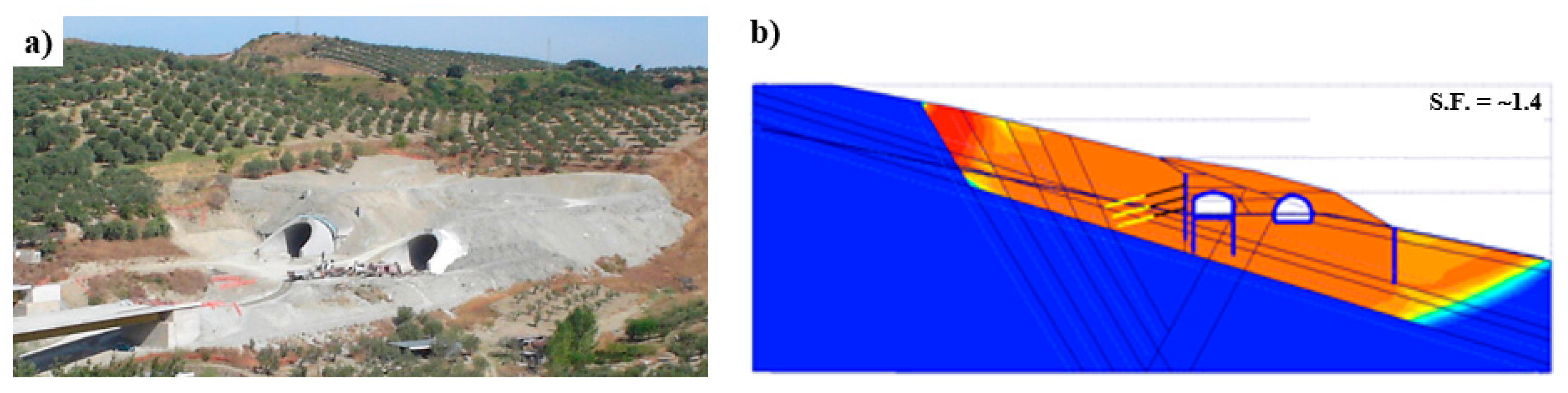
Figure 8a shows a picture of the Baldaia I southern portal soon after completion of the refilling.
Figure 8b shows the safety margin resulting from a failure analysis of a model of the slope that included the effect of the remedial measures. An increasing of the safety factor up to 1.4 was observed. It can be seen from
Figure 8b that the critical mechanism is much more extended than the one before the remedials and that the discontinuities involved in the failure are much longer, thus contributing to the increase of the safety margin of the slope.
4.1.2. The Retaining Wall between Fiasco Viaduct and Baldaia I South Entrance
On the same slope involved in the instability of the Baldaia I south portal, a reshaping of the ground profile was originally planned. Recognizing the strong influence of discontinuities on the response of the slope, it was then suggested that cutting into the ground was to be avoided (to keep the confining stress in the soil mass relatively high) and the new road was to be protected using an embedded retaining wall.
Figure 9a shows a view of the area with an indication of the new wall. For this particular case, the issue was how the pattern of discontinuities could be taken into account for a proper design of the structure. As shown in
Figure 9b, the slope is affected by three main families of discontinuities: bedding planes (K1), approximately parallel to the slope surface, and synthetic and antithetic Riedel shear planes (K2s and K2a, respectively). The geometrical arrangement of the discontinuities is such that the release of blocks against the wall at the active side becomes kinematically admissible. In facts, the combination of the K1 and K2 systems of discontinuities may clearly isolate active soil wedges uphill (see
Figure 9c), giving rise to a loading condition that is very dangerous for the structure. The situation on the active side is made worse by loosening of the shallow soil layer due to deformation of the retaining wall. A totally different situation is found at the passive side of the wall because the same pattern of discontinuities there becomes favorable. Therefore, even though the retaining wall interacts with a unique formation, the geometrical arrangement of the discontinuities requires to attributes different geotechnical properties to the various soil zones in contact with the wall (see Simpson 1992 [
50]). In particular, three different geotechnical models, each with its own set of parameters, were used to represent the same soil in the failure mechanism:
at residual (c′ = 0; φ′ = 20°) for soil at the active side above the excavation level, where the pattern of discontinuities favour instability and stress release is more pronounced;
at critical state (c′ = 0; φ′ = 27°) for soil at the active side below the excavation level, where the pattern of discontinuities is still unfavourable but stress release is limited;
at peak (c′ = 50 kPa; φ′ = 27°) for soil at the passive side of the retaining wall, where the pattern of discontinuities is such that the free movement of soil blocks is strongly opposed.
Here, the peak strength of the SJC-formation was assumed with a value of cohesion lower than that adopted for the analysis of the tunnels, to account for the much smaller volume of soil involved in the failure. In the geotechnical models, groundwater level was assumed at the bottom of the excavation due to the presence of a layer of sub-horizontal drains at that level.
In
Figure 9d, the subgrade reaction model adopted for pile design is shown. An operative Young modulus equal to 50 MPa was appropriate to account for the soil properties and the average strain level around the excavation.
In
Figure 9e, the geotechnical model used to evaluate the general stability of the slope after the excavation is shown. Note that the most probable failure surface was searched for by using the “block specified techniques”. This technique is a particular application of the Method of Slices in which the slip surface is divided into three segments and is suited for critical mode of failure when significative structural features of the ground or weak layers with known orientation are present, as in this case study.
4.2. Design to Limit the Stress Release
The following section discusses two examples, where the presence of stiff joint clayey formation at small depths with an unfavourable setting of discontinuities was faced by minimizing stress release induced by the excavation.
4.2.1. The Portal at the Southern Entrance of Timpa Tunnel
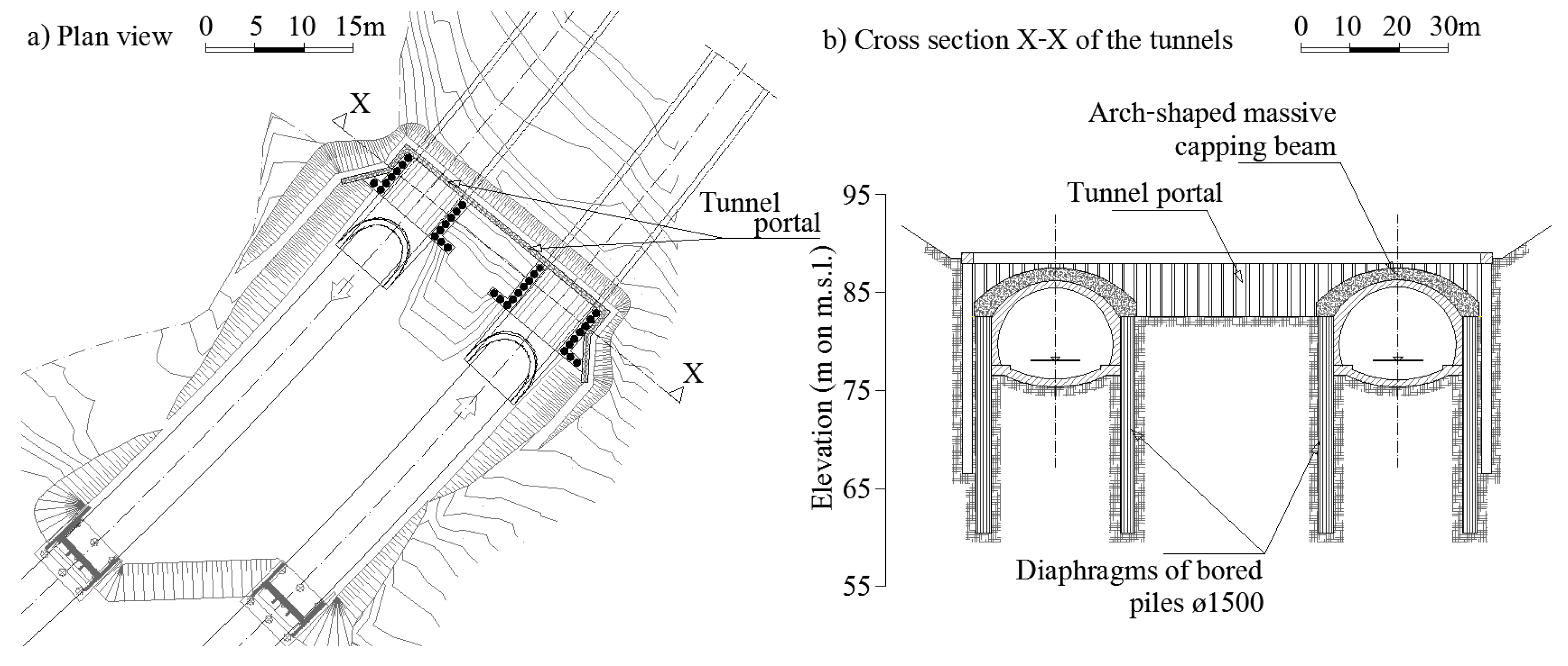
The excavation at the tunnel entrance when initiating underground works is always a source of stress release in the slope mass because of the inherent flexibility of the multi-anchored retaining walls usually protecting the portal entrance. With natural slopes in structured clayey formations, it is always advisable to limit the horizontal stress reduction. One possible solution is to implement a special application of the “cover and cut” method, that is the construction of a portal that will allow excavation of the tunnel exit. In particular, after the construction of the ordinary retaining wall, soil is pre-excavated only up to the crown of the future tunnel. Here, two diaphragms walls of juxtaposed bored piles are built along the sides of the future tunnel and are completed with a built-in place concrete beam on the top; the excavation is then backfilled up to restore the original ground level. In this way, tunnelling can proceed under the structural cover, without any pre-support system, just digging inside the tunnel lining. As the portal is a massive structure, the reduction of soil confinement is therefore strongly minimized.
This solution was adopted twice, namely at Baldaia I and Timpa south entrances. In both situations, the pattern of the discontinuities of the Plio-Pleistocene formation favoured instability. In the case of Baldaia I, intervention was executed to allow the completion of the tunnel after the occurrence of the instability phenomena previously discussed; at Timpa, construction of the portal was planned before the deepening of the soil in front of the retaining wall, as soon as signs of instability appeared.
Figure 10a shows a plan of the Timpa southern entrance, where it is possible to distinguish the bored piles of the tunnel portal from those built for the foundation of the massive capping beam. In
Figure 10b, a cross-section of the tunnels with highlighted components of the portals (diaphragms of bored piles ø1500 and arch-shaped massive capping beam) is shown. It is evident from the figure that this solution allows to reduce the span of the excavation at the tunnel entrance from about 15 m to 5 m.
4.2.2. The Pre-Support Intervention at the Gerace I Tunnel
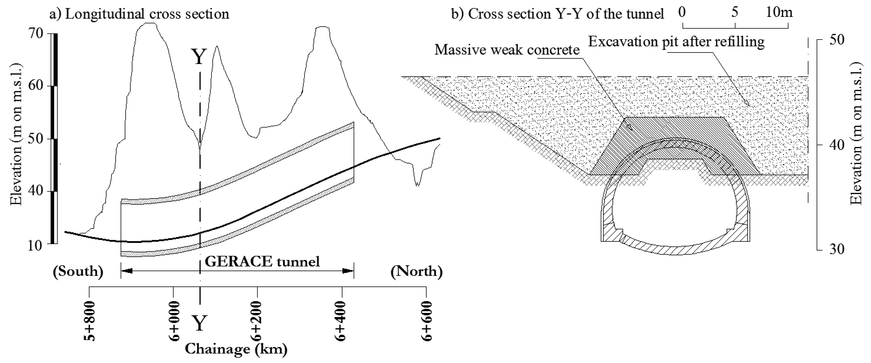
The Gerace tunnel intersects three little hills for a length of about 450 m (see
Figure 11a). At a chainage of 6+100 km, the tunnel crosses the lowest point of a steep valley, with minimum cover of 6–8 m. This segment was particularly sensitive due to the low cover that impedes the full development of the arching effect. In this condition, designs typically provide a strong pre-support intervention using the fore-pole umbrella system. The designer, however, proposed to carry out a reinforcement of the soil above the tunnel crown. As shown in
Figure 11b, the reinforcement consisted of a large excavation up to the shoulders of the future tunnel and the construction of a massive block of weak concrete set-up to reproduce the shape of an arch segment. The excavation was then refilled with soil up to the original ground level. The methodology adopted as a preventive outer support allowed efficient and safe progression of the tunnel excavation; however, the environmental impact is significant and the excavation along the entire valley is only possible in the absence of buildings or river channels in the zone of intervention.
4.3. Ground Improvement by Rigid Inclusions: Example fom Trigoni I Southern Entrance
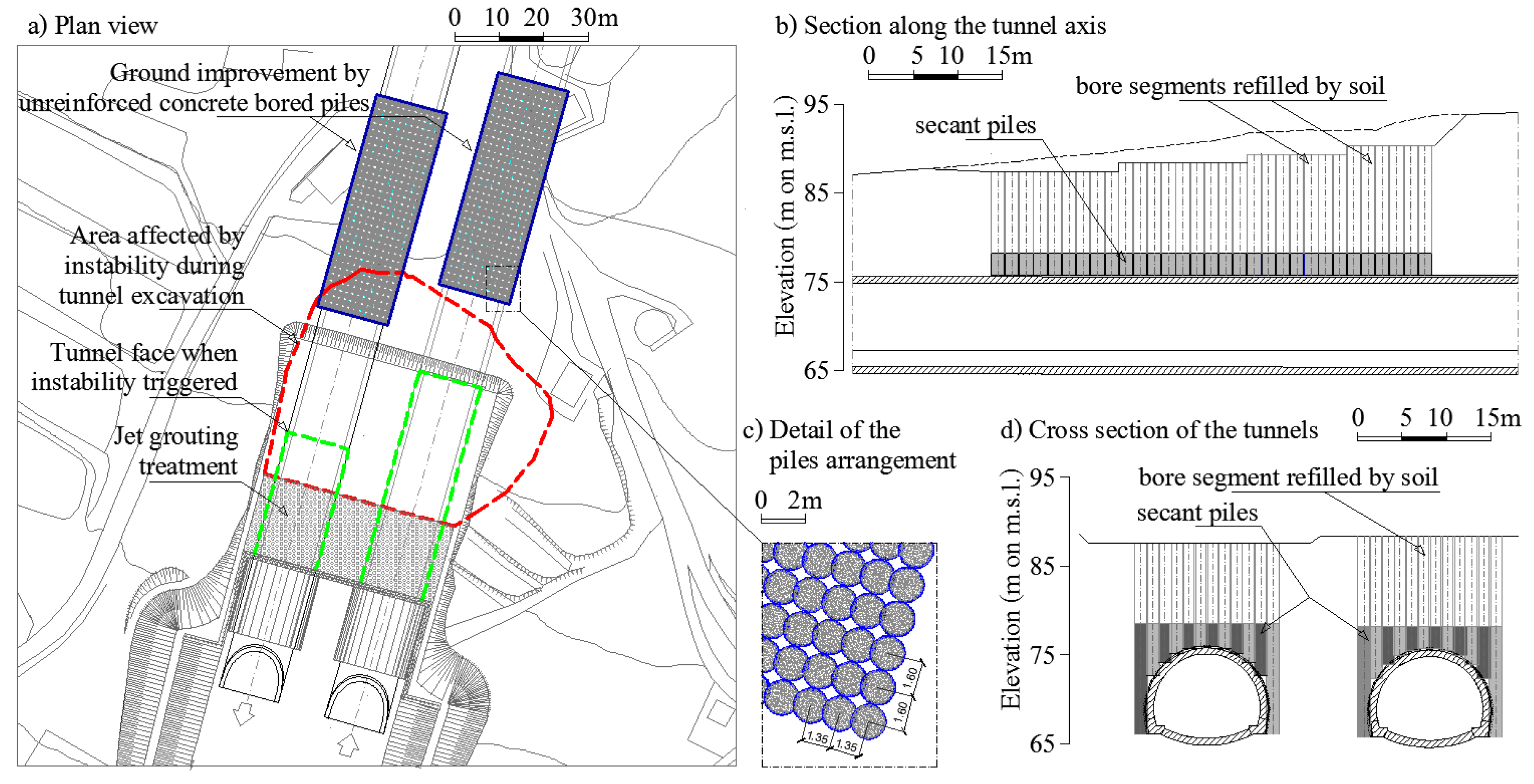
Ground improvement by rigid inclusions is a technique sometimes used to reinforce the ground before execution of a tunnel in structured formations. The possibility of working from outside, as offered by this technique, is particularly convenient, because it is known that costs of underground activities are several times higher than those of ordinary works. Minimizing expensive underground works ensures wide economical margins for the implementation of extensive treatments from the outside. A good example of application of this technique is the ground reinforcement carried out for the southern entrance of the Trigoni I tunnel along DG22. Difficulties in excavation were anticipated because a thick, incoherent Quaternary deposit lied on the Plio-Pleistocene formation at the tunnel entrance. In this particular case, jet grouting treatment of the incoherent soil helped overcome the difficulty, and subsequent excavation proceeded within the Trubi formation, with an average ground cover of about 10 m. To allow the excavation, the designer prescribed a primary lining made of an open ring of reinforced shotcrete (0.2–0.3 m thick) and steel cradles (2 coupled I bars IPN220 each 0.75 m). An umbrella of 48 sub-horizontal fore-poles over the tunnel crown and 60 fiberglass dowels were used as stabilizing measures at the front. After excavating some tens of meters, an instability phenomenon occurred, probably caused by the yielding of the soil pillar between the two tunnels. As indicated in
Figure 12a, the instability involved both the tunnels and propagated up to the ground level, where tension cracks and huge settlements were detected. The cause of the failure was related to the arrangement of the discontinuities that affected the Pliocene-Pleistocene formation. Details about this event can be found in Segato et al. (2015) [
31]. To overcome this second drawback, a ground improvement intervention was adopted, whose geometrical characteristics were such that an “arching effect” was activated. As shown in
Figure 12c, the ground reinforcement consisted of a number of unreinforced concrete bored piles, 1.5 m diameter, arranged in square array 1.35 × 1.60 m. Only the segment of the bores close to the tunnel lining was concreted, whereas the remaining portion was refilled by soil. The piles were secant along the transversal cross-section to form a structural massive arch above the tunnel with thickness of 2–3 m. Moreover, as shown in
Figure 12b,d, by varying the length of the piles, a complete shell around the crown was shaped, which included the shoulders and sidewalls of each tunnel. After the treatment, the underground excavation proceeded quickly with a relatively light primary lining consisting of an open ring of reinforced shotcrete (0.2 m thick) and steel cradles (2 coupled I bars IPN180 each 1.20 m).
5. Conclusions
The geotechnical design of linear infrastructures in structurally complex formations is always a difficult task and many professional profiles, geologists, engineers, public administrators, and construction experts have to be involved to reach a good balance between the risk of unexpected events and the large costs of preventive measures. In this context, the presentation and discussion of design experiences from real case histories appear particularly useful—the technical community shares knowledge about possible solutions for similar circumstances.
This was made possible by the construction of two new segments of highway along the Ionian coast of the Calabria region in the south of Italy. Several tunnels and excavations were built in Plio-Pleistocene formation in the area, typically classified as a Stiff Jointed Clay (SJC). A general finding, from the presented examples, is that the mechanical response of the SJC formation strictly depends on the setting of the discontinuities, a typical consequence of intense geological vicissitudes and along which shear strength is often close to the residual value, that is, the lowest possible strength. A careful evaluation of soil residual strength is, therefore, extremely relevant for interpretation and modelling of instabilities in SJC formations. Although the safety margins implied by technical standards are quite high, designers should be aware that such margins may be completely inadequate to stop the triggering of instabilities along discontinuities, especially those that are not anticipated and detected during design.
An early investigation of discontinuity patterns is, therefore, the most important preventive measure to minimize the risks of instability of slopes, excavations, and underground constructions in geologically complex formations, although the identification of discontinuities is made difficult by the presence of weathered soil layers typically covering such formations. To overcome this limitation, when geologic structures such as faults are expected from the general character of the formation, it is suggested that natural and artificial exposures are observed and exploratory trenches are used.
When the discontinuity pattern is identified, its relevance for the geotechnical problem at hand has to be analysed. This typically implies a consideration over the adoption of a continuous or discontinuous description of soil volume in the zone of influence for the specific geotechnical work. This evaluation is not trivial, as it is well known in rock engineering design, and is a fundamental issue to be addressed for assessment of the proper geotechnical model. For intact rocks or heavily jointed rock masses, an isotropic-homogeneous continuum can be a good representation of reality. On the contrary, when the size of the blocks isolated by the discontinuities is comparable with the dimension of the geotechnical structure to be designed or when a discontinuity set is significantly weak, the geotechnical model should be discontinuous, so that the weak surfaces are explicitly introduced in the model and any possible failure mechanism is analysed in the light of the structural features of the complex formation.
Several interventions have proven effective in avoiding possible slope instabilities. There have been instances where geotechnical design has aimed at minimizing stress release in structured soil mass, thus preventing failure by increasing the kinematical constraint of the soil blocks. The following construction techniques may be ascribed to this category: tunnel construction by means of the cover-and-cut method, pre-support works by massive soil treatment, and ground improvement by rigid inclusions. All of the previous techniques imply the use of large amounts of construction materials (concrete, steel) that have a huge negative impact on the environment. Thus, a cost-benefit analysis then becomes necessary. In the case of tunnel construction, the adopted methodology allows underground excavations in zones where soil cover is particularly small (5–15 m above the tunnel crown), where the arching effect cannot develop and failure is mostly probable.
Last, but not least, the general conclusion is that a close collaboration between structural geologists and geotechnical engineers is vital in implementing a reliable geotechnical model from the very beginning of the design, that is, a model that includes the main structural features of geologically complex formations and allows the conception of preventive measures to minimize risks of slope failures and construction costs.


