Abstract
Buttresses constitute a spatial supporting construction (SSC) that can convey large loads coming from the pressure of unstable soil on deeper, more stable layers to make it safer with respect to the load-bearing capacity. They make the counteraction against the pressure, which initiates sliding when the forces to move the landslide body, not balanced by the internal frictional forces in the soil. Some specific features of known construction elements were used in the buttress, such as sheet pile walls and drilled piles. Although beneficial in this case, the specific shape of the axis of the wall made from piles and sheets formed a wave created from circle sections (in plan view). Thus, a stable steel buttress was formed. The interaction of the buttress with the soil mass pressure over it, which stabilises the landslide mass, was considered. To further strengthen the buttress, a reinforced concrete slab was added on the upper edge of the thin walls of sheets and piles, thereby integrating and stiffening the whole structure. The application of the concrete slab enabled the use of the stabilisation role of additional forces (become from its weight and above laysoil)to stabilise the buttress. The results of this study achieved a substantial stabilising effect, increasing maximal forces reacting against the pressure of the unstable soil block. Assumptions madeand the applied calculations confirm thestability of the buttress (by increasing the stability of the whole slump block of landslide) are described. Two cases are presented to illustrate the stabilisation and control of movement in which the block body moves along inadvance of the determined slip surface.
1. Introduction
The knowledge of the landslide risk is not common enough in society. Some people, and in some cases, designers of earth structures are not fully aware of the scale of this risk.Gunther et al. [1] analysed landslides on the basis of geotechnical data from different European countries. Landslides occur in the mountains and foothills of the Alps, Carpathians, Pyrenees, and Balkans, but they can also be found in other areas. In fact, few regions can be defined as free from risk [1]. Issues of scarp and slope stability are treated superficially in many cases, without due care and diligence. Many factors can trigger landslides on natural slopes. In some cases, engineering interventions to prevent or control landslides did not produce the expected results. Examples of incorrect protection of a high slope were described by Akin [2] who constructed water storage tanks of different capacities, one under the other, on closely-jointed and deformed shale and sandstone units. The upper tank was constructed first and a 20 m cut slope with two benches was excavated in front of the upper tank before construction of the lower tank. The cut slope failed after one week, and the failure threatened the stability of the upper water tank. In this case, the buttress protecting the water reservoir was built on a slope of the soil of shale with sandstone layers. The buttress was made of large reinforced concrete piles in a wall-type construction 15.6 m deep and crowned with a reinforced concrete-retaining wall with no anchor. Because this method did not produce satisfactory results, it was necessary to add an additional massive soil buttress, which diminished the overall steepness of the slope. The most important conclusion from this case study is that the application of the correct technique is key to avoiding damage caused by engineering constructions.
Similar conclusions can be drawn from studies by Day [3] who demonstrated that, in addition to selecting a relevant method to support a scarp, it is also crucial to locate and shape the buttress correctly. The case described in this study presents efforts to control the slope threatening a housing estate located on a hill. The earth buttress constructed at the base of the landslide stopped the old, many-years-lasting slide. However, after 16 years, the landslide reactivated. Only the rebuilding of the buttress finally allowed for control of the landslide. Reactivation of landslides is acommon phenomenon, especially with respect to old long-lasting landslides with slow velocity movements. The movement of these landslides is an irregular process that sometimes undergoes rapid accelerations. A direct initiator of landslides can be an impulse in the form of seismic tremors or a passing train [4,5], but the most important triggers are changes in the levels of groundwater and the impact of surface water and runoff. Many studies on slope stability demonstrate that the infiltration of rainwater onto a slope diminishes its stability. Gasmo et al. [6] demonstrated, through numeric modelling, a strong relationship between slope stability and infiltration of rainwater. Under the model conditions, it was determined that desiccation of soil increased slope stability by 30% and precipitation with an intensity of 80 mm/day decreased slope stability by 25% within 12 h. This confirms the potential for an abrupt increase in the risk of slides directly after long and intensive atmospheric precipitation.
In addition to selecting an appropriate method of landslide stability, knowledge of the geological structure and composition of the rock mass is important. The potential for landslides to damage engineering constructions is considerable, and the problem has been studied and described in many articles [7,8,9].
Among the many types of landslides [10,11,12] in my research, I focused on those which constitute more complex problems due to their character. According to the modified landslides classification [12], there are 32 landslide types. Each of thesetypes is backed by formal definitions and examples. Complex landslides are not included as a separate category type, but composite types can be constructed of the classification by combining more type names. The landslides which are the object of my interest are the clay/silt planar/compound slide according to this classification. They are a kind of structural type landslide (i.e., the ones in which the translational slide of soil mass occurs along the surface that occurred the rupture). This surface is the natural arisen border between landslide bodiesand the stable original soil. Difficulty in controlling these landslides depends on whether a stable base for mounting and anchoring buttresses exists. Such examples were presented by Brencich [13] for the stabilisation of a highway section and Azm et al. [14] for the stabilisation of a tall building located on a slope. The reason for the catastrophic results produced by this type of situation is that, in general, the endangered structure is not anchored to the stable part of the rock mass. The part of the slope becomes detached from the undisturbed soil below and moves downslope alongthe basal contact of the slide surface. This surface is usually plasticized on top of a slit or clay layer. Such landslides arise commonly after heavy rainfalls, with the supply water going to the contact layer (basal detachment fault).
Beben [15] and Liao at al. [16] analysed construction in which cylindrical structures comprising steel sheets and piles were considered, taking into account the double role of soil as an element supporting and weighting down the construction. This problem was also discussed by Farzaneh et al. [17] and Hajiazizi and Mazaheri [18], and the problems in the calculation were similar to those presented for complex steel, concrete, and soil constructions.
Each of these cases demonstrates that the control of landslides is an engineering problem that has not been enough solved until now. Previous solutions have several discrepancies which limit their application, including:
- (i)
- applied solutions were based onthe massive buttress,
- (ii)
- in the case of application of buttresses on the landslide forefront, there is a large scale of works in the place where the landslide body reaches the largest dimensions,
- (iii)
- in the case of application of anchors, difficulty in obtaining stable anchoring in some soils and/or weathered rock layers, and
- (iv)
- the occurrence of rivers or streams along the base of slopes will hasten the erosion of the landslide forefront and render it impossible to construct an effective buttress in this location.
This paper presents a new method of countermeasures to mitigate the risk of landslides. In the analysed cases, spatial supporting constructions (SSC) can be applied. A novel SSC comprised of steel, reinforced concrete, and soil was examined and required elaboration of an individual method of balance analysis. To verify presented below accepted assumptions, the following analyses were conducted:
- (a)
- analysis and selection of a new SSC, eliminating faults of constructions used until that time for control of landslides with determined slide surface,
- (b)
- analysis of methods of theSSC static equilibrium based on the limit equilibrium method (LEM),
- (c)
- analysis of landslides using elaborated methodology and design of the shape of the SSC,
- (d)
- verification of accepted assumptions for calculation on observations of actual buttresses constructed using the SSC method and stabilisation of landslides on state road 8 in Poland, and
- (e)
- monitoring of landside stabilisation based on geodetic measurements of slope focused on the road and slope base.
This publication presents general assumptions of SSC stability analysis based on examples of constructions of the SSC type executed and checked in situ.
2. Description of Landslide Stabilisation Method with Application of Spatial Supporting Construction
There are many ways to stop and prevent landslides as described in the introduction. One type of these methods is the application of various types of buttresses and retaining walls. To increase effectiveness, buttresses should be massive and/or additionally anchored. These are simple and effective solutions. However, the simple approach is not always possible. One concern, among others, is that landslides often form in relatively shallow (5–15 m) surface layers of a slope, under which there is usually a stable base (e.g., hard rock covered by alluvium). In this case, the buttress should be constructed at the base of the landslide; however, this is not always possible, especially when there is a river at the base of the slope that constantly erodes the forefront of the landslide, making it is necessary to look for other solutions. In addition, when the base on which the landslide moves is weathered and/or cracked (e.g., shales), it becomes unsuitable for anchoring, making it is necessary to construct an SSC to stabilise the slope. It should be remembered that the construction of the buttress in the form of a retaining wall is not always possible on an active landslide. Moreover, digging of a buttress trench could cause disturb the unbalanced equilibrium at the soil.
The proposed solution of a buttress in the SSC form fulfills the requirements mentioned above. The solution constitutes a buttress, whose characteristic feature is the ability to transfer large pressure loads by pressing the base of the SSC (0.5–1.5 m) into a stable and strong base. The described SSC enablesthe joining of the stabilised landslide debris and the ballast supporting the buttress. A buttress shaped in proposed form from thin-walled steel profiles serves in this case as a massive buttress as depicted in Figure 1. The buttress may be located anywhere on the slope without disturbing the stability of the soil during construction.
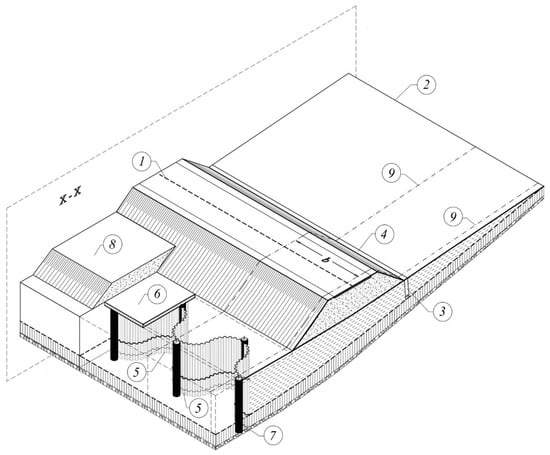
Figure 1.
The axonometric view (with openings) of a section of landslide stabilised with a spatial supporting construction (SSC): 1—Road on embankment; 2—Outline of upper edge of landslide; 3—Principal drain pipe for dewatering the slope was installed in sheet piles; 4—Surface water intake; 5—SSC with tight walls of steel sheet piles; 6—SSC with slab of reinforced concrete (wale slab) uniting buttress elements; 7—SSC with the steel pile supporting the buttress; 8—SSC with wale slab ballast to load buttress; 9—Edge of separated slump block fragment, for which the b width SSC module stability analysis was conducted; X-X is the cross-sectional plane oriented along the directionof landslide movement.
The SSCs proposed in this study were made from basic elements: steel sheet piles and concrete slab wales. The use of these elements in the correct shape make it possible to construct buttresses able to transfer to the stable subsoil very large forces caused the landslide’s mass pressure. The technical possibility of forming curvilinear steel sheet piles thanks to the leeway of their connectors was used. Thus, a spatial shape of the buttress was accomplished (in map view this forms a wave created from semicircles approximately 5 m in diameter), enabling it to counteract forces many times larger than the soil pressure as compared to a wall formed as an even plane. Moreover, the SSC does not require driving the walls deep into the base soil as is necessary when plane walls are used for support because the pile wall forms an SSC with much higher rigidity. In addition, the soil mass lying over the slab of the buttress increases its efficiency by increasing the forces retaining the slump block while maintaining the sliding forces. Such buttresses applied in practice fulfilled their role in controlling some landslides. Actual examples of realisations are presented in Section 4.1 and Section 4.2. Application of this solution required relevant analysis enabling us to consider the influence of the slab ballast on the stability of the buttress, which caused the landslide mass stopping. Such an analytic approach tothe problem is presented in the study.
3. Analytic Approach to Stable Supporting Structure in Stabilisation of Landslides
3.1. Assumptions Used to Calculate Stability
Buttress-made tight wallsfrom the sheet piles have been used for a long time; however, their application in the present case makes it possible to shape them in a way that improves buttress stability. Established methods of calculating stability and strength of tight walls were applied [19,20]; however, methods of sheet pile forming along a wavy line (in map view) engages both the landslide soil slump block adjacent to the wall and the slab (topping the upper edge of the wall) with thesoil located over of this slab. The bottom of the wall, which is dug into the stable (usually solid) base, attaches the whole construction preventing wall and landslide movement. The general way of taking into consideration the reaction of the pile wall in calculating SSC for landslide stabilisation is shown in Figure 2 using the landslide example presented in Figure 1.
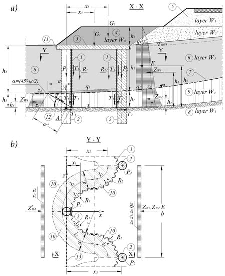
Figure 2.
Diagram for calculating the equilibrium of a landslide slump block along a section of a single SSC module: (a) Road and SSC cross-section (part of X-X cross-section from Figure 1); (b) Y-Y cross-section of a repeatable SSC part (module) of length b in plan view (under the wale slab); 1—SSC of the wall using steel sheet piles; 2—SSC of the supporting steel piles; 3—SSC of the reinforced concrete wale slab; 4—SSC of the ballast loading down the wale slab (W6 is soil or gravel, etc.); 5—Road on embankment (W1); 6—Landslide body (layers W1, W2, W3); 7—Slide surface; 8—Stable base (W5 comprises tight solid soil or rock); 9—Top layer of stable base (W5 comprises tight solid soil or rock alluvium); 10—Zone of shear stress varies in the load-bearing layer of soil W4, caused by the pressure of the sheet pile wall; 11—Assumed surface of the crevice separating the soil from the buttress; 12—Location of the surface of the potential load-bearing layer of soil by shearing of the sheet pile wall; 13—Axis of potential SSC rotation (passing through point A).
Figure 2 presents the diagram used to calculate the equilibrium of the landslide slump block (width b corresponding to a single SSC module), in which the following symbols are used:
- r—radius of curvature of sheet pile wall,
- h1 ÷ h5—thickness of individual soil layers,
- h6 ÷ h9, x1 ÷ x5—distance of resultant forces from revolution axis of the SSC,
- A—hypothetical SSC revolution axis (marked as a point on the X-X cross-section),
- q1—stress caused by weight of soil layer on the sliding surface (constituting part of the landslide mass),
- qE—unitpressure of landslide on the SSC as determined by the LEM,
- za, zb, zc—unit of active pressure of soil together with the water pressure reacting on the SSC,
- zd, ze—unit of soil resistance reacting on the SSC,
- E—resultant force from the landslide pressure on the SSC (not balanced with internal frictional forces of the rock mass) determined by the LEM method,
- ZW3—resultant force (for a single SSC module) resulting from active pressure of soil forming the landslide (layer W3) and the water pressure on the SSC,
- ZW4—resultant force (for a single SSC module) due to active pressure of soil in layer W4 (under the sliding surface) and the water pressure on the SSC,
- —resultant force (for a single SSC module) due to resistance acting on the SSC by layer W4 (under the slide surface). The values of these forces were determined in the following way:
- R1, R2—resultant forces due to soil friction against the wall of sheet piles surface and the weight of the wall of length l1 superimposed on its centre of gravity and determined according to the following relation:
- Rs—force from the weight of the tight steel pile wall on a section of length of l1,
- qs—unit weight for 1 m2 of tight steel wall (in the wall axis plane),
- hs—the total height of tight steel wall—average of the module,
- l1—length of steel pile wall section calculated along its axis,
- T3, T4, T5, T6—frictional forces in soil against the wall calculated according to the assumption used to determine lateral surface resistance over a large diameter field according to Polish standard [19]:
- t—soil strength along the wall surface as determined on the basis of limit strength falling on 1 m2 of wall area (determined according to the principles presented in Polish standard [19]) for the lateral surface of the pole located at depths below 5 m). The above assumption is correct as evidenced by the occurrence of very high pressures in the soil on the wall.
- βs—dimensionless factor (ratio) of sheet piles area to total wall surface area, calculated along its axis (the value is a function of the type of sheet pile, 1.2 ÷ 1.5),
- P1—the sum of forces from the own weight andcapacity of the pile on the pressure exerted on the stable base soil,
- P2—the sum of forces from the own weight and capacity of the pile on the zone W4 below the slide surface,
- G1, G2—weight of wale slab and ballast bank, respectively,
- T1, T2—shearing forces at the base of pile sheets considering the strength of the wall on both poles,
- T7—maximum shear force which the soil can resist in layer W4 caused by pressure on sheet pile wall,
- a—width of soil resistance zone in layer W4,
- a’—width of potential soil shear force on the surface due to the pressure of the wall (after surpassing of soil resistance),
- l2, l3—length of specific surfaces of soil resistance,
- α—inclination angle of potential soil shear surface due to the pressing wall,
- Ψ—transformed angle of internal friction in the tight soil (considering, apart from effective internal friction angle also effective soil cohesion). This parameter results from the Mohr-Coulomb criterion according to Labuz and Zang [21] and Wilun [22]:
where:
- τ—shearing tension,
- ϕ’—effective angle of internal friction,
- c’—effective cohesion,
- σ’ = σ − u—effective stresses in the solid phase at the moment of shearing,
- u—pore water pressure in a sample at the moment of shearing,assuming thatwe derived
Meanwhile, for soils without cohesion (c’ = 0), it is possible to assume that
Conducting calculations to check the stability of the SSC requires acceptance of a few principal assumptions, i.e., soil pressure makes forces pushing down on the landslide body act on the surface of sheet pile wall and they originate from:
- landslide pressure on the SSC as determined by the LEM method (force E),
- pressure of active soil in the landslide body(ZW3), increased by water pressure, and
- pressure of active soil under the sliding surface(ZW4), increased by water pressure.
Analyses of shear resistance parameters in soils forming the sliding surface account for the peak and residual resistance of soil saturated with water. Research was performedusing methods that simulate conditions to achieve residual sheer resistance in the soil. These parameters were used in the made calculations.
Each analyzed geotechnical cross-section through a landslide requires an analysis of the pressure distribution resulting from water pressure, which has a significant impact on the pressure in the soil pores. In the analyzed cases, the need to determine the impact of the pore pressure on the landslide body was narrowed down to the identified slip surface and its immediate vicinity. The pore pressure in the slip surface and in the ground layer just above it determines the stability of the entire body of the fraction. Therefore, soil samples were analyzed taking into account the broadly defined range of possible pore pressure values of this contact layer. Thanks to these tests, the extreme soil parameters of the contact layer were distinguished, and based on them, a stability analysis of the landslide body based on LEM was performed. Not all LEM analysesof the landslide, as a separate moving body, are described in this paper. They can be found in other articles [23,24]. Thus, the pore pressure was included in the soil parameters of the sliding layer in previous analyses and this is reflected in the E force. In the presented paper, I focused on the stability of the SSC as the meansto improve the equilibrium conditions of the landslide. Therefore, the pressure of groundwater, adequate to the expected maximum level of groundwater after the execution of the SSC, was taken into account. This was included in the forces za, zb, zc and ZW3, ZW4 constituting the load from soil pressure and water on the SSC. Therefore, the role of water on vertical and horizontal stresses was taken into account in calculations of: (i) horizontal effect of water action was included in ZW3 and ZW4 forces and za, zb, and zc stresses, (ii) vertical effect of water action was included in the analysis of all landslide bodies according to the unit weight of natural and saturated soils.
On the other hand, counter forces counteracting the revolution of the SSC originate from:
- (i)
- the weight of the steel pile wall Rs,
- (ii)
- frictional forces in the sheet pile wall caused by soil pressure on the wall and its counteraction T3, T4, T5, and T6,
- (iii)
- weight of piles and their capacity to press on the stable soil P1,
- (iv)
- weight of piles and their capacity to force layer W4 from out below the slide surface P2,
- (v)
- weight of the wale slab and ballast bank located on this slab G1 and G2, respectively.
The forces counteracting the effect of gravitational sliding on the SSC are caused by:
- (vi)
- counteraction by the stable base ,
- (vii)
- resistance to shearing of piles at the base of sheet piles driving T1 and T2, and
- (viii)
- resistance to shearing of the top layer of the stable base (Figure 2a item 9), in which the sheet pile wall is supported throughthe soil T7 being pressed against.
Vertical forces tangential to the wall side surface and piles (from the de-aerated side) and the counteraction of soil in the landslide mass were omitted (a possibility of fissure formation between the soil and wall (above the slide surface) was assumed and is illustrated in Figure 2a item 11). Accepting these assumptions and geometrical parameters of the SSC and static values acting upon it, the static conditions of a potential or active landslide supported by the supporting structure were determined (Figure 1) and weredescribed in Ukleja et al. [25]. In the beginning, geotechnical, geoengineering, and hydrologic conditions and soil strength parameters within the stabilised landslide were determined. Then, using the LEM method (e.g., the 3D slump block analysis method presented in Ukleja [23]), the pressure force was determined as force E unbalanced by the internal friction forces of the rock mass. This constitutes the difference between the resultant of restraining forces and forces pushing the slump block along the whole width of the stabilised landslide. Determination of this force was necessary to balance it with the design of the SSC. Depending on the values of the calculated retaining forces on particular sections of the landslide slump block s, relevant modules of the SSC were selected (see Figure 1 and Figure 2b, in which the dimension b determines the module width). The SSC should be designed to provide the required stability of the landslide fragments (for all of the SSC modules).
Adapting the capacity of the SSC may be accomplished by the introduction of the following changes:
- (a)
- degree of curvature on the wall plane (Figure 2b, dimension r),
- (b)
- depth of pile setting as a function of the bearing strength of the base located under the slide surface, and
- (c)
- diameter of piles and method of shaping their feet (e.g., widening the pile foot).
In order to simplify calculations, it is beneficial to divide the slump blocks with vertical planes the length of the SSC modules and parallel to the direction of landslide movement. Cross-sections across the slope and landslide were made on these planes. The span of these planes corresponds to module width b (Figure 1 and Figure 2b).
Calculations based on the above assumptions of the state of equilibrium of particular sections of scarps and slopes influence the efficiency of the SSC. They refer to landslides moving on the sliding surface as determined by the system of layers and types of soil as well as potential landslides.
The stability analysis of the SSC required the following course of actions:
- The magnitude offorces resulting from unbalanced pressure of the sliding section wasdetermined for individual modules of slump blocks with the LEM method, using one of methods for instance method presented in [24].
- The magnitude offorces wasdetermined in the flat cross-sections constituting vertical lateral sides of modules E, ZW3, and ZW4 and negatively influenced stability, resulting from slump block pressure and active soil pressure (Figure 2).
- Sliding forces E, ZW3, and ZW4 were representative for the whole single module as average values for neighbouring cross-sections by multiplying them by module width b. (Figure 1).
- Retaining forces that positively influenced the stability of the module were calculated for each SSC module in the same way as average (resulting from the soil reacting force) (Figure 2a).
- Reacting forces R1, R2, P1, P2, G1, and G2 (resulting from the weight of the SSC elements, the soil as ballast, and the friction of the soil against the wall surface) influenced the stability of the whole module positively (Figure 2).
- Factors of safetywere determined for individual modules and served as a proxy for determiningthe factor of safety of the whole slump block. It was conducted by accounting for all of the forces acting on the slump block. The safety of the whole slump block as well as for individual modules should be larger than the permissible value.
The analysis of landslide stability conditions (conducted for one repeatable fragment corresponding to the SSC module with width b, Figure 1) was based on the following assumptions:
- magnitude of unbalanced pressure of landslide masses E are determined with consideration of the spatial layout of the landslide slump block,
- the forces originating from friction caused by the pressure and counteraction of the soil added to the retaining forces that prevent turning of the SSC under the influence of the static forces between the soil and side surfaces(forces R1 and R2),
- the retaining forces that prevent the turning of the SSC were added (apart from the pile weight) to the frictional forces between the stable soil layer W4 and the side surfaces of the piles (force P2), and
- the force causing shearing of piles was assumed to be equivalent to the retaining force (down from the top of layer W5 surface) T1 and T2 and the shearing of soil layer W4 by the sheet piles wall force T’7 (horizontal component of force T7).
To present the process of calculating an actual example, the geometrical dimensions and static values (forces and moments) were used as described in Section 4.1 (details are shown in Figure 2). Next, the analysis of the whole landslide stability was conducted on the basis of the principles presented in Section 3.2.
3.2. Determining the SSC Module Factor of Safety nM in Consideration of the Rotation with Respect to the Axis Passing through Point A Shown in Figure 2a
To ensure that the SSC does not rotate, the following condition must be fulfilled:
where:
- nM—calculated factor of safety for the rotation of the landslide mass,
- nMd—permissible factor of safety for rotation.
The permissible factor of safety for rotation as determined for the above relations should provide the correct safety level. On the basis of the Polish standard [19], the minimumvalue was determined to be 1.25. In the author of this paper’s opinion, the factor of safety nMd was assumed to be:
Such a factor of safety nMd fulfills the standard and enough safety in the point of view of justified economic requirements.
3.3. Determining the SSC Module Factor of Safety nT Due to Its Movement on the Floor Plane of Embedded Sheet Piles (Along the X Axis Shown in Figure 2a)
To ensure that the SSC does not move, the following condition must be fulfilled:
where:
- ∑Tu, ∑Tp—the sum of counteracting forces causing movement, respectively,
- nMd—permissible factor of slope safety for movement and
- nM—calculated factor of safety of the landslide mass for movement.
- T’7—horizontal component of force from the limit of soil shearing stress counteracting the pressure of the sheet pile wall,
- c—internal friction angle and cohesion of the soil constituting the slide surface (top of layer W4),
- T1 + T2—resistance force equal to the strength of the sheet piles wall, and
- q1—stress exerted by the weight of the soil on the surfaces F1 and F2.
On the basis of the Polish standard [19] concerning retaining walls, the minimal value of factor ofsafety for overturning (rotation)amounts ~1.12. It was assumed that the permissible valuedetermined for Equation (17), according to the author of this paper’s opinion, was assumed as follows:
Such a factor of safety nTd fulfills the standard and enough safety in the point of view of justified economic requirements.
3.4. Determining the Landslide Slump Body General Factor of Safety as the with Consideration of the SSC
Regardless of conducted checking calculations in Section 3.2 and Section 3.3, it was necessary to check the general stability of the slope after using the SSC. According to the Polish standard for foundations [26], to fulfill the minimum condition, the general slope factor of safety in consideration of the SSC should range from 1.33–1.43. This factor of safety determines the proportion of all the forces causing the mass movement relative to all the forces preventing mass movement (resistance is caused by internal frictional forces in the rock mass and the resistance of the SSC). Based on the results of theseearlier studies and the experience of the author, a general factor of safety of 1.33–1.5 should be recommended.
In summary, it should be recommended to assumethat the factors of safety for the SSC 1.3 ≤ nMd ≤ 1.5 and 1.2 ≤ nTd ≤ 1.4 depend on the required safety level of protected objects located within the range of the potential landslide and preciseness and credibility of geotechnical, hydrological, and hydrogeological conditions. On the other hand, the general slope factor of safety in consideration of the SSC is recommended in the range of 1.33 to 1.5.
In Section 4, two examples of practical utilisation of the SSCs to stabilise long-lasting and burdensome landslides formed on the slopes of the Sudetes mountains are presented. Inboth cases, the landslides formed along the route of a road where there was no possibility to detour along an alternative route. Application of traditional solutions does not guarantee a positive effect due to:
- lack of possibility of building a massive buttress at the base of the landslide due to the erosive character of a river located there,
- lack of possibility of installing anchors in soils composed of mica-schist (soils sensitive to humidity changes are of doubtful usefulness for anchoring), and
- necessity to provide access to traffic on an important national route.
Due to these limitations, the decision was made to apply an SSC, which could be applied in such special and difficult conditions. In the first example in Section 4.1, the SSC with all its elements was used; while in the second example, the SSC without application of auxiliary piles was used, which in this case proved to be unnecessary. The examples demonstrate the efficacy of the proposed solution in practical applications. For example, in the case described in Section 4.2, the stability calculations were performed according to the following method [27]:
- (a)
- At the start, detailed geotechnical surveys of the area covered by the landslide were carried out, rely on performing research drilling up to the rocky level.
- (b)
- Collection of the soil attempts made it possible to examine and determine the individual layers of the soil making up the mass of the landslide, and the slip surface was subjected to a study to determine its system and geotechnical characteristics of the soil in the layer at the interface with the stable layer.
- (c)
- Vertical cross-sections were made along planes parallel to the direction of the slip of the landslide.
- (d)
- The stability of the entire spatial landslide body was analysed in accordance with the principles described in Ukleja and Ukleja [28], which allowed for the determination of the factor of safety of the landslide body without taking the buttress into account.
- (e)
- Again, the body of the landslide was subjected to stability analysis, but by analysing the magnitude of the sliding pressure affecting individual fragments of the buttress. Counteracting the pressure of the buttress, as designed, allowed us to obtain the assumed stability index for the entire body.
- (f)
- The pressure on individual fragments of the buttress is represented by the quantity qE in the calculations of buttress stability, from which the magnitude of force E was determined from Equation (1).
- (g)
- The determination and verification of the buttress stability index required calculations according to the rules given in Section 3.2 and Section 3.3.
As a result, both the stability of the SSC and the general stability of the entire body of the landslide fragment located above the buttress were obtained.
4. Example of Landslide Stabilisation with Application of the SSC
4.1. Stabilisation of Active Landslide, Example 1
The landslide discussed below [27,28] covers a section of road with heavy traffic, and the route passes on the side slope of a mountain valley (Figure 1 and Figure 3). Along this section, water is discharged from the rock base due to long periods of high rainfall. The embankment and construction of the road were located on a layer of Holocene soils. These soils are clayish and dusty with sand layers and filled the valley at the base of the mountain slope. This kind of soil constitutesthe surface cover of Carboniferous mica schist which are sensitive to changes in humidity and become plasticised easily as a result of incorrect surface and groundwater intake and drainage. The positioning of the road bank on these soils caused many years of recurring landslides. A section of the slope was sliding slowly across with the entire road body. Cyclic landslide initiation typically occurs during intensive rainfalls causing slow- and long-lasting movement, which slowed or ceased during periods with no precipitation. Geotechnical monitoring promotes certainty and ensures safety in controlling landslides. However, in this particular case, we dealt with a 50-year-old landslide that was intermittent active due to its relation to the rise of the groundwater level.
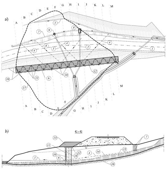
Figure 3.
Landslide and buttress constructed as an SSC: (a) layout plan showing the landslide outline with drain system and the SSC; (b) the cross-section of G-G across the landslide and SSC; 1—Existing culvert for water from drain trench; 2—Existing culvert for water from the central part of landslide; 3—Designed steel culvert pressed along the rock ceiling; 4—Drain pipes dewatering the landslide mass; 5—Drain pipe catching water from the slope; 6—Drain pipes draining water from under the buttress; 7—Designed drain pipes dewatering gravel in the sheet piles; 8—Existing collective chamber for leaking water; 9—Collecting well for leaking and surface water; 10—SSC wall from steel sheet piles; 11- SSC drilled piles supporting load force of buttress; 12—SSC reinforced concrete wale slab; 13—SSC ballast in the form of a soil bank; 14—Slide surface of the landslide; 15—Rock alluvium; 16—Rock; 17—Edge of landslide; A-A to M-M cross-sections, in which stability conditions of the whole slope and the buttress were analysed; 18—Vertical column-gravel drains in the geotextile sleeve inserted previously into the drained space.
The main sign of mass movement was the subsidence of the road grade line observed over many years. The road was levelled by adding small layers of the surface over decades. The total thickness of these layers reached 1.2 m. This vertical movement was the most burdensome and was monitored before and after the enhancement by SSC. In a short time, the results of observations indicated the undisputed effectiveness of the applied SSC reinforcements. Obviously, it could not be a fully satisfactory result due to theconditions in whichthe monitoring took place. The question is whether the weather conditions were unfavourable and whether the observation period was long enough. Therefore, despite the excellent initial results, it was decided to reevaluate the effectiveness of this support many years after building SSC. The supported slope has been stable for 21 years and has endured a period of heavy rainfall, especially in 2010. Thus, we can now consider that the method of using SSC was effective under conditions experienced in 1999–2020, due to the cessation of vertical movements of axel of road.
The landslide (Figure 3) was located on a relatively steep mountain slope, at the base of which in the valley flows a stream gathering rainfall water and spring water outflows from small gullies shaped in the slope. One such gullywas crossed by an embankment with a road on it. The rainwater from the slope drained under the road via a concrete culvert with a diameter of 125 cm. The culvert was not located in the syncline, but on its edge due to construction difficulties and waterlogging. This fact along with adverse features in the clay layer of soil base triggered the landslide causing deformation of the road. In order to stabilise the reactivated landslide, it was necessary to construct an auxiliary buttress due to unfavorable factors thatoccurred near the road bank.
In the case presented in this section, landslide stabilisation required:
- −
- increasing the strength parameters of the plasticised base soil,
- −
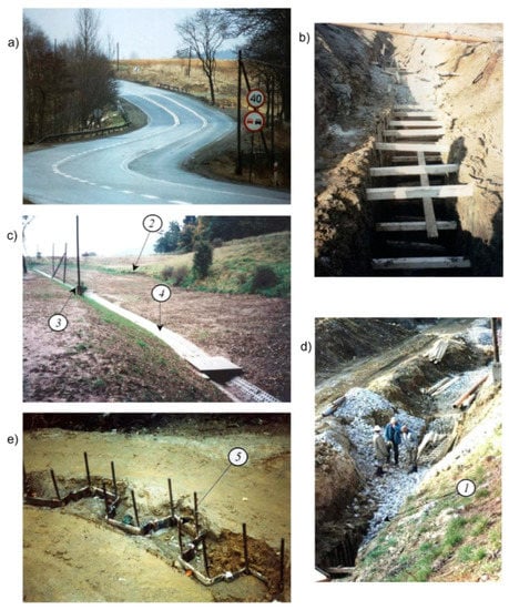 Figure 4. Views of SSC and draining elements (from Figure 1 and Figure 3): (a) View from road of visible landslide range (darker surface); (b) trench for drainpipe installation (item 1); (c) section of landslide after completion of works; (d) drain formed from pebbles; (e) Top of sheet piles after placement to the soil (before uncovering on depth about 20 cm and making the column-gravel vertical drains in the geotextile sleeve); 1—Main drain pipe; 2—Outline of upper edge of landslide; 3—Inlet of main dewatering interceptor; 4—Surface water intake; 5—Preparation of sheet piles for connection with wale slab.
Improvement of base soil parameters (c and ϕ) was accomplished by preventing the infiltration of rainwater and facilitating groundwater flow away from the base and towards the natural watercourse. Meanwhile, the buttress was constructed in the form of a relevantly-shaped SSC (Figure 3), mobilising the forces that counteract the sliding movement.
The problem of accumulation of groundwater was analyzed in the presented case and was an important element of the stabilization of the landslide mass. In the analysis of hydrological conditions, it was found that the groundwater and rainwater from the zone above the landslide body would be discharged through a special three-stage drainage system. The first stage of the drainage system (Figure 3 (7)) was localized on the top of the landslide. This made it possible to eliminate the water supply to the landslide from outside. However, the body of the landslide collects rainwater itself from its surface and this water penetrates inside creating a changeable level of groundwater in the landslide body. Therefore, a system of steel pressed drains was applied, through the opening in the SSC in the form of needle-filters located on the top of the slip layer, which is an impermeable layer (Figure 3 (4)). The role of this system is to discharge water from the landslide body downwards beyond the slope to the river. The third stage water drainage system was located in the recesses of the buttress in which water collects. Due to the shape of the buttress, the water flow is direct to these recesses. Moreover, the vertical column-gravel drains (Figure 3 (18)) are localized in these cavities, which discharge water outside. The water from these dewatering systems is drained through perforated pipes placed inside the drains (column-gravel filters), crossing the SSC to the water drainage system and to the river.
The closed three-stage dewatering system eliminates the risk of a high level of water formation in the landside body under normal weather conditions. However, in order to ensure stability in catastrophic conditions for heavy rainfall of high intensity, the possibility of the water pressure in the slope on the maximum predicted level was taken into account. This water pressure was taken into account in the stability analysis of the slope and the SSC.
The landslide dome constituted a thick layer of liquefied base soil (4–10 m) moving with the road bank on the loamy rock slope composed of mica schist. The sliding layer formed on the mica schist. Due to this fact, the stabilising of the landslide dome required the application of a special SSC formed in the way shown in Figure 3 and Figure 4e. In addition, it was necessary to construct a drainpipe for dewatering (Figure 3a item 7 and Figure 4b,d) as well as a culvert (Figure 3a item 3) made by the pressure system. The common effects of dewatering the rock mass and securing the SSC stabilised the landslide mass on the road, which was not accomplished in the prior 60 years of its existence.
Monitoring of the road body (road grade line and shoulderAMSL (above mean sea level) and shape) was carried out by the investor and user of national roads. These measurements clearly show that the displacements observed earlier disappeared after the application of repair works and have not resumed until now. This state occurred despite periods of intensive rainfall (e.g., in 2010). The applied buttress and supporting dewatering system allowed for the stabilising of the recurring landslide, which validates the assumptions made in the presented method.
4.2. Stabilisation of Activated Landslide with the Simultaneous Widening of the Road, Example 2
The second example is a landslide formed on a mountain slope (Figure 5 and Figure 6). On the slope side, there was a closed depression with no outlet, which was periodically filled with water during rainfall.
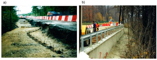
Figure 5.
Example of application of the SSC for stabilisation and widening of the road (Bardo Slaskie): (a) Making the sheet pile wall along the line in the shape of a wave created from semicircles; (b) A ready buttress.
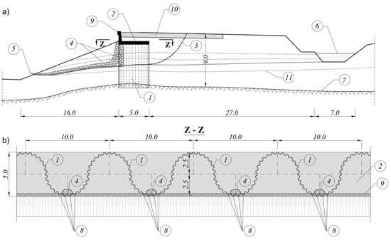
Figure 6.
The SSC stabilizing the landslide (also presented in Figure 5): (a) The cross-section across the landslide, road and spatial supporting construction; (b) The horizontal cross-section Z-Z across the buttress, 1—Tight steel wall from the sheet piles; 2—Reinforced concrete wale; 3—Slide surface of the landslide; 4—Drain pipes behind and in front of the tight wall; 5—End of the drain pipes; 6—Water collected in the trench; 7—Rock alluvium; 8—Holes in the sheet piles; 9—Retaining wall; 10—Road; 11—Soil layer margins. All dimensions are given in [m].
The embankment and construction of the road in this section were located on a layer of Holocene clay and dust with layers of sand. These soils filled up the depression in the slope forming a surface overlay on the soft Carboniferous shale rock. In these soil conditions, the landslide formed moved slowly with a substantial part of the road bank (Figure 6a). The principal causes of the landslide were:
- locating the road on soils susceptible to humidity changes and easily plasticised,
- incorrect surface and groundwater intake and drainage from water areas with no outlet, and
- steep and parallel inclination of soil layers and rock base.
The road section was subject to long-lasting (over 50 years) slow slippage. Displacements were slow during periods without precipitation and more rapid during periods of intensive rainfall. The sliding section of the road crown was successively repaired using asphalt concrete. Because a business (an inn) was located on the road near the landslide, it was necessary to widen the road by one traffic lane along the entire length of the landslide (Figure 5b). Due to this fact, it was considered necessary to construct the buttress (Figure 5 and Figure 6). SSC was supposed to stabilise the long-lasting active landslide and at the same time, widen the road in the vicinity. The magnitude of unbalanced pressure on the slump block wasdetermined according to Ukleja [24] following the principles presented above in Section 3.1. This pressure had to be balanced with the buttress shown in Figure 6.
In order to stabilise the landslide, it was necessary to build a buttress in the form of the SSC in the following way:
- to construct a massive reinforced wale slab, integrated with the sheet pile wall formed a rigid spatial supporting construction. Such a construction, even without reinforcement piles, is able to transfer horizontal forces exerted by the landslide mass, and
- ballasting the whole structure (over the wale slab level) with a load of stabilising soil in addition to a spatial supporting construction.
Calculations made for this case demonstrate that it is possible to give up installing the piles supporting the wall. In order to preserve SSC stability were enough the remaining elements in this case (steel sheet pile wall, slab, ballast, and control of rainwater outflow.
The presented examples of the application of the spatial buttress turned out to be the simple construction for building, effectively stabilising the landslide and widening the road as much as possible. Controlling the rainwater draining from the landslide also has an important meaning. Apart from eliminating faults from the existing solutions, the suggested SSC hasmany advantages, including:
- (a)
- easy execution (i.e., no need to dig trenches that in turn influence slope stability),
- (b)
- optimal utilisation of construction materials (especially of tight steel sheet pile wall) due to its relevant forming as a shape similar to a wave,
- (c)
- possibility of locating the buttress in a suitable place, not necessarily near the landslide forefront, and
- (d)
- possibility of utilising the soil ballast to increase the mass of the buttress, which does not increase the mass of the landslide slump block.
Meanwhile, the faults in the proposed solution, which have to be minimized, were due to:
- (a)
- need for dewatering system for the landslide mass to drain groundwater from createdbarrier the sheet pile walland,
- (b)
- applying the proposed buttress only in the case of landslides with small movement velocity, enabling people and equipment to work in the landslide area.
The attractiveness ofthe presented SSC depends on the ability to maximise the support of the landslide slump block by includingthe weight of the stabilised landslide soil and the weight of specially-formed embankments over the reinforced concrete wale slab co-working with the structure, which represents an addition to the supportby the SSC. The best effects can be accomplished on shallow landslides over the intact layer of the stable (strong) base layer, lying below the slide surface. The important circumstance, which supports this solution, is the inability to apply other typical solutions. This circumstance occurs when the forefront of the landslide undergoes intensive river erosion or when the types of rocks do not allow for the application of effective anchoring of the structure to the base.
5. Conclusions
The examples of SSC and assumptions presented in this study for its stability calculations allowed for applying this kind of unique structure in practice. It was demonstrated in the two examples presented for stabilising state road No. 8 in the area of Bardo Slaskie in south-east Poland. This solution enabled the control of recurring landslides with relatively little work and in a very efficient way.
Based on the results of the study SSC with respect to slope stability, and observations of the behaviour created in the full-scaleSSC, we can conclude:
- The applied way of forming the tight sheet pile wall along a wavy line causes the multiplication of its bending resistance, thus increasing its efficacy as a buttress from using this kind of material.
- The bottom part of the wall, which is shallowly embedded into the stable base (usually solid or rocky), attaches the whole SSCpreventing its movement. Still, it is not necessary to dig the wall deep into the bearing layer below its contact with the slide surface. Topping the wall with a reinforced concrete wale slab makes a strong joining element. This slab constitutes the connecting element joining all of the components of the SSC, thus uniting them as a whole.
- Ballast in the form of embankments or road surfaces on the reinforced concrete slab constitutes an additional element supporting equilibrium in the buttress. The soil mass plus slab can balance part of the pressure of the landslide mass on the SSC.
- Lightness of construction, along with ease and safety of execution, make this solution very attractive. The substantial feature of spatial supporting constructions is the possibility offitting the effects to specific landslide stabilization, which can be accomplished by changing:
- (a)
- curvature and shape of sheet pile wall,
- (b)
- diameter and depth of piles supporting the load capacity of the wall (or resignation of their application),
- (c)
- dimensions of the slab concrete and mass of its ballast.
- Taking the advantages of this solution into consideration, some assumptions were labored for SSC dimensioning with respect to all reactions, including the pressure of the slump block on the buttress. This allows for the construction of a buttress able to compensate for the forces occurring in the slump block, consequently stopping the active landslide.
- A very important issue in this solution is the installation of vertical drain pipes along the wall surface and draining of accumulated waterfrom the pipes on the other side of the buttress. This is necessary because, without these drains, the tight buttress may act as a barrier to water flow through the soil.
Funding
This research received no external funding.
Conflicts of Interest
The author declare no conflict of interest.
References
- Gunther, A.; Reichenbach, P.; Malet, J.-P.; Vanden Eeckhaut, M.; Hervas, J.; Dashwood, C.; Guzzetti, F. Tier-based approaches for landslide susceptibility assessment in Europe. Landslides 2013, 10, 529–546. [Google Scholar] [CrossRef]
- Akin, M. Slope Stability Problemsand Back Analysisin Heavily Jointed Rock Mass: A Case Study from Manisa, Turkey. Rock Mech. Rock Eng. 2013, 46, 359–371. [Google Scholar] [CrossRef]
- Day, R.W. Reactivation of an Ancient Landslide. J. Perform. Constr. Facil. 1995, 9, 49–56. [Google Scholar] [CrossRef]
- Beben, D.; Anigacz, W.; Ukleja, J. Diagnosis of bedrock course and retaining wall using GPR. Elsevier NDT E Int. 2013, 59, 77–85. [Google Scholar] [CrossRef]
- Ukleja, J.; Beben, D.; Anigacz, W. Determination of the railway retaining wall dimensions and its foundation in difficult terrain and utility. J. Min. Geoengin. 2012, 36, 299–308. [Google Scholar]
- Gasmo, J.M.; Rahardjo, H.; Leong, E.C. Infiltration effects on stability of a residual soil slope. Comput. Geotech. 2000, 26, 145–165. [Google Scholar] [CrossRef]
- Villemus, B.; Morel, J.C.; Boutin, C. Experimental assessment of dry stone retaining wall stability on a rigid foundation. Eng. Struct. 2007, 29, 2124–2132. [Google Scholar] [CrossRef]
- Katzenbach, R.; Leppla, S.; Ramm, H.; Seip, M.; Kuttig, H. Design and construction of deep foundation systems and retaining structures in urban areas in difficult soil and groundwater conditions. In Proceedings of the Procedia Engineering, 11th International Conference on Modern Building Materials, Structures and Techniques, MBMST, Vilnius, Lithuania, 16–17 May 2013; Volume 57, pp. 540–548. [Google Scholar]
- Salcedo, D.A. Behavior of a landslide prior to inducing a viaduct failure, Caracas–La Guaira highway, Venezuela. Eng. Geol. 2009, 109, 16–30. [Google Scholar] [CrossRef]
- Cruden, D.M.; Varnes, D.J. Landslide Types and Processes. Special Report Transportation Research Board. Proc. Natl. Acad. Sci. USA 1996, 247, 36–75. [Google Scholar]
- Varnes, D.J. Landslide Typesand Processes. In Landslides and Engineering Practice; Eckel, E.B., Ed.; HRB; National Research Council: Washington, DC, USA, 1958; Volume 29, pp. 20–47. [Google Scholar]
- Hungr, O.; Leroueil, S.; Picarelli, L. The Varnes classification of landslide types, an update. Landslides 2014, 11, 167–194. [Google Scholar] [CrossRef]
- Brencich, A. Deep trench, landslide and effects on the foundations of a residential building: A case study. Eng. Struct. 2010, 32, 1821–1829. [Google Scholar] [CrossRef]
- Azm, S.A.; Ahmad, B.T.; Salah, T. A comparative study of slope stability methods and mitigative design of a highway embankment landslide with a potential for deep seated sliding. Eng. Geol. 1997, 47, 157–173. [Google Scholar]
- Beben, D. Corrugated steel plate culvert response to service train loads. J. Perform. Constr. Facil. 2014, 28, 376–390. [Google Scholar] [CrossRef]
- Liao, S.; Li, W.; Fan, Y.; Sun, X.; Shi, Z. Model test on lateral loading performance of secant pile walls. J. Perform. Constr. Facil. 2014, 28, 391–401. [Google Scholar] [CrossRef]
- Farzaneh, O.; Askari, F.; Fatemi, J. Active earth pressure induced by strip loads on a backfill. Int. J. Civ. Eng. 2014, 12, 281–291. [Google Scholar]
- Hajiazizi, M.; Mazaheri, A.R. Use of line segments slip surface for optimized design of piles in stabilization of the earth slopes. Int. J. Civ. Eng. 2015, 13, 14–27. [Google Scholar]
- Polish Standard. PN-83-B-03010. Retaining walls. Static Calculation and Design; Polish Committee for Standardization: Warsaw, Poland, 1983.
- British Standard. BS 6349 1, Code of Practice for Maritime Structures Part 2: Quay Walls and Dolphins; British Standards Institution: Chiswick, UK, 1988. [Google Scholar]
- Labuz, J.F.; Zang, A. Mohr–Coulomb Failure Criterion. Rock Mech. Rock Eng. 2012, 45, 975–979. [Google Scholar] [CrossRef]
- Wilun, Z. Outline of the Geotechnics; Wydawnictwo Komunikacjii Lacznosci: Warsaw, Poland, 1982; pp. 175–180. [Google Scholar]
- Ukleja, J. Calculation of range of slides of structural type on haulage benches in surface mines. Gor. Odkryw. 1996, 1, 56–70. [Google Scholar]
- Ukleja, J. Stability estimation of slope shaving their slip surface determined by means of the STAB-3D method based on sliding body equilibrium analysis. Geol. Q. 2016, 60, 597–609. [Google Scholar] [CrossRef][Green Version]
- Ukleja, K.; Ukleja, J.; Tatarczyk, B. Stabilisation of a Road Body Shapedina Slope Failure. In XIIth European Conference on Soil Mechanics and Geotechnical Engineering; Geotechnical Engineering for Transportation Infrastructure: Amsterdam, The Netherlands, 1999; Volume 2, pp. 1391–1397. [Google Scholar]
- Polish Standard. PN-83/B-02482, Foundations. Bearing Capacity of Piles and Pile Foundations; Polish Committee for Standardization: Warsaw, Poland, 1983.
- Ukleja, K.; Ukleja, J. Structural landslide supporting by construction of a steel assisting buttress. In Proceedings of the P. N. I. G. H. Wroclaw University of Technology, XXIV Z.S.M.G. Conferences, Ladek Zdroj, Poland, 12–16 March 2001; Volume 73, pp. 12–16. [Google Scholar]
- Ukleja, K.; Ukleja, J. The stabilization of road body formed inland slips. Gor. Odkryw. 1999, 4–5, 149–157. [Google Scholar]
Publisher’s Note: MDPI stays neutral with regard to jurisdictional claims in published maps and institutional affiliations. |
© 2020 by the author. Licensee MDPI, Basel, Switzerland. This article is an open access article distributed under the terms and conditions of the Creative Commons Attribution (CC BY) license (http://creativecommons.org/licenses/by/4.0/).