1. Introduction
Cold gas thrusters have been used in the space industry since the 1960s. They are preferred for all ranges of orbits and inter-planetary missions [
1]. The main reasons for their popularity are the cost effectiveness, environmentally friendly characteristics and highly reliable systems.
Due to their simple structures and use of propellants, which produce no contamination, it is easier to construct laboratory level cold gas thruster test setups [
2]. In addition to that, other types of thruster systems also use similar pneumatic valves. Although there are differences in terms of dynamical characteristics between the cold gas types and other types of thruster systems, control strategies applied to the cold gas thrusters can also be applied to any kind of thruster system with some modifications.
The inverted pendulum system is a classical control problem application that has been used for decades. The system, whether it is rotary or linear, has inherently unstable, under-actuated and nonlinear dynamical characteristics. Due to these dynamical characteristics, many researchers employed their newly proposed control schemes on the inverted pendulums.
In the literature, there are different types of inverted pendulums using various type of actuators. The most classical one is an electric motor directly controlling the rod or the cart position. Hydraulic and pneumatic cylinder actuated pendulums are also widely used [
3]. In addition to those, there are inverted pendulum systems controlled by reaction control systems. Many applications use reaction masses and control moment gyroscopes as an actuator for the inverted pendulum system [
4]. Reaction masses and control moment gyroscopes are commonly used for spacecraft attitude control applications.
In this work, another type of reaction control system, the cold gas thruster, is used as an actuator for the rotary inverted pendulum system. Cold gas thrusters have not been used as an actuator for the inverted pendulum systems before. The main difference and challenge when compared with other types of actuators is that the cold gas thruster system used in this work is an on–off type of actuator. Thus, this work extends the difficulties of the inverted pendulum system by adding on–off characteristics on the actuator.
To summarize, the motivation of this work stands on two pillars.
Inverted pendulums have not been actuated by on–off-type thrusters before in the literature. This is the first study employing such actuators with the conventional control approach for rotary inverted pendulums. Nonlinearity of the system becomes higher compared to the other types of actuators.
The system has high similarities with the thruster actuated spacecrafts having slosh dynamics. The approach used in this study can improve spacecraft control.
The rest of the article is organized as follows. The next section discusses the related background, and the dynamics of the inverted pendulum are summarized in
Section 3. Controllers for swing-up and stabilization of the pendulum are introduced in
Section 4. Then in
Section 5, the performance of the controller is evaluated on the rotary inverted pendulum system. The paper is concluded with critical remarks and discussions of future works in
Section 5.
2. Background
Related literature is elaborated under two main topics; cold gas thrusters and inverted pendulum control.
2.1. Cold Gas Thrusters
In some spacecraft applications it is not possible to use aerodynamic control surfaces. Since aerodynamic force is proportional to the medium density and the relative velocity between the fin and the medium, performances of control actuation fins are not sufficient at high altitude atmosphere, out of atmosphere and at low velocity applications. In addition to these conditions, high maneuverability is not possible with the fin actuator due to the separation limits of the fin. For this case, reaction control systems are used for control applications. One of the most used reaction control systems are thrusters. Cold, warm and hot gas thrusters are the types of thrusters based on the output temperature of the expelled gases. For thruster actuated systems, generally on–off type of valves are used because of their simpler structures. There are few moving elements inside and they are highly cheap compared to the servo/proportional valves.
Most used control techniques for on–off type of actuators are bang-bang and pulse modulators. Bang-bang control requires nonlinear analysis. By using pulse modulators, a quasi-linear output can be obtained from an on–off actuator and linear control techniques can be applied. Pulse Width Modulation (PWM) is the most common pulse modulation technique. Many works presented in the literature are related to the study are about PWM design for thrust control applications [
5,
6,
7,
8,
9,
10,
11]. Furthermore, there are studies on duty cycle limits affecting the performance of thruster valves. In a related study, Suzuki et al. [
12] focused on the minimum pulse-width that can be achieved by the on–off valves. They improved the performance of the controller using the results obtained in the experiments. Jeon et al. [
13] performed several experiments on the thrust output to determine the opening and closing characteristics of the thrusters. After these systematic experiments, they used the results to obtain the limit cycle characteristics in their setup. In a similar study, Bals and Kienitz [
14] utilized the valve opening and closing times to determine the maximum switching frequencies for their modulation approach.
There are several studies on PWM design and the restrictions on the switching of on–off valves in literature. For instance, Taghizadeh et al. [
15] proposed a simplification approach for PWM control applications. They derived a static model between the spool position and the duty cycle input. In another study, Topcu et al. [
16] studied electrically operated pneumatic fast-switching valve, which can be used for the position control of pneumatic systems. After investigating the characteristics of the valve, they used the results for the design of PWM.
2.2. Inverted Pendulum Control
An inverted pendulum system is an inherently unstable, nonlinear, non-minimum phase and under-actuated control problem that has been widely used for decades as an experimental test setup to demonstrate and verify different kinds of control schemes. Swing-up, balancing, switching and trajectory control are the main tasks for the inverted pendulum test setups. The inverted pendulum problem can be considered as an example for thrust vectoring during vertical launch, vertical take off and landing (VTOL) of aircraft, control of a robotic arm and humanoid robots.
Matsumoto [
17] used the analogy of the inverted pendulum problem for the hovering strategy of VTOL unmanned aerial vehicles (UAVs). The inverted pendulum phenomenon is also utilized commonly to stabilize the unstable fuel slosh of a spacecraft with sloshable fuel. The traditional way of minimizing the fuel slosh is to add baffles to the fuel tank. However, this method increases the weight of the spacecraft and adds structural complexity to it [
18]. There are many works in the literature that use a fuel slosh sensor and controller to overcome the slosh problem of spacecrafts [
19,
20,
21,
22,
23]. In this way, the necessity of baffles disappears. Slosh dynamics are generally modeled as a pendulum or a mass-spring-damper system. When slosh dynamics are modeled as a pendulum, the problem becomes the same with the stabilization of an inverted pendulum and rod tracking. The slosh control problem is also underactuated and unstable.
The most common type of inverted pendulum is the cartesian type. In this type, moving mass is actuated by a linear force and the pendulum is attached to the mass by a revolute joint. Different types of controllers are proposed for the control of cartesian type inverted pendulums. Kumar [
24] proposed a linear quadratic regulator for balancing the motion. Chen [
25] used sliding-mode control with fuzzy modeling for the same goal. Wai [
26] proposed adaptive sliding-mode control for a dual-axis cartesian inverted pendulum. El-Hawwary [
27] proposed an adaptive fuzzy control for the stabilization.
A rotary inverted pendulum test setup was first introduced by Furuta [
28] in 1991. It is a system composed of a rotating pendulum attached to a rotating arm by a revolute joint. Compared to the conventional pendulum on a cart system, it requires less space and fewer unmodeled dynamics since all of the joints are revolute joints. In addition to that, the rotating arm can rotate infinitely by using proper sensor wirings. Infinite rotation provides convenience and a large area for trajectory control during the experimentation.
Throughout the years, many different controller types have been proposed and tested for rotary inverted pendulum test setups. Furata first [
28] used a bang-bang type of state feedback algorithm for the swing-up controller and optimal quadratic regulator for the balancing controller. Yang [
29] proposed trajectory planning for the swing-up motion and an adaptive neural network controller for the stabilization. Sainzaya [
30] reported experimental results of the Linear Quadratic Regulator with a refined PID controller for balancing the motion.
Another type of inverted pendulum is the reaction mass pendulum (RMP). It is a pendulum link attached to the ground by a revolute joint and the rotating controllable mass is attached to the pendulum. The reaction mass control is based on the conservation of momentum and this phenomenon is generally used for attitude control of spacecrafts. Andrievsky [
18] used an energy based speed gradient control scheme for the swing-up motion and variable structural control for the stabilization of the RMP. Spong [
31] experimentally compared feedback linearization and pole placement methods. The work resulted that feedback linearization and approximate linearization with pole placement methods are comparable. Scalera et al. [
32] used feedback linearization control and online trajectory planning based on adaptive frequency oscillators for three-degrees-of-freedom an underactuated pendulum-like cable driven robot. In another study, Garcia-Sanchez et al. [
33] implemented a hierarchical controller approach to a differential drive wheeled mobile robot, which is an underactuated and non-holonomic system. Martinez et al. [
34] handled actuator nonlinearities by a regulator containing the sigmoid mapping.
There are experimental cartesian inverted pendulum setups driven by pneumatic or hydraulic cylinders [
3,
35,
36,
37]. Compared with the electrically driven ones, although similar control strategies can be applied, differences emerging from the pneumatic or hydraulic characteristics should also be considered and modeled for these types.
3. Dynamics of the Rotary Inverted Pendulum
In this section, the equation of motion is obtained by constructing the dynamical model of the rotary inverted pendulum. The Lagrangian method is used to model the rotary inverted pendulum dynamics.
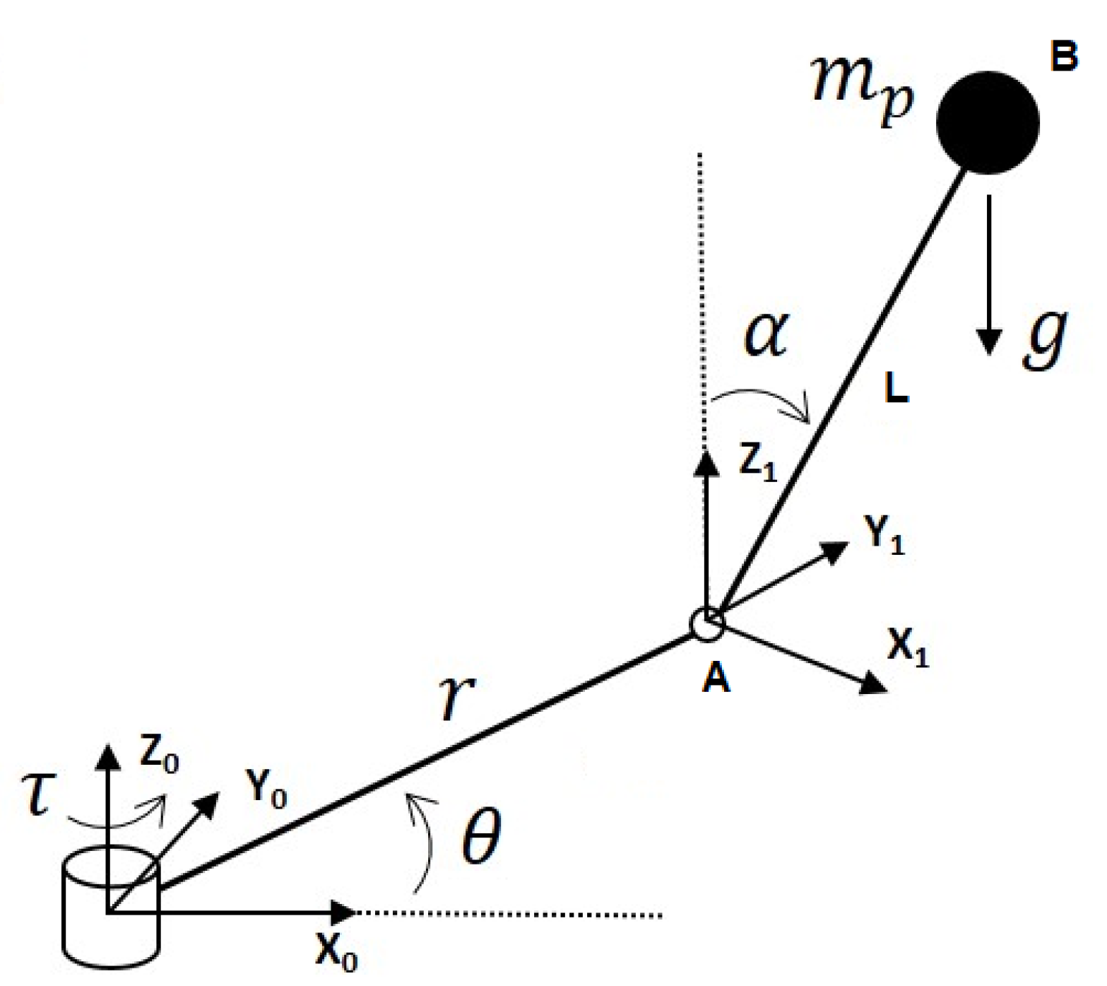
Figure 1 shows the free body diagram of the rotary inverted pendulum. In this schematic,
is defined as the rod angle and
is the pendulum angle. Although the system is spatial, it can be separated as two planar systems. Since centrifugal forces are not effective on the control action of the system, they are not considered on the free body diagram and are not going to be taken into consideration. Using the free body diagram, the kinematic equations for point A can be written as
Kinematic equations for point B with respect to the point A are
According to the relative motion principle
Mass moment of inertia of the rod about mass center of the rod is
Mass moment of inertia of the pendulum about the mass center of the pendulum is
Total potential energy is
Then, the Lagrangian function is written as
In the above equation, the Q term is the input and for the particular system it is the thrust force.
For stabilization, linear control methods are applied. Nonlinearity originated from the inverted pendulum kinematics is assumed as linear around the up-right position of the pendulum. Since the balancing controller is on around the up-right position, it is a valid assumption of the application. The designed linear controller and linear assumption are validated on the nonlinear model in
Section 4.4. The linearized version of Equation (
16) is
The linearized version of Equation (
17) is
Parameters related to Equations (
18) and (
19) are given in
Table 1.
Since the balancing controller is used near the equilibrium position, the peak torque is required around the equilibrium position. The limit is determined as 10 degrees from the upper equilibrium position. The required torque to balance the pendulum is calculated as below.
Required acceleration at the point A is
The required thruster torque is lower than the maximum thrust torque (1.25 Nm) of the actuator as given below.
4. Controller Design
In this section, the design of the inverted pendulum controller is presented. Due to the nonlinearity of the pendulum motion, pendulum dynamics are linearized around the upper equilibrium point. Thus, the pendulum motion is divided into two phases. One is the swing-up motion and the other is the balancing motion. In this way, the balancing motion is accomplished using a linear controller. If the angle of the pendulum is smaller than 10 degrees, a balancing controller is used. For angles higher than 10 degrees, a swing-up controller is activated. The transition between the controllers is realized by a switch. Since the conventional methodology for the control of inverted pendulums is followed in this study, the complexity of the controller is highly similar to the ones in the literature [
29].
In the rest of this section, swing-up, balancing and switch controllers are presented.
4.1. Swing-Up Controller
A swing-up controller is used to overcome the nonlinearity of the system. Since the system is linearized near the equilibrium position, swing-up tries to bring the system near the equilibrium position. The energy control method is used for the swing-up action. This method calculates kinetic and potential energies of the pendulum. By knowing the total energy at the equilibrium position, the algorithm applies the necessary torque to the system [
38]. The total energy of the pendulum system at any instant of the motion is
The derivative of the energy equation is
Multiplying the equation of motion with the velocity of the pendulum and obtaining the energy change as
Using the above equation, the energy of the pendulum can be controlled simply by changing the acceleration of the rod. This can be accomplished by applying the necessary torque on the rod.
Controllability is lost when the coefficient of acceleration vanishes. This occurs when
is zero or
is 180 degrees. To increase energy, the acceleration of the rod should be positive when the quantity
is negative. Then, the required acceleration of the rod can be found as below [
38].
The above equation can be utilized to adjust the required acceleration using real time energy as the feedback value. When the total energy approaches the equilibrium energy, it lowers the acceleration. An appropriate gain value should be selected for this system. is related to the torque limit and the time allowing for the swing-up motion.
4.2. Balancing Controller
The state feedback controller is employed as the balancing controller. It is designed after the state space model is obtained. Later, the state observer is designed to observe some non-measurable states. Details of the design are elaborated in the following subsections.
4.2.1. State Space Model of the Rotary Inverted Pendulum
In this part, the state space model of the inverted pendulum is constructed. Equations (
18) and (
19) are formed as below, respectively.
where
The states are rod position, rod velocity, pendulum position and pendulum velocity. The state space form of the equation of motion is
When numerical values are utilized, the below matrices are obtained.
A controllability matrix is constructed and it is shown that it is a full rank matrix.
4.2.2. State Space Model and Controllability in Discrete Domain
In this part, due to the nature of the PW modulated actuator, a discrete model is constructed and its controllability is examined.
The discrete model is constructed from a continuous time state space form.
where
Firstly, the state space equation is converted to discrete domain for 2 Hz PWM frequency. For this case, the state and the controllability matrices are given in Equations (
45)–(
47). Since the matrix is not a full rank matrix, the system is not controllable for the selected sampling period.
The minimum PWM frequency to ensure the controllability is calculated as 6 Hz by checking the rank of the controllability matrix. Considering the valve opening and closing dynamics, the PWM frequency is set to 20 Hz for better controllability. Later, the discrete domain state space form is constructed. For the selected frequency, the controllability matrix is full rank. It is observed that as PWM frequency is lowered, controllability is lost.
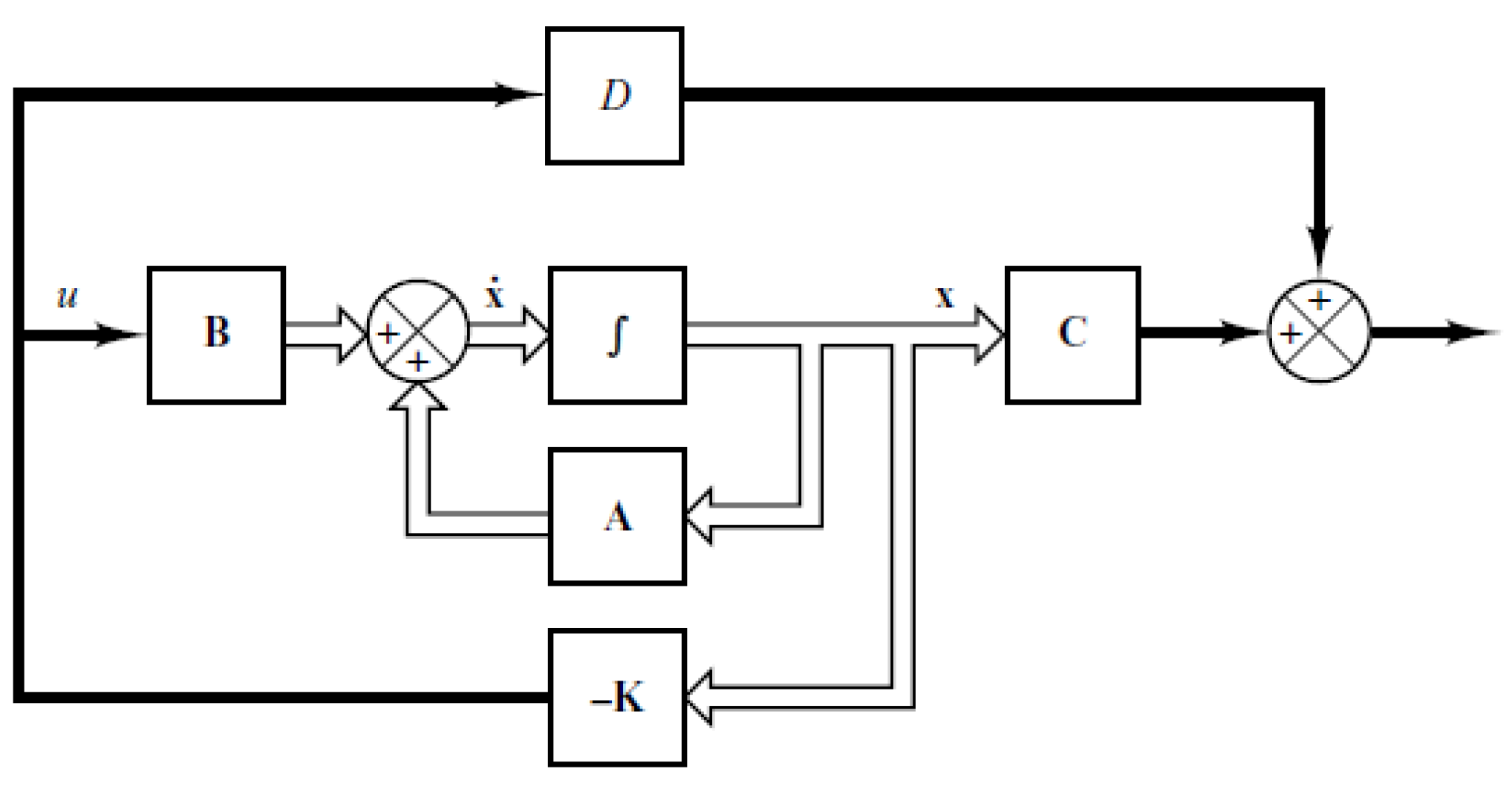
4.2.3. Full State Feedback Controller
In this part, a linear control method, full state feedback controller is designed. Controller gains are calculated for this commonly used control method. All states are assumed as measurable.
A block diagram of the full state feedback controller is given in
Figure 2. In this figure,
K is the state feedback gain matrix. The mathematical expression of the overall closed loop system is
The term in the parenthesis in the above equation determines the characteristics of the closed loop system. The eigenvalues of this term must be equal to the desired pole locations. Calculation of the
K matrix to satisfy the requirements of the eigenvalues is done by Ackermann’s formula, which is given in Equations (
49) and (
50).
(
A) is given below. In the below equation
,
,
and
are the coefficients of the desired characteristic equations.
Coefficients of the desired characteristic equations are tuned by selecting the desired pole locations for stability [
39] without saturated controller outputs. The highest possible system bandwidth is selected as
. The damping ratio is selected as 1 for no overshoot. Poles of the characteristic equations are calculated using the below equations.
For the discrete case, eigenvalues are converted using
A state feedback gain matrix is calculated according to Equation (
49) and given in Equation (
54).
4.3. Switching Controller
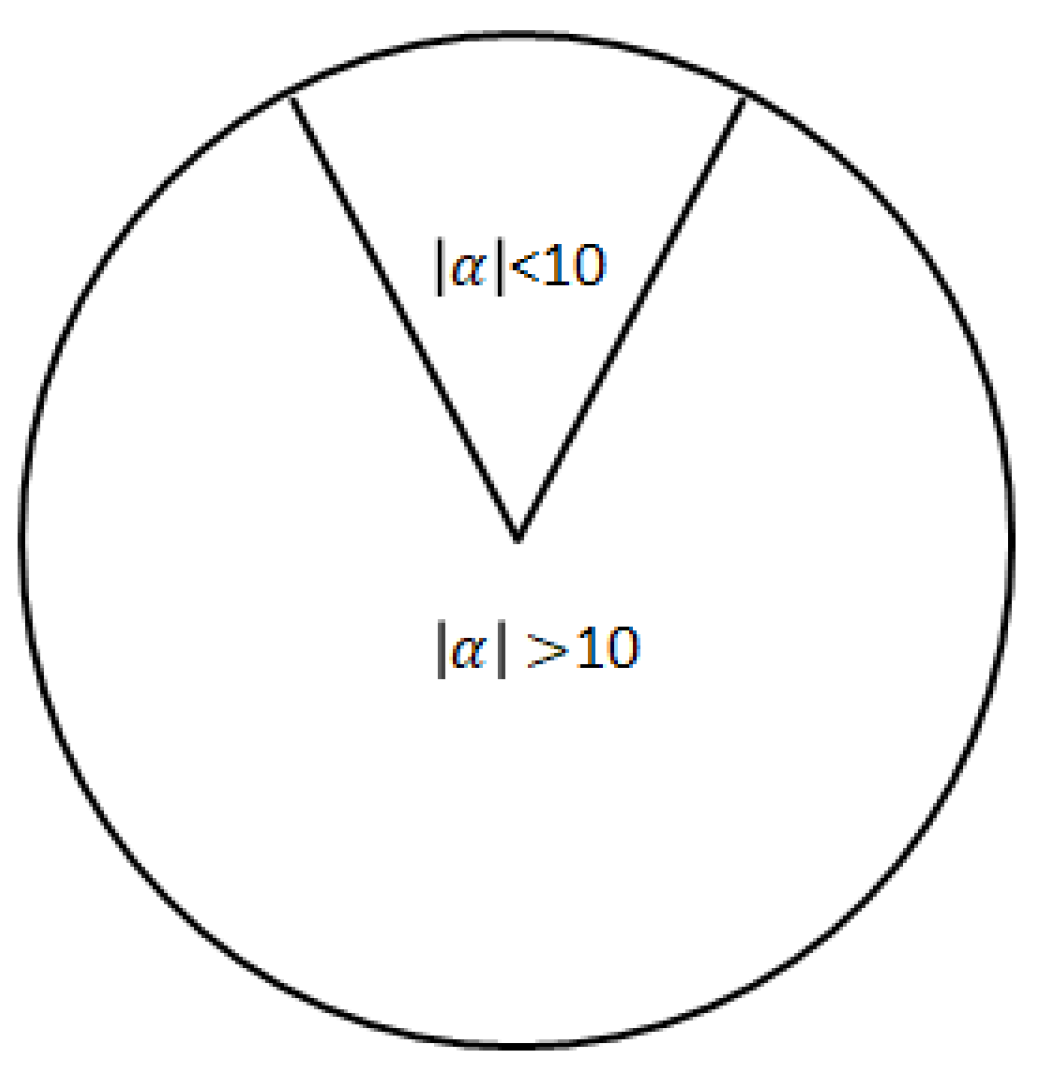
The switching controller switches the controller scheme between the swing-up and the balancing controllers. It decides which controller is to be used according to the angular position of the pendulum.
Figure 3 shows the phases of the controllers. When the absolute value of the pendulum angle (
) is smaller than 10 degrees, the balancing controller is used as stated in Equation (
55). For the remaining range, the swing controller is active. The transition between the controller phases is provided by a switch controller.
4.4. Simulation Results
To be able to observe the swing-up motion and the effects of the nonlinearities, the nonlinear inverted pendulum model is constructed in Matlab-Simulink. Simulations are done with different PWM frequencies and controller gains.
The angular position simulation was run for 10 Hz PWM frequency and discrete analysis. The controller was unable to catch and balance the inverted pendulum at the upright position. Another simulation was run with 20 Hz PWM frequency and continuous analysis. This controller was also unable to catch and balance the inverted pendulum at the upright position.
Figure 4 shows the angular position of the pendulum for 20 Hz PWM frequency and gains calculated by the discrete controller. According to the figure, it takes about eight seconds to swing up the pendulum to the up-right position. The simulation result is satisfying with discrete analysis and high frequency PWM.
Figure 5 shows thrust output, the control input during the inverted pendulum simulation.
5. Results of the Experiments
In this section, the details of the experimental test setup are first presented. Then, the results of the single axis and the inverted pendulum experiments are discussed. Discrepancies between the simulation and the experimentation results are elaborated.
5.1. Experimental Test Setup
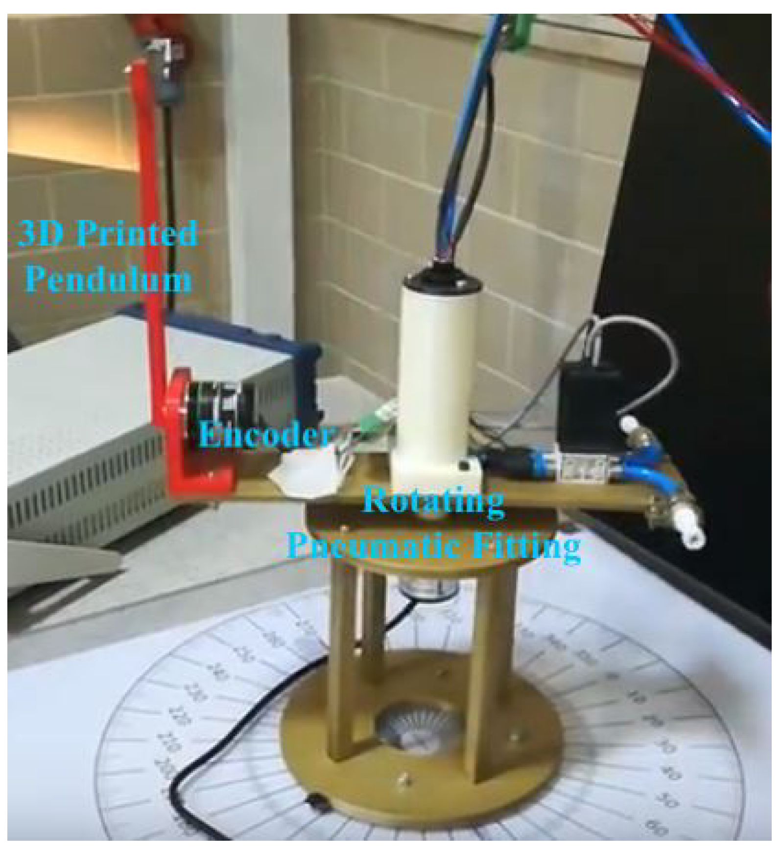
For the single axis and the inverted pendulum test setups, almost the same components were used. The only difference was a rotary encoder mounted on the single axis platform for the inverted pendulum. The pendulum was directly attached to the rotary encoder. Test setup parts can be separated as the parts related to structural, pneumatic, data acquisition and control duties. These parts are listed in
Table 2.
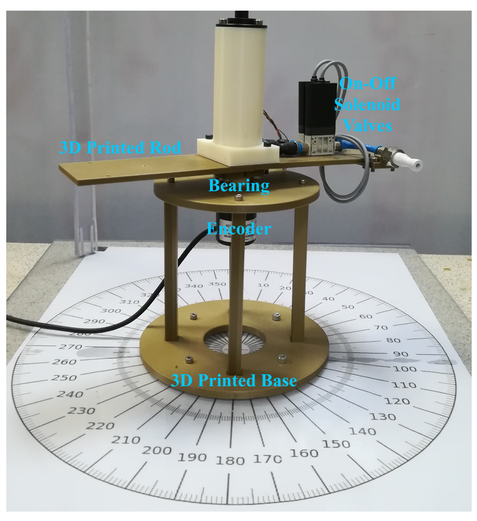
The structural part of the test setup was composed of a base part and a rod attached to the base part via a bearing. The base part, rod and other mechanical parts were manufactured using a 3D printer. The bearing provides unlimited and low frictional rotational motion.
The pneumatic part of the test setup was composed of a pressure regulator, two on–off solenoid valves, pipes and a rotating pneumatic fitting. Pressured gas was provided to the pressure regulator. The pressure regulator ensures constant pressure for the valves. It was placed at the outside of the test setup, but the valves were placed on the rotating platform. The valves operated without considerable delays. A low friction rotating pneumatic fitting was used to provide air supply from the regulator to the valves without preventing the rotational motion.
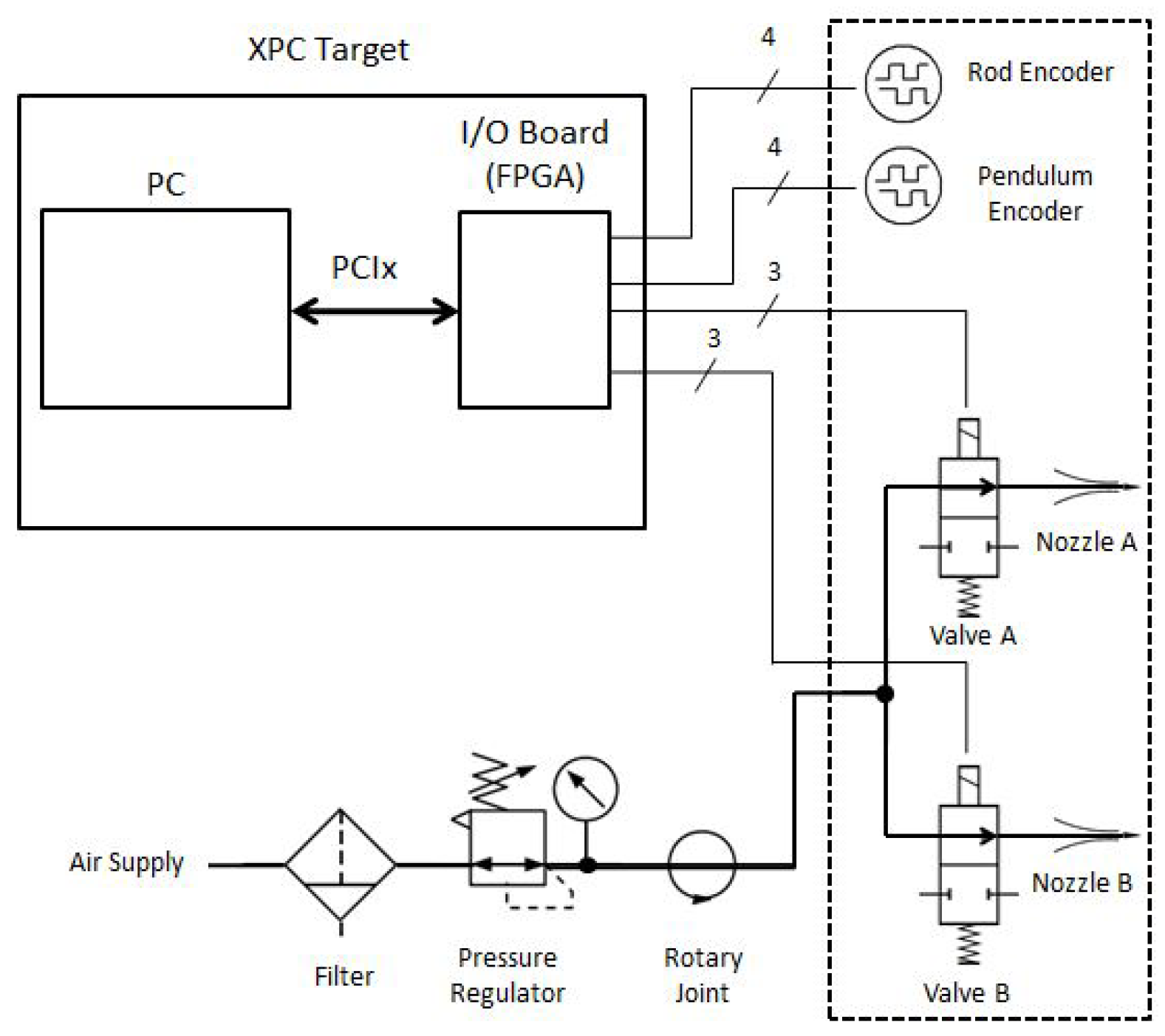
The data acquisition, control and signal/power routing part of the test setup were composed of a real time target machine, two incremental rotary type encoders, a slip ring and DC power supply. Inputs and outputs were interfaced via an FPGA-based board on the real-time target machine due to its availability in the lab. The target machine was run at 1 kHz frequency, which is much faster than the frequency of the PWM (20 Hz). Rotary encoders are the sensors of the control loop and they measure the rotational positions of the rod and the pendulum. The real time target machine takes encoder data, processes and generates control commands for the valves. Signals and power were delivered to the valve and the encoders using a rotational slip ring. In the test setup, unlimited and low frictional rotational motion was achieved by using the pneumatic rotating joint and the slip ring.
Figure 6 and
Figure 7 are photographs of the single axis and the rotary inverted pendulum test setups, respectively.
Figure 8 shows the general block diagram of the test setup.
5.2. Single Axis Experiment Results
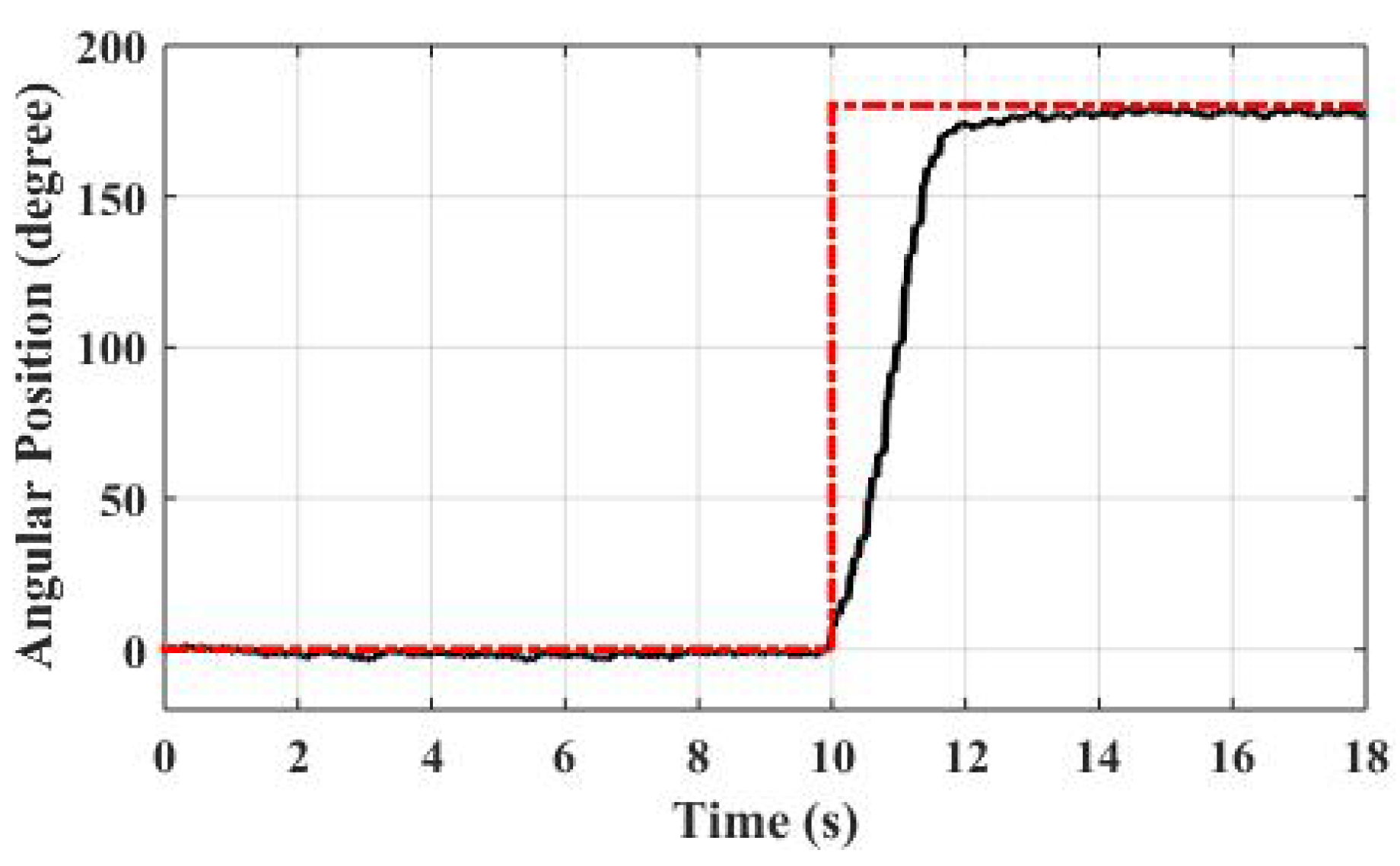
Figure 9 shows the angular position of the rotational platform during the single axis motion. For this particular experiment, a 180 degree angle command was applied to the system. According to the results, it takes two seconds for the closed loop system to reach the reference position. The system does not have any overshoot and the RMS value of the steady state error is 2.4 degrees.
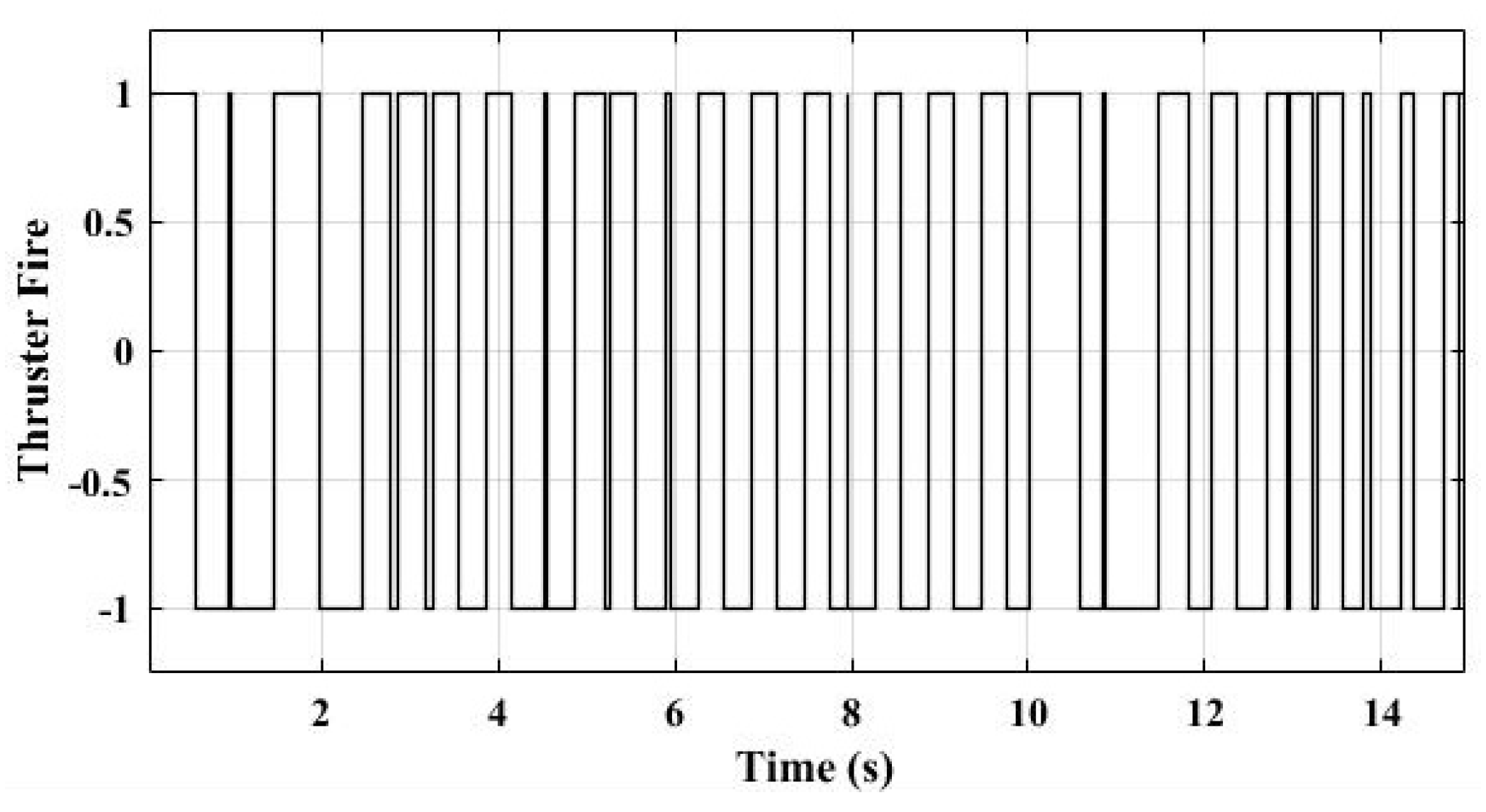
Figure 10 shows the thruster output during the single axis motion.
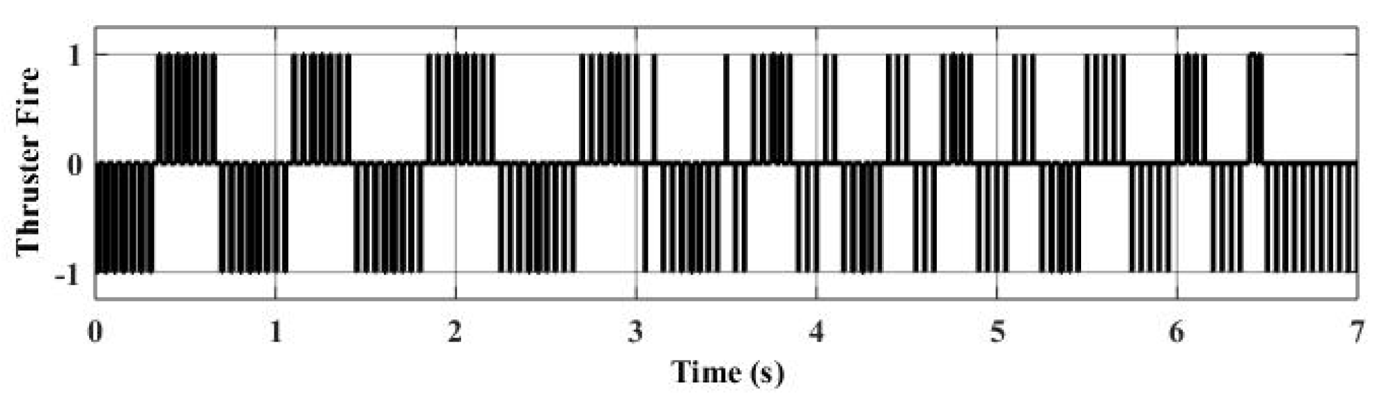
5.3. Inverted Pendulum Experiment Results
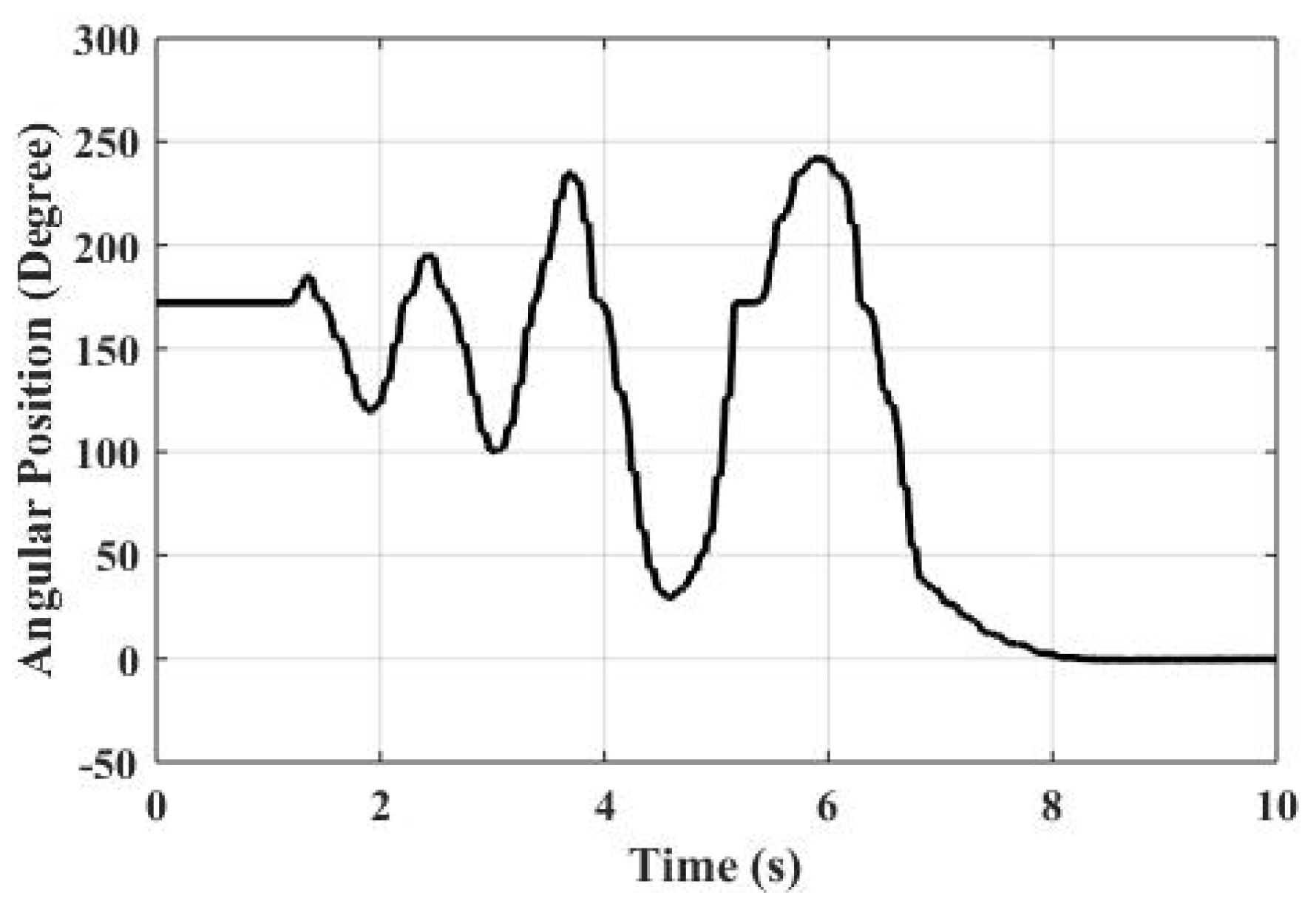
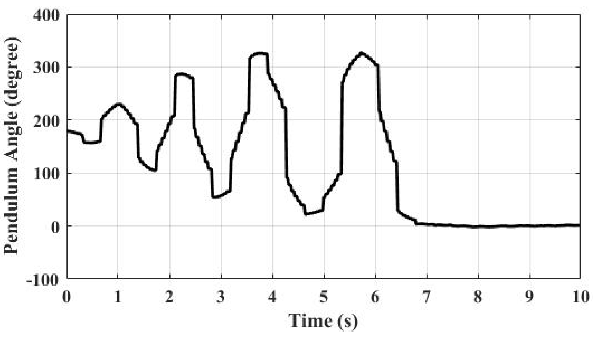
Figure 11 shows the angular position of the pendulum during the swing-up and the balancing motions. According to the results, it takes four swings for the pendulum to reach the unstable equilibrium position. The balancing controller does not have any overshoot and it has no steady state error as desired.
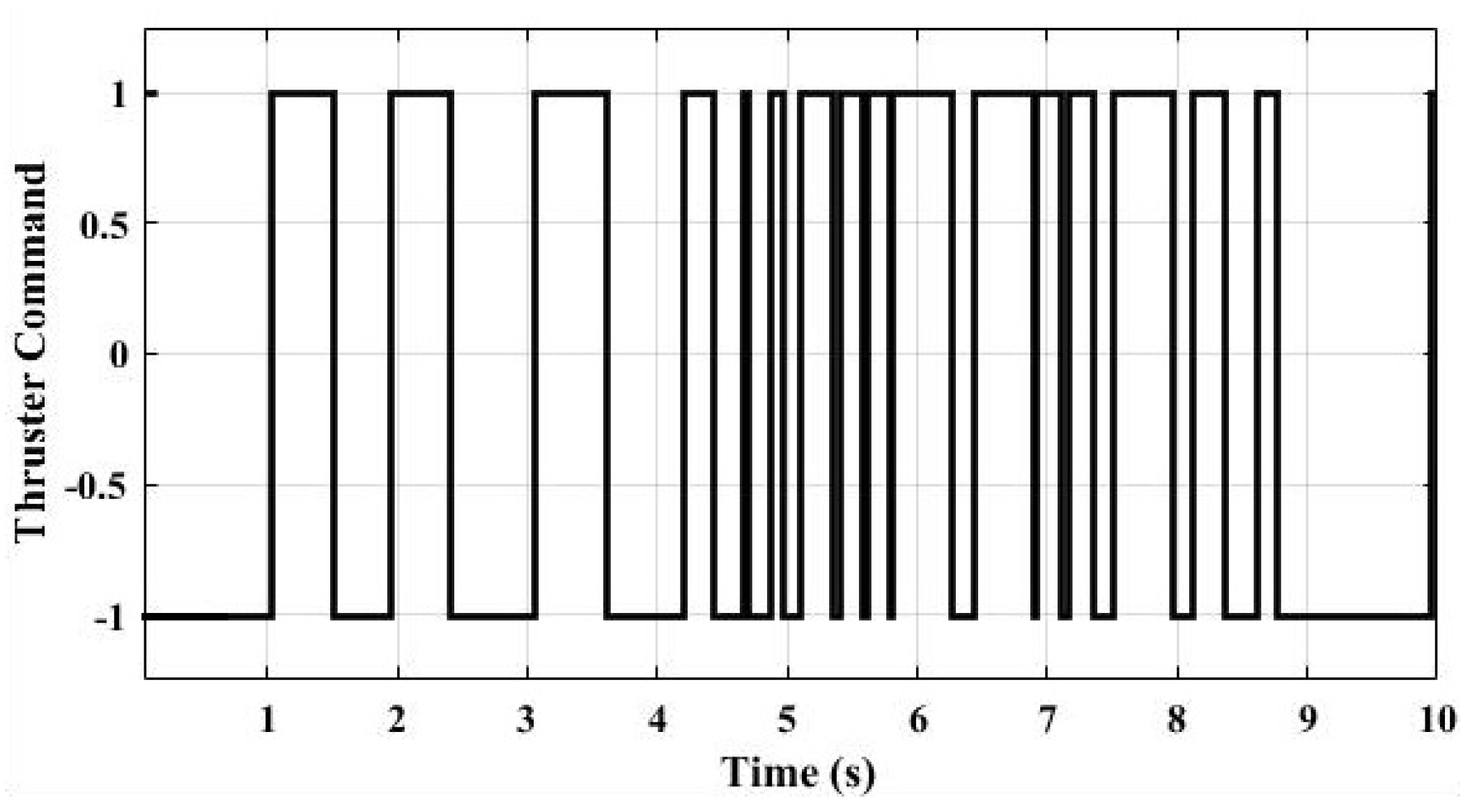
Figure 12 shows the thruster output during this motion.
The inverted pendulum test result is comparable with the simulation results provided in
Figure 4. The main reasons of the discrepancies between the model and the simulation are considered to be the piping and the slip ring.
6. Discussions
The best use of the proposed controller schemes in this work might be the multi-input multi-output (especially under-actuated ones) on–off thruster actuated spacecraft attitude control problems. For these kind of problems and to be able to control all the states simultaneously, independent torques are required for the three axes. If the system is completely state controllable, the controller for the system can be designed by linear state space analysis. Thus, required quasi-linear thrust can be obtained by proper PW modulator and sampler dynamics of the modulator can be taken into account by discrete analysis. The required fast response can be obtained for any angular position. Thruster-actuated vertical take off and landing (VTOL) vehicles might be the specific example of thruster actuated inverted pendulums. VTOL vehicles have similar dynamics, with inverted pendulums having additional freedoms, and the stabilization of them can be accomplished by side thrusters [
40].
PW linearized thrust outputs cannot be used in systems requiring high bandwidths. The approach followed in this study is only applicable on low bandwidth systems.
Inverted pendulum applications are accomplished with different types of actuators using different configurations. This work extends the topic by using another type of actuator with different dynamics. The used actuator brings an extra challenge, low frequency on–off actuator dynamics.
7. Conclusions
In this work, PWM actuated cold gas thrusters were used for the control of a rotary inverted pendulum. The relationship between the system bandwidth and the PWM frequency is examined. On–off cold gas thruster actuators were used for the first time on inverted pendulum systems.
Single axis angle control and inverted pendulum application were tested on the laboratory level test setups. Although a slip ring and rotary pneumatic joint were used to have less friction on the rotational motion, spring and damping effects of the piping and the pneumatic rotary joint were pretty effective. Under these circumstances, designed modulators and controllers were employed on both the single axis angular position and the rotary inverted pendulum control test setups. The performance of the controllers was satisfying. However, discrepancies are observed between the model and the experimentation results. It is evaluated that the major causes of the discrepancies are the friction and the spring effects.
Regarding future works, other equipment may also be modeled to observe the dynamics of each component. During modeling and tests, air is preferred as a propellant. Instead of air, widely used cold gas propellants like nitrogen or helium can be used in the upcoming studies. The control structure in this work is limited by a linear state feedback controller. Other nonlinear control topologies may also be applied.
Author Contributions
Conceptualization, Y.S. and U.Y.; methodology, Y.S. and U.Y.; implementation, Y.S.; validation, Y.S.; formal analysis, Y.S. and U.Y.; resources, Y.S.; writing—original draft preparation, Y.S. and U.Y.; writing—review and editing, U.Y.; visualization, Y.S. and U.Y.; supervision, U.Y. All authors have read and agreed to the published version of the manuscript.
Funding
This research received no external funding.
Conflicts of Interest
The authors declare no conflict of interest.
References
- Anis, A. Cold gas propulsion system-an ideal choice for remote sensing small satellites. In Remote Sensing-Advanced Techniques and Platforms; IntechOpen: Rijeka, Crotia, 2012. [Google Scholar]
- Ranjan, R.; Karthikeyan, K.; Riaz, F.; Chou, S. Cold gas propulsion microthruster for feed gas utilization in micro satellites. Appl. Energy 2018, 220, 921–933. [Google Scholar] [CrossRef]
- White, W.N.; Fales, R.C. Control of a double inverted pendulum with hydraulic actuation: A case study. In Proceedings of the 1999 American Control Conference (Cat. No. 99CH36251), San Diego, CA, USA, 2–4 June 1999; Volume 1, pp. 495–499. [Google Scholar]
- Muehlebach, M.; D’Andrea, R. Nonlinear analysis and control of a reaction-wheel-based 3-D inverted pendulum. IEEE Trans. Control. Syst. Technol. 2016, 25, 235–246. [Google Scholar] [CrossRef]
- Vazquez, R.; Gavilan, F.; Camacho, E.F. Trajectory planning for spacecraft rendezvous with on/off thrusters. IFAC World Congr. 2011, 18, 8473–8478. [Google Scholar] [CrossRef]
- Sakamoto, T.; Hori, N. New PWM schemes based on the principle of equivalent areas. In Proceedings of the IEEE International Symposium on Industrial Electronics, L’Aquila, Italy, 8–11 July 2002; pp. 505–510. [Google Scholar]
- Zimpfer, D.J.; Shieh, L.S.; Sunkel, J.W. Digitally redesigned pulse-width modulation spacecraft control. J. Guid. Control. Dyn. 1998, 21, 529–534. [Google Scholar] [CrossRef]
- Bernelli-Zazzera, F.; Mantegazza, P. Pulse-width equivalent to pulse-amplitude discrete control of linearsystems. J. Guid. Control. Dyn. 1992, 15, 461–467. [Google Scholar] [CrossRef]
- Alcorn, J.; Schaub, H.; Piggott, S. Steady-State Attitude and Control Effort Sensitivity Analysis of Discretized Thruster Implementations. J. Spacecr. Rocket. 2017, 54, 1161–1169. [Google Scholar] [CrossRef]
- Howells, G.; Gillham, M. Attitude Control of Small Probes for De-orbit, Descent and Surface Impact on Airless Bodies Using a Single PWM Thruster. In Proceedings of the 2017 6th International Conference on Space Mission Challenges for Information Technology (SMC-IT), Madrid, Spain, 27–29 September 2017. [Google Scholar]
- Mazinan, A.; Pasand, M.; Soltani, B. Full quaternion based finite-time cascade attitude control approach via pulse modulation synthesis for a spacecraft. ISA Trans. 2015, 58, 567–585. [Google Scholar] [CrossRef]
- Suzuki, T.; Ueno, T.; Hori, N. Experimental verification of pea-based pwm control using on-off type air-jet thrusters. In Proceedings of the International Conference on Information and Automation, Barcelona, Spain, 18–22 April 2005; pp. 1–6. [Google Scholar]
- Jeon, S.W.; Jung, S. Hardware-in-the-loop simulation for the reaction control system using PWM-based limit cycle analysis. IEEE Trans. Control. Syst. Technol. 2012, 20, 538–545. [Google Scholar] [CrossRef]
- Bals, J.; Kienitz, K. A comprehensive approach to pulse modulation for attitude control with thrusters subject to switching restrictions. In Proceedings of the DGLR Annual Conference, Oberpfaffenhofen, Germany, 26–29 September 2005. [Google Scholar]
- Taghizadeh, M.; Ghaffari, A.; Najafi, F. Modeling and identification of a solenoid valve for PWM control applications. Comptes Rendus Mec. 2009, 337, 131–140. [Google Scholar] [CrossRef]
- Topçu, E.E.; Yüksel, İ.; Kamış, Z. Development of electro-pneumatic fast switching valve and investigation of its characteristics. Mechatronics 2006, 16, 365–378. [Google Scholar] [CrossRef]
- Matsumoto, T.; Kita, K.; Suzuki, R.; Oosedo, A.; Go, K.; Hoshino, Y.; Konno, A.; Uchiyama, M. A hovering control strategy for a tail-sitter VTOL UAV that increases stability against large disturbance. In Proceedings of the 2010 IEEE International Conference on Robotics and Automation, Anchorage, AK, USA, 3–7 May 2010; pp. 54–59. [Google Scholar]
- Andrievsky, B. Global stabilization of the unstable Reaction-Wheel Pendulum. Autom. Remote. Control. 2011, 72, 1981. [Google Scholar] [CrossRef]
- Adler, J.M.; Lee, M.S.; Saugen, J.D. Adaptive control of propellant slosh for launch vehicles. Sensors Sens. Integr. Int. Soc. Opt. Photonics 1991, 1480, 11–23. [Google Scholar]
- Bandyopadhyay, B.; Kurode, S.; Gandhi, P. Sliding mode control for slosh-free motion-A class of underactuated system. Int. J. Adv. Mechatron. Syst. 2009, 1, 203–213. [Google Scholar] [CrossRef]
- Bandyopadhyay, B.; Gandhi, P.; Kurode, S. Sliding mode observer based sliding mode controller for slosh-free motion through PID scheme. IEEE Trans. Ind. Electron. 2009, 56, 3432–3442. [Google Scholar] [CrossRef]
- Cho, S.; McClamroch, M.; Reyhanoglu, M. Feedback control of a space vehicle with unactuated fuel slosh dynamics. In Proceedings of the AIAA Guidance, Navigation, and Control Conference and Exhibit, Dever, CO, USA, 14–17 August 2000; p. 4046. [Google Scholar]
- Hervas, J.R.; Reyhanoglu, M. Thrust-vector control of a three-axis stabilized upper-stage rocket with fuel slosh dynamics. Acta Astronaut. 2014, 98, 120–127. [Google Scholar] [CrossRef]
- Kumar, E.V.; Jerome, J. Robust LQR controller design for stabilizing and trajectory tracking of inverted pendulum. Procedia Eng. 2013, 64, 169–178. [Google Scholar] [CrossRef]
- Chen, C.S.; Chen, W.L. Robust adaptive sliding-mode control using fuzzy modeling for an inverted-pendulum system. IEEE Trans. Ind. Electron. 1998, 45, 297–306. [Google Scholar] [CrossRef]
- Wai, R.J.; Chang, L.J. Adaptive stabilizing and tracking control for a nonlinear inverted-pendulum system via sliding-mode technique. IEEE Trans. Ind. Electron. 2006, 53, 674–692. [Google Scholar]
- El-Hawwary, M.I.; Elshafei, A.L.; Emara, H.M.; Fattah, H.A.A. Adaptive fuzzy control of the inverted pendulum problem. IEEE Trans. Control. Syst. Technol. 2006, 14, 1135–1144. [Google Scholar] [CrossRef]
- Furuta, K.; Yamakita, M.; Kobayashi, S. Swing up control of inverted pendulum. In Proceedings of the IECON’91: 1991 International Conference on Industrial Electronics, Control and Instrumentation, Kobe, Japan, 28 October–1 November 1991; pp. 2193–2198. [Google Scholar]
- Yang, X.; Zheng, X. Swing-up and stabilization control design for an underactuated rotary inverted pendulum system: Theory and experiments. IEEE Trans. Ind. Electron. 2018, 65, 7229–7238. [Google Scholar] [CrossRef]
- Sainzaya, G.; Yu, F.N.; Hsieh, T.L.; Yang, C.Y. LQR control with refined PID to balance rotary inverted pendulum with time-varying uncertainty. In Proceedings of the 2017 International Conference on Fuzzy Theory and Its Applications (iFUZZY), Yilan, Taiwan, 13–16 November 2017; pp. 1–6. [Google Scholar]
- Spong, M.W.; Corke, P.; Lozano, R. Nonlinear control of the reaction wheel pendulum. Automatica 2001, 37, 1845–1851. [Google Scholar] [CrossRef]
- Scalera, L.; Gasparetto, A.; Zanotto, D. Design and experimental validation of a 3-dof underactuated pendulum-like robot. IEEE/ASME Trans. Mechatronics 2019, 25, 217–228. [Google Scholar] [CrossRef]
- García-Sánchez, J.R.; Tavera-Mosqueda, S.; Silva-Ortigoza, R.; Hernández-Guzmán, V.M.; Sandoval-Gutiérrez, J.; Marcelino-Aranda, M.; Taud, H.; Marciano-Melchor, M. Robust switched tracking control for wheeled mobile robots considering the actuators and drivers. Sensors 2018, 18, 4316. [Google Scholar] [CrossRef] [PubMed]
- Martinez, D.I.; De Rubio, J.J.; Vargas, T.M.; Garcia, V.; Ochoa, G.; Balcazar, R.; Cruz, D.R.; Aguilar, A.; Novoa, J.F.; Aguilar-Ibañez, C. Stabilization of Robots With a Regulator Containing the Sigmoid Mapping. IEEE Access 2020, 8, 89479–89488. [Google Scholar] [CrossRef]
- Petric, J.; Situm, Z. Inverted pendulum driven by pneumatics. Int. J. Eng. Educ. 2003, 19, 597–602. [Google Scholar]
- Žilić, T.; Pavković, D.; Zorc, D. Modeling and control of a pneumatically actuated inverted pendulum. ISA Trans. 2009, 48, 327–335. [Google Scholar] [CrossRef]
- Shenghao, Z.; Jinchun, S. Intelligent predictive fuzzy control for pneumatic inverted pendulum. In Proceedings of the 2011 6th IEEE Conference on Industrial Electronics and Applications, Beijing, China, 21–23 June 2011; pp. 968–972. [Google Scholar]
- Åström, K.J.; Furuta, K. Swinging up a pendulum by energy control. Automatica 2000, 36, 287–295. [Google Scholar] [CrossRef]
- George, J.; Krishna, B.; George, V.; Shreesha, C.; Menon, M.K. Stability analysis and design of PI controller using Kharitnov polynomial for rotary inverted pendulum. MANIPAL 2012, 138, 104–113. [Google Scholar]
- Blackmore, L. Autonomous precision landing of space rockets. In Proceedings of the Frontiers of Engineering: Reports on Leading-Edge Engineering from the 2016 Symposium, Mabel Beckman Center, Irvine, CA, USA, 19–21 September 2016; Volume 46, pp. 15–20. [Google Scholar]
© 2020 by the authors. Licensee MDPI, Basel, Switzerland. This article is an open access article distributed under the terms and conditions of the Creative Commons Attribution (CC BY) license (http://creativecommons.org/licenses/by/4.0/).


