Article

Active Motion Control of a Knee Exoskeleton Driven by Antagonistic Pneumatic Muscle Actuators

School of Instrument Science and Engineering, Southeast University, Nanjing 210096, China
*
Author to whom correspondence should be addressed.
Actuators 2020, 9(4), 134; https://doi.org/10.3390/act9040134
Submission received: 28 October 2020 / Revised: 28 November 2020 / Accepted: 7 December 2020 / Published: 10 December 2020
(This article belongs to the Section Actuators for Medical Instruments)

Abstract

:
The pneumatic muscle actuator (PMA) has been widely applied in the researches of rehabilitation robotic devices for its high power to weight ratio and intrinsic compliance in the past decade. However, the high nonlinearity and hysteresis behavior of PMA limit its practical application. Hence, the control strategy plays an important role in improving the performance of PMA for the effectiveness of rehabilitation devices. In this paper, a PMA-based knee exoskeleton based on ergonomics is proposed. Based on the designed knee exoskeleton, a novel proxy-based sliding mode control (PSMC) is introduced to obtain the accurate trajectory tracking. Compared with conventional control approaches, this new PSMC can obtain better performance for the designed PMA-based exoskeleton. Experimental results indicate good tracking performance of this controller, which provides a good foundation for the further development of assist-as-needed training strategies in gait rehabilitation.

1. Introduction

The knee joint is the most susceptible joint of the lower limb joint for human beings [1]. It plays an important role in human motion, such as supporting body weight, absorbing strike shock, and assisting the swing of lower limbs [2]. But movement impairment of knee joint, which is commonly characterized by spastic muscle tone or leg muscle weakness, may have a great influence on the activities of daily life (ADL). The main causes of knee impairment include cerebral palsy, incomplete spinal injury, and stroke. Traditional physical treatments are conducted by therapists, which are time-consuming and expensive. The heavy burden for therapists may have negative effects on the treatments. In recent years, the powered assistive devices have emerged as an alternative option for effective physical therapy and attracted plenty of scientific researches [3].
The exoskeleton is one of the most common powered assistive devices for rehabilitation. Most of the exoskeletons consist of rigid structures which are actuated by electric motors assembled with the transmissions [4,5,6]. The rigid exoskeletons are characterized by high force output and good controllability as the merits. However, the widespread application of rigid exoskeletons is still limited for poor compliance, large weight/inertia, and degrading metabolic efficiency or safety [7,8]. Recent researches on soft robotics have provided new approaches for the design of exoskeletons, i.e., soft exoskeletons [9]. The utilization of soft actuators, soft structural materials, and soft sensors have improved the performance of exoskeletons [10,11,12,13,14]. The soft actuators such as the pneumatic artificial muscles (PMA), shape memory alloys, and the electroactive polymer actuators play an important role in the design of soft exoskeletons [15,16,17,18]. Pneumatic artificial muscles have been widely used as soft actuators for the intrinsic compliance and high force to weight ratio [19,20,21,22,23]. For the unidirectional actuation of PMA, the exoskeletons are often designed in antagonistic configurations with two PMAs to realize bilateral rotations [24,25,26]. Despite the advantages, the highly nonlinear dynamics of PMA makes it challenging to apply precise control.
To improve the accuracy of joint trajectory tracking for a PMA-based exoskeleton, various control strategies have been studied in recent decades. Xiong et al. utilized a feedback and feedforward proportional–integral–derivative (PID) controller to track the desired output of the arm exoskeleton [27]. A PID controller was also used by Van Damme to correct disturbances of the pneumatic manipulator [28]. In spite of easy implementation, the convergence analysis and coefficients adjustment limit the use of PID control. The soft-computing techniques have been studied in recent years, such as fuzzy sets and artificial neural networks (ANNs), etc. A fuzzy controller combined with a bang-bang controller was proposed for the PMA-based elbow exoskeleton [29]. Chang introduced an adaptive self-organizing fuzzy controller for the rehabilitation robot [30]. Huang showed ANNs-based model predictive control (MPC) methods to obtain accurate control performance [31,32]. Despite the capability of approximating nonlinear characteristics, the high computation confines real-time performance and limits PMA control applications. Addressing the dynamics of PMA, sliding mode control (SMC) might be a suitable method for its robustness to internal system uncertainties as well as the external disturbances. Shen applied an SMC to the designed PMA-based servo system to obtain robust control [33]. An SMC was also applied into the PMA-based lower limb exoskeleton to verify the compliance [34]. Aschemann et al. showed a cascaded SMC scheme for the PMA-based linear axis [35]. However, the “chattering” problem of PMA may cause damages to the actuators.
In recent years, a “proxy” is added to the conventional SMC as an extension of PID control, i.e., proxy-based sliding mode control (PSMC) [36]. The PSMC can avoid the “chattering” problem and generate an overdamped resuming motion from big errors of position without sacrificing tracking accuracy. The PSMC has been applied in PMA control [37] and other application fields [38]. However, there is still room to improve the PSMC from the general theoretical framework like extending the designing of virtual coupling.
In this paper, a PMA-based knee exoskeleton based on ergonomics is proposed. Based on the designed knee exoskeleton, a novel PSMC is introduced to obtain the accurate trajectory tracking. Compared with conventional control approaches, this new PSMC can obtain better performance for the designed PMA-based exoskeleton.
The rest of this paper is organized as follows. Section 2 analyzes the design requirements based on ergonomics and illustrates the structure of the designed knee exoskeleton. Section 3 introduces the novel EPSMC for the PMA-based exoskeleton. In Section 4, a series of experiments are conducted to verify the performance of the new controller. Section 5 provides the conclusion.

2. The PMA-Based Knee Exoskeleton

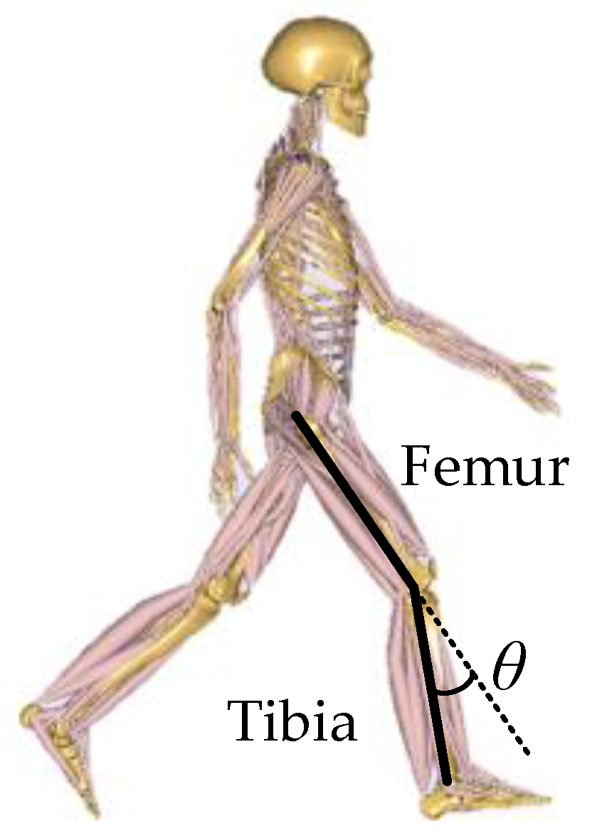
2.1. Ergonomic Baiscs and Design Requirements

The ergonomics should be primarily considered for the design requirements of the knee exoskeleton. The literatures on the kinematic and dynamic of the knee joint in common movement forms are investigated [39,40], as illustrated in Figure 1. The angle θ is defined as a flexion between the femur and the tibia in sagittal plane. The joint angle θ is defined to be 0 when the center line of the femur coincides with that of the tibia, i.e., the knee is fully extended, and it increases when the knee joint flexes.
The designed knee exoskeleton focuses on the rehabilitation of patients with knee injuries, so the application scenarios are mainly moderate knee movements. The brief biomechanical data of knee joint movement are listed in Table 1.
According to Table 1, although the maximum flexion angle for the knee joint is 150.4°, but the exoskeletons within the angle range are often portable devices, which aims to provide assistance in activities in daily life (ADL). The more professional rehabilitation devices mainly focus on the “walking” motion, such as the Lokomat system (Hocoma AG). To extend the rehabilitation scenarios, the angle range of a designed PMA-based exoskeleton is set to 90 ° which is around the stair ascending or descending motion angle. In addition, in order to avoid side effects like muscle atrophy, it is enough to provide the knee joint with a partial assistance of the peak torque during various human movements [41].

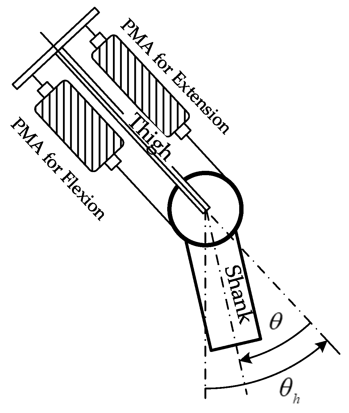
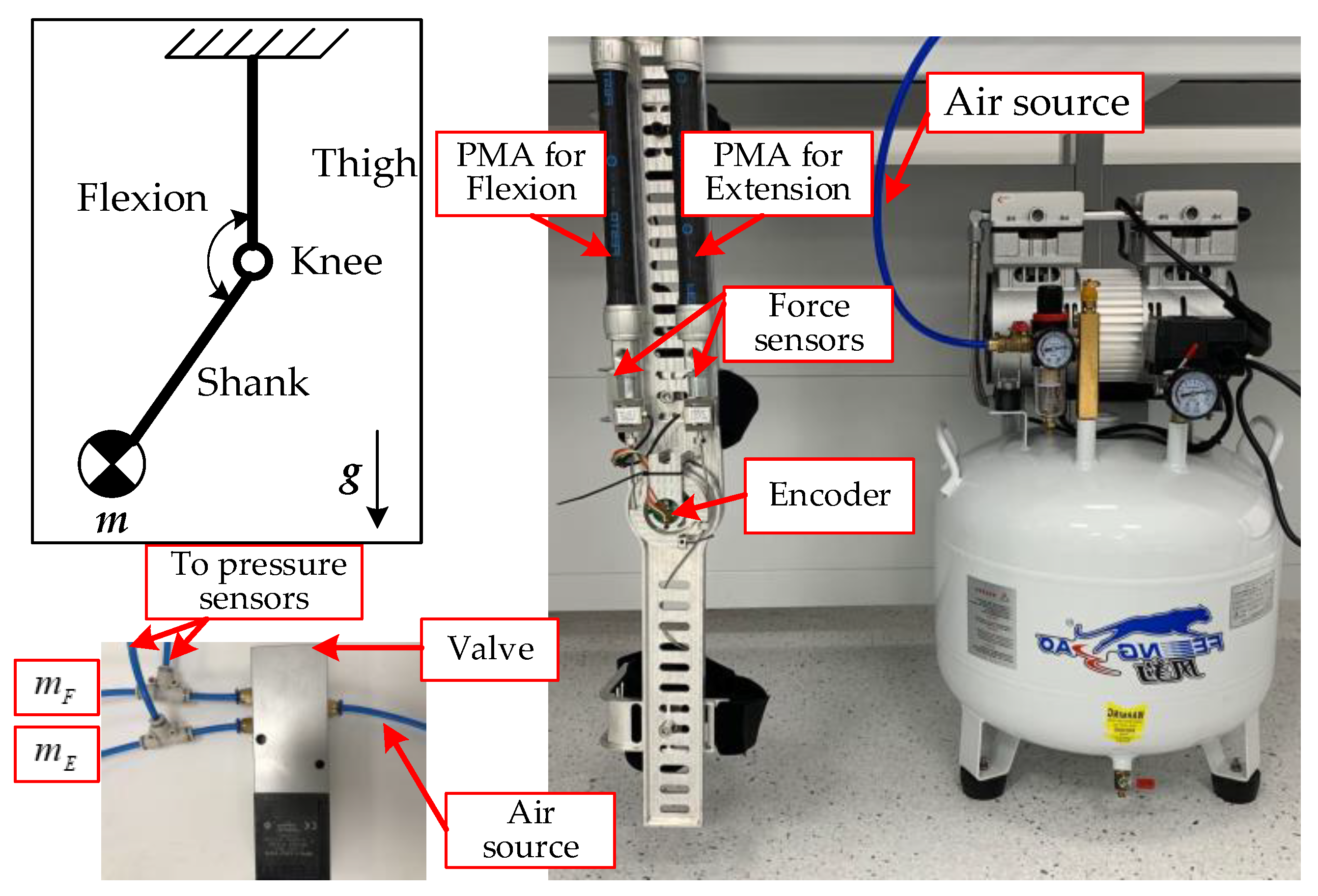
2.2. The Mechanical System of PMA-Driven Exoskeleton

The knee joint, i.e., the flexion and extension movement, is powered by two antagonistic PMAs. The two PMs actuate the rotational knee joint via 3mm diameter steel cables with a 30-mm moment arm. Each PMA is connected to the structure basis through a force sensor to detect the real-time force information. An angular encoder is mounted along the joint axis to measure the angular position of the knee joint. The brief schematic drawing of the mechanism is illustrated in Figure 2. The knee joint θ is set to be zero when the center lines of thigh and shank segments coincide and increases as the joint flexes.
For the antagonistic configuration, the difference between flexion and extension muscles generates the angle motion. Assuming that the cables are always in tension and neglect the stretch, the contracting lengths of the antagonistic actuators are expressed by
x F = r ( θ θ F 0 ) x E = r ( θ E 0 θ )
where r represents the joint moment arm, and θ F 0 and θ E 0 are the knee joint positions when the pair actuators have no extension or contraction.

3. Design of the Active Motion Controller

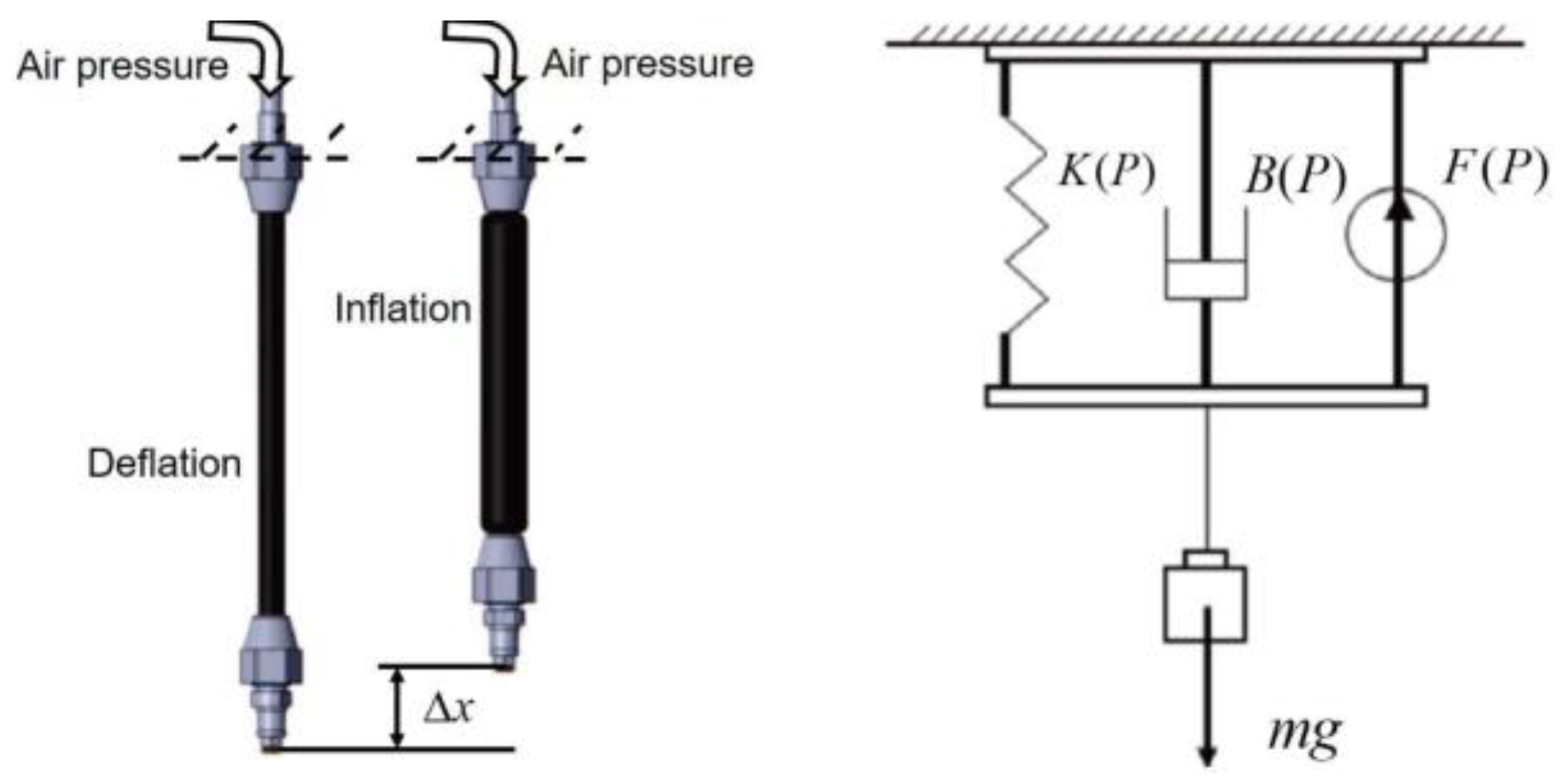
3.1. Modeling of PMA

The FESTO AG Company’s PMAs are chosen as the actuator of the designed knee rehabilitation device. The existence of the pressurized air, the elastic viscous material, and the geometric features of PMA gives rise to the high nonlinearities, so it’s of great importance to choose the suitable mathematical PMA model. Two main categories are prevalently used for the mathematical models, the theoretical model and the phenomenological model. In this article, the phenomenological model is utilized as a combination of effects from nonlinear friction, spring, and contraction components to describe the dynamic behavior of a PM pulling a mass against gravity, as shown in Figure 3.
Considering the bandwidth requirement of gait rehabilitation robot system, the dynamic model should be developed as described in [42] instead of the static modeling methods. The dynamics of the PMA are approximately given as follows:
M x ¨ + B ( P ) x ˙ + K ( P ) x = F ( P ) M g
K ( P ) = K 0 + K 1 P
B ( P ) = B 0 i + B 1 i P   ( inflation )  
B ( P ) = B 0 d + B 1 d P   ( deflation )
F ( P ) = F 0 + F 1 P
where M is the mass of PMA, g is the acceleration of gravity, P represents the input pressure, x = 0 corresponds to the fully deflated position of PMA, and K(P) and B(P) are pressure-dependent coefficients representing the spring and damping elements respectively, which can be determined experimentally.
x ¨ = f ( x , x ˙ ) + b ( x , x ˙ ) u ( t ) + d ( x , x ˙ , t )
where
f ( x , x ˙ ) = 1 M [ F 0 B 0 x ˙ K 0 x M g ]
b ( x , x ˙ ) = 1 M [ F 1 B 1 x ˙ K 1 x ]
and
{ B 0 = B 0 i   ,   B 1 = B 1 i   i f   x ˙ > 0   ( i n f l a t i o n ) B 0 = B 0 d   ,   B 1 = B 1 d   i f   x ˙ > 0   ( d e f l a t i o n ) B 0 ,   B 1   h o l d   i f   x ˙ = 0   .
The uncertainties including external disturbances and modeling errors are lumped into the term d ( x , x ˙ , t ) in Equation (6).
Then, the torque generated by each actuator is calculated by
{ τ F = ( F ( P F ) + K ( P F ) x F + B ( P F ) x ˙ F ) · r τ E = ( F ( P E ) + K ( P E ) x E + B ( P E ) x ˙ E ) · r
τ t o t a l = τ F τ E = ( F ( P F ) K ( P F ) x F B F ( P F ) x ˙ F F ( P E ) + K ( P E ) x E ( P E ) x ˙ E ) r .

3.2. Modeling of the System

The pressure regulators are used to be black boxes in some control loops, but this application ignores the details of pressure characteristics of the PM actuator, which may causes time delays or unpredictable errors [43,44]. Modeling including the force dynamics of mechanism and actuators, flow dynamics and pressure could better describe the entire system [33]. The pressure dynamics in the PM can be described as follows:
m ˙ = 1 R T ( V p ˙ k + p V ˙ )
V F = 2 a 3 + 2 a 1 r 2 ( θ F 0 θ ) 2 2 a 2 r ( θ F 0 θ )
V E = 2 a 3 + 2 a 1 r 2 ( θ E 0 θ ) 2 2 a 2 r ( θ E 0 θ )
where m ˙ is the pneumatic mass flow of the PM, R is the universal gas constant, T represents the gas temperature, and V F , V E represent volume of the flexion and extension-side PM. V could be modeled as a function of muscle contraction length x and transformed into the form of knee joint θ . The coefficients a 1 , a 2 and a 3 can be determined experimentally.
The proportional valves are used to control the mass flow in each PM. The flow characteristics of proportional can be modeled based on the related parameters as follows:
m ˙ 0 ( p u , p d ) = { p u C ρ 0 T 0 / T u 1 ( p d / p u b ) ( 1 b ) if   p d p u > b p u C ρ 0 T 0 / T u if   p d p u > b
m ˙ = A · m ˙ 0 ( p u , p d )
where m ˙ 0 represents the maximum mass flow for given pressures over a fully opened valve. p u and p d denote the up and downstream pressure of PM. ρ 0 , T 0 represent the density and temperature in the ISO 6358 reference state, C is the sonic conductance, and b is the critical pressure ratio. The actual mass flow m ˙ of PM is controlled by the voltage signals according to the valve characteristics.
The entire system can be modeled by combining the mentioned models, and it includes two inputs of valve flow control, two outputs of knee joint θ and the pressure in flexion side PM. The vectors of variables, control inputs, and outputs are listed as follows.
Combing (13) and (16), the model can be written in the form as follows:
x _ = [ θ θ ˙ P F P E ] T = [ x 1 x 2 x 3 x 4 ]
u = A F / E
y = θ = x 1 .
The Lie derivative is used to perform the coordinate transformation into a new expression form to control the position without a degradation of the desired specifications. The sliding mode algorithm can be studied based on the coordinate transformation. L f h ( x ) is the directional derivative of scalar h ( x ) and the properties are described in (21)
{ L f h ( x ) = h ( x ) x f ( x ) L f 2 h ( x ) = L f L f h ( x ) = ( L f h ( x ) ) x f ( x ) L f k h ( x ) = L f ( L f k 1 h ( x ) ) = ( L f k 1 h ( x ) ) x f ( x ) .
Based on (21), the new state variable vector is selected as (22), and its time derivative is calculated with (23).
z _ = φ ( x ) = [ h 1 ( x _ ) = x 1 L f h 1 ( x _ ) = x 2 L f 2 h 1 ( x _ ) = x ˙ 2 h 2 ( x _ ) = x 3 ]
z _ ˙ = [ θ ˙ θ ¨ L f 3 h 1 ( x _ ) + L g 1 L f 2 h 1 ( x _ ) u 1 + L g 2 L f 2 h 1 ( x _ ) u 2 L f h 2 ( x _ ) + L g 1 h 2 ( x _ ) u 1 ]

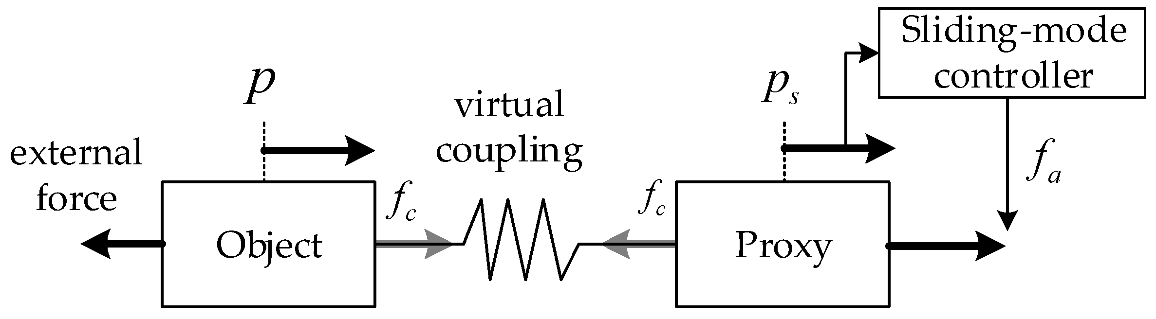
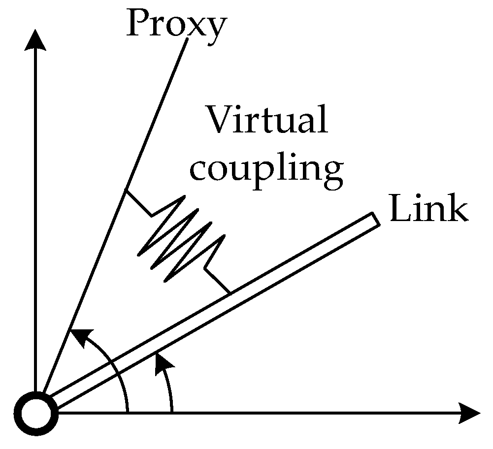
3.3. Extended Proxy-Based SMC Design

In classical SMC, the “chattering” phenomenon is one important issue that needs to be solve, which is caused by the sign function. So, a virtual object called “proxy” is applied to reduce the phenomenon in the PSMC strategy [36], as illustrated in Figure 4. The proxy connects the physical actuator and the desired position, and one “virtual coupling” connects the proxy with the actuator. The virtual coupling can be seen as an imaginary spring-like element which exerts a specific force to maintain the length to zero. The proxy has the capability to simulate ideal motion, which satisfies idealized physical constraints. A PID controller is usually introduced for the virtual coupling to affect the physical object and reduce the “chattering” to a great extent.
The PSMC in the form of depicting rotation movement is shown in Figure 5. The proxy can be described as a torsional PID-type virtual coupling attached to a single robot link [24].
According to the illustration of PSMC in Figure 4, the sliding mode controller determines the force f a , which is then applied into the virtual proxy. And the force produced by the PID-type virtual coupling is defined as f c which is applied to the real controlled object. Then, the motion of proxy can be calculated as:
m p ¨ = f a f c .
After that, we can have the sliding manifold as:
{ σ p = θ ˙ d p ˙ + H ( θ d p ) σ θ = θ ˙ d θ ˙ + H ( θ d θ ) .
To obtain a stable extended PSMC for the system (12), the novel sliding manifolds are designed as:
{ σ p = θ ˙ d p ˙ + H ( θ d p ) + I ( θ d p ) d t σ θ = θ ˙ d θ ˙ + H ( θ d θ ) + I ( θ d θ ) d t .
It should be noted that the proposed manifolds contain integrals of ( θ d p ) and ( θ d θ ) compared with the conventional PSMC. The integral parts play an important role in reducing the steady error for the tracking control. Based on this, the virtual coupling force f c and the sliding mode controller f S M C are calculated as:
{ f c = 1 b [ K p ( p θ ) f + θ ¨ d + H ( θ ˙ d θ ˙ + I ( θ d θ ) ] f S M C = Γ s g n ( σ p ) K p ( p θ ) + m p θ ¨ d + m p H ( θ ˙ d p ˙ ) + m p I ( θ d p ) + 1 b [ K p ( p θ ) f + θ ¨ d + H ( θ ˙ d θ ˙ ) + I ( θ d θ ) ] .
Some terms based on the dynamics are added to the coupling force f c and the sliding mode controller f S M C for the convenience of theoretical analysis. Then, the closed-loop system model is given by:
{ θ ¨ = K p ( p θ ) + θ ¨ d + H ( θ ˙ d θ ˙ ) + I ( θ d θ ) m p p ¨ = f S M C f c = Γ s g n ( σ p ) K p ( p θ ) + m p θ ¨ d + m p H ( θ ˙ d p ˙ ) + m p I ( θ d p ) .
The stability of the system can be verified by constructing the following function:
{ V 1 = 1 2 m p σ p 2 V 2 = 1 2 σ θ 2 V 3 = K p ( p θ ) ( p ˙ θ ˙ ) + K p I ( p θ ) ( p θ ) d t .
The Lyapunov function is selected as:
V = V 1 + V 2 + V 3 .
Then, the derivative of Lyapunov function is calculated:
V ˙ = V ˙ 1 + V ˙ 2 + V ˙ 3 = Γ | σ p | K p H ( p θ ) 2 0 .
So, the system trajectory will finally be driven into the designed sliding mode manifolds, and the tracking error will converge to zero.

4. Experiment Validation

4.1. Parameters Determinations

According to the dynamics of PMA, the parameters are approximate to be linear with the inner pressure of the actuator. The parameters play an important role in studying the controlling strategies. To obtain the appropriate parameters for the model of chosen PMA in the exoskeleton, a series of experiments were conducted with the pressure ranging from 0.6 to 6 bar at the increments of 0.2 bar. The best fitting parameters were determined by utilizing the least square linear regression method [45]. Based on the experimental data analysis, the parameters are described by (15), which agree with the work in [34] that a piecewise model can better describe the difference between low and high pressure.
{ F ( P ) = 194.8 + 204.0 P K ( P ) = 63382 + 25085 P   ( 0.6 P 2 bar ) K ( P ) = 16352 787.9 P   ( 2 P 6 bar ) B ( P ) = 6275 + 946.4 P   ( Inflation ) B ( P ) = 763.9 91.04 P   ( Deflation )

4.2. Experiment Settings

The validation experiments should be conducted before the practical application in human body. To simulate the load from human leg, a mass ranging from 1kg to 4 kg with increments of 1 kg is attached to the end of shank part, as illustrated in Figure 6. The other side of exoskeleton is fixed to a platform.
To verify the performance of the proposed method, two kinds of reference trajectory were selected, i.e., the sinusoidal signal and actual knee motion signal. The sinusoidal signal is shown in (16).
θ d = A sin ( 2 π f t )
where A = 60, f = 0.25 Hz. The sinusoidal trajectory corresponds to the bidirectional motion of flexion and extension. It should be noted that the designed exoskeleton can be applied in either side of lower limb, so it makes sense to utilize the symmetrical trajectory. The actual knee motion provides another reference trajectory which was obtained from the Anybody Modeling System (Anybody, The Netherlands) with the standard model of 1.8 m in height.
The maximum absolute error and the integral were calculated to measure the accuracy of control results:
{ M a x E r r o r = M a x ( | θ d ( t ) θ ( t ) | t = 1 n ) I n t e l E r r o r = 1 n t = 1 n | θ d ( t ) θ ( t ) |
where n represents the total sample of experiment.
The xPC target developed by Mathworks Inc was used as the real-time part of the experiment platform. The main hardware includes the PMAs, air compressor, valves and the sensors, as listed in Table 2.

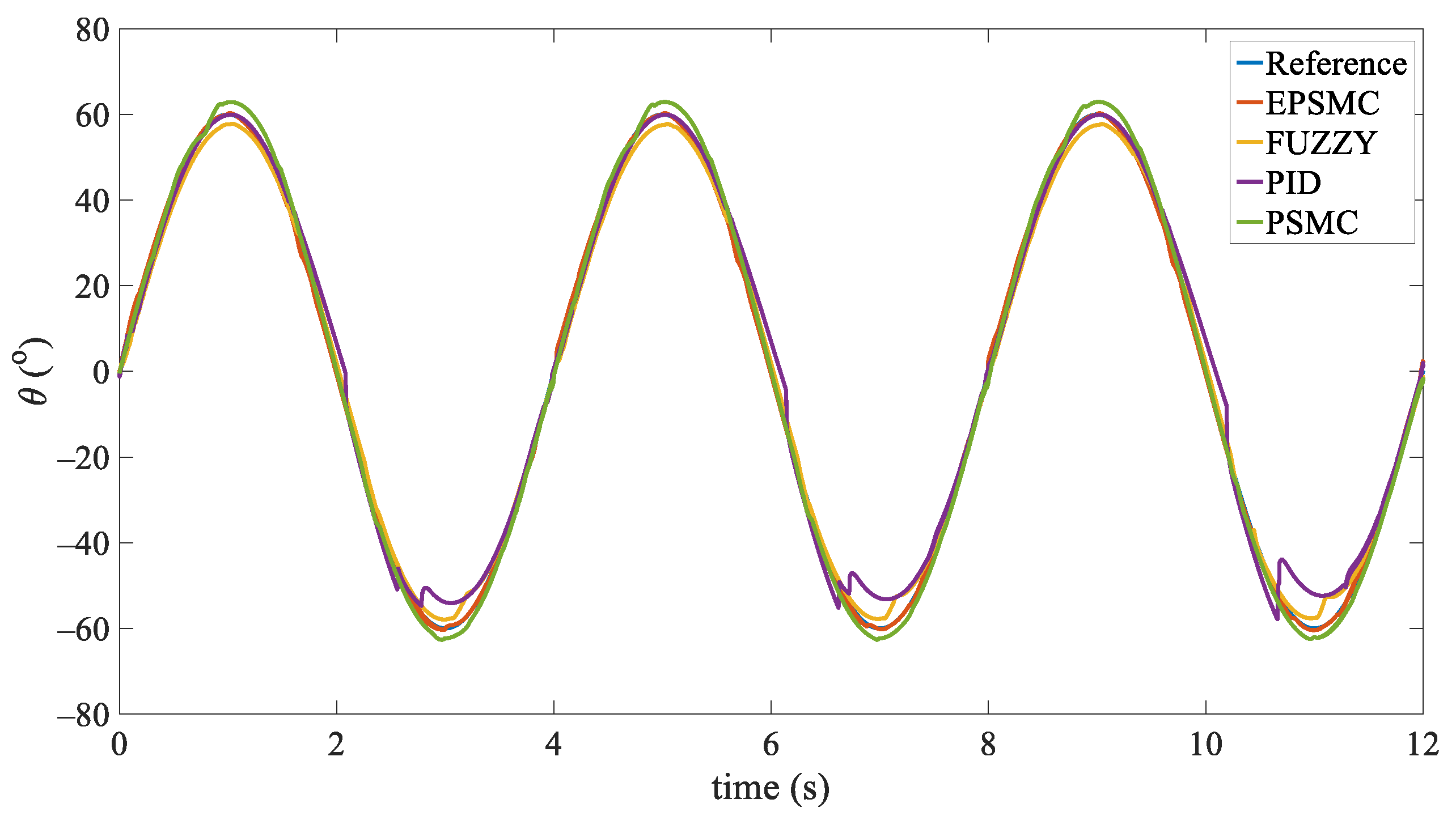
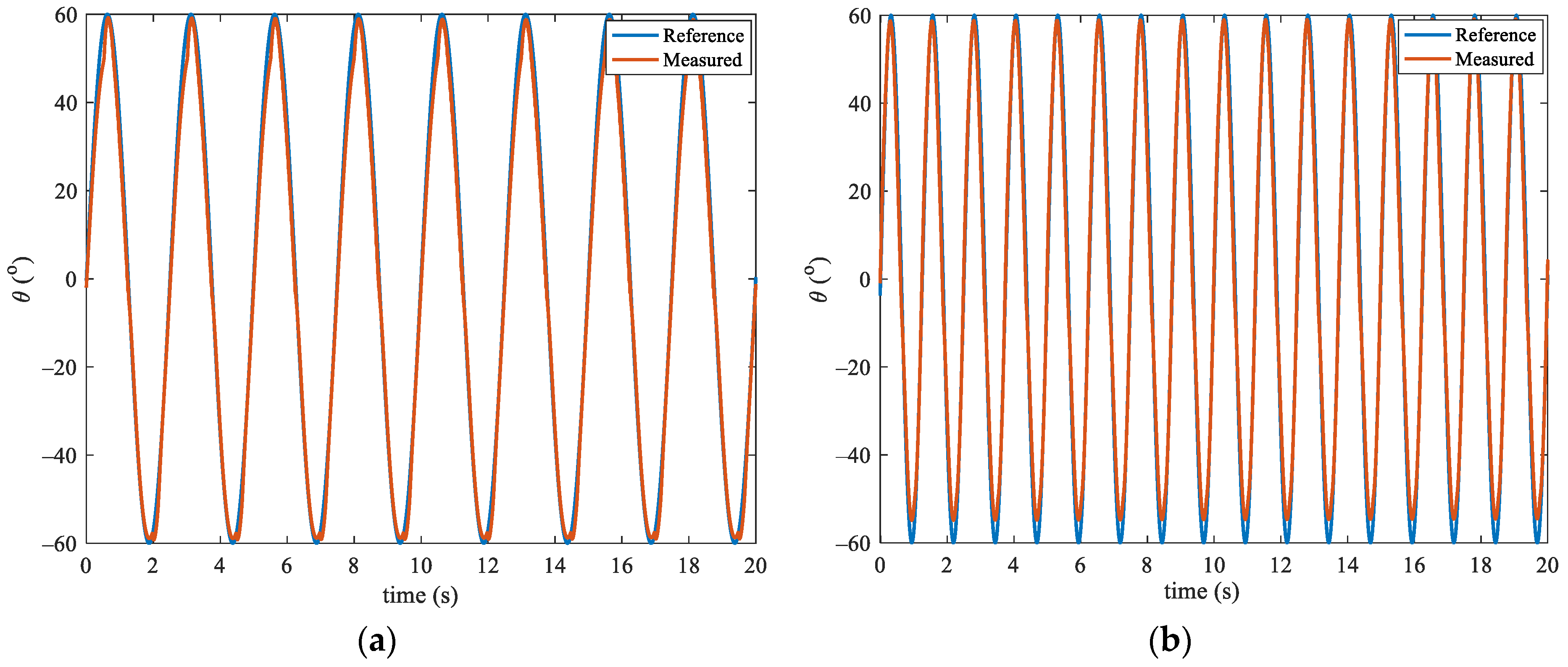
4.3. Experiment Results

To verify the performance of the PMA-based exoskeleton under the proposed controller, the same experiments using PSMC, PID and FUZZY control were also conducted as the comparisons. Furthermore, the ESPMC was applied under different loads to investigate the robustness of the system. The control parameters are tuned based on PMA with no loads, and the parameters of PSMC and EPSMC keep the same to verify the performance.
The tracking performance for the sinusoidal signal with different control strategies is shown in Figure 7, and the comparison result is shown in Table 3. As is illustrated in Figure 7, around the extreme point of desired trajectory, the tracking trajectories for each control strategy start to fluctuate, which affects the tracking performances. The PSMC and EPSMC can track the desired trajectory better than the other control strategies, but the tracking trajectory of EPSMC is more consistent with desired trajectory. The detailed evaluation with ‘MaxError’ and ‘IntelError’ are calculated in Table 3. The result shows that the EPSMC behaves best since it can reduce the “chattering” phenomenon significantly.
The gait rehabilitation training needs to be task specific, so the controller and the hardware system need to be able to operate at a bandwidth that is similar to the average gait cycle frequency (0.67 Hz) of stroke survivors [46]. The experiment was conducted with the same setup as the first experiment, but with joint movement frequency at 0.4 Hz and 0.8 Hz. To further investigate the robustness of the proposed method, a mass ranging from 1kg to 4 kg with increments of 1 kg is attached to the end ofshank part. The result is shown in Figure 8 and Table 4. The IntelError of tracking errors under 0.4Hz and 0.8 Hz are almost the same, but the MaxError of 0.4 Hz and 0.8 Hz are 2.6 ° and 5.1 ° , respectively. So, it concludes that the tracking errors increase with the frequency, which may be caused by the intrinsic compliance of the PM that increases the phase delay between the actual and desired trajectory. Obviously, as the quality increases, the control effect also deteriorates. This is reasonable because the control parameters are tuned based on the PMA that does not mount any mass.
To verify the capacity of tracking the actual knee motion under the proposed controller, the knee motion provides another reference trajectory, which was obtained from the Anybody Modeling System (Anybody, The Netherlands) with the standard model of 1.8 m in height. The result with standard deviations (shade areas) is shown in Figure 9. The exoskeleton with the EPSMC can accurately track the actual knee motion of a human.

5. Conclusions

Pneumatic artificial muscles (PMAs) have been widely used as soft actuators for the intrinsic compliance and high force to weight ratio. Despite the advantages, the highly nonlinear dynamics of PMA makes it challenging to apply precise control. In this paper, a PMA-based knee exoskeleton based on ergonomics is proposed. Based on the designed knee exoskeleton, a novel PSMC is introduced to obtain the accurate trajectory tracking. A series of experiments have been conducted in the designed exoskeleton for performance verification. The results demonstrate better performance of the proposed algorithm in the designed exoskeleton in comparison with three traditional methods, as well as the robustness in different loads.

Author Contributions

Conceptualization, W.Z. and A.S.; methodology, W.Z.; validation, W.Z. All authors have read and agreed to the published version of the manuscript.

Funding

This research was funded by the key research and development project of Jiangsu province grant number BE2018004-4.

Acknowledgments

The authors would like to thank the anonymous reviewers who greatly help to improve this paper.

Conflicts of Interest

The authors declare no conflict of interest.

References

  1. Chhabra, A.; Elliott, C.C.; Miller, M.D. Normal anatomy and biomechanics of the knee. Sports Med. 2001, 9, 166–177. [Google Scholar] [CrossRef]
  2. Shamaei, K.; Cenciarini, M.; Adams, A.A.; Gregorczyk, K.N.; Schiffman, J.M.; Dollar, A.M. Design and evaluation of a quasi-passive knee exoskeleton for investigation of motor adaptation in lower extremity joint. Trans. Biomed. Eng. 2014, 61, 1809–1821. [Google Scholar] [CrossRef] [PubMed]
  3. Zhang, L.; Liu, G.; Han, B.; Wang, Z.; Li, H.; Jiao, Y. Assistive devices of human knee joint: A review. Robot. Auton. Syst. 2020, 125, 103394. [Google Scholar] [CrossRef]
  4. Aliman, N.; Ramli, R.; Haris, S.M. Design and development of lower limb exoskeletons: A survey. Robot. Auton. Syst. 2017, 95, 102–116. [Google Scholar] [CrossRef]
  5. Dollar, A.M.; Herr, H. Lower extremity exoskeletons and active orthoses: Challenges and state-of-the-art. IEEE Trans. Robot. 2008, 24, 144–158. [Google Scholar] [CrossRef]
  6. Elliott, G.; Marecki, A.; Herr, H. Design of a clutch-spring knee exoskeleton for running. J. Med. Device 2014, 8, 031002–031013. [Google Scholar] [CrossRef] [Green Version]
  7. Schiele, A. Ergonomics of exoskeletons: Objective performance metrics. In Proceedings of the World Haptics 2009—Third Joint EuroHaptics Conference and Symposium on Haptic Interfaces for Virtual Environment and Teleoperator Systems, Salt Lake City, UT, USA, 18–20 March 2009; pp. 103–108. [Google Scholar]
  8. Browning, R.C.; Modica, J.R.; Kram, R.; Goswami, A. The effects of adding mass to the legs on the energetics and biomechanics of walking. Med. Sci. Sports Exerc. 2007, 39, 515–525. [Google Scholar] [CrossRef] [Green Version]
  9. Kim, S.; Laschi, C.; Trimmer, B. Soft robotics: A bioinspired evolution in robotics. Trends Biotechnol. 2013, 31, 287–294. [Google Scholar] [CrossRef]
  10. Asbeck, A.T.; De Rossi, S.M.; Holt, K.G.; Walsh, C.J. A biologically inspired soft exosuit for walking assistance. Int. J. Robot. Res. 2015, 34, 744–762. [Google Scholar] [CrossRef]
  11. Polygerinos, P.; Galloway, K.C.; Savage, E.; Herman, M.; Donnell, K.O.; Walsh, C.J. Soft robotic glove for hand rehabilitation and task specific training. In Proceedings of the 2015 IEEE International Conference on Robotics and Automation (ICRA), Seattle, WA, USA, 26–30 May 2015; pp. 2913–2919. [Google Scholar]
  12. Yap, H.K.; Khin, P.M.; Koh, T.H.; Sun, Y.; Liang, X.; Lim, J.H.; Yeow, C.-H. A fully fabric-based bidirectional soft robotic glove for assistance and rehabilitation of hand impaired patients. IEEE Robot. Autom. Lett. 2017, 2, 1383–1390. [Google Scholar] [CrossRef]
  13. Wehner, M.; Quinlivan, B.; Aubin, P.M.; Martinez-Villalpando, E.; Baumann, M.; Stirling, L.; Holt, K.; Wood, R.; Walsh, C. A lightweight soft exosuit for gait assistance. In Proceedings of the 2013 IEEE International Conference on Robotics and Automation, Karlsruhe, Germany, 6–10 May 2013; pp. 3362–3369. [Google Scholar]
  14. Costa, N.; Caldwell, D.G. Control of a Biomimetic “Softactuated” 10DoF Lower Body Exoskeleton. In Proceedings of the IEEE/RASEMBS International Conference on Biomedical Robotics and Biomechatronics, Pisa, Italy, 20–22 February 2006; pp. 495–501. [Google Scholar]
  15. Rus, D.; Tolley, M.T. Design, fabrication and control of soft robots. Nature 2015, 521, 467. [Google Scholar] [CrossRef] [PubMed] [Green Version]
  16. Polygerinos, P.; Correll, N.; Morin, S.A.; Mosadegh, B.; Onal, C.D.; Petersen, K.; Cianchetti, M.; Tolley, M.T.; Shepherd, R.F. Soft robotics: Review of fluid-driven intrinsically soft devices; manufacturing, sensing, control, and applications in human-robot interaction. Adv. Eng. Mater. 2017, 19, 1700016. [Google Scholar] [CrossRef]
  17. Agarwal, G.; Besuchet, N.; Audergon, B.; Paik, J. Stretchable materials for robust soft actuators towards assistive wearable devices. Sci. Rep. 2016, 6, 34224. [Google Scholar] [CrossRef] [PubMed] [Green Version]
  18. Alici, G.; Canty, T.; Mutlu, R.; Hu, W.; Sencadas, V. Modeling and experimental evaluation of bending behavior of soft pneumatic actuators made of discrete actuation chambers. Soft Robot. 2018, 5, 24–35. [Google Scholar] [CrossRef] [PubMed] [Green Version]
  19. Ohta, P.; Valle, L.; King, J.; Low, K.; Yi, J.; Atkeson, C.G.; Park, Y.L. Design of a lightweight soft robotic arm using pneumatic artificial muscles and inflatable sleeves. Soft Robot. 2018, 5, 204–215. [Google Scholar] [CrossRef] [Green Version]
  20. Kang, R.; Guo, Y.; Chen, L.; Branson, D.T., III; Dai, J.S. Design of a pneumatic muscle based continuum robot with embedded tendons. IEEE/ASME Trans. Mechatron. 2017, 22, 751–761. [Google Scholar] [CrossRef] [Green Version]
  21. Jamwal, P.K.; Hussain, S.; Ghayesh, M.H.; Rogozina, S.V. Impedance control of an intrinsically compliant parallel ankle rehabilitation robot. IEEE Trans. Ind. Electron. 2016, 63, 3638–3647. [Google Scholar] [CrossRef]
  22. Cui, Y.; Matsubara, T.; Sugimoto, K. Pneumatic artificial muscle-driven robot control using local update reinforcement learning. Adv. Robot. 2017, 31, 397–412. [Google Scholar] [CrossRef]
  23. Morales, R.; Badesa, F.J.; Garcia-Aracil, N.; Sabater, J.M.; Pérez-Vidal, C. Pneumatic robotic systems for upper limb rehabilitation. Med. Biol. Eng. Comput. 2011, 49, 1145. [Google Scholar] [CrossRef]
  24. Damme, M.; Vanderborght, B.; Ham, R.; Verrelst, B.; Daerden, F.; Lefeber, D. Proxy-based sliding mode control of a manipulator actuated by pleated pneumatic artificial muscles. In Proceedings of the 2007 IEEE International Conference on Robotics and Automation, Roma, Italy, 10–14 April 2007; pp. 4355–4360. [Google Scholar]
  25. Lilly, J.H.; Yang, L. Sliding mode tracking for pneumatic muscle actuators in opposing pair configuration. IEEE Trans. Control Syst. Technol. 2005, 13, 550–558. [Google Scholar] [CrossRef]
  26. Hussain, S.; Xie, S.Q.; Jamwal, P.K.; Parsons, J. An intrinsically compliant robotic orthosis for treadmill training. Med. Eng. Phys. 2012, 34, 1448–1453. [Google Scholar] [CrossRef] [PubMed]
  27. Xiong, C.; Jiang, X.; Sun, R.; Huang, X.L.; Xiong, Y.L. Control methods for exoskeleton rehabilitation robot driven with pneumatic muscles. Ind. Robot Int. J. 2009, 36, 210–220. [Google Scholar] [CrossRef]
  28. Van Damme, M.; Daerden, F.; Lefeber, D. A pneumatic manipulator used in direct contact with an operator. In Proceedings of the 2005 IEEE International Conference on Robotics and Automation, Barcelona, Spain, 18–22 April 2005; pp. 4494–4499. [Google Scholar]
  29. Zhang, J.F.; Yang, C.J.; Chen, Y.; Zhang, Y.; Dong, Y.M. Modeling and control of a curved pneumatic muscle actuator for wearable elbow exoskeleton. Mechatronics 2008, 18, 448–457. [Google Scholar] [CrossRef]
  30. Chang, M.K. An adaptive self-organizing fuzzy sliding mode controller for a 2-DOF rehabilitation robot actuated by pneumatic muscle actuators. Control Eng. Pract. 2010, 18, 13–22. [Google Scholar] [CrossRef]
  31. Huang, J.; Qian, J.; Liu, L.; Wang, Y.; Xiong, C.; Ri, S. Echo state network based predictive control with particle swarm optimization for pneumatic muscle actuator. J. Frankl. Inst. 2016, 353, 2761–2782. [Google Scholar] [CrossRef]
  32. Huang, J.; Cao, Y.; Xiong, C.; Zhang, H.T. An Echo State Gaussian Process Based Nonlinear Model Predictive Control for Pneumatic Muscle Actuators. IEEE Trans. Autom. Sci. Eng. 2018, 16, 1071–1084. [Google Scholar] [CrossRef]
  33. Shen, X. Nonlinear model-based control of pneumatic artificial muscle servo systems. Control Eng. Pract. 2010, 18, 311–317. [Google Scholar] [CrossRef]
  34. Cao, J.; Xie, S.Q.; Das, R. MIMO Sliding Mode Controller for Gait Exoskeleton Driven by Pneumatic Muscles. IEEE Trans. Control Syst. Technol. 2018, 26, 274–281. [Google Scholar] [CrossRef] [Green Version]
  35. Aschemann, H.; Schindele, D. Sliding-Mode Control of a High-Speed Linear Axis Driven by Pneumatic Muscle Actuators. IEEE Trans. Ind. Electron. 2008, 55, 3855–3864. [Google Scholar] [CrossRef]
  36. Kikuuwe, R.; Fujimoto, H. Proxy-based sliding mode control for accurate and safe position control. In Proceedings of the 2006 IEEE International Conference on Robotics and Automation, ICRA 2006, Orlando, FL, USA, 15–19 May 2006; pp. 25–30. [Google Scholar]
  37. Damme, M.V.; Vanderborght, B.; Verrelst, B.; Ham, R.V.; Daerden, F.; Lefeber, D. Proxy-based Sliding Mode Control of a Planar Pneumatic Manipulator. Int. J. Robot. Res. 2009, 28, 266–284. [Google Scholar] [CrossRef]
  38. Gu, G.Y.; Zhu, L.M.; Su, C.Y.; Ding, H.; Fatikow, S. Proxy-based sliding-mode tracking control of piezoelectric-actuated nano-positioning stages. IEEE/ASME Trans. Mechatron. 2015, 20, 1956–1965. [Google Scholar] [CrossRef]
  39. Protopapadaki, A.; Drechsler, W.I.; Cramp, M.C.; Coutts, F.J.; Scott, O.M. Hip, knee, ankle kinematics and kinetics during stair ascent and descent in healthy young individuals. Clin. Biomech. 2007, 22, 203–210. [Google Scholar] [CrossRef] [PubMed]
  40. Winter, D.A. Biomechanics and Motor Control of Human Movement, 4th ed.; John Wiley & Sons, Inc.: Hoboken, NJ, USA, 2009; pp. 75–77. [Google Scholar]
  41. Fang, J.; Yuan, J.; Wang, M.; Xiao, L.; Yang, J.; Lin, Z.; Xu, P.; Hou, L. Novel Accordion-Inspired Foldable Pneumatic Actuators for Knee Assistive Devices. Soft Robot. 2020, 7, 95–108. [Google Scholar] [CrossRef]
  42. Reynolds, D.B.; Repperger, D.W.; Phillips, C.A.; Bandry, G. Modeling the dynamic characteristics of pneumatic muscle. Ann. Biomed. Eng. 2003, 31, 310–317. [Google Scholar] [CrossRef] [PubMed]
  43. Xing, K.; Huang, J.; Wang, Y.; Wu, J.; Xu, Q.; He, J. Tracking control of pneumatic artificial muscle actuators based on sliding mode and nonlinear disturbance observer. IET Control Theory Appl. 2010, 10, 2058–2070. [Google Scholar] [CrossRef] [Green Version]
  44. Choi, T.Y.; Choi, B.S.; Seo, K.H. Position and compliance control of a pneumatic muscle actuated manipulator for enhanced safety. IEEE Trans. Control Syst. Technol. 2011, 19, 832–842. [Google Scholar] [CrossRef]
  45. Cao, J.; Xie, S.Q.; Zhang, M.; Das, R. A new dynamic modelling algorithm for pneumatic muscle actuators. In Intelligent Robotics and Applications; Springer: Cham, Switzerland, 2014; pp. 432–440. [Google Scholar]
  46. Von Schroeder, H.P.; Coutts, R.D.; Lyden, P.D.; Billings, E., Jr.; Nickel, V.L. Gait parameters following stroke: A practical assessment. J. Rehabil. Res. Dev. 1995, 32, 25–31. [Google Scholar] [PubMed]
Figure 1. Illustration of the movement of knee joint. The angle θ is defined as flexion between the femur and the tibia in sagittal plane.
Actuators 09 00134 g001
Figure 2. Schematic drawing of the pneumatic muscle actuator (PMA)-based knee joint mechanism.
Actuators 09 00134 g002
Figure 3. The PMA and the three-element model.
Actuators 09 00134 g003
Figure 4. The brief illustration of the PSMC.
Actuators 09 00134 g004
Figure 5. The PSMC in rotation movement.
Actuators 09 00134 g005
Figure 6. The experimental platform.
Actuators 09 00134 g006
Figure 7. Experimental results of tracking a sinusoidal signal.
Actuators 09 00134 g007
Figure 8. Experimental results for different frequencies: (a) 0.4 Hz; (b) 0.8 Hz.
Actuators 09 00134 g008
Figure 9. Experiments on knee joint trajectory tracking.
Actuators 09 00134 g009
Table 1. The brief biomechanical data of knee joint in activities of daily life (ADL) [39,40].
MovementMaximal Angle (°)Maximal Torque for Individual (N·m)
Walking65.444.6
Stair ascent93.9240.6
Stair descent90.5228.0
Double leg rise150.4150.5
Single leg rise129.376.9
Table 2. The main equipment in the experiment.
NameTypeDetails
EncoderTS5700N8501Resolution: 17 bits
Max rev: 6000 RPM
Accuracy: ±80 arc/sec
Electromagnetic valveFESTO MPYE-5-M5-010Input: 0–10 V
Output: 0–100% of max flow
Relieve-pressure valveAW20-02BCGRegulating range: 0.05–0.85 MPa
Pneumatic MuscleFESTO DMSP-20-200N-RMInner diameter: 20 mm
Rated length: 60–9000 mm
Lifting force: 0–1500 N
Data acquisition boardNIPCI-6025E16 AI and 2 AO
32 digital I/O buses
Sampling rate: 200 kS/s
Force sensorTJL-1Measurement range: 0–300 N
Sensitivity: 2 ± 0.1 mV/V
Accuracy: 0.03% F·S
Air compressorDenair, DW35Capacity: 150 L
Power: 800 W
Exhaust pressure: 0.8 MPa
Table 3. The tracking performance of different control strategies.
StrategyMaxError (°)InteError (°)
EPSMC2.40.9
PSMC5.22.1
PID4.52.7
FUZZY5.34.6
Table 4. The tracking performance of the EPSMC with different loads.
WeightMaxError (°)InteError (°)
1 kg2.50.7
2 kg3.20.8
3 kg3.60.8
4 kg3.91.0
Publisher’s Note: MDPI stays neutral with regard to jurisdictional claims in published maps and institutional affiliations.

