Article

Analysis of High Force Voice Coil Motors for Magnetic Levitation

Department of Mechanical Engineering, Kongju National University, Cheonan 31080, Korea
*
Author to whom correspondence should be addressed.
Actuators 2020, 9(4), 133; https://doi.org/10.3390/act9040133
Submission received: 29 September 2020 / Revised: 13 November 2020 / Accepted: 5 December 2020 / Published: 9 December 2020
(This article belongs to the Special Issue Electromagnetic Levitation Actuators)

Abstract

:
A voice coil motor is a simple and linear electromagnetic actuator. Since it has a non-contact force and very low stiffness, it is widely used for precision positioning devices including magnetic levitation systems. During magnetic levitation, high force of a voice coil motor is required to compensate for the weight of the device and ensure a fast dynamic response. In this paper, two types of voice coil motors were analyzed by their volumetric change. The change of the generated force according to the volumetric change was inspected by finite element simulation models. The enhancement of force was dependent on which type of the voice coil motor is used, which component is enlarged, and which direction is the voice coil motor expands in. Based on the analysis results, two voice coil motors were optimally designed for a magnetic levitation positioning device. As a result of the design, it was confirmed that different types of voice coil motor generate different forces even if they have the same volume. For the two types of voice coil motors, the force differed by up to 40%.

1. Introduction

In recent years, a high degree of precision has become an essential requirement for positioning systems in line with the development of the related industries. An air bearing guide, which is a contactless guide, has no problems with dust generation and backlash, and thus can implement a positioning system more precisely than any existing friction guides because there is no friction [1,2,3]. Thus, the air bearing guide is widely used in positioning devices for fabrication and inspection processes in the manufacturing of semiconductors and displays, in particular, as they require high precision. However, its use is limited in a vacuum environment and additional components are required to supply air, which makes the structure complex and large. In addition, it has a limitation in removing environmental disturbances such as vibration as it has a multi-body structure in which multiple moving components are connected in series to allow a multi-degree of freedom (DOF) [4]. Otherwise, in a magnetic levitation (maglev) device, a moving component is a single body of light and simple form, and its actuator is contactless. Furthermore, there is no connection unit, such as a guide, between the moving components and the ground, making it suitable for achieving a high degree of precision. Thus, a maglev device is the latest system, and many studies have been conducted on it in the last 30 years [4,5,6,7,8,9,10,11,12,13,14].
In particular, a voice coil motor (VCM) is widely used as an actuator in a maglev device in order to implement nanometer-level precision in a short stroke [8,9,10,11,12,13,14]. Since the VCM has a very simple structure and there is no mechanical contact between the mover and the stator, it does not suffer from friction or backlash, resulting in high precision and a rapid response. Moreover, the generated magnetic force is proportional to the current that flows along the coil, which is suitable for precision control. However, the VCM has the drawback of weaker force compared to its volume than contact-type actuators such as piezoelectric, magnetostrictive and electrostrictive actuators [15,16]. A moving component should always be levitated in a maglev positioning system, so the actuators should generate greater force than the weight of the moving component. To that end, several studies have been conducted to increase the force of the VCM. Hollis et al. proposed a VCM of two sets of magnet pairs facing to each other to implement a maglev wrist using a robot arm application [8]. Kim et al. also studied various forms of VCM using a permanent magnet and coil for maglev device applications [9,10]. Zhang and Meng studied a VCM composed of a double-sided magnet pair for a maglev device [11]. Choi et al. [17] and Ahn et al. [12] proposed a VCM with an axial symmetric rectangular structure that can produce considerable force, studied the optimal design method, and tested its mechanical and electrical characteristics. Lee et al. [18] optimized the shape of the permanent magnet and yoke by considering the magnetic saturation effect in order to maximize the force of a VCM with a steel and permanent magnet. Furthermore, other researchers aimed to improve the force of the VCM using a Halbach array. Choi et al. [13,19] utilized a permanent magnet for the weight compensation of a maglev device in a bid to propose a new VCM structure using a Halbach array. Kim et al. [14,20] designed a high-force VCM using a Halbach array and applied it to a six-DOF active vibration isolator and a six-DOF maglev positioning system. Dong et al. [21] used a Halbach magnet array by comparing three different VCM structures whose double-sided magnet array was different for large force and small force ripples. Jansen et al. [22] proposed a method of modeling the force and electrical characteristics of the VCM using a Halbach array.
Although various studies have been conducted by changing the shape and layout of the magnet and coil in a VCM, the resulting increase of VCM force was insignificant, thus showing a limitation with regard to requirements such as fast response and large weight compensation of the levitated component. This was because most researchers attempted structural changes in order to generate greater force in a small volume while considering the applicability of the VCM. Thus, this study aimed to analyze changes in force when making a VCM large to generate greater force, which contrasted with existing studies that attempted to change the arrangement of the components such as a coil winding, permanent magnets, and yokes. To do this, two types of VCM were selected, and a model for changing the volume of the VCMs, accordingly the size of the magnet and coil, was established in order to analyze the change in the generated force using the finite element method (FEM). Finally, two types of VCM were optimally designed for a maglev positioning device to prove the analysis results.

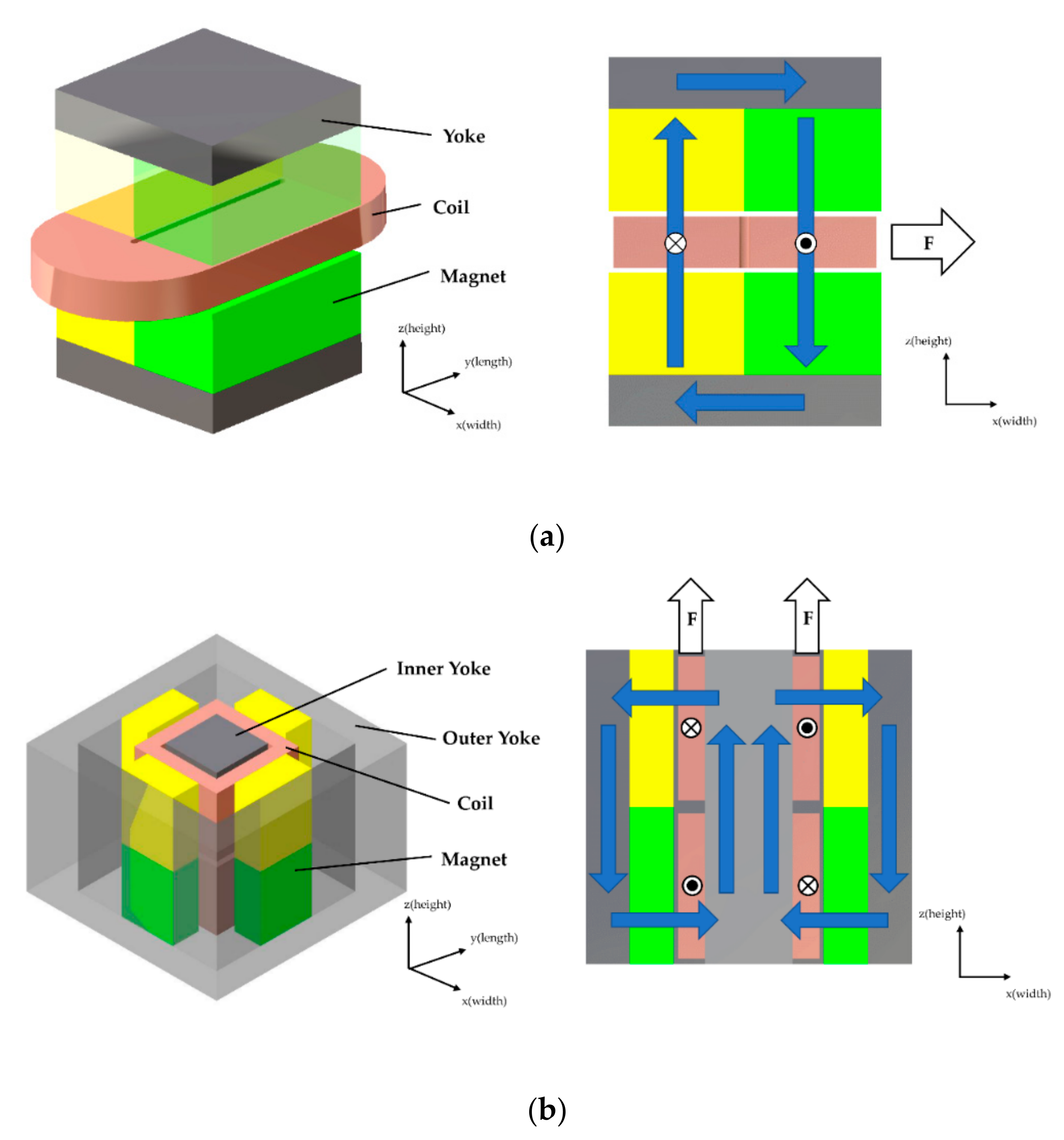
2. Structure of VCMs

A VCM consists of a permanent magnet that generates a magnetic flux, a yoke that concentrates the magnetic flux in an air gap by manipulating the magnetic flux path, and a coil that generates force by flowing current. Figure 1 shows the basic structure of the two types of VCM analyzed in this study.
Figure 1a shows the structure of a typical VCM. Two pairs of magnets are arranged on each side of the coil to form a strong magnetic flux in the perpendicular direction (z) to the air gap, and force is generated in the horizontal direction (x) by the current flowing along the coil in the perpendicular direction (y) to the magnetic flux. Thus, we call this type of VCM “horizontal force voice coil motor” (HVCM). Here, a yoke is attached to the upper and lower sides to concentrate the magnetic flux in the air gap. Figure 1b shows the rectangular type axis-symmetric VCM developed by Choi et al. [17], in which four pairs of magnets are arranged in an external yoke, while an internal yoke that is sufficiently thick to prevent magnetic saturation is positioned in the center. Two upper and lower coils are wrapped around the internal yoke. Here, a magnetic flux is formed in the horizontal direction (x and y) in the air gap between the permanent magnet and the center yoke, and force is generated in the vertical direction (z) as the current flows along the coil in the perpendicular direction (y and x) to the magnetic flux. Thus, we call this type of VCM “vertical force voice coil motor” (VVCM). In this research, how to increase the force of the VCM was studied as a measure for overcoming insufficient force, which is the drawback of general VCMs. The force of the VCM is Lorentz force described by Equation (1), and the magnitude of the force is calculated by Equation (2).
F   = i c o i l ( d   l   × B   ) = i c o i l B d l sin θ  
F   = i c o i l B   d l sin θ
In Equations (1) and (2), i refers to the current, l refers to the length of the coil, B refers to the magnetic flux density in the coil, and θ refers to the angle between the flow direction of the current in the coil and the magnetic flux density. Force vector F can be calculated by integrating a cross product of the infinitesimal length vector multiplied by current and the magnetic flux density in each portion of the coil through the whole coil volume. From Equation (2), it is found that the force of the VCM can be improved by several methods. First, the generated force is proportional to the current in Equation (2). Thus, an increase in force can be obtained in proportion to the increase in the input current, regardless of the VCM’s structure or size. However, an increase in the current incurs increased heat dissipation due to the electric resistance of the coil, thereby inducing a temperature rise in the coil and the surrounding components. Thus, the possible input current can be determined according to the allowable temperature limit of the magnets, coils and others. Since the temperature rise and allowable temperature vary even in the same VCM depending on the operation conditions - such as the cooling method, connection of the VCM to other structure, and the required force trajectory - the effect of an increase in current is excluded from this study. The force can increase when the value of integration of Equation (2) increases. In order to make the sine function term have the maximum value of 1, the flow direction of the current in the coil and the magnetic flux density should be perpendicular, which is implemented by the structure of the magnet and coil in the two types of VCMs, as shown in Figure 1. To increase the integration value in Equation (2), the volume of the coil (i.e. the integration volume) or the magnetic flux density in the volume occupied by the coil should increase. Accordingly, either the number of turns of the coil winding, length, and width should be increased, or a larger magnet should be used. That is, the overall volume of the VCM should be increased. Therefore, this study analyzes a change in force according to the degree of volume change and the volume change method.

3. Analysis

3.1. Design Parameters

As discussed in Section 2, when the volume of the VCM increases, the magnetic flux density increases, or the coil volume that is affected by the magnetic flux increases, expecting the increase in the force generated by the VCM. For a quantitative analysis of force using FEM, the parameters for changing the volume of the HVCM and the VVCM, and their directional shape change model, were established. Figure 2 and Figure 3 show the method of changing their shape in detail, while Table 1 and Table 2 present a detailed description of the parameters. The shape parameters can change from 20% to 200% based on the nominal size.
Figure 2 displays the method of changing the HVCM shape parameters as cross-sectional diagrams. Figure 2a–e corresponds to case (a)–(e), as shown in Table 1. Figure 2a,b refers to cases (a) and (b), where the HVCM volume changes in the x-direction, which is the width direction. Thus, the sizes of both magnets and yokes change in the direction perpendicular to the magnetization direction, and the change in the value is indicated by the change in the magnet’s width, as shown in Table 1. The coil’s width increases and decreases at the same rate as the change in the magnet’s width in case (b), whereas the coil’s width is fixed to the nominal size and each coil bundle is moved to be positioned in the center of each magnet in case (a). This is to consider the case of the largest force occurrence because the magnetic flux density by the permanent magnet is strongest in the point aligned with the center of the magnet. Here, if the magnet width is smaller than the nominal value of the coil width, part of the coil is placed outside the magnetic field of the permanent magnet, which does not generate force. Thus, such a case is excluded from the analysis. As a result, only the range in which the magnet width is larger than the coil width is checked in case (a). Figure 2c shows case (c), where the HVCM volume changes in the y-direction, which is the length direction. Thus, the sizes of both magnet and yoke change in the direction perpendicular to the magnetization direction, and the coil is also interlocked, so its length also increases. If the coil’s length is not interlocked, so that the magnet becomes longer than the coil, force is generated in an unintended direction by the round part of both ends of the coil. Conversely, if the magnet is shorter than the coil, part of the coil may not generate force. Figure 2d,e show cases (d) and (e), where the HVCM volume changes in the z-direction, which is the height direction. In case (d), the magnet height increases, and the coil’s height is fixed to the nominal size. On the other hand, in case (e), the coil’s height increases, and the magnet’s height is fixed to the nominal size. Thus, the parts of the magnet or yoke marked with a dotted line move without any changes in size, maintaining the air gap with the coil.
Figure 3 shows the method of changing the VVCM’s shape parameters as cross-sectional diagrams. Figure 3a–e corresponds to case (a)–(e) as shown in Table 2. Figure 3a–c refer to case (a)–(c), where the VVCM volume changes in the x and y directions, that is, the width direction. In contrast with the HVCM, since the VVCM is symmetrical around the z-axis, the volume increases in the x and y directions simultaneously. For case (a), the size of the four pairs of magnets, whereby each pair is located up and down along the inner surface of the external yoke, change in the magnetization direction. That is, the magnet’s thickness changes, which changes the location and size of the external yoke, thereby changing the overall size of the VVCM in the width direction. In contrast, in case (b), the coil’s thickness changes, and the four pairs of magnets move without any change in their size, maintaining the air gap with the coil. Accordingly, the location and size of the external yoke change, thereby changing the overall size of the VVCM in the width direction. Case (c) is a method in which the widths of both magnet and coil change together. Thus, the coil’s total length increases in case (c)m whereas the number of coil turns increases in case (b). Moreover, the size of the magnet changes in the direction perpendicular to the magnetization direction, in contrast with case (a). Accordingly, the location and size of the external yoke change, thereby changing the overall size of the VVCM in the width direction. Figure 3d,e refer to cases (d) and (e), where the VVCM volume changes in the z-direction, which is the height direction. Thus, the dimension of the magnet changes in the height direction perpendicular to the magnetization direction. However, the coil moves to be positioned in the point aligned with the center of each magnet, without any change in size in case (d), and the dimension changes at the same rate as that of the magnet in case (e). Similarly, to the previous case (b) of the HVCM, when the magnet height is smaller than the coil height, part of the coil is not affected by the magnetic field, which was excluded from the analysis.
Figure 4 shows two extreme cases of HVCM design with the same volume. One in Figure 4a is expanded lengthwise and one in Figure 4b is expanded widthwise while both are keeping the same volume. As noticed from the two extreme cases, it is expected that the volume increase does not guarantee the force increase. The quantitative study by FEM models with the defined design parameters is followed.

3.2. The FEM Model

Based on the design parameters shown in Table 1 and Table 2, three-dimensional simulation models of two types of VCMs were established. For the FEM analysis, Maxwell V14.0 (Ansys, USA) was used. The current density in the coil cross-section was set to be constant to present the increase of coil turns according to the increase of the coil cross-sectional area. In addition, all the analyses were performed by designating an N-45 grade NdFeB magnet, and its characteristics are shown in Table 3. Figure 5 shows an example of a meshed model of two VCMs. The force applied to the coil and the magnetic flux density at the coil were calculated by the analysis. The analysis region was set to have 1000% offset size of the analyzed VCM model, and the medium was air. Each analysis was terminated when the energy error converged to less than 0.1%, and the maximum number of iterations was limited to 30.

3.3. Results

Figure 6a shows the change in force according to the change in size of the HVCM. In all shape change methods, as the VCM volume increases, the force increases. However, there is a difference in force change according to the direction of the volume change. The increase in force in case (a)–(c), in which the HVCM increases in the horizontal direction, i.e., in the width and lengthwise direction, is significantly larger than that of cases (d) and (e), in which the HVCM increases in the height direction, i.e., the vertical direction. In particular, the increase in force in cases (b) and (c), where the volume of both coil and magnet increases, is more effective than case (a), where only the magnet’s volume increases. Case (a) is somewhat limited in terms of increasing the force as it has a saturation form after a certain level of increase. This directional effect of an increase in force can be explained more clearly through the change in the mean magnetic flux density according to the increase in the HVCM volume, as shown in Figure 6b. The increase in the magnetic flux density in case (a)–(c), in which the HVCM increases in the horizontal direction, that is, the width and lengthwise direction, is also significantly larger than that of cases (d) and (e), in which the HVCM increases in the height direction, i.e., in the vertical direction. Here, the increase in the mean magnetic flux density according to the increase in the magnet size is the largest in case (a), and smaller in cases (b) and (c). As presented in Equation (2), the force of the VCM is affected by increases in both magnetic flux density and coil length, but the increase in coil volume is more effective than the increase in magnetic flux density, as shown in Figure 6a,b. In particular, the magnetic flux density increases in line with the increase in the magnet’s volume, but it becomes saturated beyond a certain level. Thus, when a large-scale HVCM is available, an increase in coil volume leads to a substantial increase in force, and an increase in a magnet size raises the magnetic flux, which only plays a role in maintaining the magnetic flux density at a certain level even if the coil’s volume increases. This trend is also revealed in cases (d) and (e). In case (d), the magnetic flux density increases to some extent, and is then saturated as the magnet’s height increases, whereas in case (e), the magnetic flux density decreases as the distance between the magnets increases. Nonetheless, the force increases more in case (e) than in case (d), which indicates that the effect of a change in the coil volume is more significant than the effect of a change in the magnet volume.
Finally, force change to volume change was presented regarding the change in the shape parameters to verify the efficiency of the increase in the volume for the increase in the force of the HVCM. The absolute value of the volume change was used to represent the increase and decrease in force using signs. As shown in Figure 6c, case (c) is most noticeable. That is, the increase in volume in the lengthwise directions of the magnet and coil is the most efficient method of increasing the force. As Figure 6a verified that the effect of the increase in volume in the height direction (cases (d) and (e)) was limited, Figure 6c also shows that the effect by height increase diminishes according to volume increase. Thus, the height of the coil and magnet is fixed to an appropriate value rather than increasing it, and the volume in the direction perpendicular to the height is desirable in order to increase the force of the HVCM. One more noticeable result is the case (b). When the volume increases in the width direction, the number of coil turns increases, thereby increasing the part of the coil that is not involved in the generation of force (as shown in Figure 7). It can cause distortion of the coil shape overall and generation of Lorentz force in the undesired direction. Thus, it is necessary to maintain a width to length ratio below a certain value. Moreover, the difference between the results of the case (a) and (b) tells that the increase in the widths of the magnet and coil by interlocking them (cases (b)) is more efficient than increasing the width of the magnet only (case (a)). Thus, it is preferable to fix the magnet width to be no larger than necessary to motion compared to the coil width when designing the HVCM.
Figure 8a shows the change in force according to the change in the VVCM size. Except for case (b), all cases showed that the generated force increased as the volume of the VVCM increased. The trend of increase in force differed depending on which part and direction of the VVCM increased in volume. The increase in force was larger in cases (c) and (e) of the VVCM, where the volume of both magnet and coil increased than in cases (a) and (d), where the volume of either the magnet or coil only increased. In addition, the increase in force was larger in case (e) than in case (c), and in case (d) than in case (a), respectively. In other words, force is larger in the cases where the volume increased in the vertical height direction than the cases where the volume increased in the horizontal width direction. In relation to the change in the mean magnetic flux density according to the increase in the VVCM volume, as shown in Figure 8b, only case (b) showed a rapid reduction of the magnetic flux density. Since the size of the magnet remained the same, while the coil’s volume increased, thereby increasing the air gap. Thus, the magnetic flux density decreased, accordingly the force decreased, as shown in Figure 8a, despite the increase in the coil volume. In both cases (a) and (c), the volume increased in the horizontal width direction. The magnetic flux density increased in case (c), where the magnet dimension increased in the direction perpendicular to the magnetization direction, more than in case (a), where the magnet dimension increased in the direction parallel to the magnetization direction. Furthermore, the volume of coil also increased in case (c), thereby further increasing the force significantly. In both cases (d) and (e), the volume increased in the vertical height direction. Evidently, case (d), in which the magnet size increased but the coil volume did not change, showed a higher magnetic flux density. However, the increase in force was larger in case (e), i.e., the same as the HVCM result, which indicates that the change in the coil volume influenced more in the change of force in the VVCM as well.
Next, Figure 8c shows force change to volume change regarding the change in the shape parameters. The absolute value of the volume change was used to represent the increase and decrease in force using signs. The force is efficiently increased when the respective size of the coil and magnet increased simultaneously in width direction (case (c)) and height direction (cased (e)). Note that the value of case (c) is higher than the value of case (e), which contrasted with the results of force. This is because the increase in the VVCM’s overall volume according to the increase in the magnet’s width in case (c) was significantly smaller than the increase in the VVCM’s overall volume according to the increase in the magnet’s height in case (e). On the other hand, although case (d), in which only the magnet’s height increased, could obtain an increase in force, the force increase with respect to volume increase was diminished demonstrating significantly low efficiency of the volume increase. Therefore, when designing the VVCM, it is recommended that the height of the magnet is not set larger than necessary compared to the height of the coil. In case (a), a small change of volume affects largely on force change, but its effect rapidly diminishes. As a result, the generated force barely changes as shown in Figure 8a. Thus, selecting the proper thickness of the magnet and coil followed by increasing the VVCM volume in the width and height directions (case (c) and (e)) was found to be effective in increasing the force of the VVCM.
In summary, with the increase in the size of the HVCM and the VVCM, the magnetic flux density and coil volume increase, which in turn increases the force. In particular, the increase in the coil volume significantly influenced the increase in force, and the increase in the magnet volume raised the magnetic flux, thereby maintaining the magnetic flux density at a similar rate even when the coil’s volume increased. Thus, the magnet size must increase in link with the coil size. For the HVCM, only the method which increases both the size of the magnet and the coil in the lengthwise directions is found to be valid in terms of the manufacturability and the efficiency of the increase in force. Here, an increase in the coil volume should lead to an increase in the total length. For the VVCM, an improvement of force can be attempted by increasing the volume in the vertical or horizontal direction. Here, an increase in the coil volume in the vertical direction should lead to an increase in the number of accumulated turns by heightening the coil height, while an increase in the horizontal direction should lead to an increase in the total length by widening the coil width rather than the thickness.

4. VCM Designs for a Maglev Positioning Device

Based on the results of the analysis presented in Section 3, two types of VCMs were designed for a precision maglev precision positioning device. Since a maglev device performs positioning while floating in the air and a VCM generates uni-directional force, for six-DOF motion control, it requires more than 6 VCMs. In this paper, eight VCMs were arranged as shown in Figure 9a by considering the symmetry. VCMs for a vertical motion were arranged at the four vertices, and VCMs for a horizontal motion were arranged along the four edges. Utilizing the VCMs at vertices, the maglev positioning device can achieve the out-of-plane motion, that is, motion in the z, θx, and θy directions. Similarly, utilizing the VCMs at edges, the maglev positioning device can achieve the in-plane motion, that is, motion in the x, y, and θz directions. In the maglev device, not only a space for VCMs but also a space in which to arrange the displacement sensor and the mechanical stopper for homing was also needed, as shown in Figure 9a,b. The mover of the maglev positioning device has a size of 250 mm × 250 mm × 40 mm. Accordingly, the given space for VCMs is limited as presented in Table 4. Because of this space arrangement and assembly, a type of VVCM that was suitable to be increased in the vertical direction was selected for a vertical motion, while a type of HVCM that was suitable to increase in the length direction was selected for a horizontal motion.
The design of the VCM started with setting the outer size. Each VCM was set so that its outer size occupies the whole given volume to generate the maximum force. The gap between the coil and the magnet and the difference in width between the coil and magnet was set to 1mm in consideration of the motion range of the maglev positioning device. In the case of HVCM, the maximum force was obtained through the FEM analysis by adjusting the height of the coil and magnet in units of 1 mm through. In the case of VVCM, the maximum force was obtained through the FEM analysis by adjusting the thickness of the coil and magnet in units of 1 mm through FEM analysis. The final design parameters and specifications are shown in Table 4 and Figure 10. In addition to this, in order to show the effectiveness of the study, the force maximization of VVCM and HVCM was carried out assuming that the spaces given to each were changed. The comparison of the results is presented in Table 5. As can be seen from the Table 5, the results are very different depending on which type of VCM is optimized for the same volume of space. The incorrectly selected VCM only shows a force constant of about 60%. This confirms that the efficiency of increasing the force according to the volume expansion of the VCM is different for each direction of the volume expansion.

5. Conclusions

In this paper, two types of VCMs were selected and a shape change model was established. One of them had a typical structure and comprised a coil positioned between two pairs of magnets. The other had a rectangular shape with an external yoke consisting of four pairs of magnets and a rectangular inner yoke. An efficient method of improving the force was analyzed through the increase in VCM volume by employing the shape change model analysis of the two selected types of VCMs.
  • An increase in force can be attempted by increasing the VCM volume. However, the efficiency of an increase in force differs depending on the method and direction of the volume increase and the type of VCM.
  • The HVCM’s force increased significantly when the volume increased in the width and the length direction. However, the most efficient method of enhancing force consisted of increasing the volume in the lengthwise direction while maintaining a certain ratio between the width and length in consideration of the coil fabrication.
  • The VVCM’s force increased significantly when the volume increased in the width and height directions. The total length of the coil increases when the VVCM width increases, and the number of coil turns increases when the VVCM height increases.
  • Two VCMs could efficiently increase the volume with appropriate direction, after selecting an appropriate thickness for the magnet and coil and setting the magnet’s size to be no larger than that of the coil.
Based on the results of the VCM analysis, two types of VCMs were designed. The maglev device should always maintain a levitation force that corresponds to its own weight for levitation of the moving component, as well as generating an inertial force, in order to achieve a fast motion. Accordingly, the HVCM and VVCM were designed to have high force for the given space limitation.
In this paper, we analyzed the force increase according to the VCM volume increase, and it is expected that the data presented here can be useful when designing the VCM. It can provide a starting point for the design, such as what type of VCM to select according to the constraints such as a given space, and how much the initial values of magnets and coils should be. It can also be used as a reference when deciding in which direction the size should be increased during design refinement.

Author Contributions

Formal analysis and original draft preparation, J.-Y.K.; Conceptualization, methodology and software, and review and editing, D.A. All authors have read and agreed to the published version of the manuscript.

Funding

This research was supported by the National Research Foundation of Korea (NRF) grant funded by the Korea government (MSIT) (No. NRF-2019R1G1A1099736).

Conflicts of Interest

The authors declare no conflict of interest.

References

  1. Gao, W.; Arai, Y.; Shibuya, A.; Kiyono, S.; Park, C.H. Measurement of multi-degree-of-freedom error motions of a precision linear air-bearing stage. Precis. Eng. 2006, 30, 96–103. [Google Scholar] [CrossRef]
  2. Ro, S.K.; Kim, S.; Kwak, Y.; Park, C.H. A linear air bearing stage with active magnetic preloads for ultraprecise. Precis. Eng. 2010, 34, 186–194. [Google Scholar] [CrossRef]
  3. Ro, S.K.; Park, J.K. A compact ultra-precision air bearing stage with 3-DOF planar motions using electromagnetic motors. Int. J. Precis. Eng. Manuf. 2011, 12, 115–119. [Google Scholar] [CrossRef]
  4. Peijnenburg, A.T.A.; Vermeulen, J.P.M.; van Eijk Ro, J. Magnetic levitation systems compared to conventional bearing systems. Microelectron. Eng. 2006, 83, 1372–1375. [Google Scholar] [CrossRef]
  5. Kim, W.J.; Trumper, D.L. High-precision magnetic levitation stage for photolithography. Precis. Eng. 1998, 22, 66–77. [Google Scholar] [CrossRef]
  6. Jansen, J.W.; van Lierop, C.M.M.; Lomonova, E.A.; Vandenput, A.J. Magnetically levitated planar actuator with moving magnets. IEEE Trans. Ind. Appl. 2008, 44, 1108–1115. [Google Scholar] [CrossRef] [Green Version]
  7. Zhu, H.; Teo, T.J.; Pang, C.K. Design and modeling of a six-degree-of-freedom magnetically levitated positioner using square coils and 1-D halbach arrays. IEEE Trans. Ind. Electron. 2017, 64, 440–450. [Google Scholar] [CrossRef]
  8. Hollis, R.L.; Salcudean, S.E.; Allan, A.P. A six-degree-of-freedom magnetically levitated variable compliance fine-motion wrist: Design, modeling, and control. IEEE Trans. Robot. Autom. 1991, 7, 320–332. [Google Scholar] [CrossRef]
  9. Verma, S.; Shakir, H.; Kim, W.J. Novel Electromagnetic Actuation Scheme for Multiaxis Nanopositioning. IEEE Trans. Magn. 2006, 42, 2052–2062. [Google Scholar] [CrossRef]
  10. Kim, W.J.; Verma, S.; Shakir, H. Design and precision construction of novel magnetic-levitation-based multi-axis nanoscale positioning systems. Precis. Eng. 2007, 31, 337–350. [Google Scholar] [CrossRef]
  11. Zhang, Z.; Menq, C. Six-Axis Magnetic Levitation and Motion Control. Ieee Trans. Robot. 2007, 23, 196–205. [Google Scholar] [CrossRef]
  12. Ahn, D.; Kim, H.; Choi, K.; Choi, Y.M.; Lim, J.Y. Design process of square column-shaped voice coil motor design for magnetic levitation stage. Int. J. Appl. Electromagn. Mech. 2019, 1, 1–24. [Google Scholar] [CrossRef]
  13. Choi, Y.M.; Gweon, D.G. A High-precision dual-servo stage using halbach linear active magnetic bearings. IEEE/ASME Trans. Mechatron. 2011, 16, 925–931. [Google Scholar] [CrossRef]
  14. Kim, M.; Jeong, J.H.; Kim, H.; Gweon, D.G. A six-degree-of-freedom magnetic levitation fine stage for a high-precision and high-acceleration dual-servo stage. Smart Mater. Struct. 2015, 24, 105022. [Google Scholar] [CrossRef]
  15. John, S.; Sirohi, J.; Wang, G.; Wereley, N.M. Comparison of Piezoelectric, Magnetostrictive, and Electrostrictive Hybrid Hydraulic actuators. J. Intell. Mater. Syst. Struct. 2007, 18, 1035–1048. [Google Scholar] [CrossRef]
  16. Vrijsen, N.H.; Jansen, J.W.; Lomonova, E.A. Comparison of linear voice coil and reluctance actuators for high-precision applications. In Proceedings of the 14th International Power Electronics and Motion Control Conference, Ohrid, North Macedonia, 6–8 September 2010; Volume 22, pp. 29–36. [Google Scholar]
  17. Choi, Y.M.; Ahn, D.; Gweon, D.G.; Lee, M.G. Design of a rectangular-type voice coil actuator for frame vibration compensation. J. Magn. 2016, 21, 348–355. [Google Scholar] [CrossRef] [Green Version]
  18. Lee, J.; Wang, S. Topological shape optimization of permanent magnet in voice coil motor using level set method. IEEE Trans. Magn. 2012, 48, 931–934. [Google Scholar] [CrossRef]
  19. Choi, Y.M.; Lee, M.G.; Gweon, D.G.; Jeong, J. A new magnetic bearing using Halbach magnet arrays for a magnetic levitation stage. Rev. Sci. Instrum. 2009, 80, 45106. [Google Scholar]
  20. Kim, M.H.; Kim, H.Y.; Kim, H.C.; Ahn, D.; Gweon, D. Design and Control of a 6-DOF Active Vibration Isolation System Using a Halbach Magnet Array. IEEE/ASME Trans. Mechatron. 2016, 21, 2185–2196. [Google Scholar] [CrossRef]
  21. Dong, L.; Chen, J.; Zhang, C.; Wu, D.; Yu, G.; Liu, Q. Design and comparison of three-type VCMs for nano-positioning system. In Proceedings of the 2016 IEEE 11th Conference on Industrial Electronics and Applications, Hefei, China, 5–7 June 2016. [Google Scholar]
  22. Janssen, J.L.G.; Paulides, J.J.H.; Encica, L.; Lomonova, E. High-performance moving-coil actuators with double-sided PM arrays: A design comparison. In Proceedings of the International Conference on Electrical Machines and Systems, Incheon, Korea, 10–13 October 2010. [Google Scholar]
Figure 1. (a) Structure of a typical voice coil motor (VCM) with double-sided magnets, (b) Structure of a square column type VCM.
Actuators 09 00133 g001
Figure 2. Variations of the horizontal force voice coil motor (HVCM)’s structure according to changes in the design parameters: (a) case (a), change of magnet width; (b) case (b), change of VCM width; (c) case (c) change of VCM length; (d) case (d) change of magnet height; (e) case (e) change of coil height.
Actuators 09 00133 g002aActuators 09 00133 g002b
Figure 3. Variations of the vertical force voice coil motor (VVCM)’s structure according to changes in the design parameters: (a) case (a), change of magnet thickness; (b) case (b), change of coil thickness; (c) case (c), change of VCM width; (d) case (d) change of magnet height; (e) case (e) change of VCM height.
Actuators 09 00133 g003aActuators 09 00133 g003b
Figure 4. Extreme variations of HVCM with the same volume, (a) Lengthwise expansion, (b) Widthwise expansion.
Actuators 09 00133 g004
Figure 5. (a) Meshed simulation model of HVCM with nominal dimensions, (b) Meshed simulation model of VVCM with nominal dimensions.
Actuators 09 00133 g005
Figure 6. Results of analysis of the HVCM, (a) Force, (b) Average magnetic flux density, (c) force increase per volume increase.
Actuators 09 00133 g006aActuators 09 00133 g006b
Figure 7. Usable part of VCM coils for force generation, an example of normal winding (top) and an example of abnormally enlarged winding in the width direction (bottom).
Actuators 09 00133 g007
Figure 8. Results of analysis of the VVCM, (a) Force, (b) Average magnetic flux density, (c) force density.
Actuators 09 00133 g008
Figure 9. (a) Placement of the VCMs on the mover of the maglev device (inverted in the picture), (b) Placement of the displacement sensors and a mechanical stopper for homing.
Actuators 09 00133 g009
Figure 10. The optimized design parameters (a) HVCM, (b) VVCM.
Actuators 09 00133 g010
Table 1. Design Parameters of the HVCM.
Expansion DirectionCaseParametersDescriptionNormalized Dimension (mm)Variation (mm)
x(width)amwMagnet width5252–104
bcwCoil width5010–100
mwMagnet width5210.4–104
y(length)cclCoil length5010–100
mlMagnet length5010–100
z(height)dmhMagnet height204–40
echCoil height204–40
Table 2. Design Parameters of the VVCM.
Expansion DirectionCaseParametersDescriptionNormalized Dimension (mm)Variation (mm)
x, y(width)amtMagnet thickness204–40
bctCoil thickness204–40
cmwMagnet width204–40
cwCoil width204–40
z(height)dmhMagnet height5252–104
echCoil height244–49
mhMagnet height5252–104
Table 3. Properties of the NdFeB magnet.
GradeRemanence (T)Coercive Force (kA/m)
N-45M1.35876
Table 4. Space limitation and specifications of the fabricated HVCM and VVCM.
HVCMVVCM
Given space for VCM design (mm × mm × mm)90 × 50 × 4055 × 55 × 40
Force constant (N/A)17.7119.31
Electrical resistance (Ω)4.502.73
Coil diameter without sheath (mm)0.50.5
Number of coil turns368420
Moving mass (g)471530
Table 5. Comparison of force constant for each optimized design result.
Horizontal Force GenerationVertical Force Generation
Given Space for VCM Design (mm × mm × mm)90 × 50 × 4055 × 55 × 40
HVCM (N/A)17.715.98
VVCM (N/A)10.239.65
Publisher’s Note: MDPI stays neutral with regard to jurisdictional claims in published maps and institutional affiliations.

