Improvement of Comfort in Suspension Seats with a Pneumatic Negative Stiffness System


Abstract
1. Introduction
2. Vehicle and Seat Suspension Model
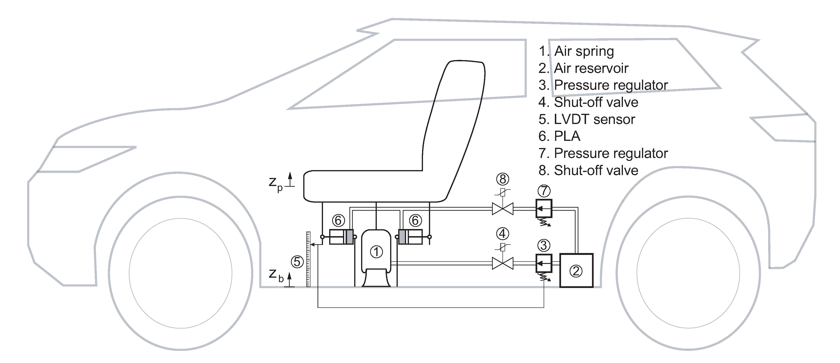
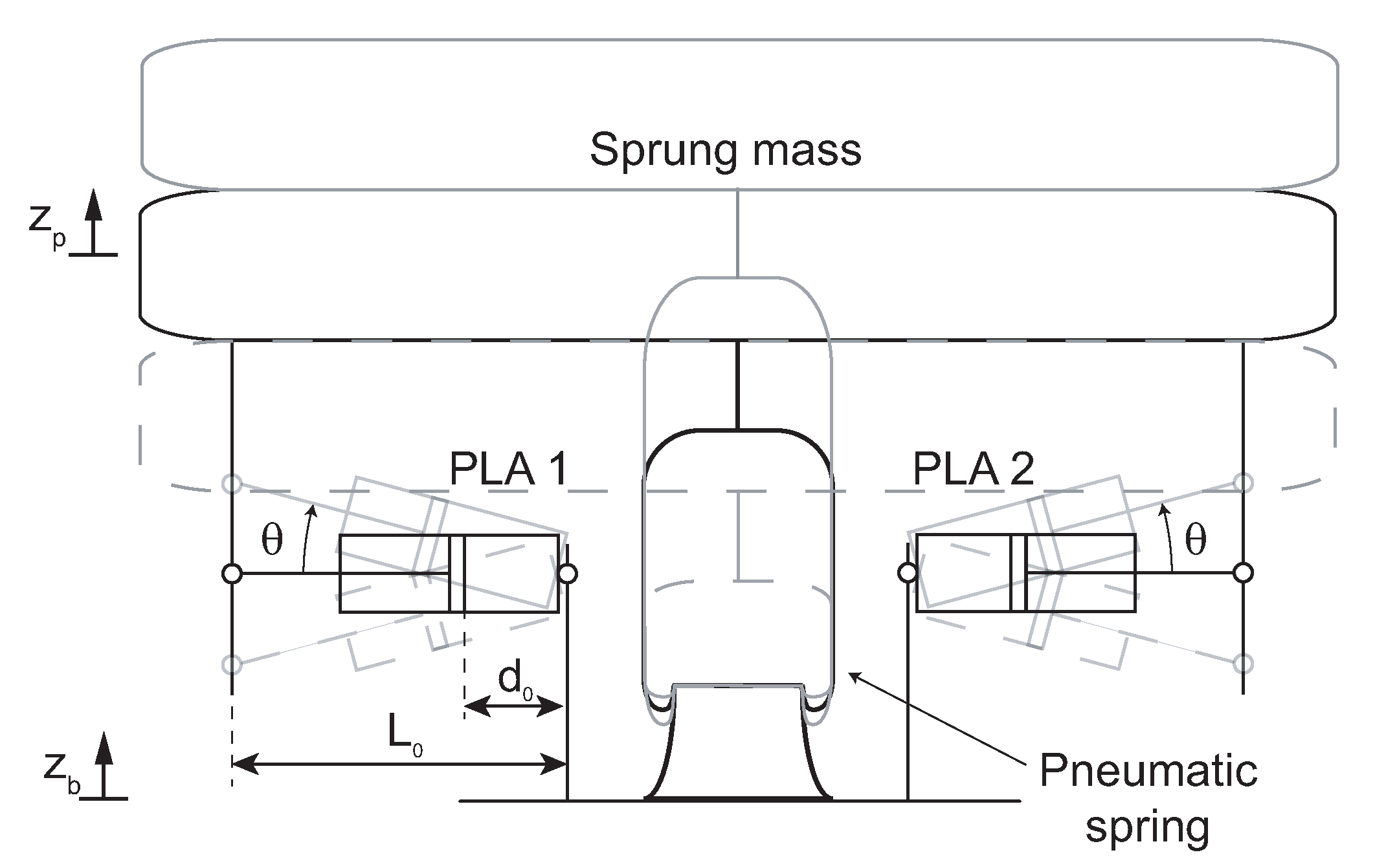
2.1. Seat Suspension Model
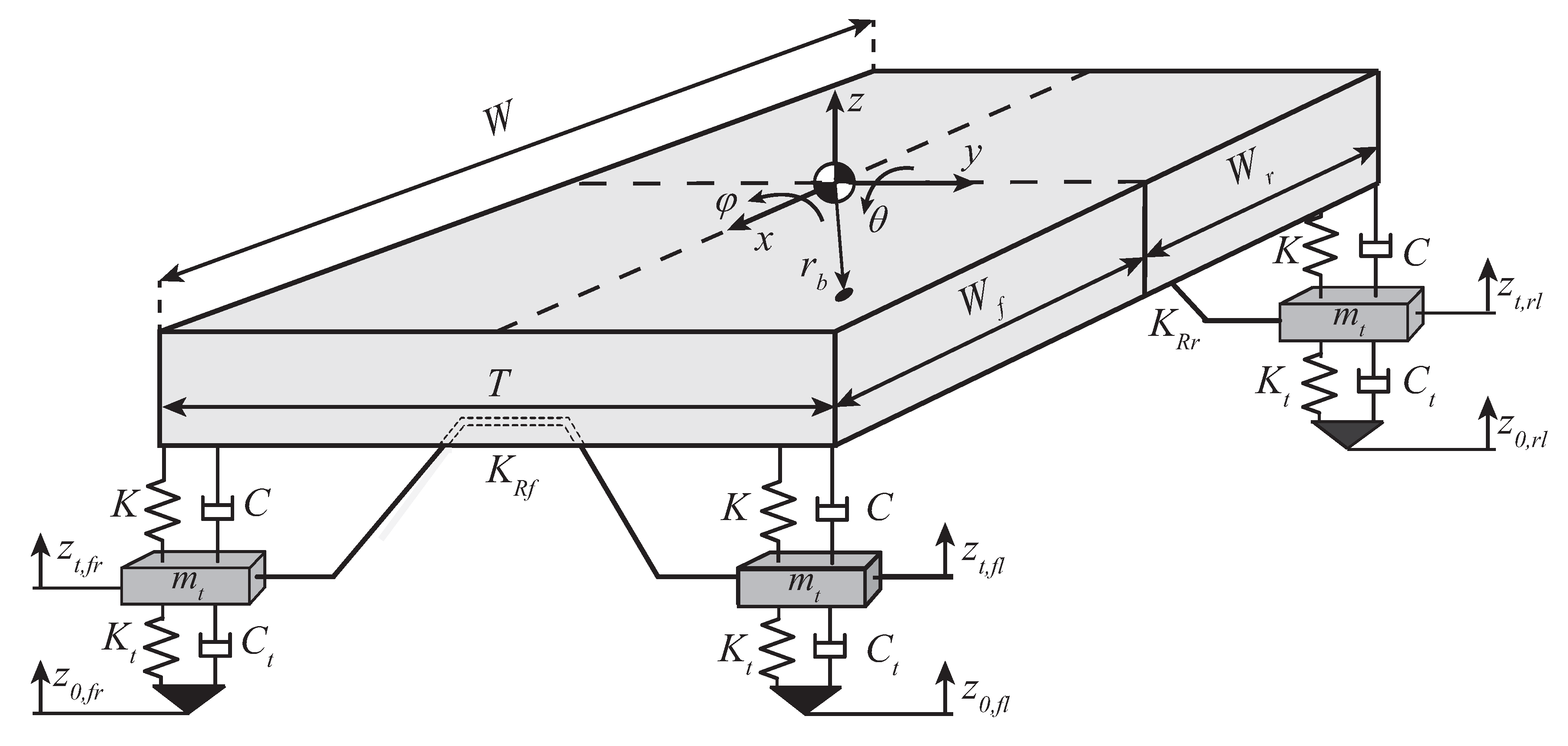
2.2. Vehicle Model
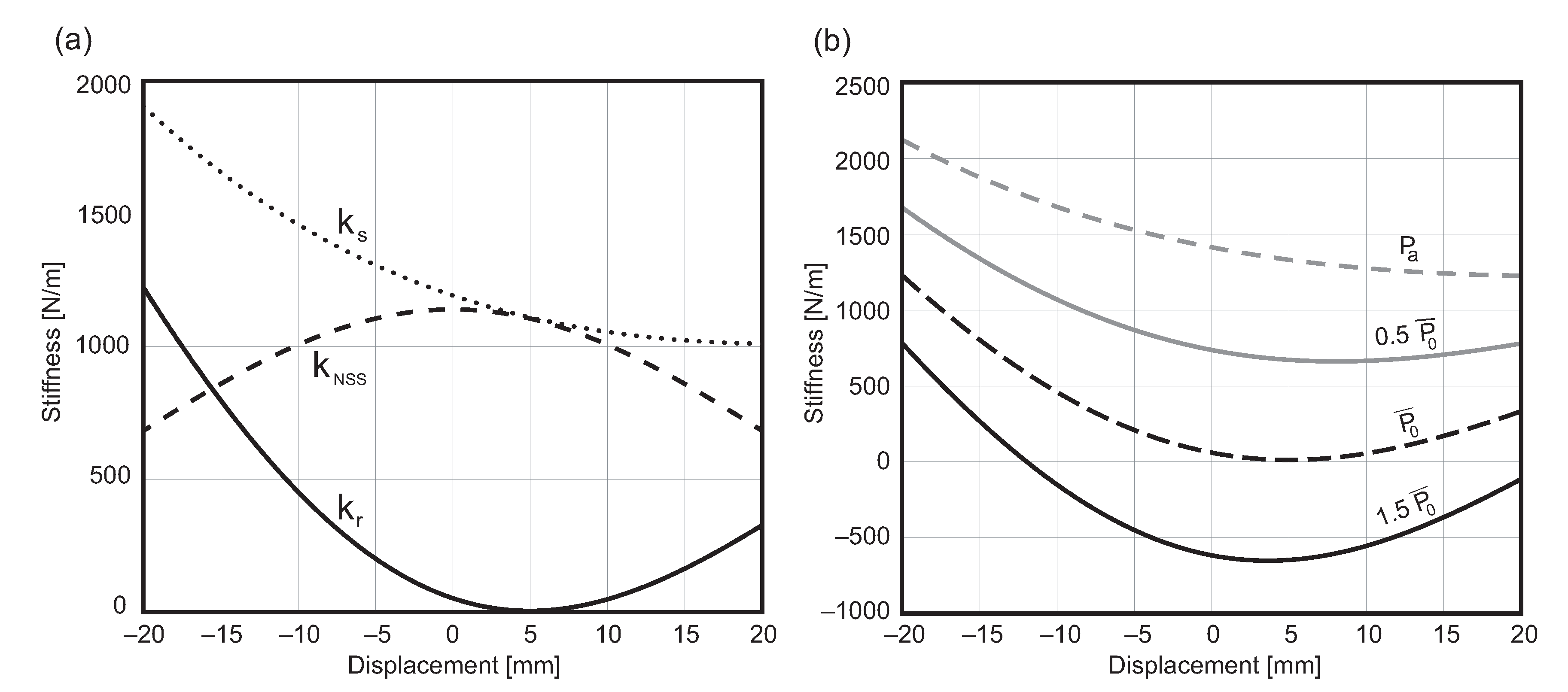
3. Optimal NSS Stiffness
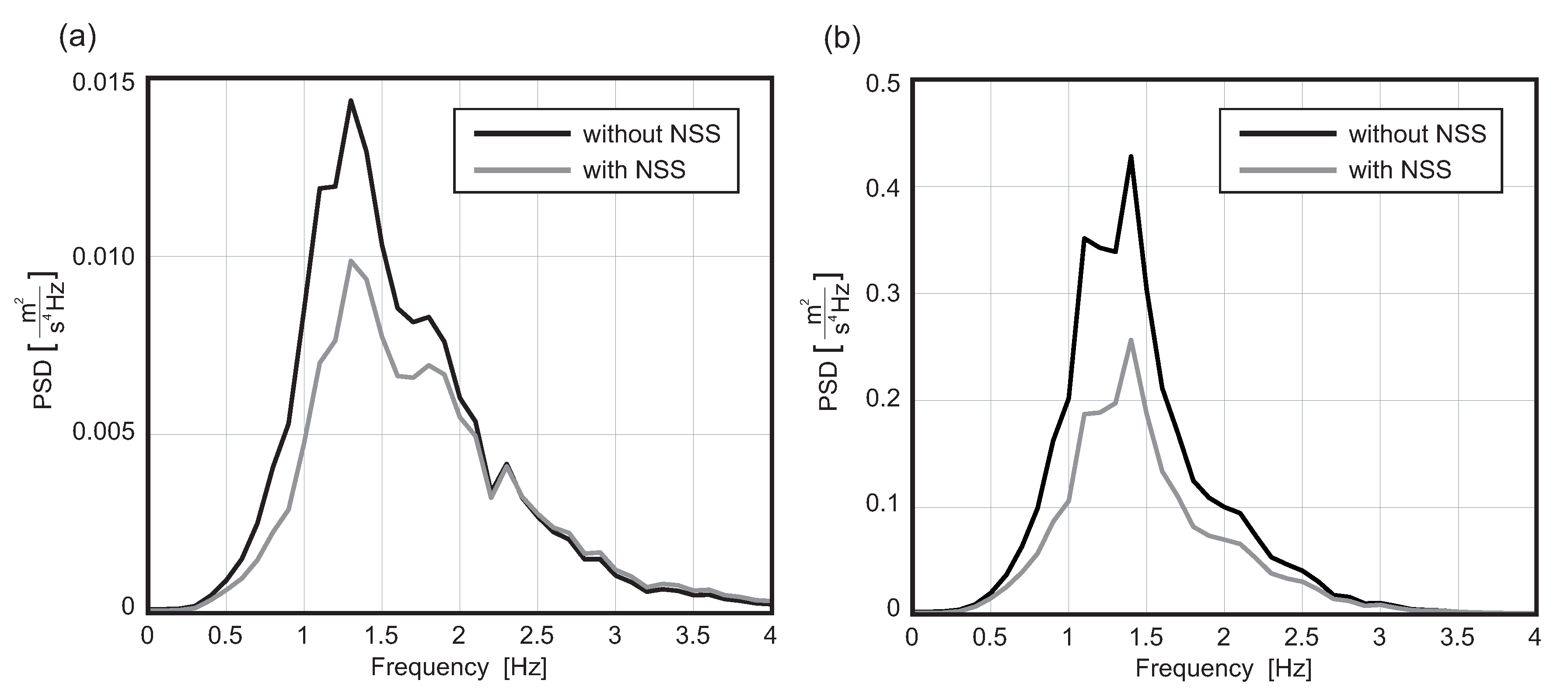
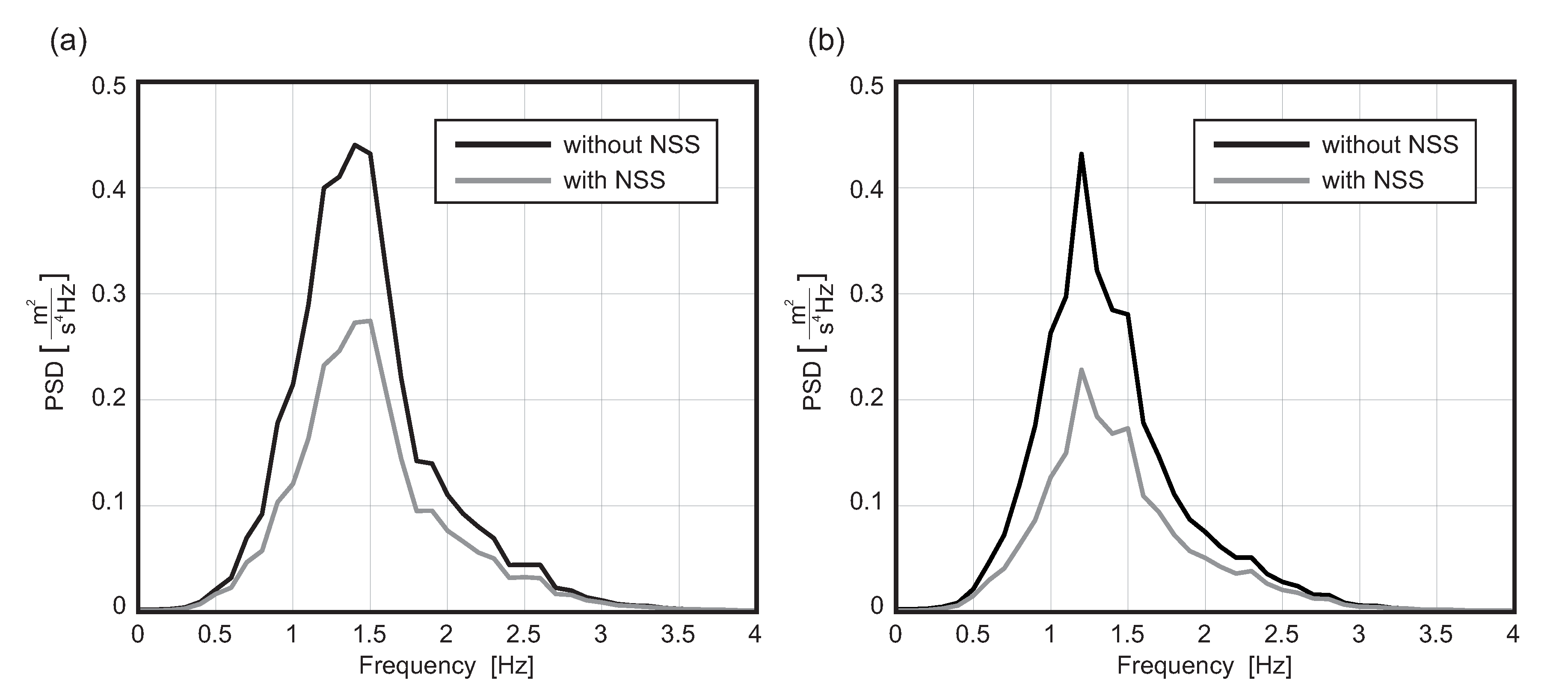
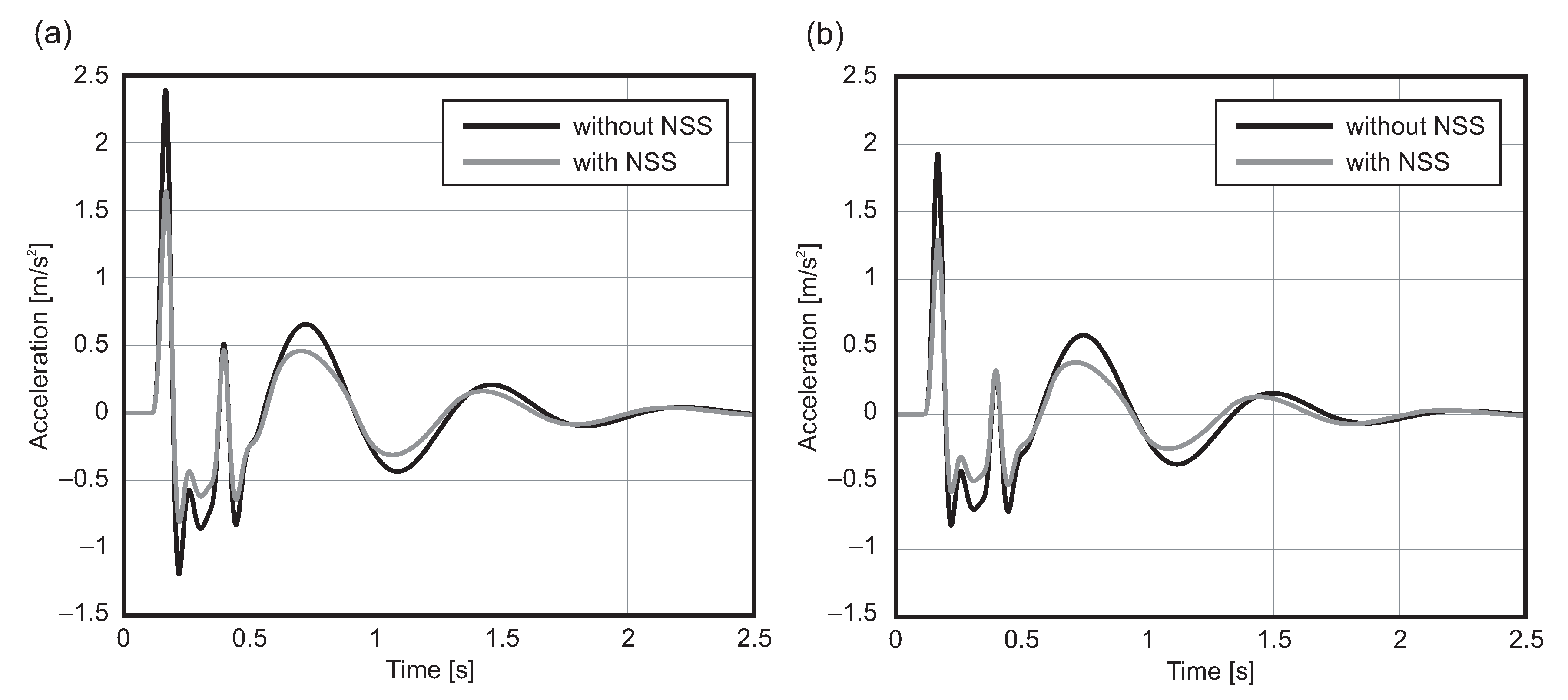
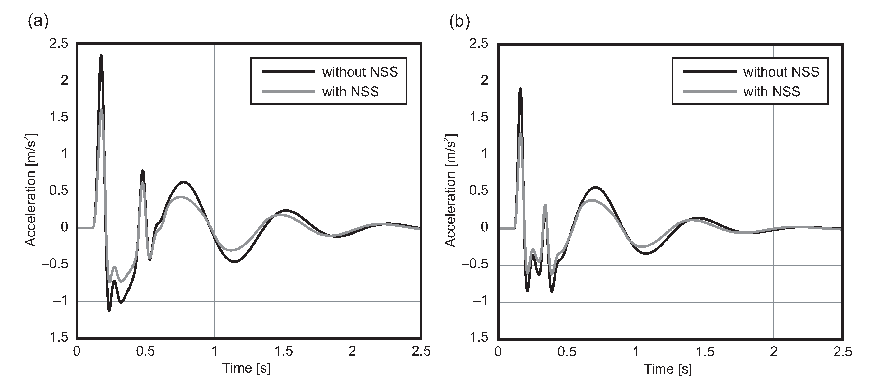
4. Numerical Simulations
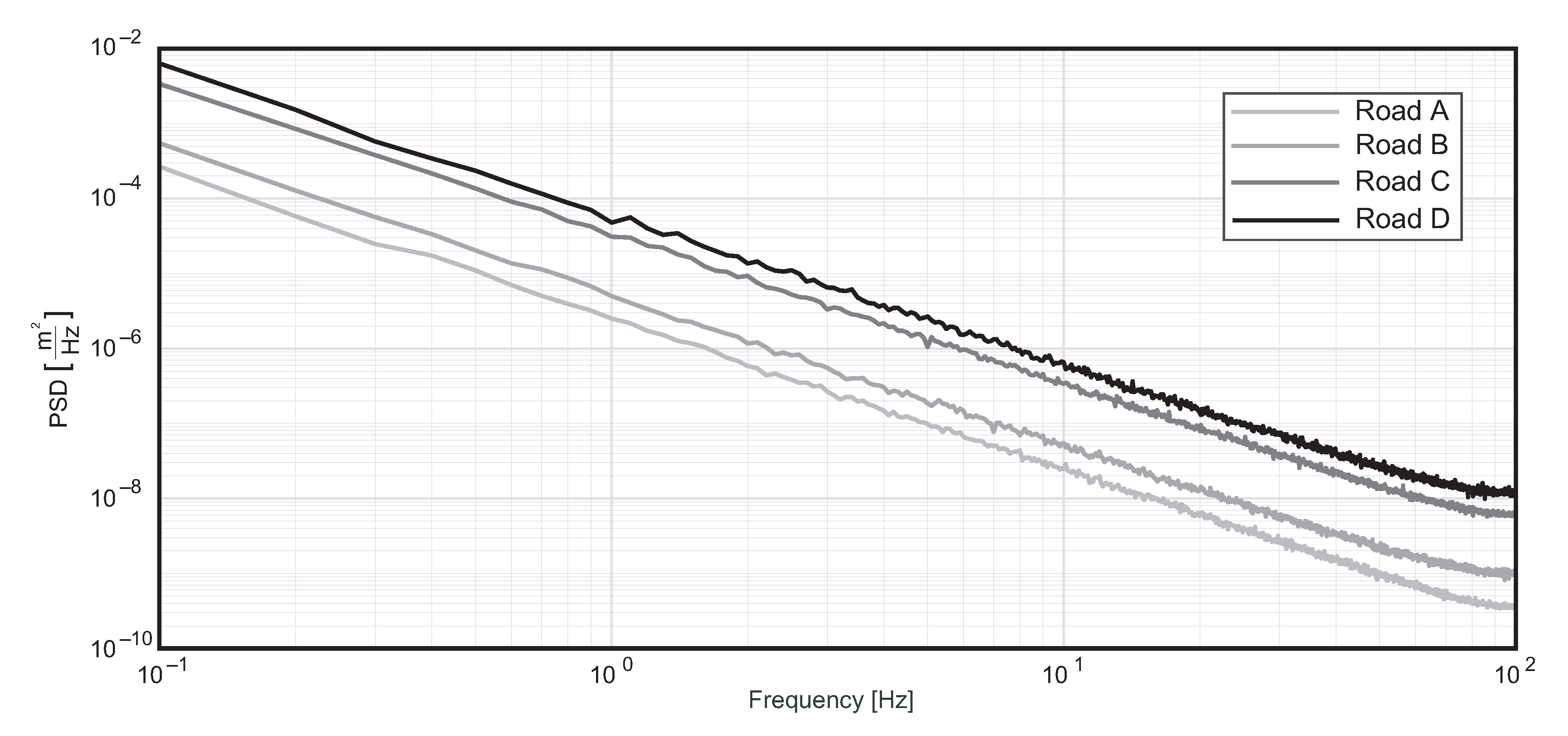
4.1. Road Profile
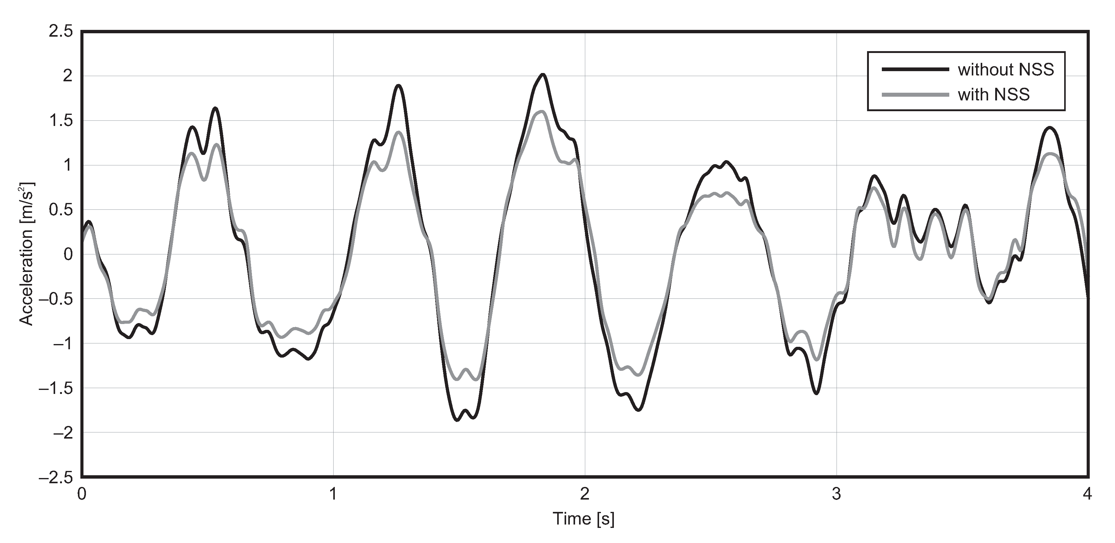
4.2. Speed Bump
5. Conclusions
Author Contributions
Funding
Conflicts of Interest
Abbreviations
| NSS | Negative Stiffness System |
| PLA | Pneumatic Linear Actuator |
| MR | Magnetorheological |
| LVDT | Linear Variable Differential Transformer |
| PSD | Power Spectral Density |
References
- Corbridge, C.; Griffin, M.J. Vibration and comfort: Vertical and lateral motion in the range 0.5 to 5.0 Hz. Ergonomics 1986, 29, 249–272. [Google Scholar] [CrossRef]
- Griffin, M.J. Handbook of Human Vibration; Academic Press Limited: London, UK, 1990. [Google Scholar]
- Mansfield, N.J.; Griffin, M.J. Comparison of biodynamic responses in standing and seated human bodies. J. Sound Vib. 2000, 238, 691–704. [Google Scholar]
- Matsumoto, Y.; Griffin, M.J. Dynamic response of the standing human body exposed to vertical vibration: Influence of posture and vibration magnitude. J. Sound Vib. 1998, 212, 81–94. [Google Scholar] [CrossRef]
- International Standard Organization. ISO-2631-1 Guide for the Evaluation of Human Exposure to Whole-Body Vibration, Part 1: General Requirements; International Standard Organization: Geneva, Switzerland, 2010. [Google Scholar]
- European Standards. EN-12299 Railway Applications. Ride Comfort for Passengers. Measurement and Evaluation; European Standards: Krimicka, Czech Republic, 2009. [Google Scholar]
- Maciejewski, I.; Meyer, L.; Krzyzynski, T. Modelling and multi-criteria optimisation of passive seat suspension vibro-isolating properties. J. Sound Vib. 2009, 324, 520–538. [Google Scholar] [CrossRef]
- Maciejewski, I.; Kiczkowiak, T.; Krzyzynski, T. Application of the Pareto-optimal approach for selecting dynamic characteristics of seat suspension systems. Veh. Syst. Dyn. 2011, 49, 1929–1950. [Google Scholar] [CrossRef]
- Wan, Y.; Schimmels, J.M. Optimal Seat Suspension Design Based on Minimum “Simulated Subjective Response”. J. Biomech. Eng. 1997, 119, 409–416. [Google Scholar] [CrossRef]
- Wan, Y.; Schimmels, J.M. Improved vibration isolation seat suspension designs based on position-dependent nonlinear stiffness and damping characteristics. J. Dyn. Syst. Meas. Control 2003, 125, 330–338. [Google Scholar] [CrossRef]
- Bouazara, M.; Richard, M.J.; Rakheja, S. Safety and comfort analysis of a 3-D vehicle model with optimal non-linear active seat suspension. J. Terramech. 2006, 43, 97–118. [Google Scholar] [CrossRef]
- Abbas, W.; Emam, A.; Badran, S.; Shebl, M.; Abouelatta, O. Optimal seat suspension design for a half-car with driver model using genetic algorithm. Intell. Control Autom. 2013, 4, 199–205. [Google Scholar] [CrossRef]
- Hostens, I.; Deprez, K.; Ramon, H. An improved design of air suspension for seats of mobile agricultural machines. J. Sound Vib. 2004, 276, 141–156. [Google Scholar] [CrossRef]
- Shimogo, T.; Oshinoya, Y.; Shinjyo, H. Active Suspension of Truck Seat. Trans. Jpn. Soc. Mech. Eng. Ser. C 1996, 62, 3132–3138. [Google Scholar] [CrossRef][Green Version]
- Stein, G.J. A Driver’s Seat with Active Suspension of Electropneumatic Type. J. Vib. Acoust. 1997, 119, 230–235. [Google Scholar] [CrossRef]
- Choi, S.B.; Choi, J.H.; Lee, Y.S.; Han, M.S. Vibration Control of an ER Seat Suspension for a Commercial Vehicle. J. Dyn. Syst. Meas. Control 2003, 125, 60–68. [Google Scholar] [CrossRef]
- Guclu, R. Fuzzy Logic Control of Seat Vibrations of a Non-Linear Full Vehicle Model. Nonlinear Dyn. 2005, 40, 21–34. [Google Scholar] [CrossRef]
- Du, H.; Li, W.; Zhang, N. Semi-active variable stiffness vibration control of vehicle seat suspension using an MR elastomer isolator. Smart Mater. Struct. 2011, 20, 105003–105010. [Google Scholar] [CrossRef]
- Phu, D.X.; Choi, S.M.; Choi, S.B. A new adaptive hybrid controller for vibration control of a vehicle seat suspension featuring MR damper. J. Vib. Control 2017, 23, 3392–3413. [Google Scholar] [CrossRef]
- Maciejewski, I.; Kiczkowiak, T.; Meyer, H. Modelling and vibration control of an active horizontal seat suspension with pneumatic muscles. J. Vib. Control 2018, 24, 5938–5950. [Google Scholar] [CrossRef]
- Lee, C.M.; Goverdovskiy, V.N.; Temnikov, A.I. Design of springs with “negative” stiffness to improve vehicle driver isolation. J. Sound Vib. 2007, 302, 865–874. [Google Scholar] [CrossRef]
- Lee, C.M.; Goverdovskiy, V.N. A multi-stage high-speed railroad vibration isolation system with “negative” stiffness. J. Sound Vib. 2012, 331, 914–921. [Google Scholar] [CrossRef]
- Le, T.D.; Ahn, K.K. A vibration isolation system in low frequency excitation region using negative stiffness structure for vehicle seat. J. Sound Vib. 2011, 330, 6311–6335. [Google Scholar] [CrossRef]
- Le, T.D.; Ahn, K.K. Experimental investigation of a vibration isolation system using negative stiffness structure. Int. J. Mech. Sci. 2013, 70, 99–112. [Google Scholar] [CrossRef]
- Le, T.D.; Ahn, K.K. Active pneumatic isolator system using negative stiffness structure for a vehicle seat. J. Sound Vib. 2014, 333, 1245–1268. [Google Scholar]
- Oyelade, A.O. Vibration isolation using a bar and an Euler beam as negative stiffness for vehicle seat comfort. Adv. Mech. Eng. 2019, 11, 1–10. [Google Scholar] [CrossRef]
- Tu, L.; Ning, D.; Sun, S.; Li, W.; Huang, H.; Dong, M.; Du, H. A novel negative stiffness magnetic spring design for vehicle seat suspension system. Mechatronics 2020, 68, 102370. [Google Scholar] [CrossRef]
- Palomares, E.; Nieto, A.J.; Morales, A.L.; Chicharro, J.M.; Pintado, P. Numerical and experimental analysis of a vibration isolator equipped with a negative stiffness system. J. Sound Vib. 2018, 414, 31–42. [Google Scholar] [CrossRef]
- Palomares, E.; Nieto, A.J.; Morales, A.L.; Chicharro, J.M.; Pintado, P. Dynamic behaviour of pneumatic linear actuators. Mechatronics 2017, 45, 37–48. [Google Scholar] [CrossRef]
- Gillespie, T.D. Fundamental of Vehicle Dynamics; SAE: Warrendale, PA, USA, 1992. [Google Scholar]
- Jazar, R.N. Vehicle Dynamics—Theory and Applications; Springer: New York, NY, USA, 2014. [Google Scholar]


| M | (kg) | K | (N/m) | 35,000 | (Nm/rad) | 10,000 | ||
| (kg) | C | (Ns/m) | (Nm/rad) | 12,000 | ||||
| (kg m) | (kN/m) | T | (m) | |||||
| (kg m) | (Ns/m) | (m) | ||||||
| (m) | ||||||||
| W | (m) |
| Road Profile | Mass (kg) | Passive (m/s2) | NSS (m/s2) | Variation (%) |
|---|---|---|---|---|
| 60 | ||||
| Type A | 75 | |||
| 90 | ||||
| 60 | ||||
| Type B | 75 | |||
| 90 | ||||
| 60 | ||||
| Type C | 75 | |||
| 90 | ||||
| 60 | ||||
| Type D | 75 | |||
| 90 |
| Vehicle Speed (km/h) | Mass (kg) | Passive (m/s2) | NSS (m/s2) | Variation (%) |
|---|---|---|---|---|
| 60 | ||||
| 30 | 75 | |||
| 90 | ||||
| 60 | ||||
| 40 | 75 | |||
| 90 | ||||
| 60 | ||||
| 50 | 75 | |||
| 90 |
Publisher’s Note: MDPI stays neutral with regard to jurisdictional claims in published maps and institutional affiliations. |
© 2020 by the authors. Licensee MDPI, Basel, Switzerland. This article is an open access article distributed under the terms and conditions of the Creative Commons Attribution (CC BY) license (http://creativecommons.org/licenses/by/4.0/).
Share and Cite
Palomares, E.; Morales, A.L.; Nieto, A.J.; Chicharro, J.M.; Pintado, P. Improvement of Comfort in Suspension Seats with a Pneumatic Negative Stiffness System. Actuators 2020, 9, 126. https://doi.org/10.3390/act9040126
Palomares E, Morales AL, Nieto AJ, Chicharro JM, Pintado P. Improvement of Comfort in Suspension Seats with a Pneumatic Negative Stiffness System. Actuators. 2020; 9(4):126. https://doi.org/10.3390/act9040126
Chicago/Turabian StylePalomares, Eduardo, Angel L. Morales, Antonio J. Nieto, Jose M. Chicharro, and Publio Pintado. 2020. "Improvement of Comfort in Suspension Seats with a Pneumatic Negative Stiffness System" Actuators 9, no. 4: 126. https://doi.org/10.3390/act9040126
APA StylePalomares, E., Morales, A. L., Nieto, A. J., Chicharro, J. M., & Pintado, P. (2020). Improvement of Comfort in Suspension Seats with a Pneumatic Negative Stiffness System. Actuators, 9(4), 126. https://doi.org/10.3390/act9040126