Article

A Dumbbell Shaped Piezoelectric Motor Driven by the First-Order Torsional and the First-Order Flexural Vibrations

1
State Key Laboratory of Reliability and Intelligence of Electrical Equipment, Hebei University of Technology, Tianjin 300130, China
2
Hebei Key Laboratory of Robot Sensing and Human-Robot Interaction, Hebei University of Technology, Tianjin 300130, China
3
School of Control Science and Technology, Shandong University, Jinan 250061, China
4
State Key Laboratory of Advanced Design and Manufacturing for Vehicle Body, College of Mechanical and Vehicle Engineering, Hunan University, Changsha 410082, China
*
Author to whom correspondence should be addressed.
These authors have equally contributed.
Actuators 2020, 9(4), 124; https://doi.org/10.3390/act9040124
Submission received: 28 October 2020 / Revised: 24 November 2020 / Accepted: 26 November 2020 / Published: 30 November 2020
(This article belongs to the Section High Torque/Power Density Actuators)

Abstract

:
A piezoelectric motor driven by the first-order torsional and first-order flexural (T/F) vibrations is designed, fabricated, and tested in this study. The actuating force is generated by the torsional vibration of the dumbbell-shaped vibrator, while the elliptical motion shape is adjusted with the flexural vibration. The rotor, pressed onto the vibrator’s lateral surface, is frictionally driven with the vibrator. Here, the torsional vibration, the shear modes of piezoelectric ceramics, and the driving method may contribute to high torque and high output power. To test the feasibility of our proposal, first, a prototype of the T/F vibrator is built and its vibration properties are explored. As predicted, the torsional and flexural vibrations are excited on the vibrator. Then, the load characteristics of the piezoelectric motor are investigated. The maximal torque, the no-load rotation speed, and maximal output power are 4.3 Nm, 125 r/min, and 16.9 W, respectively. The results imply that using the first-order torsional and the first-order flexural vibrations is a feasible method to achieve high torque and high output power of piezoelectric motors.

1. Introduction

Based on the inverse piezoelectric effect [1,2,3,4], piezoelectric motors convert electrical energy into mechanical energy and utilize frictional force to achieve actuation [5,6,7,8,9,10]. Compared to electromagnetic motors, they exhibit rapid response, self-locking, and absence of electromagnetic interfere [7,10,11,12,13,14]. Recently, piezoelectric motors have become increasingly in demand in optical instruments, automatic stages, and robotics’ arm joints [1,7,12,15]. Vibrators are core components for piezoelectric motors, and they are generally composed by lead-zirconate-titanate (PZT) ceramics and metal vibrating bodies [1,16,17,18,19]. PZT ceramics basically work in three modes—i.e., thickness (d33), extensional (d31), and shear (d15) modes [1,20], where the d33 and d31 modes have been commonly adopted in conventional piezoelectric motors. For example, Zhang et al. [11] clamped the PZT disks with the d33 modes with a frog-shaped vibrating body to form a biconically inspired piezoelectric motor. Cao et al. [10] bonded several PZT disks on a polymeric vibrating body and utilized the d31 mode to drive the slider. Though satisfactory performances—e.g., compact structure and good controllability—have been achieved with the aforementioned motors [10,11], their mechanical outputs still need improvement. In most cases, the electromechanical coupling factors are higher corresponding to d15 modes than to d33 and d31 modes [21]; this infers the probability to obtain large output of piezoelectric motors based on d15 modes.
Despite the probability, there are fewer reports about piezoelectric motors based on the d15 modes than those based on the d31 and d33 ones except the following cases: Yan et al. [2] and Dong et al. [3,4] bonded thin PZT disks, polarized along the length directions instead of the thickness directions, onto vibrating bodies and excited two torsional (T/T) vibrations to drive the micromotors. Though the motors had larger power densities than the conventional ones that have identical structures but work in the d31 and/or d33 modes, it was difficult to markedly improve the performance because of the large mechanical loss on the boundaries between the PZT disks and the vibrating bodies. Satonobu et al. [5] clamped several PZT disks between cylindrical vibrating bodies and excited torsional and longitudinal (T/L) modes to form a piezoelectric motor, where good performance was achieved because not only frictional loss was suppressed but also elliptical motion shapes could be easily adjusted. Here, the T/L motors should be sufficiently long to obtain optimal elliptical-motion shapes, but in most cases, the application fields—e.g., automatic stages and optical instruments [9,13]—cannot provide enough depth for the T/L motors. Considering these problems, it would be necessary to devise other types of piezoelectric motors based on d15 modes.
In this study, we develop a vibrator working in the first-order torsional and the first-order flexural (T/F) vibrations to form a new piezoelectric motor. Here, the torsional vibration generates the driving force, while the flexural vibration adjusts the elliptical motion shapes. In addition, the cylindrical vibrator drives the rotor on its circumferential outer surface instead of the end surface. Thus, it would be interesting to conduct a trial on the T/F motors. First, we build a vibrator prototype and explore its vibration properties. Then, we measure the load characteristics of the T/F motor to verify the feasibility of our proposal.

2. Configuration and Working Principle

2.1. Design Procedure

Figure 1a depicts the configuration of the dumbbell-shaped T/F vibrator, which consists of two vibrating bodies, torsional PZT disks, and flexural PZT disks. The motor is designed with the following procedures:
(1)
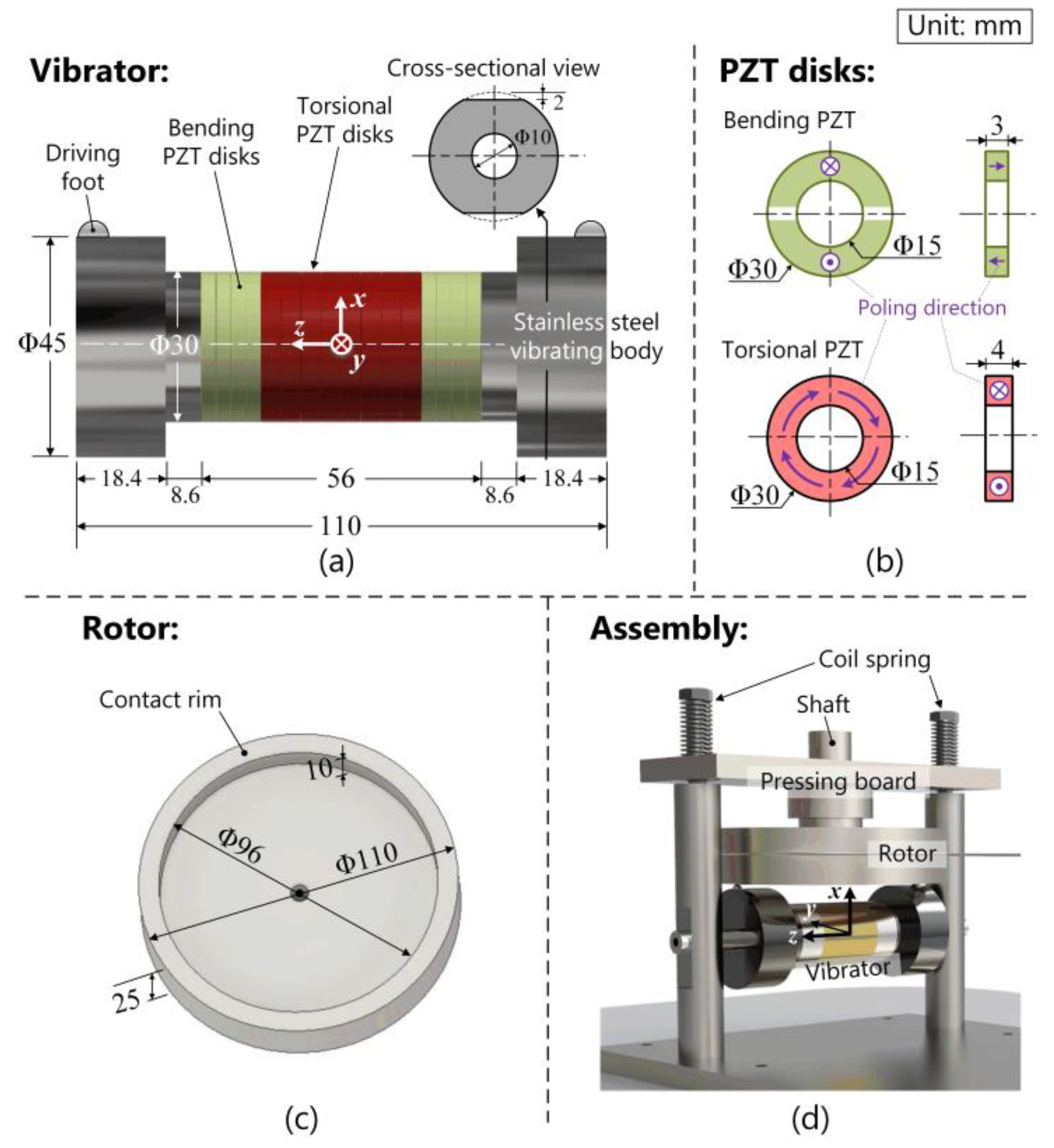
Determine the material of each part. Here, stainless steel (elastic modulus: 197 GPa, density: 7800 kg/m3, and Poisson’s ratio: 0.29) was chosen for the vibrating bodies. The density of the PZT ceramics, provided with our agent, is 7700 kg/m3 and the elastic, piezoelectric, and dielectric matric are as follows:
[ c E ] = [ 78 42 20 42 78 20 20 20 72 26 23 23 ] ( GPa ) [ d ] = [ 0 0 0 0 0.70 0 0 0 0 0.70 0 0 0.19 0.19 0.45 0 0 0 ] × 10 9 ( C / N )
and
[ ε S ] = [ 22.13 0 0 0 22.13 0 0 0 15.93 ] × 10 9 ( F / m )
Figure 1b shows the dimensions and the poling directions of PZT disks. The flexural PZT disks (30 mm in outer diameter, 15 mm in inner diameter, and 3 mm in thickness) were divided into two parts with opposite poling directions, while the torsional ones (30 mm in outer diameter, 15 mm in inner diameter, and 4 mm in thickness) were poled in the circumferential direction. The PZT disks were clamped between the vibrating bodies with a stainless-steel screw.
(2)
Arrange the PZT disks. Since the motor works in the 1st-order torsional and the 1st-order flexural modes, the torsional PZT disks were set in the middle part of the vibrator. Additionally, the central position of the flexural PZT disks located at the node of the flexural mode. By solving the Equation [21]:
cos [ 4.73 l ( Δ l + l 2 ) ] + cosh [ 4.73 l ( Δ l + l 2 ) ] 1.02 { sin [ 4.73 l ( Δ l + l 2 ) ] + sinh [ 4.73 l ( Δ l + l 2 ) ] } = 0 ,
it can be found that the distance between the flexural mode’s node and the vibrator’s middle surface (Δl) should be equal to 0.275 times of the vibrator’s entire length (l). Then, the number of PZT disks were determined according to the distance between each node and the PZT disks’ thicknesses.
(3)
Decide the dominant diameters. Here, the diameters of the vibrating bodies adjacent to the PZT disks were set to 30 mm, as torsional PZT in this diameter is easy to produce.
(4)
Conduct modal degeneration. Through the finite element method (FEM; software ANSYS 14.0, ANSYS Incorporated, Canonsburg, PA, USA.), the lengths of the vibrating bodies’ bilateral outer parts were adjusted to gather the resonance frequencies of the flexural and torsional vibrations. Here, the FEM model of the vibrator was meshed with hexahedron elements, whose types were SOLID227 and SOLID5 for, respectively, the vibrating bodies and the PZT disks. The electrodes were neglected as they are too thin for meshing. Figure 1a also gives the final values of each dimension. The vibrating bodies include two steps: the outer step with a circumferential surface are 45 mm in diameter and 18.4 mm in length, while the inner step 30 mm in diameter and 8.6 mm in length contacts the PZT disks.
(5)
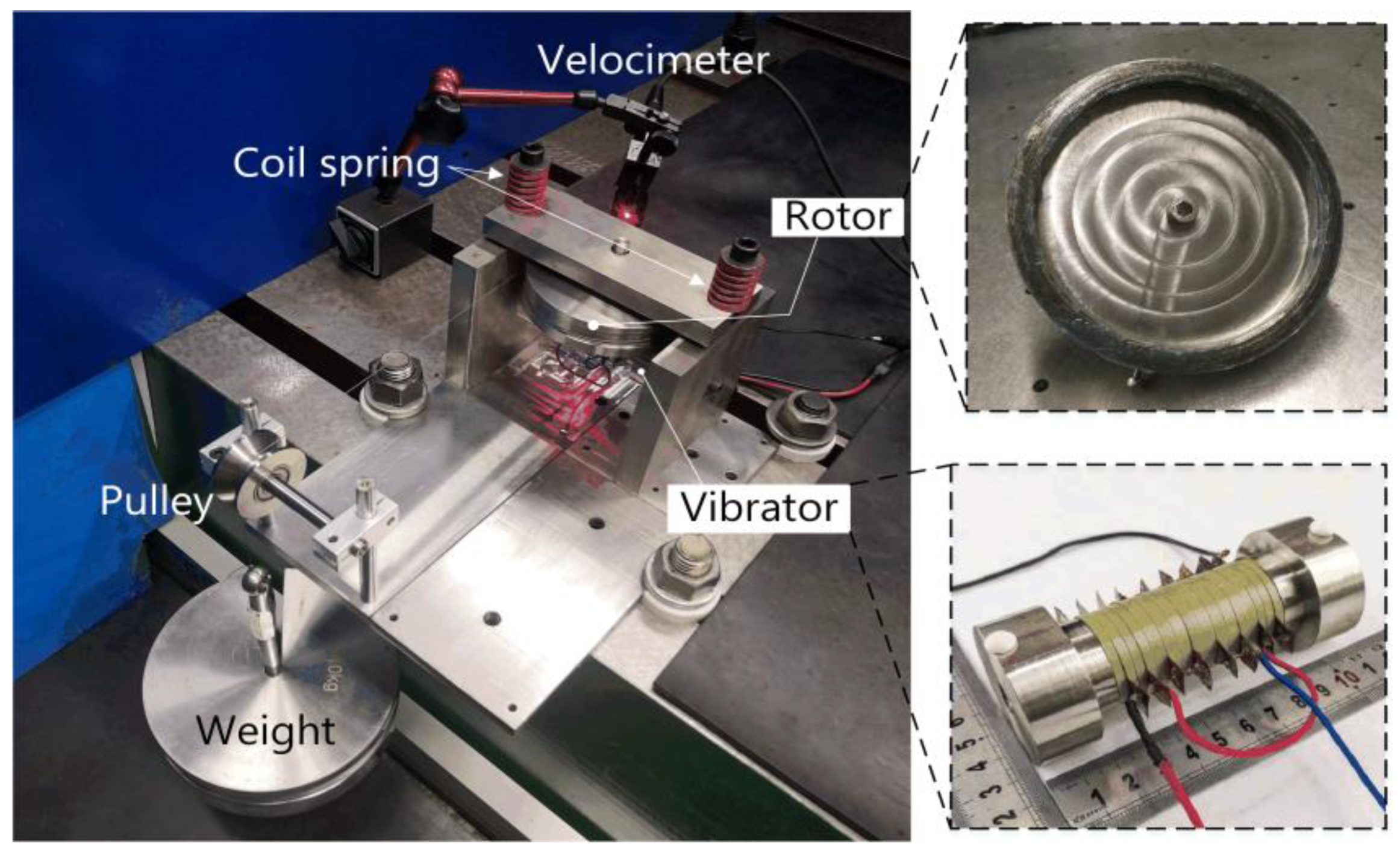
Design the accessory components. First, two polymetric hemispheres were fixed near the vibrator’s edges as the driving feet. Second, Figure 1c illustrates the configuration of the rotor, whose contact rim had the width and height of, respectively, 12 and 10 mm. Third, Figure 1d shows the assembly of the T/F motor. Observably, the rotor was pressed orthogonally to the vibrator by tightening two coil springs. Since the driving-feet distance was approximately equal to the rotor’s diameter, the elliptical motions existing on two driving feet frictionally drove the rotor.
Figure 2 shows the photo of the vibrator prototype, which weights 0.89 kg.

2.2. Working Principle

Figure 3 illustrates the working principle of the T/F motor. The voltages applied to the flexural and torsional PZT disks were, respectively, U0 sin (ωt) and U0 cos (ωt), where U0, ω, and t represent the voltage amplitude, angular frequency, and time, respectively. The vibration velocities and vibration displacements are shown in Table 1, where Af and At denote the flexural and torsional vibration amplitudes, respectively, and n represents an integer.
Accordingly, the sequence of the motion is given as:
(1)
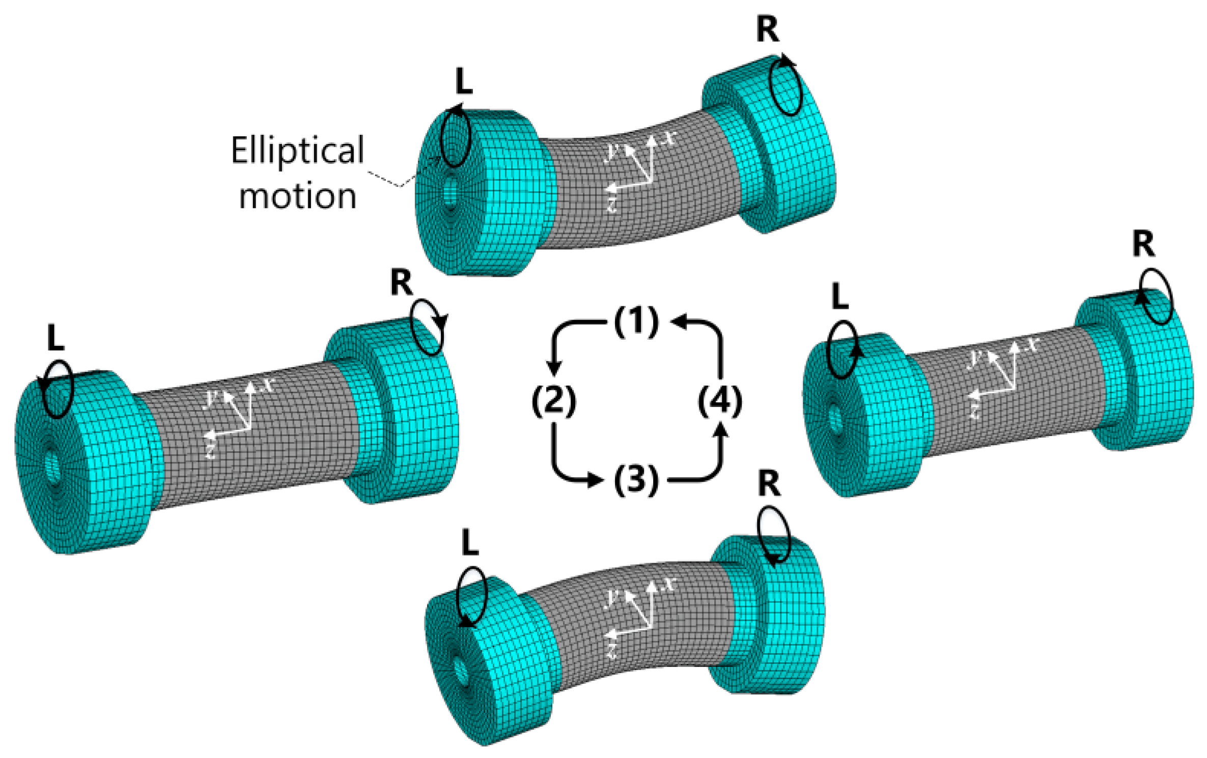
At ωt = 0, the torsional vibration velocity reaches the peak value. Meanwhile, the flexural vibration displacement is maximal in the +x axis. Since the vibrator operates in the 1st torsional mode, the torsional vibration velocities at left (L) and right (R) points are in inverse directions.
(2)
At ωt = 90°, the torsional vibration velocity and the flexural vibration displacement are zero.
(3)
At ωt = 180°, the torsional vibration velocity is maximal but the direction is inverse to those in step (1). On the other hand, the flexural vibration displacement is maximal in the-x axis.
(4)
At ωt = 270°, the torsional vibration velocity and the flexural vibration displacement are zero.
When the voltages applied to the flexural and torsional PZT disks are −U0 sin (ωt) and U0 cos (ωt), the sequence becomes (1)–(4)–(3)–(2); in this case, the rotation direction was inverse to that corresponding to the voltages of U0 sin (ωt) and U0 cos (ωt).

3. Vibration Properties

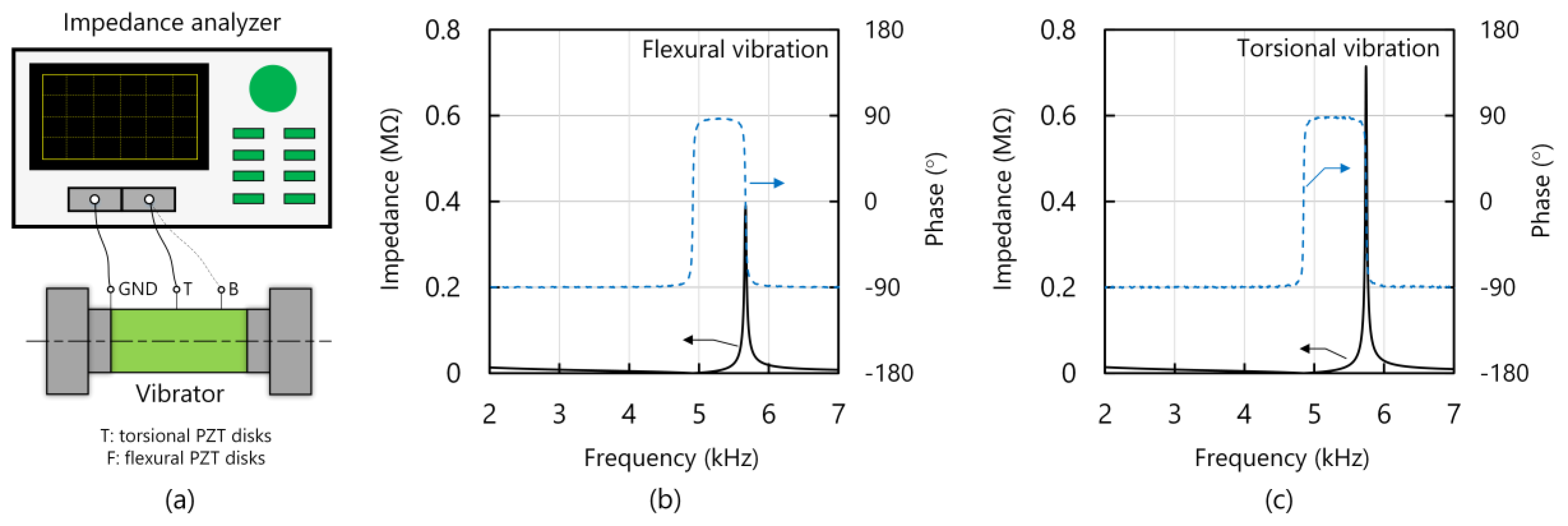
3.1. Impedance Characteristics

First, the impedance characteristics of the vibrator were explored with the testbed shown in Figure 4a. The electrical ports corresponding to the flexural (or torsional) PZT disks and the ground were connected to the impedance analyzer (4294 A, Agilent, Santa Clara, CA, USA.). Figure 4b,c illustrate the impedance curves of the flexural and torsional vibrations, respectively. To further evaluate the impedance characteristics, some equivalent circuit parameters were estimated as follows [1,2,14]: initially, the resonance frequency (fr), the anti-resonance frequency (fa), mechanical quality factor (Qm), and the motional resistance (Rm) could be directly obtained from the impedance curve. Subsequently, the electromechanical coupling factor (k), motional inductance (Lm), and motional capacitance (Cm) were calculated with the following equations [22,23,24,25]:
k = 1 ( f r f a ) 2 ,
L m = Q m R m 2 π f r ,
and
C m = 1 2 π f r Q m R m .
Table 2 lists the results. The fr discrepancy was <0.1 kHz between the torsional and flexural vibrations, satisfactorily small for driving the piezoelectric motor. The k was 1.2 times higher for the torsional than for the flexural vibration. Because of the high Q factor, Rm corresponding to the torsional vibration was relatively high compared to that of the flexural vibration; this feature implies that the mechanical loss induced by torsional vibration was relatively low [1,18]. Here, since we aimed to prove the potential of using torsional and flexural vibrations to achieve high performance, we adopted a simple structure to achieve modal degeneration; this caused fr to be in the audible range. In the future, we will shorten the vibrator to change fr into the inaudible range [18,26,27,28,29,30].

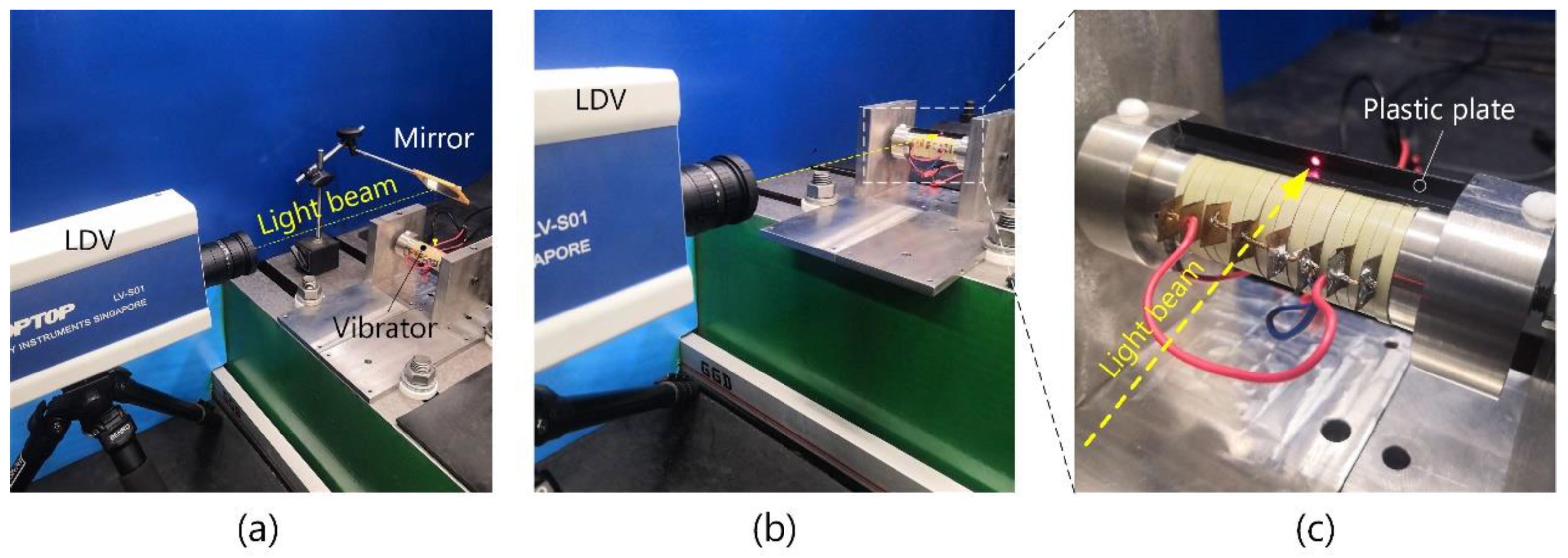
3.2. Vibration Velocity Distribution

Then, the vibration velocity distributions were measured to confirm whether the designed vibrations were excited. The vibrator was fixed to a frame with a screw. As shown in Figure 5a, the torsional and flexural vibration velocities were measured with an out-of-plane laser Doppler vibrometer (LDV; type LV-S01, Sunny Optical Corporation, Yuyao, China) [31]. In the measurements, the LDV was arranged horizontally and the light beam’s direction was changed with a mirror. Different from the flexural vibration velocity, the torsional vibration velocity was in plane, which is theoretically difficult to directly measure with an out-of-plane LDV. As shown in Figure 5b,c, we set the illumination point on a plastic plate bonded to the vibrator. Since the plastic material has far lower density than the stainless-steel vibrating body, the plate should show negligibly small effect on the vibration properties. It is also worth mentioning that, as shown in Figure 6, the in-plane vibration velocity measured by the aforementioned method showed a linear velocity (in the y axis), equal to the product of the angular torsional vibration velocity (in the z axis) and the radii. Here, the torsional vibration velocities shown in Figure 6b were in the angular form.
Figure 6a,b illustrate torsional and flexural vibration velocity distributions, respectively. The voltage amplitude and the working frequency was, respectively, 50 V and 4.837 kHz. Here, the driving frequency did not markedly deviate from the resonance frequency measured with the impedance analyzer; this indicates little effect of the fixing mechanism on the vibration properties [29,30,31]. Additionally, the experimental results well agree with the simulated ones; this implies the successful excitation of the first-order torsional and first-order flexural vibrations.

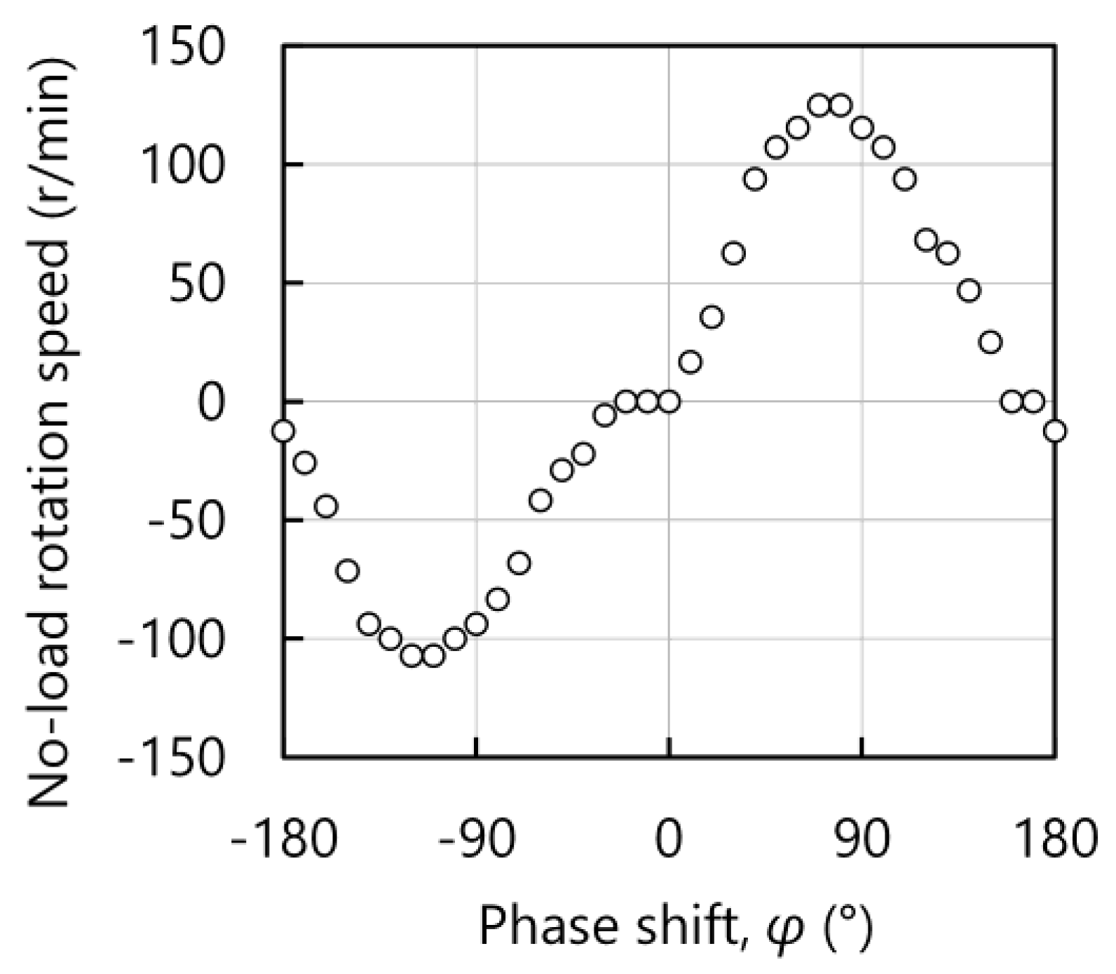
4. Load Characteristics

Figure 7 illustrates the testbed for measuring the T/F motor’s load characteristics. The preload was orthogonally applied to the vibrator by tightening the coil springs. The torque τ was measured by pulling up the weight and the rotation speed θ was estimated with a rotation meter (HG200, Aero-top Hitech Corporation, Beijing, China). The input power Pin was measured with power meters (3332, Hioki Corporation, Nagano, Japan). The efficiency is that
η = τ θ P i n × 100 % .
Figure 8 shows the variation in no-load rotation speed versus the phase shift between the voltages applied to the torsional and flexural vibration. The no-load rotation speed reached the peak values along the counter-clockwise and clockwise directions when the phases were −110° and 70°, respectively.
Figure 9a–c plot the variations in rotation speed, output power, and efficiency versus torque, respectively. The working frequency and the preload were set to 4.678 kHz and 600 N, respectively. The working frequency was slightly smaller than the resonance frequency dominantly because the vibration loss and the PZT’s elastic compliance become larger with increasing voltage [32,33]. When the voltage had the zero-to-peak amplitude of 250 V, the motor yielded the maximal rotation speed of 125 r/min and the torque of 4.3 Nm. Meanwhile, the maximal output power and the maximal efficiency were, respectively, 16.9 W and 10.5%. At 200 V, the no-load rotation speed decreased to 97 r/min. The efficiency was <5% probably because the frictional loss became larger.
Table 3 compares the T/F motor’s performance with several other motors based on d15 modes. Compared to Yan’s micro motor working in the T/T modes [2], the T/F motor exhibited high torque density and high power density despite its large profile. In addition, Satonobu’s T/L motor provided larger torque because the longitudinal vibration produces large normal force, which may enhance the frictional force to drive the rotor [5]. However, the T/L motor provided lower output power than the T/F one because undesirable vibrations exist on the vibrator especially when the diameter-to-length ratio approaches one. Additionally, in the fabrication of torsional PZT, several wedge-shaped PZT pieces should be independently prepared and bonded with each other; this procedure causes higher expense of making torsional PZT than other types particularly in the small batch of producing torsional PZT. However, the production expenses of a large amount of the T/F motors was assumed to have a small difference compared to other types of piezoelectric motors as the workloads for making a large batch of PZT disks in d33, d31, and d15 modes did not have significant difference. Thus, these comparisons allow us to infer that superposition of torsional and flexural vibrations is suitable for piezoelectric motors.

5. Conclusions

In this study, we produced a dumbbell-shaped vibrator with the first-order torsional and first-order flexural modes, and used it to form a piezoelectric motor, where the maximal torque, the maximal rotation speed, and maximal output power reached 4.3 Nm, 125 r/min, and 16.9 W, respectively. These results imply the suitability of torsional/flexural vibrations for piezoelectric motors. In further studies, we would like to, as mentioned above, increase the working frequency into the inaudible range by shortening the vibrator’s length [34,35]. Additionally, we will model the T/F motor and conduct structural optimization in the future [34,36].

Author Contributions

Conceptualization, J.W. and S.G.; methodology, J.N.; software, Q.L.; validation, J.N. and L.C.; formal analysis, J.N.; investigation, J.W.; data curation, L.C. and J.N.; writing—original draft preparation, J.W.; writing—review and editing, J.N., J.W and Q.L.; supervision, S.G.; project administration, S.G.; funding acquisition, J.N., J.W., Q.L. and S.G. All authors have read and agreed to the published version of the manuscript.

Funding

This work was supported partly by the China Postdoctoral Science Foundation (Grant No. 2019M660964, 2019M660963 and 2020T130167), partly by the Science and Technology (S&T) Program of Hebei (Grant No. E2020103001), partly by the Funding of Hebei Provincial Department of Human Resource and Social Security of China (Grant No. 202003019), and partly by the Open Fund of State Key Laboratory of Advanced Design and Manufacturing for Vehicle Body (Grant No. 31915004).

Conflicts of Interest

The authors declare no conflict of interest.

References

  1. Ueha, S.; Tomikawa, Y.; Kurosawa, M.; Nakamura, K. Ultrasonic Motors—Theory and Applications; Oxford University Press: New York, NY, USA, 1993; pp. 4–13. [Google Scholar]
  2. Yan, L.; Liu, D.; Lan, H.; Jiao, Z. Compact traveling wave micromotor based on shear electromechanical coupling. IEEE/ASME Trans. Mechatron. 2016, 21, 1572–1580. [Google Scholar] [CrossRef]
  3. Dong, S.; Zhang, J.; Kim, H.W.; Strauss, M.T.; Uchino, K.; Viehland, D. Flexural traveling wave excitation based on shear-shear mode. IEEE Trans. Ultrason. Ferroelectr. Freq. Control 2004, 51, 1240–1246. [Google Scholar] [CrossRef]
  4. Gao, X.; Xin, X.; Wu, J.; Chu, Z.; Dong, S. A multilayered-cylindrical piezoelectric shear actuator operating in shear (d15) mode. Appl. Phys. Lett. 2018, 112, 152902. [Google Scholar] [CrossRef] [Green Version]
  5. Satonobu, J.; Torii, N.; Nakamura, K.; Ueha, S. Construction of mega-torque hybrid transducer type ultrasonic motor. Jpn. J. Appl. Phys. 1997, 35, 5038–5042. [Google Scholar] [CrossRef]
  6. Liu, Y.; Chen, W.; Liu, J.; Yang, X. A high-power linear ultrasonic motor using bending vibration transducer. IEEE Trans. Ind. Electron. 2012, 60, 5160–5166. [Google Scholar] [CrossRef]
  7. Wang, L.; Hofmann, V.; Bai, F.; Jin, J.; Twiefel, J. Modeling of coupled longitudinal and bending vibrations in a sandwich type piezoelectric transducer utilizing the transfer matrix method. Mech. Syst. Signal Process. 2018, 108, 216–237. [Google Scholar] [CrossRef]
  8. Nakamura, K.; Kurosawa, M.; Ueha, S. Design of a hybrid transducer type ultrasonic motor. IEEE Trans. Ultrason. Ferroelectr. Freq. Control 1993, 40, 395–3401. [Google Scholar] [CrossRef]
  9. Nakamura, K.; Ueha, S. Potential ability of ultrasonic motors: A discussion focused on the friction control mechanism. Electron. Commun. Jpn. Part II Electron. 1998, 81, 57–68. [Google Scholar] [CrossRef]
  10. Cao, T.; Li, X.; Wang, B.; Mi, Y.; Zhao, G.; Twiefel, J.; Wu, D. Viscoelastic analytical model and design of polymer-based bimodal piezoelectric motor. Mech. Syst. Signal Process. 2020, 145, 106960. [Google Scholar] [CrossRef]
  11. Zhang, Q.; Chen, W.; Liu, Y.; Liu, J.; Jiang, Q. A frog-shaped linear piezoelectric actuator using first-order longitudinal vibration mode. IEEE Trans. Ind. Electron. 2016, 64, 2188–2195. [Google Scholar] [CrossRef]
  12. Xu, D.; Liu, Y.; Shi, S.; Chen, W.; Wang, L. Development of a non-resonant piezoelectric motor with nanometer resolution driving ability. IEEE/ASME Trans. Mechatron. 2018, 23, 444–451. [Google Scholar] [CrossRef]
  13. Deng, J.; Liu, Y.; Chen, W.; Yu, H. A XY transporting and nano-positioning piezoelectric robot operated by leg rowing mechanism. IEEE/ASME Trans. Mechatron. 2019, 24, 207–217. [Google Scholar] [CrossRef]
  14. Wu, J.; Mizuno, Y.; Nakamura, K. Polymer-based ultrasonic motors utilizing high-order vibration modes. IEEE/ASME Trans. Mechatron. 2018, 23, 788–799. [Google Scholar] [CrossRef]
  15. Nakamura, K.; Isago, R.; Koyama, D. Endoscopic optical coherence elastography using acoustic radiation force and a vibrating fiber. AIP Conf. Proc. 2012, 1474, 247–250. [Google Scholar]
  16. Liu, Y.; Yan, J.; Wang, L.; Chen, W. A Two-dof ultrasonic motor using a longitudinal-bending hybrid sandwich transducer. IEEE Trans. Ind. Electron. 2019, 66, 3041–3050. [Google Scholar] [CrossRef]
  17. Pan, S.; Wang, D.; Huang, W. A novel small motor measurement system based on ultrasonic bearings. Measurement 2021, 168, 108307. [Google Scholar] [CrossRef]
  18. Liu, Y.; Chen, W.; Yang, X.; Liu, J. A rotary piezoelectric actuator using the third and fourth bending vibration modes. IEEE Trans. Ind. Electron. 2014, 61, 4366–4373. [Google Scholar] [CrossRef]
  19. Wu, J.; Mizuno, Y.; Tabaru, M.; Mizuno, Y. Ultrasonic motors with polymer-based vibrators. IEEE Trans. Ultrason. Ferroelectr. Freq. Control 2015, 62, 2169–2178. [Google Scholar] [CrossRef]
  20. Huang, Z.; Shi, S.; Chen, W.; Wang, L.; Wu, L.; Liu, Y. Development of a novel spherical stator multi-DOF ultrasonic motor using in-plane non-axisymmetric mode. Mech. Syst. Signal Process. 2020, 140, 106658. [Google Scholar] [CrossRef]
  21. Graff, K.F. Wave Motions in Elastic Solids; Dover: New York, NY, USA, 1991; pp. 169–180. [Google Scholar]
  22. Wu, J.; Mizuno, Y.; Nakamura, K. Piezoelectric motor utilizing an alumina/PZT transducer. IEEE Trans. Ind. Electron. 2020, 67, 6762–6772. [Google Scholar] [CrossRef]
  23. Nakamura, K. Ultrasonic Transducers: Materials and Design for Sensors, Actuators, and Medical Applications; Woodhead Publishing Limited: Cambridge, UK, 2012; pp. 677–704. [Google Scholar]
  24. Morita, T. Piezoelectric Phenomena; Morikita Publication: Tokyo, Japan, 2017; pp. 86–94. (In Japanese) [Google Scholar]
  25. Deng, J.; Chen, W.; Wang, Y.; Zhang, S.; Liu, Y. Modeling and experimental evaluations of a four-legged stepper rotary precision piezoelectric stage. Mech. Syst. Signal Process. 2019, 132, 153–167. [Google Scholar] [CrossRef]
  26. Wang, L.; Guan, Y.; Liu, Y.; Deng, J.; Liu, J. A compact cantilever-type ultrasonic motor with nanometer resolution: Design and performance evaluation. IEEE Trans. Ind. Electron. 2021, 68, 734–743. [Google Scholar] [CrossRef]
  27. Nakamura, K. Evaluation methods for materials for power ultrasonic applications. Jpn. J. Appl. Phys. 2020, 59, SK0801. [Google Scholar] [CrossRef]
  28. Izuhara, S.; Mashimo, T. Linear piezoelectric motor using a hollow rectangular stator. Sens. Actuators A Phys. 2020, 309, 112002. [Google Scholar] [CrossRef]
  29. Wang, L.; Xue, C.; Hofmann, V.; Bai, F.; Jin, J.; Twiefel, J. Semi-analytical modeling and optimization of a traveling wave sandwich piezoelectric transducer with a beam-ring combined structure. Mech. Syst. Signal Process. 2019, 122, 171–191. [Google Scholar] [CrossRef]
  30. Zhang, S.; Liu, Y.; Deng, J.; Tian, X.; Gao, X. Development of a two-DOF inertial rotary motor using a piezoelectric actuator constructed on four bimorphs. Mech. Syst. Signal Process. 2021, 149, 107213. [Google Scholar] [CrossRef]
  31. Dong, H.; Yu, Z.; Grattan, K.T.V.; Sun, T.; Li, T. Acoustic standing wave field measurement using a laser doppler vibrometer based on the Hankel Fourier algorithm. IEEE Access 2019, 7, 139013–139020. [Google Scholar] [CrossRef]
  32. Slabki, M.; Wu, J.; Weber, M.; Breckner, P.; Isaia, D.; Nakamura, K.; Koruza, J. Anisotropy of the high-power piezoelectric properties of Pb(Zr, Li)O3. J. Am. Ceram. Soc. 2019, 102, 6008–6017. [Google Scholar] [CrossRef]
  33. Wu, J.; Mizuno, Y.; Nakamura, K. Structural parameter study on polymer-based ultrasonic motor. Smart Mater. Struct. 2017, 26, 115022. [Google Scholar] [CrossRef]
  34. Xu, Z.; Pan, S.; Chen, L.; Di, S.; Huang, W. A continuously variable beam expander driven by ultrasonic motors. Rev. Sci. Instrum. 2019, 90, 096107. [Google Scholar] [CrossRef]
  35. Li, X.; Yao, Z.; Li, R.; Wu, D. Dynamics modeling and control of a V-shaped ultrasonic motor with two Langevin-type transducers. Smart Mater. Struct. 2020, 29, 025018. [Google Scholar] [CrossRef]
  36. An, D.; Yang, M.; Zhuang, X.; Yang, T.; Meng, F.; Dong, Z. Dual traveling wave rotary ultrasonic motor with single active vibrator. Appl. Phys. Lett. 2017, 110, 143507. [Google Scholar] [CrossRef]
Figure 1. Schematic of the T/F motor. (a) The transducer’s configuration, (b) poling direction of flexural and torsional PZT disks, (c) the rotor’s structure, and (d) the assembly. A Cartesian coordinate (x, y, and z axes) is built on the middle surface of the transducer.
Actuators 09 00124 g001
Figure 2. Photograph of the transducer prototype.
Actuators 09 00124 g002
Figure 3. Working principle of the T/F motor. Deformations for the vibration modes are given and the arrows in each circle indicates the direction of each elliptical motion.
Actuators 09 00124 g003
Figure 4. (a) Schematic of the testbed for measuring the impedance characteristics. The impedance characteristics corresponding to (b) the flexural vibration and (c) the torsional vibration.
Actuators 09 00124 g004
Figure 5. Experimental setup for measuring (a) flexural and (b) torsional vibration velocity distributions. (c) shows the plastic plate bonded onto the vibrator.
Actuators 09 00124 g005
Figure 6. (a) Flexural and (b) torsional vibration velocity distributions in the z axis. The dots and curves indicate the measured and simulated results, respectively.
Actuators 09 00124 g006
Figure 7. Experimental setup for measuring the load characteristics.
Actuators 09 00124 g007
Figure 8. No-load rotation speed as a function of the phase shift of the voltages applied to torsional and flexural vibrations. The voltages applied to the flexural and torsional PZT disks have the phase shift φ.
Actuators 09 00124 g008
Figure 9. Load characteristics: (a) rotation speed, (b) output power, and (c) efficiency vs. torque.
Actuators 09 00124 g009
Table 1. Vibration velocities and vibration displacements at different time.
TimePointVibration VelocityVibration Displacement
FlexuralTorsionalFlexuralTorsional
ωt = 0 + 360° nL0ωAtAf0
R0ωAtAf0
ωt = 90° + 360° nLωAf00At
RωAf00At
ωt = 180° + 360° nL0ωAtAf0
R0ωAtAf0
ωt = 270° + 360° nL−ωAf00At
R−ωAf00At
Table 2. Equivalent circuit parameters of the T/F vibrator.
Flexural VibrationTorsional Vibration
Resonance frequency, fr (kHz)4.9114.838
Anti-resonance frequency, fa (kHz)5.0705.058
Electromechanical coupling factor, k24.8%29.2%
Mechanical quality factor, Qm215302
Motional admittance, Ym0 (mS)9.314.1
Motional resistance, Rm (Ω)107.770.9
Motional inductance, Lm (H)0.7500.705
Motional capacitance, Cm (nF)1.401.53
Table 3. Performance comparison between our motor and those driven with torsional modes.
This Motor[2][5]
Vibration modesT/FT/TT/L
StructureCylindricalSquare barCylindrical
Dimension (mm)Φ45 × 1101.55 × 0.75 × 0.75Φ60 × 72
Weight (kg)0.891.9 × 10−51.1
Maximal torque (Nm)4.32.5 × 10−68
No-load rotation speed (r/min)125700
Maximal output power (W)16.98.3 × 10−53
Maximal efficiency10.5%<15%
Torque density (Nm/kg)4.80.17.3
Power density (W/kg)19.04.32.7
Publisher’s Note: MDPI stays neutral with regard to jurisdictional claims in published maps and institutional affiliations.

