Article

A Miniaturized Dual-Slider Linear Actuator Using Electrostatic Adhesion and Inertia Drive

1
Department of Sports Science, Zhejiang University, Hangzhou 310028, China
2
Department of Mechanical and Energy Engineering, Southern University of Science and Technology, Shenzhen 518055, China
3
Harbin Institute of Technology Shenzhen Graduate School, Shenzhen 518000, China
4
School of Big Data & Software Engineering, Chongqing University, Chongqing 400044, China
*
Authors to whom correspondence should be addressed.
Actuators 2020, 9(4), 114; https://doi.org/10.3390/act9040114
Submission received: 3 October 2020 / Revised: 7 November 2020 / Accepted: 10 November 2020 / Published: 12 November 2020
(This article belongs to the Section Precision Actuators)

Abstract

:
Dual-slider positioning in a miniaturized system is crucial in many industrial applications. This paper presents a miniaturized dual-slider linear actuator by employing one piezoelectric element (PZT) and integrating the methods of electrostatic adhesion and inertia drive. Two inertia drive methods can be converted by clamping and releasing one of the sliders on a base. Two thin-film electrodes are mounted on the base for clamping and releasing the slider by electrostatic adhesion. The actuator can thus drive dual sliders independently by converting the two inertia drive methods. A prototype is developed with a compact size of 30 mm (L) × 11 mm (W) × 11 mm (H) to evaluate the basic performance of the actuator. The maximum driving speeds of the two sliders are 31.7 mm/s and 16 mm/s, respectively, while the resolution of them is 60 nm and 13 nm, respectively. Additionally, the actuator can drive both the two sliders for long motion ranges of 14 mm. With a compact size and excellent physical performance, the proposed device has the potential for multi-slider positioning in miniaturized equipment.

1. Introduction

High precision linear actuators are required in a wide range of industrial applications for positioning sliders. For example, they can be employed in positioning optical elements, manufacturing collaborative machines, and manipulating biological samples. In many applications, two or more sliders are required to be positioned independently with long motion ranges as well as high positioning resolution [1,2,3,4,5,6]. One typical example can be found in the zoom lens system. It should have the functions of zooming and auto-focusing, which requires a zooming lens and an auto-focusing lens, respectively. The two lenses should be positioned independently with long motion ranges as well as high resolution. Moreover, with the increasing miniaturization of microelectronic instruments, the small size of the linear actuator is also required.
Piezoelectric elements (PZTs) have many excellent characteristics, such as compact size, high precision, and fast response, which are widely and well applied in the miniaturization of precision positioning linear actuators [7,8,9,10,11,12,13,14]. However, long motion range positioning is unable to be achieved by the limited stroke of a PZT. Thus, many methods have been designed to enlarge the extremely small stroke of the PZT. The most effective approach is to accumulate step motions of the PZT, which can not only generate long range movement through repetition and accumulation of the micro stroke of the PZT, but also can position high resolution during one step motion. Two typical types of this method are the clamping drive method and the inertia drive method [13,14,15,16,17,18]. In the clamping drive method, the actuator is driven by clamping and feeding the PZT step by step, such as inchworm mechanisms, seal mechanisms, and walking drive mechanisms [13,14]. A clamping drive mechanism can generate a large driving force, but it needs at least one clamping mechanism and one feeding mechanism, leading to large volume, complicated structure, sophisticated control, limited driving frequency, and mechanical vibration. In comparison with the clamping drive method, the inertia drive method represented by the impact drive mechanism (IDM) and the smooth impact drive mechanism (SIDM) [8,9,10,11,12,13,14,15,16,17,18,19,20,21,22,23], which utilizes inertia and friction force to generate a long motion range, has simpler construction, wider bandwidth, and less vibration. Traditionally, one IDM or SIDM-based linear actuator can position only one slider, and most studies always used two or more actuators for dual-slider positioning [5,6]. However, space-consuming setup and sophisticated control will be caused by the two-actuator structure, which limits its application in miniaturized instruments.
To overcome this dilemma, this paper proposes a miniaturized dual-slider linear actuator by using only one PZT to combine the IDM and SIDM operation modes. The IDM and SIDM modes could be converted by electrostatic adhesion. Two thin-film surface-insulated copper electrodes, which are mounted on two sides of the V-shaped groove of the linear actuator, are employed for clamping and releasing one of the sliders by electrostatic adhesion. Therefore, two sliders can be positioned independently with long motion ranges as well as high positioning resolution in the IDM and SIDM modes, respectively. Compared to electromagnetic clamping mechanisms with large volumes of components, the thin-film copper electrodes can generate electrostatic adhesion with an extremely small size, which can miniaturize the dual-slider linear actuator with a simple structure [3,24,25]. The principle and design of the dual-slider linear actuator integrating electrostatic adhesion and inertia drive methods, together with experimental results, are presented.

2. Principle and Design of the Linear Actuator

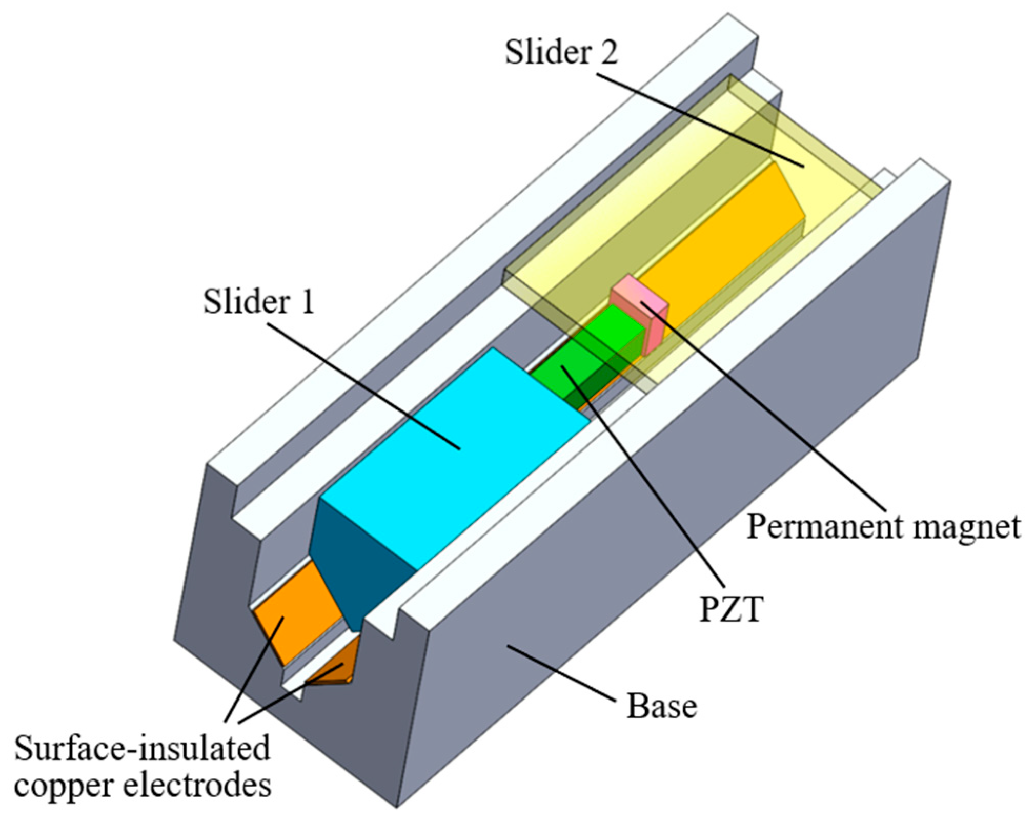
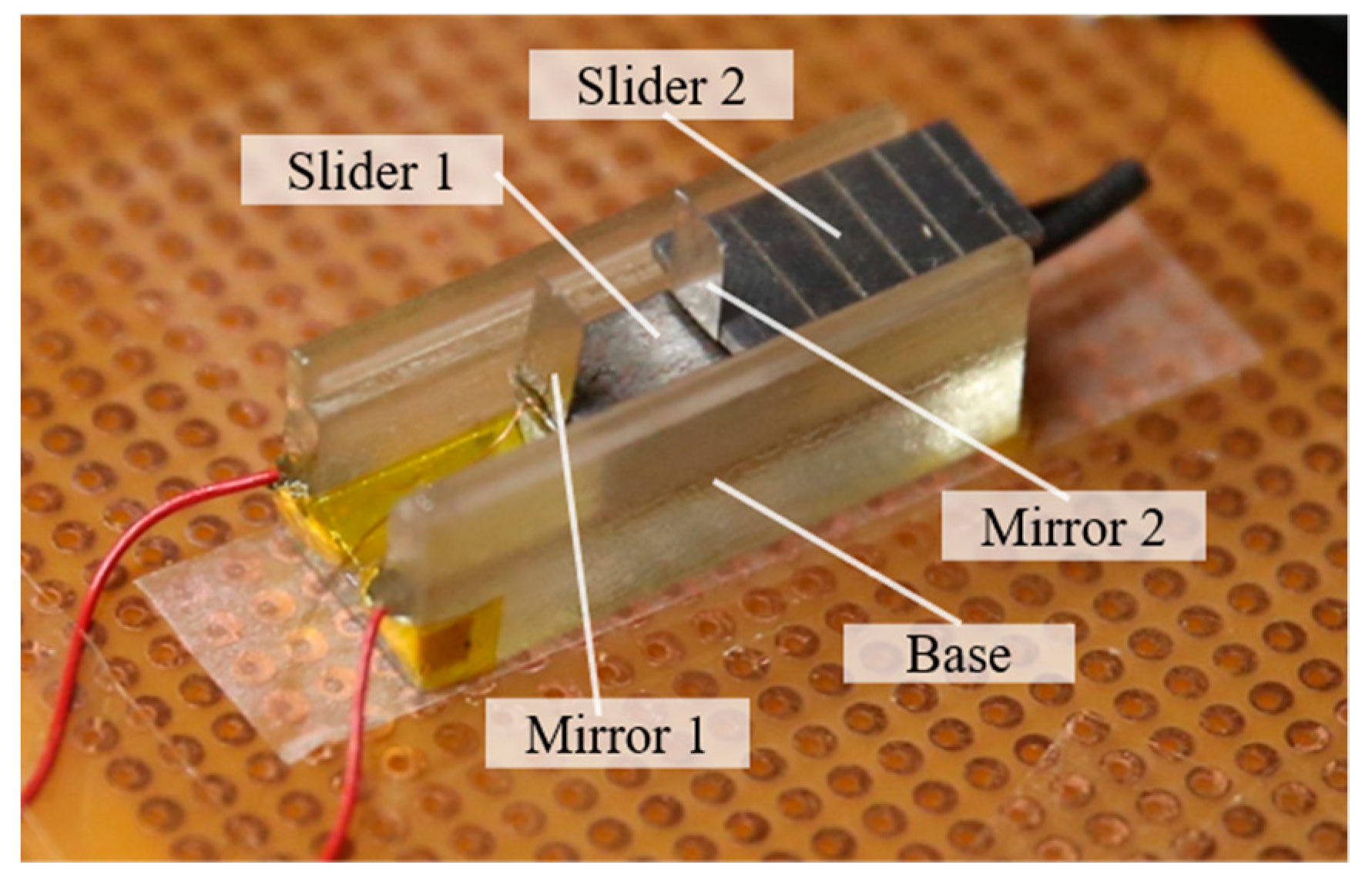
2.1. Design of the Dual-Slider Linear Actuator

The configuration of the dual-slider linear actuator is shown in Figure 1. The proposed actuator consists of a slider 1, a slider 2, a PZT, a permanent magnet, two surface-insulated copper electrode films, and a base. The base is designed with an upper groove and a lower V-shaped groove. Both the sliders 1 and 2 are made of stainless steel. The slider 1 is a pentagonal prism with 10 mm height and 1.65 g weight, which is suited to the lower V-shaped groove of the base. The slider 2, which is a steel plate with a size of 15 mm (L) × 8 mm (W) × 1 mm (H) and weight of 0.85 g, is suited to the upper groove of the base. The two copper electrode films, which are insulated by polyimide (PI) film on the surfaces, are mounted on the two sides of the V-shaped groove, respectively. To separate the two surface-insulated copper electrode films, a small, elongated groove is designed at the bottom of the V-shaped groove. By turning on and off an applied voltage, electrostatic force can be generated between the copper electrode films and the slider 1 for clamping and releasing the slider 1, respectively. The base, with a length of 30 mm, is made of insulated plastic to eliminate its influence on electrostatic effects. Two terminals of the PZT are glued to the slider 1 and the permanent magnet, respectively. The permanent magnet is attached on the slider 2 by the magnetic force. Note that there is a certain gap between the sliders 1 and 2 so that the slider 2 can move freely along the upper groove. The permanent magnet for holding the slider 2 is as small as 1 mm (L) × 2 mm (W) × 2 mm (H), and its weight is 0.03 g. Considering the small size of the slider 1 and the permanent magnet, the size of the PZT connecting them is selected as 1.65 mm (L) × 1.65 mm (W) × 5 mm (H), with a weight of 0.11 g. The stroke of the PZT is approximately 7.3 μm at 90 V.
Consequently, the motion range of the slider 1 is 14 mm, which is determined by the lengths of the slider 1, the PZT, the permanent magnet, and the base. The motion range of the slider 2, which is not only determined by the lengths of the slider 2 and the base, but also determined by the sliding position of the permanent magnet, is also calculated to be 14 mm.

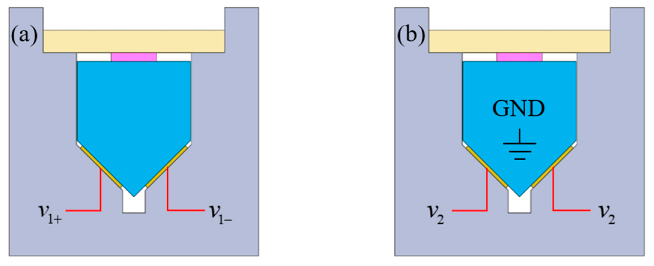
2.2. Electrostatic Adhesion for IDM-SIDM Conversion

For conversion between the IDM and SIDM modes, the slider 1 should release and clamp the base, respectively. Many traditional adhesion devices are large and heavy, so they waste a large amount of the size and weight of the whole system. For example, in the magnetic adhesion, the materials are heavy, including copper wires and iron magnetic cores. However, the electrostatic adhesion usually uses thin electrode films, and its material is extremely light.
In the dual-slider linear actuator, the electrostatic adhesion is implemented by the two electrode films. To stick the slider 1 to the electrode films, two schemes can be employed to generate electrostatic adhesion. In the first scheme (scheme A), inverse voltages are applied to the two copper electrode films. In the other scheme (scheme B), the same voltage is applied to the two copper electrode films, while the slider 1 is grounded. Illustrations for the two schemes are shown in Figure 2.
The model of the whole electrostatic adherence system can be treated as a large capacitor. Considering the air gaps between the isolation layer and the copper electrode film due to the non-absolute flat interfaces, the affection of air gaps is introduced to calibrate the electrostatic adhesive force model. In this model, although air gaps are randomly distributed on the film surfaces, they can be summarized as an empirical constant for compensation. Since the slider 1 is not grounded in the scheme A, it becomes a part of dielectric layer. Thus, the estimated adhesion force in the scheme A is calculated as:
F a d e ( scheme   A ) = 1 2 ε 0 S V 2 ( d 0 + d r ε r + d c ε c ) 2 ,
where ε0, εr, and εc are the permittivities of the vacuum, isolation layer, and slider 1 (mostly iron), respectively; d0, dr, and dc indicate the compensated air gap, the thickness of the isolation layer, and the width of the slider 1, respectively; V and S represent the applied voltage and total area of both electrodes, respectively.
For the scheme B, two electric poles for generating electrostatic force alter from two copper electrodes to the slider 1 and each of the copper electrodes. Thus, the slider 1 no longer acts as a dielectric layer, and the estimated adhesion force in the scheme B can be calculated as:
F a d e ( scheme   B ) = 1 2 ε 0 S V 2 ( d 0 + d r ε r ) 2 .
Although the permittivity of the iron is very high, the denominator in Equation (1) is still larger than the denominator in Equation (2). Thus, the adhesive force generated by the scheme B will be higher than the adhesive force in the scheme A.

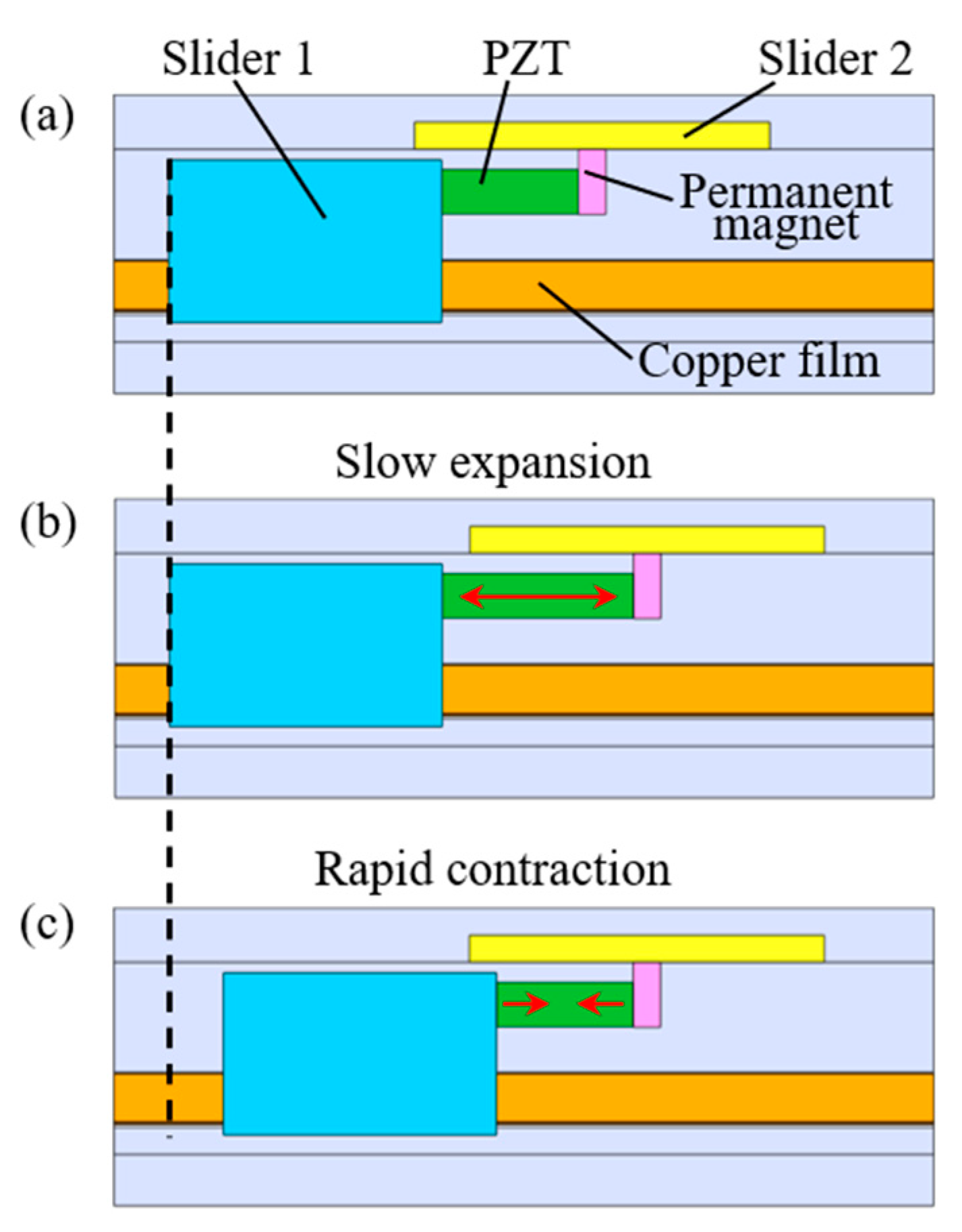
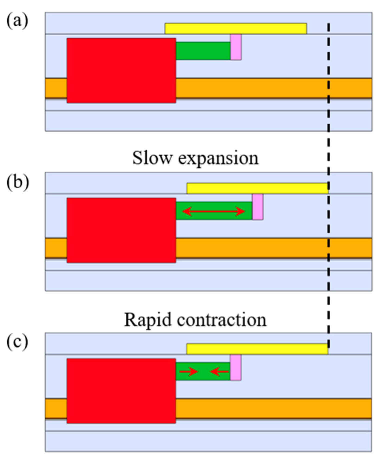
2.3. Inertia Drive for Dual-Slider Positioning

With the help of the electrostatic adhesion for releasing and clamping the slider 1, the actuator can be converted between the IDM and SIDM modes for positioning the sliders 1 and 2, respectively. Both the IDM and SIDM modes can be driven by applying a saw-tooth voltage to the PZT, as shown in Figure 3. In one driving cycle of the IDM or SIDM mode, the PZT is driven by the saw-tooth voltage with a slow increase and rapid decrease to move forward the sliders 1 or 2. The slowly increasing voltages correspond to the slow expansion of the PZT while the rapidly decreasing voltages lead the PZT to rapid contraction. Conversely, the reverse moving direction can be achieved by modifying the voltage to have rapid increase and slow decrease. The driving characteristics of the dual sliders mainly depend on the waveform of the applied voltage to the PZT, including the amplitude, frequency, and duty ratio. In this work, the duty ratio D can be represented as:
D = t 1 t 1 + t 2 × 100 % ,
where t1 and t2 represent the increasing time and decreasing time of a whole cycle, respectively.
The IDM mode for positioning the slider 1 is illustrated in Figure 4. There is no electrostatic adhesion between the copper electrode films and the slider 1 in Figure 4a, and the slider 1 is released from the electrode films and can be driven in the IDM mode. The slider 1 can be positioned by: (b) slowly expanding the PZT to move the permanent magnet while the slider 1 remains stationary due to the static frictional force between the slider 1 and the electrode films; (c) rapidly reducing the PZT voltage to pull the slider 1 towards the permanent magnet due to the conservation of momentum. By repeating the steps from (b) to (c), the slider 1 can be moved in a theoretically infinite range continuously. Since the slider 1 can be moved only when the impact force on the slider 1 exceeds the static frictional force, the positioning resolution depends on the displacement of the step motion in one driving cycle [14].
In the IDM mode, assume that the masses of the slider 1, the slider 2 and the permanent magnet are m1, m2, and mp, respectively. fmax1, fmax2, and fmax3 are the maximum static frictional forces between the slider 1 and the copper electrode films, the slider 2 and the permanent magnet, the slider 2 and the base, respectively. An impact force Fe is generated by slow expansion of the PZT, and an impact force Fc is generated when the PZT rapidly contracts. When the PZT expands slowly, the condition of the forces in the actuator meets
{ f max 3 f max 1 f max 3 f max 2 f max 3 < F e f max 1 .
Unlike traditional IDMs [21,22,23], in the IDM mode of the proposed actuator, the slider 2 moves together with the permanent magnet when the PZT expands slowly. Therefore, the slider 2 and the permanent magnet can be seen as a whole, and their motion can be expressed as
{ ( m 2 + m p ) x ¨ 2 = F e f 3 f max 2 x ˙ 2 = x ¨ 2 t 1 ,
where x2, 2, and 2 denote the displacement, velocity, and acceleration, respectively. f3 is the dynamic frictional force between the slider 2 and the base.
When the PZT contracts rapidly, the linear actuator should meet:
{ F c > f max 1 F c > f max 2 m 2 x ¨ 2 > f max 2 .
The motion of the slider 1 is represented by
{ m 1 x ¨ 1 = F c f 1 x ˙ 1 = x ¨ 1 t 2 ,
where x1, 1, and 1 are the displacement, velocity, and acceleration of the slider 1 in the rapid phase of the applied voltage, respectively. f1 is the dynamic frictional force between the slider 1 and the copper electrode films.
The motion of the slider 2 is represented by
{ m 2 x ¨ 2 = f 2 + f 3 x ˙ 2 = x ˙ 2 x ¨ 2 t 2 ,
where 2 and 2 are the velocity and acceleration of the slider 2, respectively. f2 is the dynamic frictional force between the slider 2 and the permanent magnet.
Like many SIDMs [8,9,10,11,12], the SIDM mode for positioning the slider 2 is illustrated in Figure 5. In Figure 5a, an appropriate voltage is applied to the copper electrode films to switch the actuation mode from the IDM to SIDM. The slider 2 can be positioned by: (b) slowly expanding the PZT to move the slider 2 by the static frictional force between slider 2 and the permanent magnet; (c) rapidly reducing the PZT voltage to pull the permanent magnet back while the slider 2 maintains its position due to its inertia. By repeating the steps from (b) to (c), the slider 2 can be driven continuously with a long motion range. In the SIDM mode, the slider 2 moves together with the PZT due to the static frictional force when the voltage is slowly applied to the PZT. Therefore, the positioning resolution of slider 2 can achieve as high as nanometer level, which is the same as the PZT itself.
Therefore, based on the electrostatic adhesion and inertia drive methods, both the sliders 1 and 2 can be positioned independently with long motion ranges and high resolution.

3. Experiments

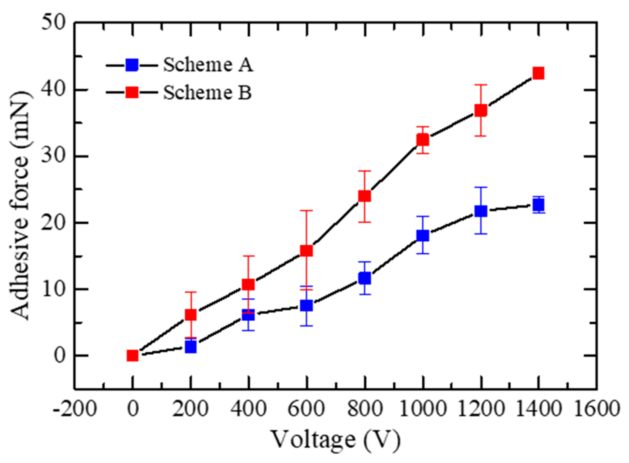
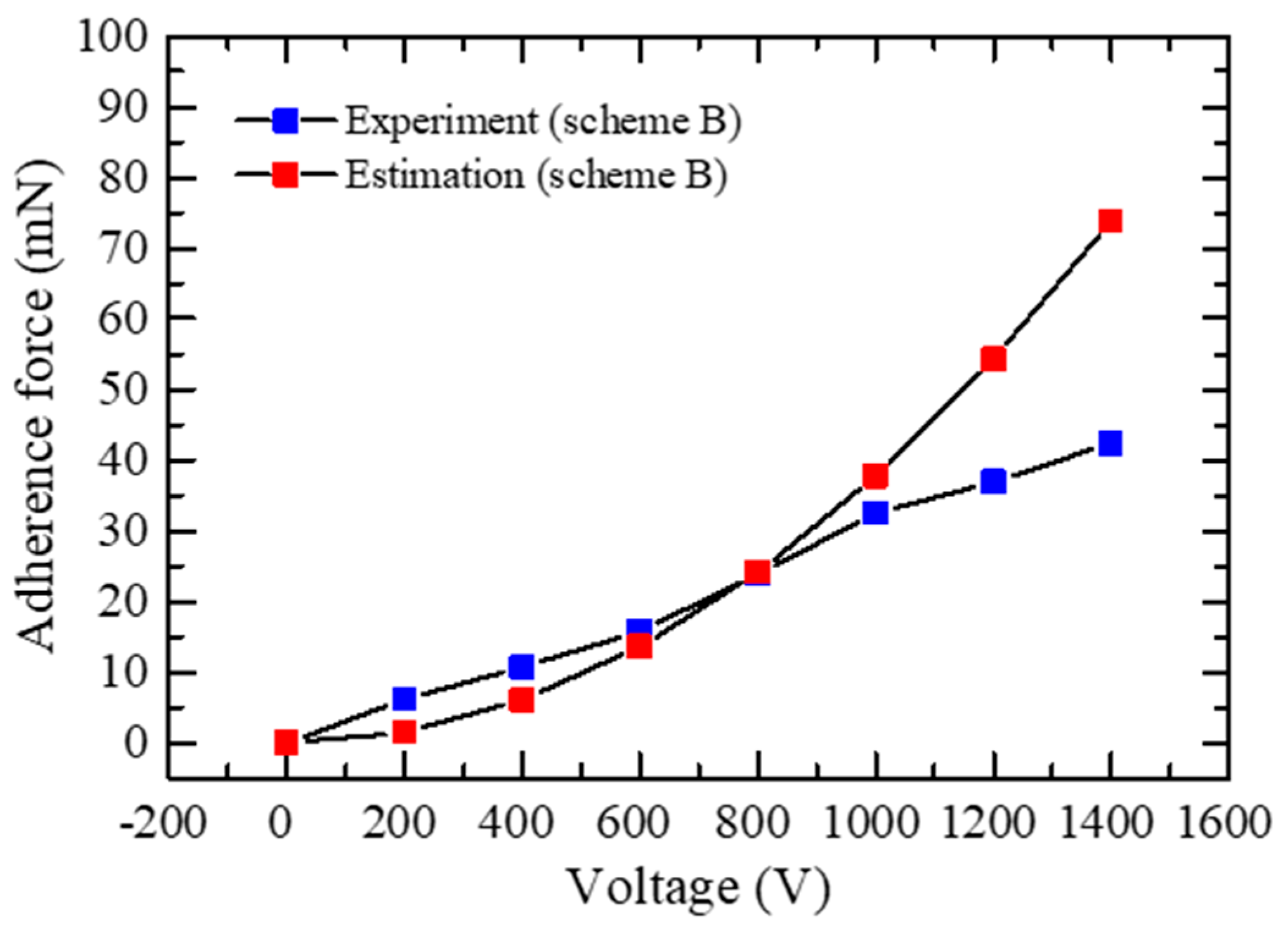
3.1. Performance of the Electrostatic Adhesion

To investigate the performance of the two electrostatic adhesion schemes experimentally, the linear actuator was tilted slowly and the adhesive forces were calculated indirectly by the maximum friction force that could prevent slippage caused by inclination. In the experiments, the maximum inclination angle θ without applied voltage reached 30°. Thus, the friction coefficient µ can be calculated as:
μ = tan θ 2 .
The actual adhesive force Fad can be estimated as:
F a d = G ( sin θ 2 μ cos θ ) μ m ,
where G is the gravitational acceleration.
Assume that fmax1µFad, the SIDM mode must be operated under the following condition:
F c < μ F a d .
It means that the impact force Fc generated by the rapid contraction of the PZT should be lower than the maximum static frictional force between the slider 1 and the copper electrode films. The magnitude of the impact force Fc is dependent on the amplitude, frequency, and duty ratio of the voltage applied to the PZT. Therefore, to drive the dual sliders effectively and independently at a relatively low impact force Fc, in this study, the maximum amplitude of the voltage was set as 60 V.
Based on Equations (9) and (10), the experimental adhesive forces with different applied voltages of the two schemes are drawn in Figure 6. As expected according to Equations (1) and (2), the scheme B can generate greater force than the scheme A. Thus, the scheme B was utilized in this study to generate electrostatic forces.
The plot in Figure 7 also shows the theoretical results calculated using Equation (2). The R2 of this model can reach 0.7297, which indicates that the model can accurately represent the relationship between applied voltages and adhesive forces on a certain device.

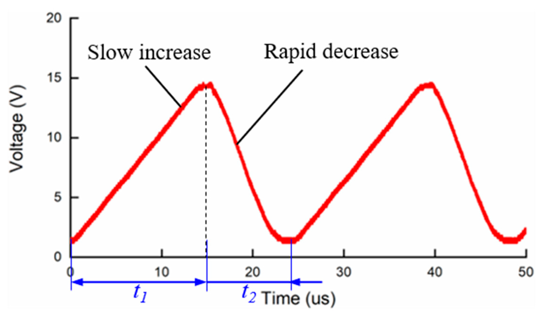
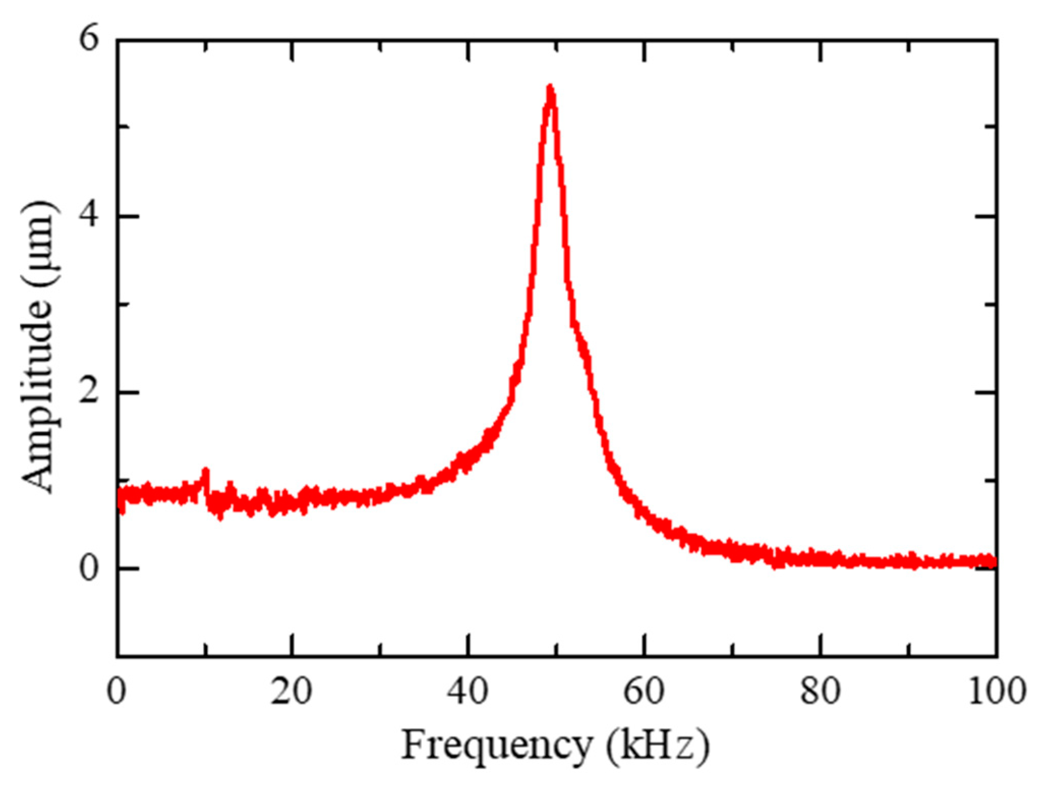
3.2. Dynamic Behavior of the PZT

The resonant frequency of the PZT can reach 261 kHz without applying loads. However, this value will decline significantly when connected to the slider 1 and the permanent magnet. Thus, the dynamic behavior of the PZT in the proposed actuator should be investigated experimentally in advance of the dual-slider positioning. The slider 1 was fixed and a 15 V peak-to-peak sine-wave swept from 0 Hz to 100 kHz was applied to the PZT. The displacement amplitude of the PZT was measured by an optical fiber displacement sensor (MTI instruments, MTI-2100). From Figure 8, the resonance frequency of the PZT was approximately 50 kHz, which ensures a wide bandwidth of around 40 kHz for both the IDM and SIDM modes.

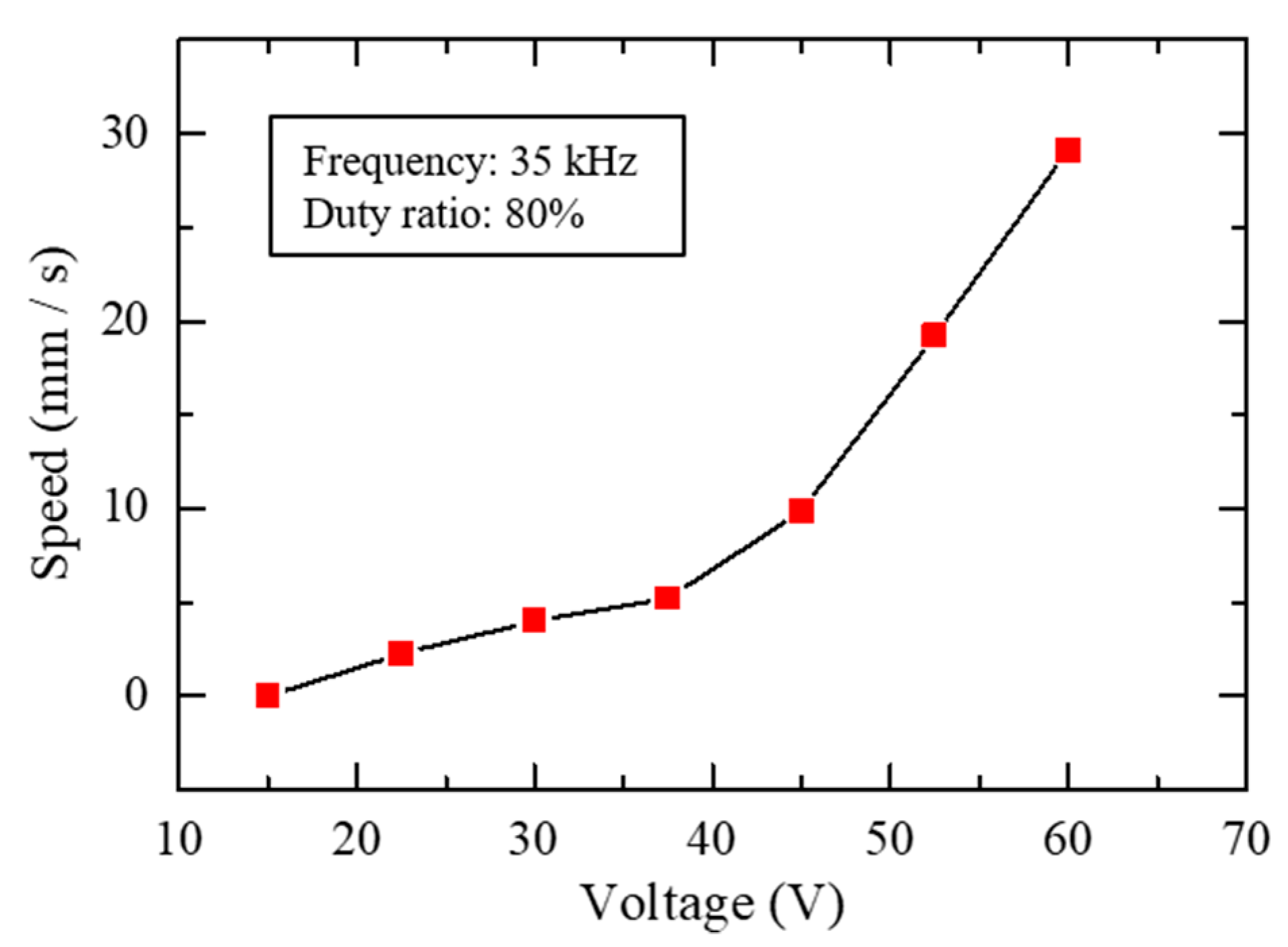
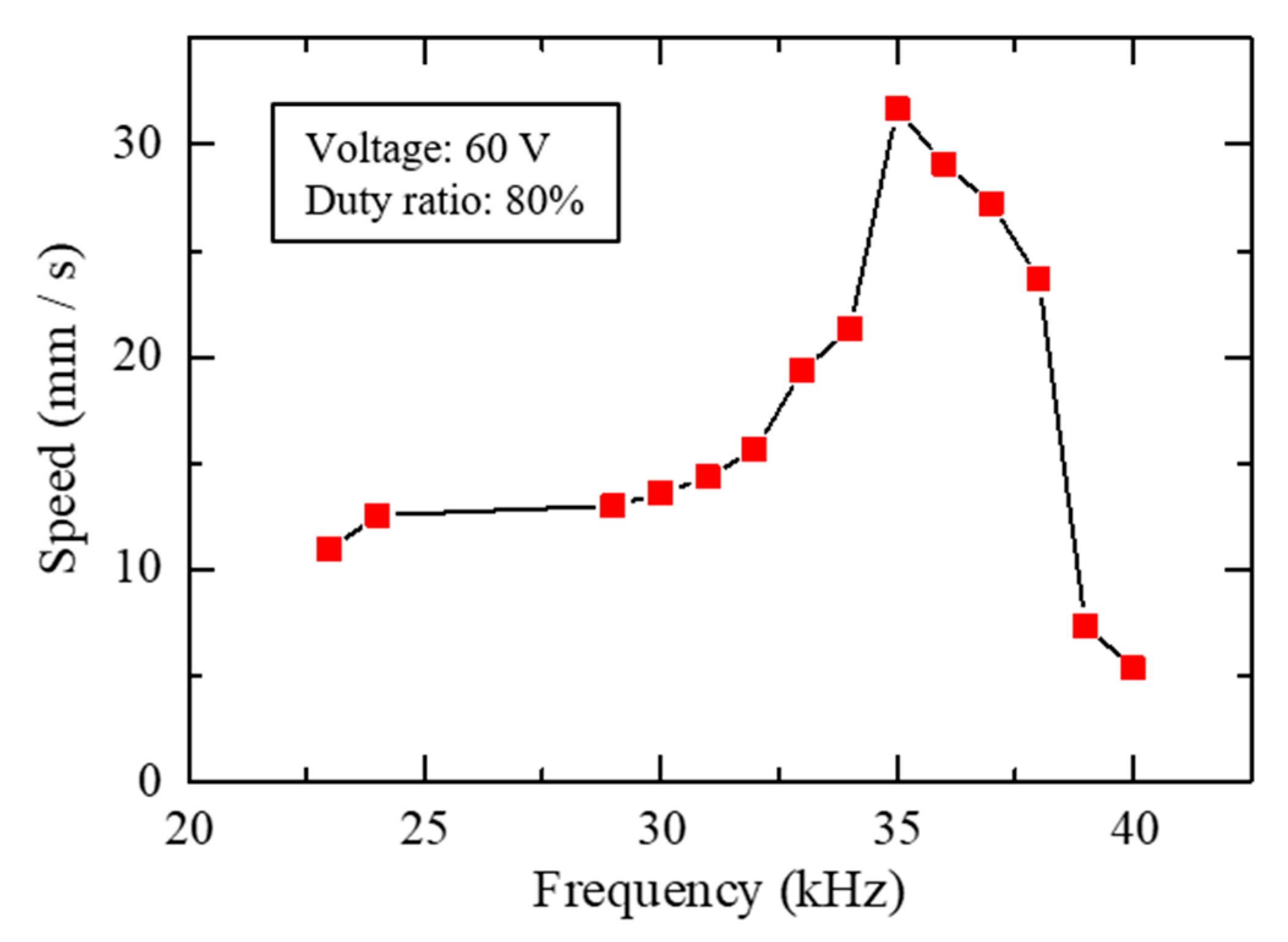
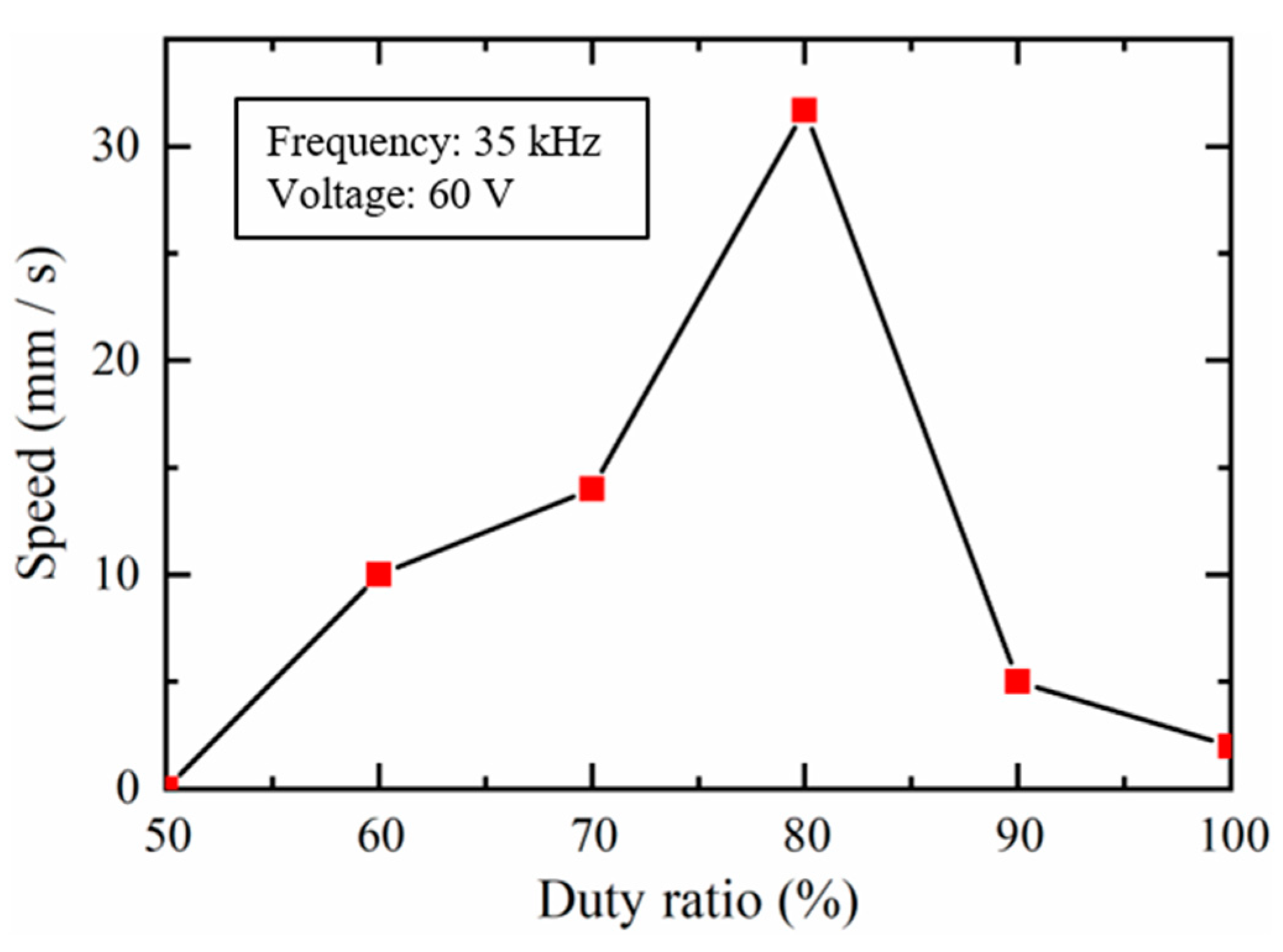
3.3. Driving Characteristics of the Slider 1

The prototype of the proposed actuator is shown in Figure 9. To detect the movement of the dual sliders, two mirrors (mirror 1 and mirror 2) were mounted on the ends of the sliders 1 and 2 respectively as measurement targets. A laser displacement sensor (MTI instruments, MTI LTS-050-10) was employed to measure the slider movement, as shown in Figure 10. Experiments were conducted to evaluate the influence of the input voltage on the driving characteristics of the dual sliders. Since the IDM and the SIDM are mechanisms based on inertia and friction force, their driving characteristics strongly depend on friction interfaces. The friction interfaces can be influenced by the manufacturing accuracy, assembly accuracy, and even indoor temperature or humidity. Therefore, in this study, all the experiments were repeated five times at different positions of the dual sliders, and the mean value was taken to show the driving performance of the sliders. For positioning the slider 1, no voltage was applied to the electrode films, and the actuator was operated in the IDM mode.
In Figure 11, the applied voltage was increased from 15 V towards 60 V with 35 kHz working frequency and 80% duty ratio. The slider 1 started to move at 22.5 V since the impact force of the PZT was not enough at smaller voltages. The moving speed of the slider 1 increased with the applied voltages and reached its maximum of 31.7 mm/s at 60 V. It is noted that two zones with a quasi linear evolution of the speed can be distinguished. The strongest influence of the phenomenon might be the hysteresis effect of the PZT and nonlinear behavior of the frictional force [22]. Additionally, in the minimum moving condition of 22.5 V, the positioning resolution of the slider 1 can be confirmed to be 60 nm, which was determined by one minimum step motion in the IDM mode.
The performance of the slider 1 at different frequencies was then analyzed with 60 V amplitude and 80% duty ratio. As shown in Figure 12, the moving speed increased with the frequency until 35 kHz due to the growing impact force. In other words, the maximum speed can be reached at 35 kHz. When the frequency surpassed 35 kHz, the system resonance started to influence the system and caused distortions to the waveform of the PZT displacement [19,20].
In addition, the influence of the duty ratio on the driving characteristics of the slider 1 was also investigated when the frequency was set as 35 kHz at 60 V. Since the driving characteristics of the dual sliders in the negative and positive directions were almost the same, only the driving characteristics in the positive direction were investigated in the study. From Figure 13, it can be seen that the slider 1 was still when the duty ratio was 50% and increased from 60% to 80%. The slider 1 reached its maximal speed at 80% duty ratio, but the speed began to decline when the duty ratio was larger than 80%. This was thought to be due to the distortions of the PZT displacement waveforms at high duty ratios, which has been reported in our previous research [20], including the waveform optimization of the PZT displacement.

3.4. Driving Characteristics of the Slider 2

In the positioning of the slider 1, the whole system including the IDM (including the slider 1, the PZT, and the permanent magnet) and the slider 2 is like a “self-moving” mechanism and slides freely along the base. During the IDM mode, crosstalk might be caused to the slider 2. Therefore, after the slider 1 is moved to its desired position, it should be fixed in order that the slider 2 can subsequently be positioned in the SIDM mode. For fixing the slider 1 and positioning the slider 2, two electrode films were charged to clamp the slider 1 on the V-shaped groove, which converted the IDM mode into SIDM mode. In this way, the slider 2 can be positioned independently while the slider 1 remained stationary. In the example of a zoom lens system, the zooming lens should be positioned first to get an appropriate field-of-view, followed by the positioning of the auto-focusing lens for obtaining a high-resolution image. Therefore, the sliders 1 and 2 can be used for positioning the zooming lens and the auto-focusing lens, respectively.
Like in the IDM mode, the moving speed of the slider 2 also varies at different voltages applied to the PZT in the SIDM mode, as shown in Figure 14, where the frequency was 9 kHz and the duty ratios were 20% and 80%, respectively. The slider 2 moved positively under 80% duty ratio and negatively under 20%. The slider 2 did not move until the voltage was higher than 15 V. Thereafter, the absolute value of the moving speed increased with the voltage amplitude at both 20% and 80% duty ratios.
To investigate the relationship between the voltage frequency and the moving speed of the slider 2, different driving frequencies were applied from 2 kHz to 18 kHz with 60 V amplitude and 80% duty ratio, as shown in Figure 15. It can be seen that the slider 2 did not move until the frequency surpassed 2 kHz and reached the maximum speed of 16 mm/s at 9 kHz. In addition, the moving speed decreased after the frequency reached 9 kHz. When the frequency reached 18 kHz, the severe distortion could suppress the speed to zero. Compared with the frequency of the maximal speed in the IDM mode, the frequency in the SIDM became lower. The most important reason is thought to be due to the different construction of the IDM and the SIDM. In the IDM mode, both the ends of the PZT (or its connections of the slider 1 and permanent magnet) were free. In the SIDM mode, one end of the PZT (or its connection of the slider 1) was fixed on the base, while the other end (or its connection of permanent magnet) was free. It can cause the effective driving frequency or natural frequency in the IDM mode two times as high as in the SIDM mode. Another reason is that the PZT was operated too many times near the resonance frequency at the beginning, which might lead to gradual degradation of the actuator performance. In fact, in the experiments, we found that it was easy to lead to the shedding of the permanent magnet from the PZT if the PZT was operated too many times near the resonance frequency.
The driving characteristics of the slider 2 at different duty ratios were also investigated in Figure 16. The moving speed shows the same trend as that of the slider 1, which was zero at 50% duty ratio and increased to its maximum at 80% duty ratio. Then, the moving speed decreased when the duty ratio became larger than 80%.
To investigate the positioning resolution of the slider 1, DC voltages with 0.6 V per step were applied to the PZT to generate high-resolution displacement, which can reach 13 nm, as shown in Figure 17. To achieve high resolution, the slider 2 can be slowly moved together with the permanent magnet due to static frictional force between the slider 2 and the permanent magnet. It means that the SIDM can only use an extremely small driving voltage and slow PZT expansion, which can achieve high positioning resolution as high as the PZT itself. In the IDM mode, the slider 1 is driven using impact step motions and its positioning resolution is determined by one step motion of the IDM. It means that the inertia force generated by the PZT should be large enough to overcome the static frictional force between the slider 1 and the electrode films, which might lead to large displacement in one step motion. The experimental results also indicate that the positioning resolution of the SIDM is higher than that of the IDM. After all, both the sliders 1 and 2 can be positioned with long motion ranges as well as high resolution.

3.5. Other Performance of the Dual-Slider Positioning

3.5.1. Crosstalk of the Slider 2 in the IDM Mode

As mentioned in the previous section, the whole system including the IDM and the slider 2 can be moved freely along the base during the IDM mode, and crosstalk might be caused in the slider 2 due to the friction force between the slider 2 and the permanent magnet. To investigate the positioning crosstalk of the slider 2 when positioning the slider 1, both the displacements of the sliders 1 and 2 were measured in the IDM mode. The amplitude, frequency, and duty ratio of the voltage applied to the PZT were set as 60 V, 35 kHz, and 80%, respectively, which can drive the slider 1 at its maximum speed in this paper. As shown in Figure 18, 0.086 mm crosstalk was caused in the slider 2 in the negative direction when the slider 1 moved 0.312 mm in the positive direction, which means that the positioning crosstalk of the slider 2 was approximately −27.6% of the movement of the slider 1. The result can be used for future closed-loop control of the dual sliders, and it is also confirmed that the slider 1 should be positioned first and the slider 2 should be moved to its desired position subsequently.

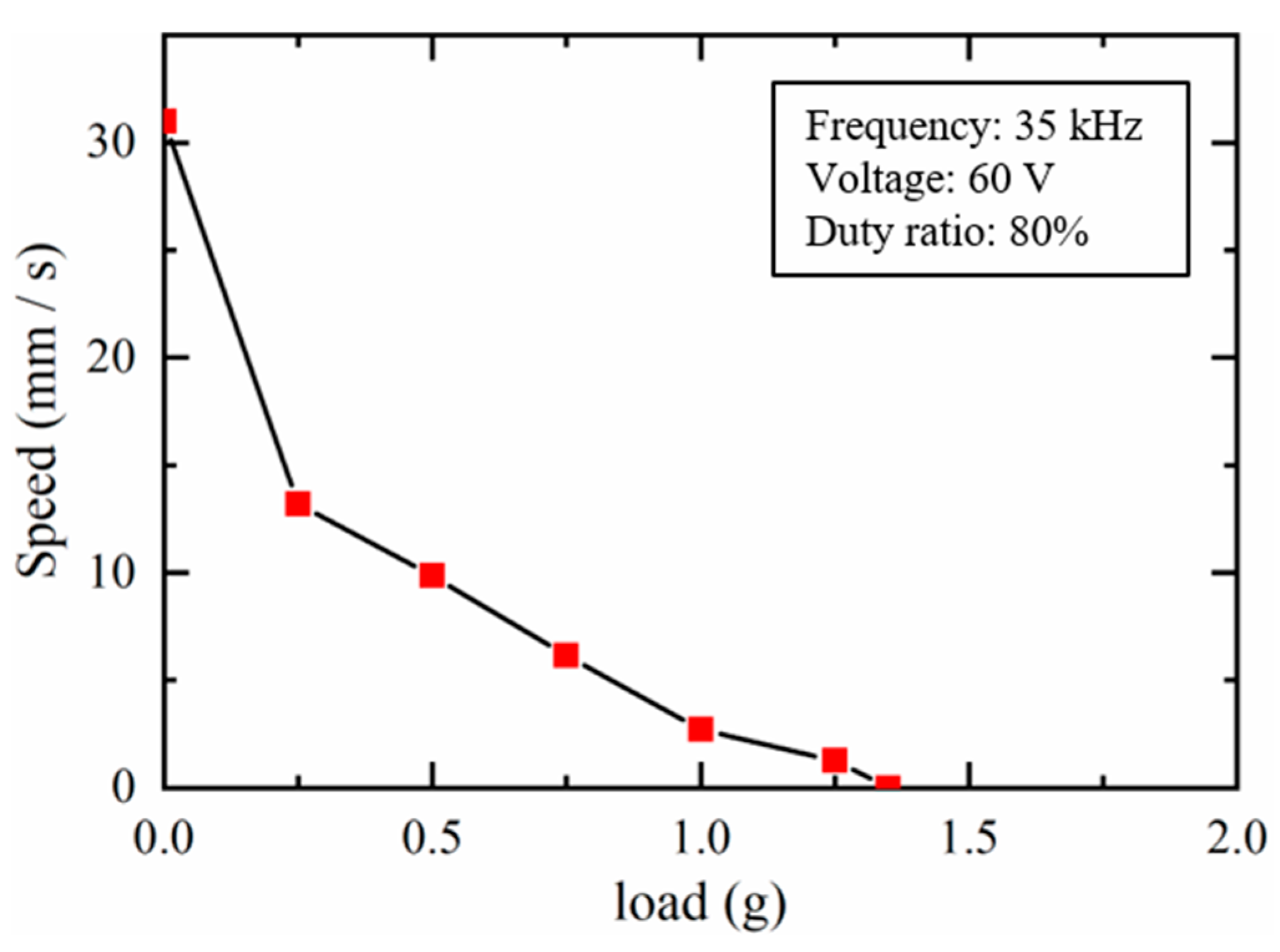
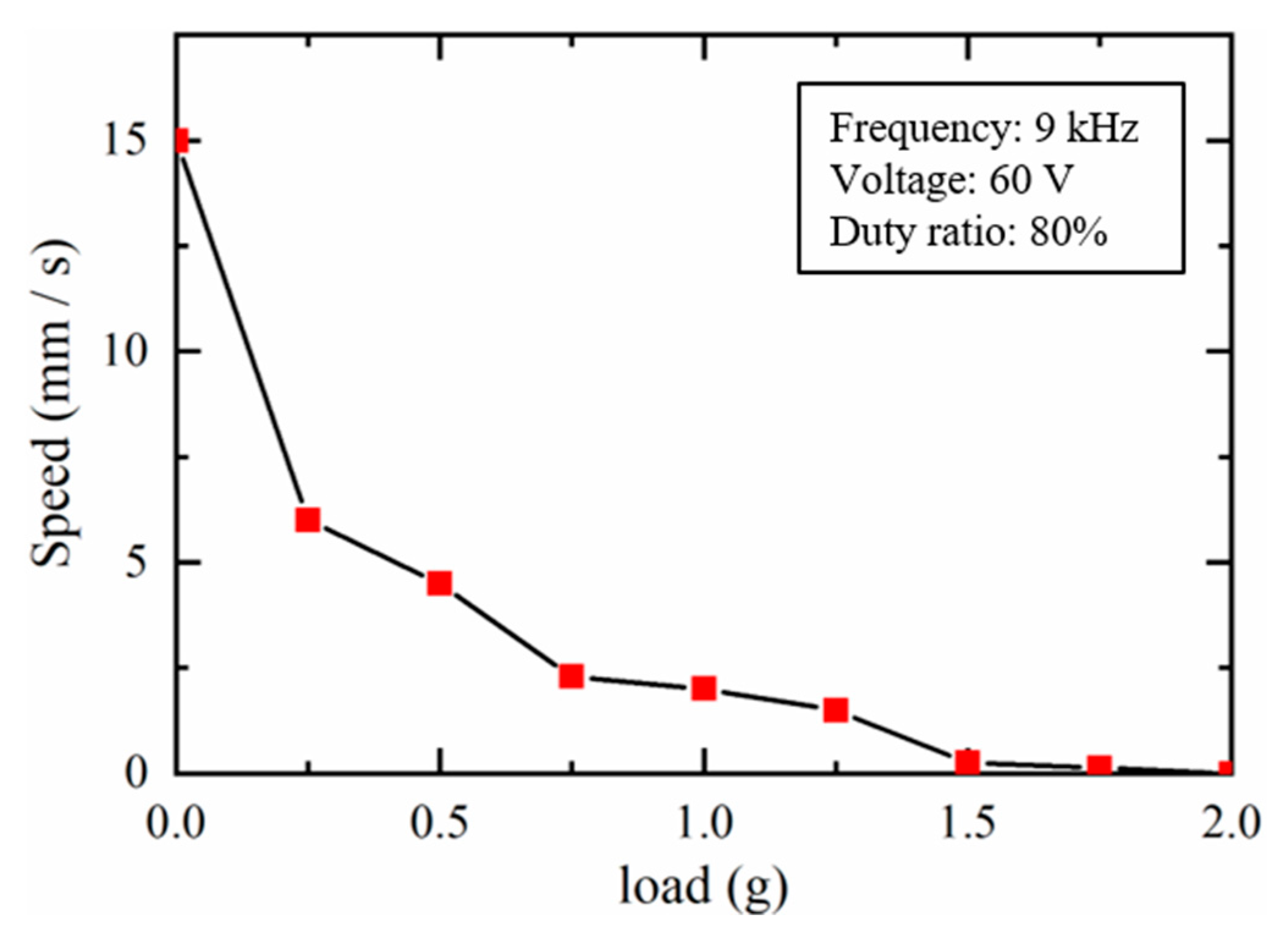
3.5.2. Load Capacity of the Dual Sliders

To investigate the load capacity of the dual sliders, experiments were carried out to verify the moving speeds of the dual sliders at different loads. Figure 19 shows the moving speeds of the slider 1 in the IDM mode when different loads were applied on the slider 1 in the Z-axis. The amplitude, frequency, and duty ratio of the applied voltage to the PZT were set as 60 V, 35 kHz, and 80%, respectively. When the load increased, the moving speed of the slider 1 declined and could not move at a load of 1.35 g. The same trend was also found in Figure 20, which shows the moving speeds of the slider 2 in the SIDM mode when increasing different loads. The amplitude, frequency, and duty ratio of the applied voltage to the PZT were set as 60 V, 9 kHz, and 80%, respectively. It can be seen that the slider 2 could not move when the load increased as high as 2.0 g. The results confirmed that the load capacity of the sliders 1 and 2 should be lower than 1.35 g and 2.0 g, respectively.
In the application of the positioning of micro-objects, it is important to carry relatively heavy micro-objects without excessive performance degradation. One approach is to design additional “carrying mechanisms” to carry the micro-objects. As shown in Figure 21, two carrying mechanisms, 1 and 2, are mounted on the sliders 1 and 2, respectively. The carrying mechanisms can slide along the base, and the friction interfaces between the base and the sliding mechanisms should be smooth enough. Therefore, the loads of the micro-objects can be transferred to the base, which may influence the actuator driving performance little.

3.5.3. “Slip-Slip” Performance of the Dual Sliders

In this paper, we explain the working principle of the dual sliders by “stick-slip” operation. We assume that one step motion of the applied saw-tooth voltage can generate a stick phase and a slip phase between the friction partners. Actually, in all the inertia drive mechanisms, “stick-slip” operation only exists at a specific frequency for a given duty ratio and amplitude of the applied voltage. As the frequency increases, the times t1 and t2 decrease simultaneously. Therefore, in the previous “stick” phase, the PZT expands faster because of the decreased t1. The inertia drive mechanisms are driven by dynamic frictional force instead of static frictional force. Therefore, slippage also occurs in the previous “stick” phase between the friction partners, and the operation mode becomes “slip-slip”. In the “slip-slip” operation, slippage occurs in both times t1 and t2, but the amount of forward slippage and the backward slippage is different, which can generate step motion to the sliders. Consequently, as the frequency increases, higher velocities and smooth movement can be achieved by the inertia drive mechanisms [14].

4. Discussion

The IDM and SIDM are two typical inertia drive mechanisms which have been reported in much literature. Both of them can position an object with a long motion range as well as high resolution. However, using only one IDM or SIDM for positioning multi-sliders is rarely found in the literature. The novelty of the proposed actuator is the combination of the IDM and SIDM by means of electrostatic adhesion. Due to a single PZT used in the actuator and thin-film structure of the electrostatic adhesion, the whole actuator can be made with a miniaturized size. Ultimately, by changing the operation modes between IDM and SIDM, two sliders can be positioned independently with long motion ranges as well as high resolution. The experimental results confirmed the driving characteristics of the dual sliders in long motion range positioning mode and high-resolution positioning mode. The positioning crosstalk as well as the load capacity of the dual sliders were also investigated experimentally. It was confirmed that crosstalk was caused to the slider 2 in the IDM mode. Therefore, the slider 1 should be moved to its desired position first. Subsequently, the slider 1 should be fixed in order that the slider 2 can be positioned in the SIDM mode. For the application of positioning relatively heavy micro-objects without excessive performance degradation, additional “carrying mechanisms” are proposed to carry the micro-objects, which can be mounted on the sliders but can slide along the base. This deserves further study and is currently under investigation.

5. Conclusions

In this paper, a miniaturized linear actuator based on electrostatic adhesion and inertia drive methods is proposed for positioning two sliders by a single PZT. The clamping conducted by the electrostatic adhesion is the key to converting two inertia drive methods of the IDM and SIDM. Unlike conventional electromagnetic clamping mechanisms, the proposed method requires less space and has lower installation complexity. A prototype was established to confirm the system feasibility. Both the motion ranges of the sliders 1 and 2 were 14 mm, corresponding to the geometrical dimensions of the actuator. Experiments were conducted for the evaluation of the dual slider driving characteristics. Results demonstrated that the maximum driving speeds of the sliders 1 and 2 were 31.7 mm/s and 16 mm/s, respectively, while the positioning resolution can remain as 60 nm and 13 nm, respectively. The small size, long motion range, and high precision make the proposed method a great solution for independently moving two sliders in miniaturized equipment, for example, micro zoom lens system with a zooming lens and an auto-focusing lens.

Author Contributions

Conceptualization, Y.P. and H.W.; methodology, Y.P., L.L. and X.S.; software, L.L.; validation, Y.P. and H.W.; formal analysis, X.S.; investigation, Y.Z.; resources, W.L.; data curation, X.S. and W.L.; writing—original draft preparation, X.S.; writing—review and editing, Y.P.; visualization, L.L.; supervision, Y.P.; project administration, Y.P.; funding acquisition, Y.P. All authors have read and agreed to the published version of the manuscript.

Funding

This research was funded by the Fundamental Research Funds for the Central Universities (No. 2018QNA224 and 2020XZA206), 2018 Qianjiang Talent Program of Zhejiang Province (No. QJC1802009), Jiangsu Province Natural Science Foundation of China (No. BK20160374), Natural Science Foundation of Zhejiang Province (No. LQ19C100002), MOE (Ministry of Education in China) Project of Humanities and Social Sciences (No. 19YJCZH126), and the “Double First-Class” Construction Fund of Zhejiang University.

Conflicts of Interest

The authors declare no conflict of interest.

References

  1. Li, X.; Yamamoto, A. A multi-slider linear actuator using modulated electrostatic attraction and inertia effect. In Proceedings of the 2016 11th France-Japan & 9th Europe-Asia Congress on Mechatronics (MECATRONICS)/17th International Conference on Research and Education in Mechatronics (REM), Compiegne, France, 15–17 June 2016; pp. 296–297. [Google Scholar]
  2. Nguyen, T.A.; Konishi, S. Characterization of sliders for efficient force generation of electrostatically controlled linear actuator. J. Micromech. Microeng. 2014, 24, 055012. [Google Scholar] [CrossRef]
  3. Peng, Y.; Cao, J.; Guo, Z.; Yu, H. A linear actuator for precision positioning of dual objects. Smart Mater. Struct. 2015, 24, 125039. [Google Scholar] [CrossRef]
  4. Hou, Y.; Zhang, Y.; Zhang, M.; Yu, H.; Peng, Y. Modeling and experimental verification of a dual-slider piezo-actuated linear motor. Instrum. Exp. Tech. 2019, 62, 876–880. [Google Scholar] [CrossRef]
  5. Ozeki, Y.; Hata, T.; Shibatani, K.; Nagai, F.; Mori, N.; Nakabayashi, Y.; Mitsugi, N.; Nakano, S.; Bhatia, V.; Gregorski, S.J. Miniature multiple-axes adaptive optics unit employing SIDMs and its application to an efficient green laser module. Konica Minolta Technol. Rep. 2009, 6, 82–87. [Google Scholar]
  6. Matsusaka, K.; Ozawa, S.; Yoshida, R.; Yuasa, T.; Souma, Y. Ultracompact optical zoom lens for mobile phone. In Proceedings of the SPIE-IS&T Electronic Imaging, San Jose, CA, USA, 20 February 2007; p. 650203. [Google Scholar]
  7. Zhang, Y.; Lu, T.-F.; Al-Sarawi, S. Formulation of a simple distributed-parameter model of multilayer piezoelectric actuators. J. Intell. Mater. Syst. Struct. 2016, 27, 1485–1491. [Google Scholar] [CrossRef]
  8. Li, J.W.; Chen, X.B.; An, Q.; Tu, S.D.; Zhang, W.J. Friction models incorporating thermal effects in highly precision actuators. Rev. Sci. Instrum. 2009, 80, 045104. [Google Scholar] [CrossRef]
  9. Peng, J.Y.; Chen, X.B. Modeling of piezoelectric-driven stick–slip actuators. IEEE/ASME Trans. Mechatron. 2010, 16, 394–399. [Google Scholar] [CrossRef]
  10. Hunstig, M.; Hemsel, T.; Sextro, W. Modelling the friction contact in an inertia motor. J. Intell. Mater. Syst. Struct. 2013, 24, 1380–1391. [Google Scholar] [CrossRef]
  11. Xia, H.; Han, L.; Pan, C.; Jia, H.; Yu, L. Simulation of motion interactions of a 2-DOF linear piezoelectric impact drive mechanism with a single friction interface. Appl. Sci. 2018, 8, 1400. [Google Scholar] [CrossRef] [Green Version]
  12. Pan, P.; Zhu, J.; Gu, S.; Ru, C. Development of stick-slip nanopositioning stage capable of moving in vertical direction. Microsyst. Technol. 2020, 26, 2945–2954. [Google Scholar] [CrossRef]
  13. Li, J.; Huang, H.; Morita, T. Stepping piezoelectric actuators with large working stroke for nano-positioning systems: A review. Sens. Actuators Phys. 2019, 292, 39–51. [Google Scholar] [CrossRef]
  14. Peng, Y.; Peng, Y.; Gu, X.; Wang, J.; Yu, H. A review of long range piezoelectric motors using frequency leveraged method. Sens. Actuators Phys. 2015, 235, 240–255. [Google Scholar] [CrossRef]
  15. Spanner, K.; Koc, B. Piezoelectric motors, an overview. Actuators 2016, 5, 6. [Google Scholar] [CrossRef]
  16. Hunstig, M. Piezoelectric inertia motors—A critical review of history, concepts, design, applications, and perspectives. Actuators 2017, 6, 7. [Google Scholar] [CrossRef] [Green Version]
  17. Higuchi, T.; Yamagata, Y.; Furutani, K.; Kudoh, K. Precise positioning mechanism utilizing rapid deformations of piezoelectric elements. In Proceedings of the IEEE Proceedings on Micro Electro Mechanical Systems, An Investigation of Micro Structures, Sensors, Actuators, Machines and Robots, Napa Valley, CA, USA, 11–14 February 1990; pp. 222–226. [Google Scholar]
  18. Okamoto, Y.; Yoshida, R. Development of linear actuators using piezoelectric elements. Electron. Commun. Jpn. Part III Fundam. Electron. Sci. 1998, 81, 11–17. [Google Scholar] [CrossRef]
  19. Yoshida, R.; Okamoto, Y.; Okada, H. Development of smooth impact drive mechanism (2nd report)-optimization of waveform of driving voltage. J. Jpn. Soc. Prec. Eng. 2002, 68, 536–542. (In Japanese) [Google Scholar] [CrossRef]
  20. Wang, J.; Chen, Y.; Peng, Y.; Song, X.; Zhang, Y.; Zhang, M. Waveform optimization of a two-axis smooth impact drive mechanism actuator. J. Intell. Mater. Syst. Struct. 2020. [Google Scholar] [CrossRef]
  21. Ha, J.-L.; Fung, R.-F.; Yang, C.-S. Hysteresis identification and dynamic responses of the impact drive mechanism. J. Sound Vib. 2005, 283, 943–956. [Google Scholar] [CrossRef]
  22. Fung, R.-F.; Han, C.-F.; Ha, J.-L. Dynamic responses of the impact drive mechanism modeled by the distributed parameter system. Appl. Math. Model. 2008, 32, 1734–1743. [Google Scholar] [CrossRef] [Green Version]
  23. Shao, Y.; Shao, S.; Xu, M.; Song, S.; Tian, Z. An inertial piezoelectric actuator with miniaturized structure and improved load capacity. Smart Mater. Struct. 2019, 28, 055023. [Google Scholar] [CrossRef]
  24. Wang, H.; Yamamoto, A.; Higuchi, T. A crawler climbing robot integrating electroadhesion and electrostatic actuation. Int. J. Adv. Rob. Syst. 2014, 11, 191. [Google Scholar] [CrossRef] [Green Version]
  25. Wang, H.; Yamamoto, A. Analyses and solutions for the buckling of thin and flexible electrostatic inchworm climbing robots. IEEE Trans. Rob. 2017, 33, 889–900. [Google Scholar] [CrossRef]
Figure 1. Configuration of the dual-slider linear actuator.
Actuators 09 00114 g001
Figure 2. Two schemes for electrostatic adhesion generation: (a) scheme A, (b) scheme B.
Actuators 09 00114 g002
Figure 3. A saw-tooth voltage applied to the piezoelectric element (PZT).
Actuators 09 00114 g003
Figure 4. The impact drive mechanism (IDM) mode for positioning the slider 1. (a) Initial position of the PZT; (b) Slow expansion of the PZT; (c) Rapid contraction of the PZT.
Actuators 09 00114 g004
Figure 5. The smooth impact drive mechanism (SIDM) mode for positioning the slider 2. (a) Initial position of the PZT; (b) Slow expansion of the PZT; (c) Rapid contraction of the PZT.
Actuators 09 00114 g005
Figure 6. Generated adhesive forces of different wiring schemes.
Actuators 09 00114 g006
Figure 7. Adhesive force by experiment versus adhesive force by estimation.
Actuators 09 00114 g007
Figure 8. Frequency response of the PZT.
Actuators 09 00114 g008
Figure 9. Prototype of the proposed actuator.
Actuators 09 00114 g009
Figure 10. Experiment setup for the dual-slider driving characteristics.
Actuators 09 00114 g010
Figure 11. Driving characteristics of the slider 1 at different voltages.
Actuators 09 00114 g011
Figure 12. Driving characteristics of the slider 1 at different frequencies.
Actuators 09 00114 g012
Figure 13. Driving characteristics of the slider 1 at different duty ratios.
Actuators 09 00114 g013
Figure 14. Driving characteristics of the slider 2 at different voltages.
Actuators 09 00114 g014
Figure 15. Driving characteristics of the slider 2 at different frequencies.
Actuators 09 00114 g015
Figure 16. Driving characteristics of the slider 2 at different duty ratios.
Actuators 09 00114 g016
Figure 17. Actuation resolution of the SIDM mode.
Actuators 09 00114 g017
Figure 18. Crosstalk of the Slider 2 in IDM Mode.
Actuators 09 00114 g018
Figure 19. Load Capacity of the slider 1.
Actuators 09 00114 g019
Figure 20. Load Capacity of the slider 2.
Actuators 09 00114 g020
Figure 21. One approach to carry relatively heavy micro-objects.
Actuators 09 00114 g021
Publisher’s Note: MDPI stays neutral with regard to jurisdictional claims in published maps and institutional affiliations.

