1. Introduction
One main trend of the fourth industrial revolution, better known as Industry 4.0, is advanced robotics, as proposed in [
1]. Collaborative robotics belongs to this trend. It has been conceived to increase human–machine collaboration: the individual competency and ability of the human operator is combined with the accuracy and repeatability performance of the robot. Unlike traditional industrial robots, collaboration expects that the operator and the robot will share the same workspace. Hence, safety must be the first requirement for human–robot coexistence and interaction. According to the specifications and guidelines defined in [
2], safety is addressed by constructors through proper hardware (robots with a light structure, without sharp edges, covered by soft materials, equipped with sensors able to immediately detect accidental impacts), proper software (with the ability to set the operative speed and the maximum exerted power and force, inhibition of work planes or spaces, and slow start procedure) and lower performance than traditional industrial robots (small value of the maximum operative speed and a low pay load).
End effectors are included in the safety concept. Among the wide range of available end effectors, certainly, soft graspers reduce the risk of hazards and injuries, eventually caused to the human operator, because they are equipped with soft actuators. As reported in the scientific literature [
3,
4,
5,
6,
7,
8,
9], researchers have developed several kinds of soft actuators, different on the basis of the adopted technologies and working principles: the jamming of granular material, shape memory polymers, shape memory alloys, electroactive polymers, conductive elastomers, and electrorheological and magnetorheological fluids.
Pneumatic soft actuators represent another kind of feasible solution for the end effectors of collaborative robotics: they are intrinsically safe for the compliant structure and the material they are made of; they provide for variable stiffness [
10] and for the development of bioinspired adaptive and flexible devices [
11]; they show a high power-to-mass ratio, high versatility and low cost. In order to grasp objects of different shapes and sizes, bending pneumatic soft actuators have been developed: they show the common characteristic of being made of soft material whose stiffness is not uniformly distributed. In particular, it is possible to distinguish two classes of bending actuators. The first one is represented by actuators realized by a deformable tube, not necessarily with a circular section, totally made of elastic material and with a suitable shape [
12,
13,
14,
15]. Moreover, the tube can be divided into two or more chambers: the difference in pressure in the chambers provides for a bending motion [
16,
17]. Other solutions involve asymmetrical tubes: the thickness is not uniform along the perimeter of the tube [
18], or, with a uniform thickness, one edge of the tube shows a profile with asymmetric bellows [
19,
20,
21,
22]. In the last solutions, the thicker edge remains at the same length while the thinner one increases its length, providing for the bending; bellows increase the flexibility and the range of deformation. Finally, air chambers can be obtained between two adjacent films with different stiffnesses that realize the tube; the swelling of the chambers provides for the bending [
23]. The second class is represented by actuators made of a deformable tube externally reinforced by a rigid structure, quite similar to the McKibben pneumatic muscle [
24], also adopted for powering assistive devices [
25,
26]. Bending can be obtained by mounting in parallel two McKibben muscles, with different braided angles, [
27]. Otherwise, the braided shell, with a constant braided angle, can be wrapped around a tube with a non-constant rectangular section, as a wedge [
28]; it is possible to adopt the same solution around a tube with a constant rectangular section, or with a semi-circular section in which a surface is covered by an inextensible material [
29,
30,
31]. Both classes provide for the bending of all soft joints in the same direction, like the behavior of the human finger.
However, some industrial applications could require graspers whose shape must be kinematically mirrored to the shape of the object to be grasped: it is the case for fast pick-and-place operations for lightweight and/or fragile objects whose shapes can show curvatures in opposite directions (i.e., concave and convex) or undercuts and where a form coupling between the grasper and the object should be preferred. In such operations, while the collaborative robot performs fast and precise motion, the grasp must be, at the same time, soft and tight.
The actuator proposed here belongs to the second class, with the property of being intrinsically safe and able to kinematically mirror the shape of the object to be grasped. It is an underactuated actuator made of an inner hyper-elastic tube wrapped in an inextensible gauze with cuts. When compressed air is blown, cuts provide for the bending of it, avoiding axial elongation. The actuator shows similar characteristics to the actuator in [
30], although the fabrication process and the adopted solution for controlling the magnitude of the bending radius of the latter are very different. The first requires a multi-step molding process to include and anchor in the flexible tube all the fiber reinforcements, placed in the form of a layer of fibers and a hand-wound fiber reinforcement along the entire length of the tube; the combination of the fiber reinforcement and the tube provides for the bending of the actuator. The second requires the adoption of an additional external sleeve to restrict covered parts of the reinforced tube from bending: by adjusting the distance between two consecutive sleeves, the magnitude of the bending is controlled; moreover, to constrain radial expansion on flat surfaces, the actuator requires the incorporation of passive rigid elements between the tube and the external sleeve. Differently, the actuator proposed here requires a simple tube externally reinforced by a single gauze that determines the bending and the magnitude of the bending radius, according to the parameters of the cuts, and avoids unwanted deformations without the adoption of additional components.
To predict the bending behavior of the actuator proposed here and to design it for grasping an object whose geometry is known a priori, a qualitatively predictive formula was devised. A similar route was followed in [
32], where soft bending actuators are adopted as fingers for a soft pneumatic glove for hand rehabilitation. Each joint of a finger is made of adjacent air chambers, whose number depends on the range of motion of the joint. The inflating pressure causes a bulge in the lateral wall of the chambers; the contact forces between the lateral walls of two deformed adjacent air chambers provides for the bending of the chamber pair. To predict the bending magnitude, two formulas have been devised, on the basis of two analytical models: the first formula addresses the relationship between the inflating pressure and the geometrical parameters of the lateral wall of the air chamber, including the bulge height; then, a second formula addresses the relationship between the bending moment–angle curves and the inflating pressure, considering the geometry of the lateral wall, the geometry of the junction zone between two adjacent chambers and the expanding of it due to the stress concentration. Differently, the actuator proposed here has only one air chamber (the tube) and the bending involves only the free portion of the actuator under the cuts and depends on the pressure value and the geometrical parameters of each cut. Moreover, the devised formula is not based on an analytical model but on a validated finite element model of the actuator, and it provides a relationship among the bending angle, the geometrical parameters of the cut and the pressure. For the production of the flexible inner component, the proposed actuator requires a simpler mold (a simple non-reinforced tube must be manufactured) whose shape is independent of the curvature (concave or convex) of the actuator and of the wanted bending magnitude, as could occur for the abovementioned actuators. Finally, the actuator here presented can bend in opposite directions.
In addition to the previous topics, the novel aspect of the proposed actuator is in its conceptual design: a hyper-elastic tube, that can be commercially available in different sizes and lengths, can be inserted into a partially rigid external structure with cuts placed with precision, according to a formula developed for their design, and is easy to realize, on the basis of the shape of the object to be grasped.
Starting from the conceptual idea of the proposed actuator and due to its nonlinear behavior, a finite element model of the actuator and its validation are presented; then, by several simulations carried out with the validated finite element model, the derivation of a qualitatively predictive formula (to be used as a design tool in substitution for the finite element model) for the bending behavior is described; finally, based on the formula, the design methodology is detailed. The effectiveness of the design methodology is demonstrated in a practical application: the design of an actuator whose shape kinematically mirrors the shape of a light bulb.
2. Development of the Numerical Model
2.1. The Conceptual Idea of the Actuator
The actuator has been conceived to be made of an inner hyper-elastic silicone rubber tube wrapped in a polyamide inextensible square-meshed gauze. One end of the tube is closed and nondeformable; the other one provides for the inlet/outlet of the compressed air. When the tube is inflated, the external gauze must contain the radial and axial expansions of the tube and guide the bending movement of it through appropriate circumferential cuts that realize the joints of the actuator, similar to those of the human finger. The bending of each joint depends on the circumferential extension and the axial length of the cut. Each cut is made on planes placed perpendicularly to the symmetry axes of the tube and involves only a sector of the total circumferential envelope of the gauze.
The functional parameters (the air pressure value and the number of the cuts) and the geometrical parameters (the external diameter and the wall thickness of the tube, the axial and the circumferential lengths of the cuts and their positions along and around the tube) determine the underactuated kinematics of the actuator, whose behavior is nonlinear: the relationships among the abovementioned parameters, the constitutive law of the hyper-elastic material of the tube and the high deformations in correspondence of the joints are nonlinear. Friction between the tube and the gauze could occur.
2.2. The Numerical Model
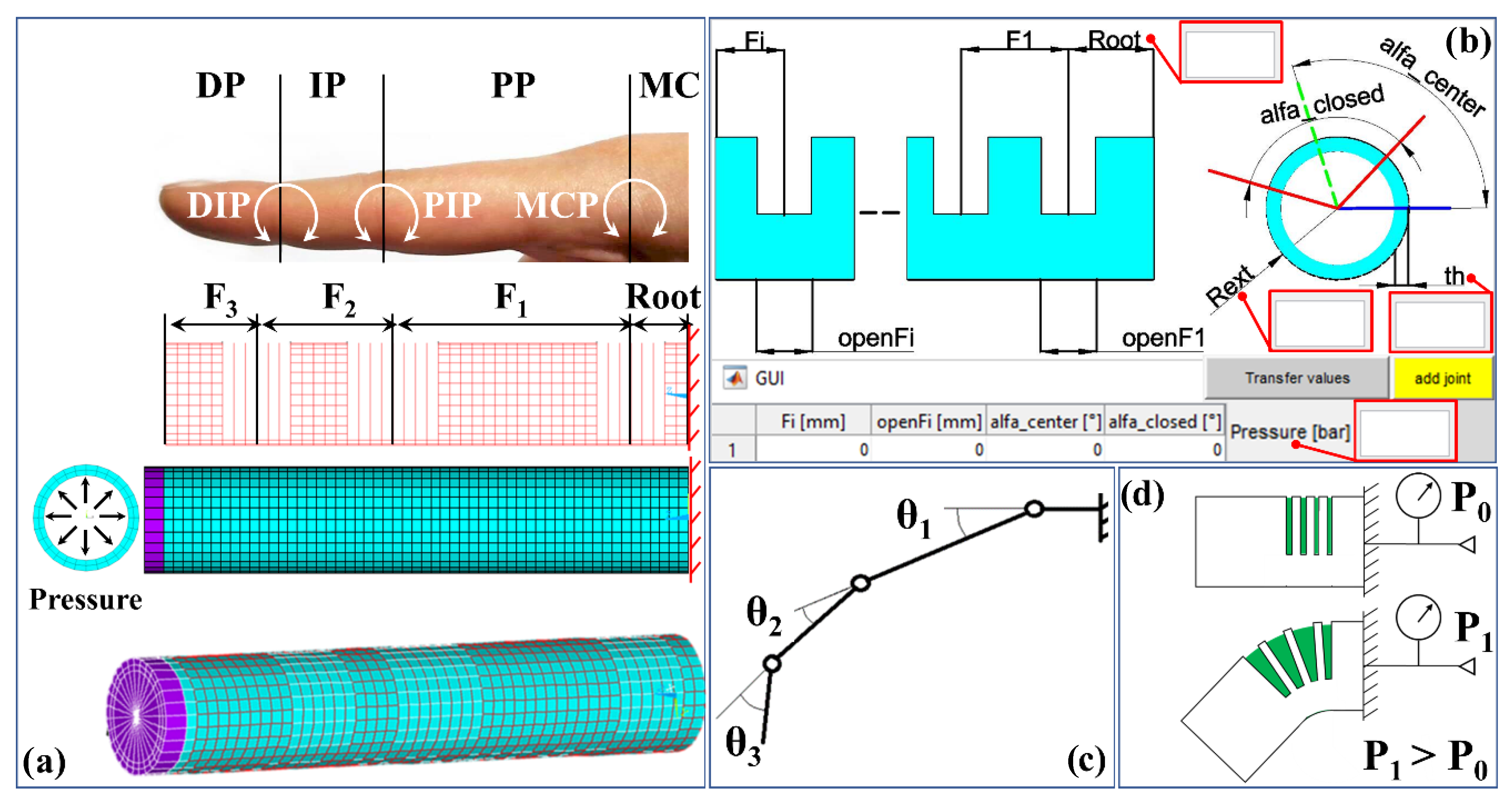
Due to the nonlinearities, it is difficult to predict the behavior of such actuator, according to different sets of parameter values, unless several prototypes are realized. Hence, a three-dimensional parametric numerical model, based on the finite element method (FEM), was developed. Since anthropometric data of the human finger are available in the literature, the FEM model, hereinafter called the model, was built as a bioinspired model of the index finger in which four parts can be distinguished: the metacarpal (MC), the proximal phalanx (PP), the intermediate phalanx (IP) and the distal phalanx (DP), indicated in the model as Root, F1, F2 and F3, respectively, as shown in
Figure 1a. Moreover, the metacarpophalangeal (MCP), the proximal interphalangeal (PIP) and the distal interphalangeal (DIP) joints are placed between the two respective phalanxes.
The construction of the model was carried out using software developed in the Mathworks
® Matlab environment. A graphical user interface (GUI), shown in
Figure 1b, was created in order to input the following parameters:
- -
Fi: the length of the i-th phalanx, measured in mm.
- -
openFi: the axial length of the i-th cut, measured in mm.
- -
alfa_center: in correspondence of the i-th cut region (i.e., i-th joint), the angular position of the center of the uncut sector of the gauze, measured in °.
- -
alfa_closed: in correspondence of the i-th cut region, the angular extension of the uncut sector of the gauze, measured in °. It is always considered symmetrical with respect to the alfa_center value.
- -
Rext: the external radius of the inner hyper-elastic tube, measured in mm.
- -
Root: the length of the metacarpal or, more generally, of the initial part of the actuator attached to a support, measured in mm.
- -
th: the thickness of the inner hyper-elastic tube, measured in mm.
- -
Pressure: the maximum value of the compressed air pressure in the actuator, measured in bar.
Given the values of the parameters and the lowest dimension of the finite element, an additional parameter of the model, the software writes a script file in the APDL language of the commercial code Ansys, Academic Release 19.2, to be run in the Ansys environment.
The wall thickness of the tube is divided into two layers of elements; hence, perpendicularly to the symmetry axis of the model, three concentric sets of nodes are created, starting from the outer part of the tube towards the inner one. In the circumferential direction, for each set, nodes are equally spaced along a circle: the chosen dimension of the element and the external radius of the tube provide for the number and the angular distance of the nodes. In the axial direction, the chosen dimension of the element and the dimensions of
Fi and
Root provide for the number of planes in which each set of nodes is constructed. With reference to
Figure 1a, three sets of elements are used: two, made of brick elements (SOLID185, Ansys Library), are used to model the tube and the closed end of it, shown in cyan and violet, respectively; the remaining one, made of truss elements (LINK180, Ansys Library), is used to model the external gauze, shown in red. To simplify the model, the gauze and the tube are considered glued together. To avoid creating a contact problem, the elements of the gauze share the same nodes of the outer faces of the elements of the tube.
According to the results of previous studies [
33,
34], the hyper-elastic silicone rubber material is modelled by two first-order coefficients (C
10 = 0.0694 MPa and C
01 = 0.0628 MPa, ν = 0.46) of the Mooney–Rivlin formulation; the nondeformable closed end is modelled as a linear isotropic material, with the mechanical properties of aluminum (E = 70000 MPa; ν = 0.33); the gauze material is modelled as linear isotropic, with the mechanical properties of polyamide (E = 2000 MPa, ν = 0.10). A fixed constraint is applied at the end in correspondence of the
Root. Pressure is applied to the internal faces of the inner elements of the tube. The gravity effect was neglected. The Newton–Raphson method was implemented to perform the nonlinear analysis: pressure was applied from zero to the
Pressure value, according to a time step automatically chosen by the FEM code.
The first implementation of the model was addressed to iteratively achieve the optimal set of parameters to reproduce the behavior of the male index finger. The values of
F1,
F2 and
F3 were directly set to respect the anthropometric data of the average dimensions of the male index finger [
35], reported in
Table 1.
On the contrary, with reference to
Figure 1c, several simulations were carried out to determine the proper values of
openF1,
openF2,
openF3,
alfa_closed (same value for all the joints) and
Pressure to satisfy the following relations [
29]:
The behavior of a joint is shown in
Figure 1d: given the geometry and the number of the cuts, the value of each angle θ depends on the value of Pressure. An increase in Pressure provides for an increase in θ.
Since it does not affect the behavior of the finger,
Root was set equal to 10 mm, to reduce the number of nodes and the computing time;
Rext was set equal to 10 mm;
th was set equal to 2 mm, on the basis of considerations later described about the experimental prototype. Since the bending of the three joints occurs in the same plane,
alfa_center was fixed as equal for all joints. The element size was previously evaluated in terms of comparison among results obtained with models built with 1 and 2 mm element sizes. The results were similar. For this reason, the element size has been set equal to 2 mm. The model counts 4286 nodes and 5110 elements. The overall achieved set of parameters is reported in
Table 2.
2.3. The Experimental Prototype
The tube is made of the silicone rubber Dow Corning XIAMETER RTV-4250-S (cured for 24 h at 23 °C: Hardness Shore A 25; tensile strength, 7.0 MPa; elongation at break, 850%; tear strength, 23 kN/m; linear shrinkage <0.1%), a bi-component material made of a high-viscosity base (26,000 mPa s) and a curing agent (140 mPa s), with a mass ratio equal to 10:1, respectively. This silicone rubber was chosen on the basis of the expertise collected during previous research activities [
33,
34,
36,
37,
38,
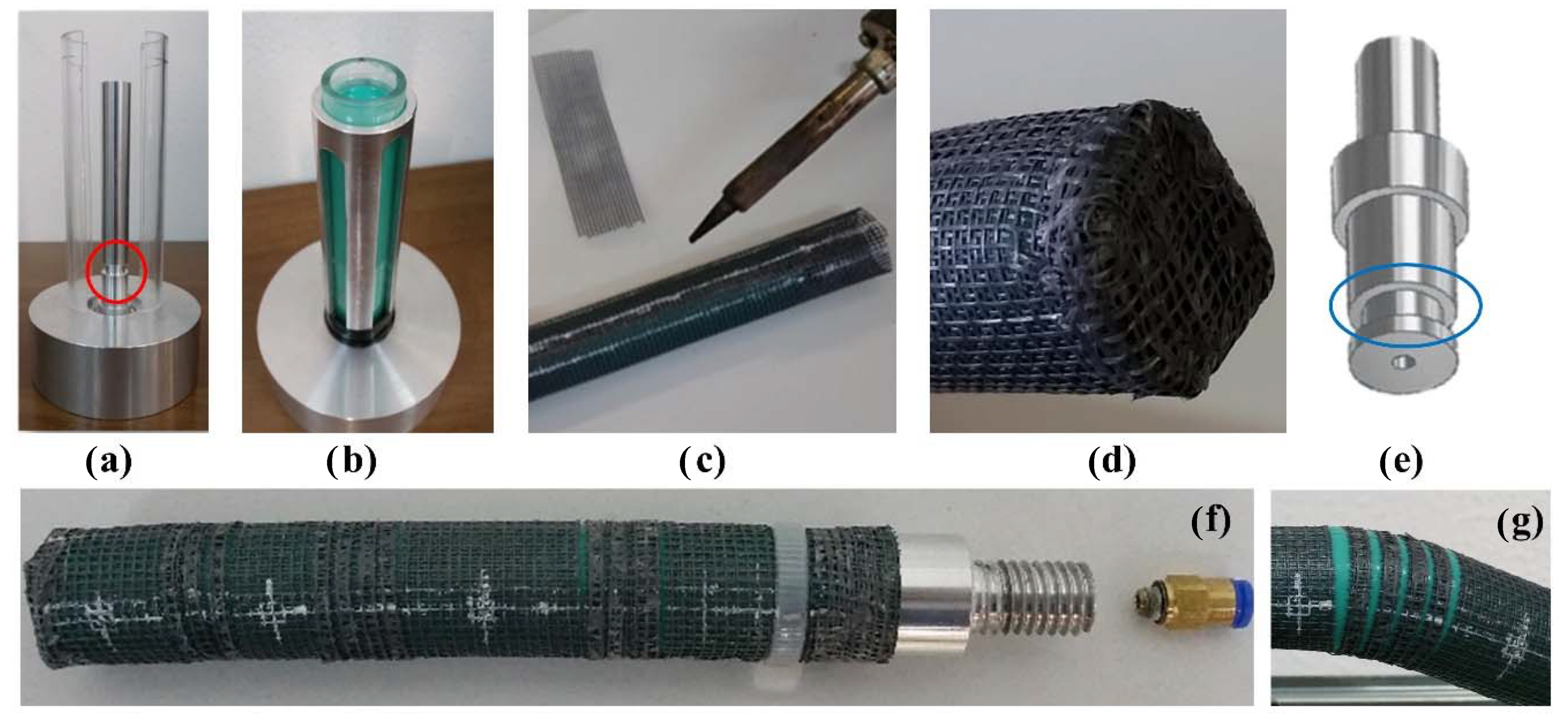
39]. To make the cylindrical shape, the high-viscosity mixture of the two components must be poured into a mold; the catalyzation process takes about 8 h at 20 °C. The designed and prototyped mold is made of a cylindrical base support, a core in aluminum, two semi-tubular shells in polycarbonate and a centering tube to guarantee the coaxiality among the core and the two shells (
Figure 2a).
A vibrating plate was adopted to remove possible inclusions of air bubbles inside the mixture. Such inclusions can be observed, through the shells, by windows realized in the centering tube. To obtain the closed end of the tube, the molded silicone rubber must exceed the height of the top end of the core of about 4 mm (
Figure 2b). A circumferential groove, with a rectangular section, was realized in the lower part of the core (red circle in
Figure 2a): it results in a protrusion on the inner surface of the tube, to ensure the mechanical and pneumatic seal, as later described in the assembly operation of the actuator. The overall height of the tube is equal to 125 mm, the external diameter being equal to 20 mm. The wall thickness is equal to 2 mm, suggested by the silicone rubber datasheet as the lower feasible thickness for a mold. A piece of 150 × 150 mm of the polyamide gauze was used with a square mesh size equal to 2 mm and a thickness equal to 0.25 mm. Before the wrapping, one edge of the gauze was glued to the tube, along the axial direction; then, the gauze was twice rolled up to the tube: a strict adherence between the tube and the gauze must be assured. The opposite edge of the gauze was welded to the underlying layers of it, along the entire axial length of the tube, in correspondence of the glued side (
Figure 2c). The welded line was placed in the lower part of the actuator since cuts will not be carried out in this sector. Gauze was also welded in correspondence of the closed end of the tube to act like a plug (
Figure 2d). Scissors were adopted to carry out the cuts in order to satisfy the values reported in
Table 2. The stacked layers corresponding to the cuts were welded to avoid possible slipping. An aluminum plug (
Figure 2e), equipped with a pneumatic fitting for the air inlet/outlet, is placed at the open end of the prototype (
Figure 2f): a pneumatic seal is guaranteed by the coupling of the inner rectangular protrusion of the tube with the groove (blue ellipse) realized in the plug; a mechanical seal is guaranteed by an external plastic belt that fixes the gauze, the tube and the plug. A detail of the cuts, when the tube is inflated, is shown in
Figure 2g. The mass of the tube with the gauze is equal to 0.013 kg; the overall mass of the prototype is equal to 0.08 kg.
2.4. The Experimental Validation of the Numerical Model
Validation was carried out by the comparison of the experimental and numerical values of the angles θ1, θ2 and θ3, depending on the pressure value. A test bed, made of aluminum commercial profiles (30 × 30 Rexroth Bosch Group) mounted to realize a portal structure was realized; a manometer (Nuova Fima DN-100), with a resolution of 0.05 bar, was adopted for the pressure measurement; a precise pressure regulator (SMC IR-1000) completed the test bed. The end of the actuator with the aluminium plug was fixed, with a couple of nuts, to a bracket rigidly fixed to the test bed. The actuator sticks out from the test bed. A 4 mm external diameter polyurethane tube (SMC Corporation) was adopted for the air inlet/outlet. Tests were carried out starting from zero pressure, with an increase of 0.10 bar, until the value of 2.30 bar, corresponding to the closure of the finger, over the conditions expressed in (1)–(3). About 5 s was taken to manually adjust the pressure regulator in order to reach the next pressure step. When each pressure step was reached, about 10 s was spent to check if residual deformations, due to the viscoelastic behavior of the silicone rubber, occurred. Then, a picture of the actuator was taken. No residual deformations were ever recorded. The time between the reaching of the two consecutive pressure steps was about 30 s.
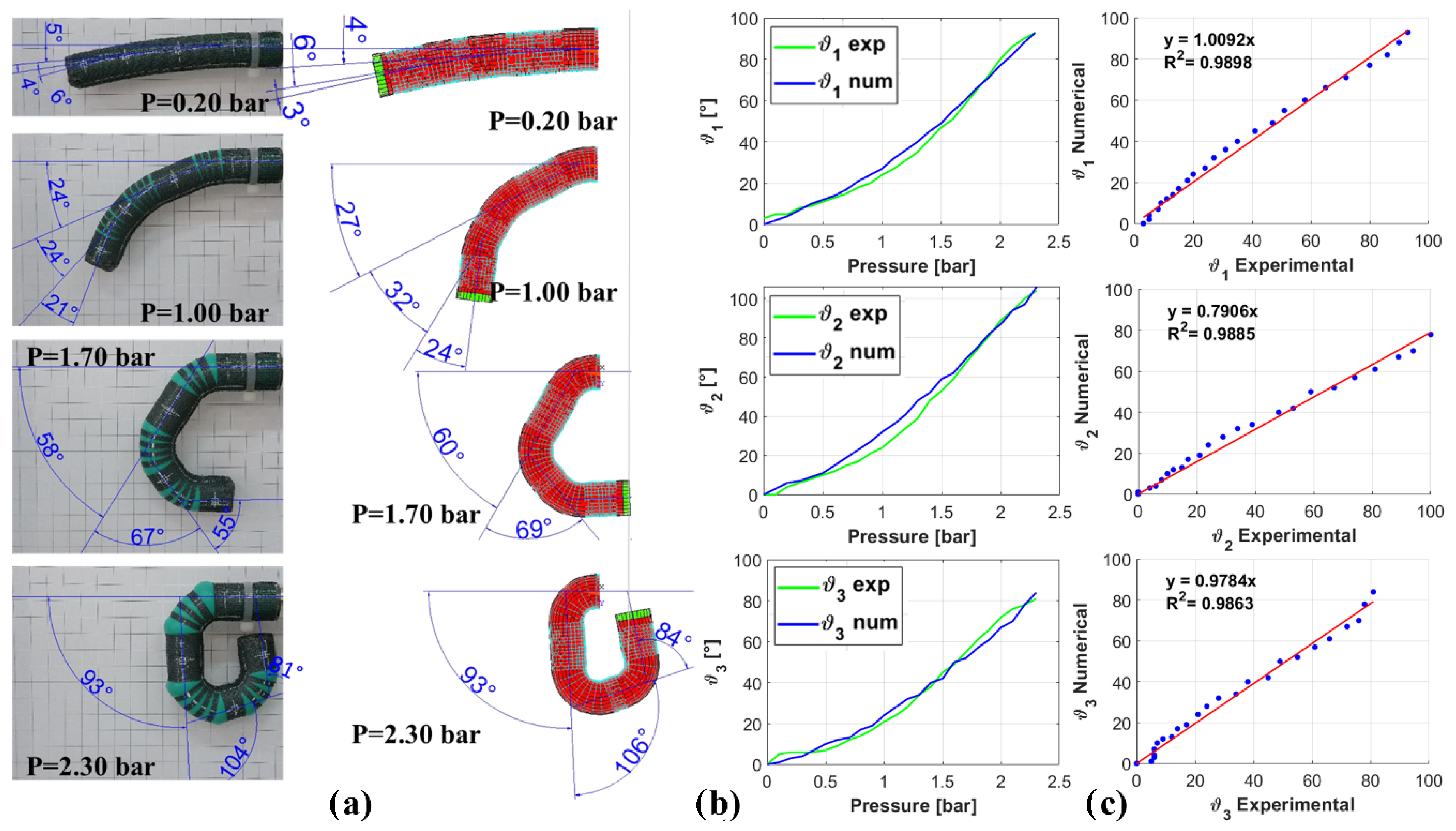
The simulations of the model were carried out at the same final pressure value. Pictures and screenshots were acquired for each 0.10 bar step for the experimental prototype and FEM model, respectively. A camera (13 Mpixel, resolution, 4128 × 3096 pixel) of a smartphone was used for the pictures: it was placed on the test bed at a distance from the prototype of about 2 m in order to limit the perspective effect. A comparison between the experimental and numerical angles was carried out in the Autodesk AutoCad 2019 Student Edition environment, by an image analysis of the pictures and screenshots, as shown in
Figure 3a.
The measured angles have been plotted on the same graphs for a qualitative comparison (
Figure 3b). Finally, to quantitatively validate the model, correlation and regression analyses between the experimental and numerical results were carried out, as reported in
Figure 3c. The results show a good fitting of the experimental and numerical curves. Greater absolute deviations resulted for the angle θ
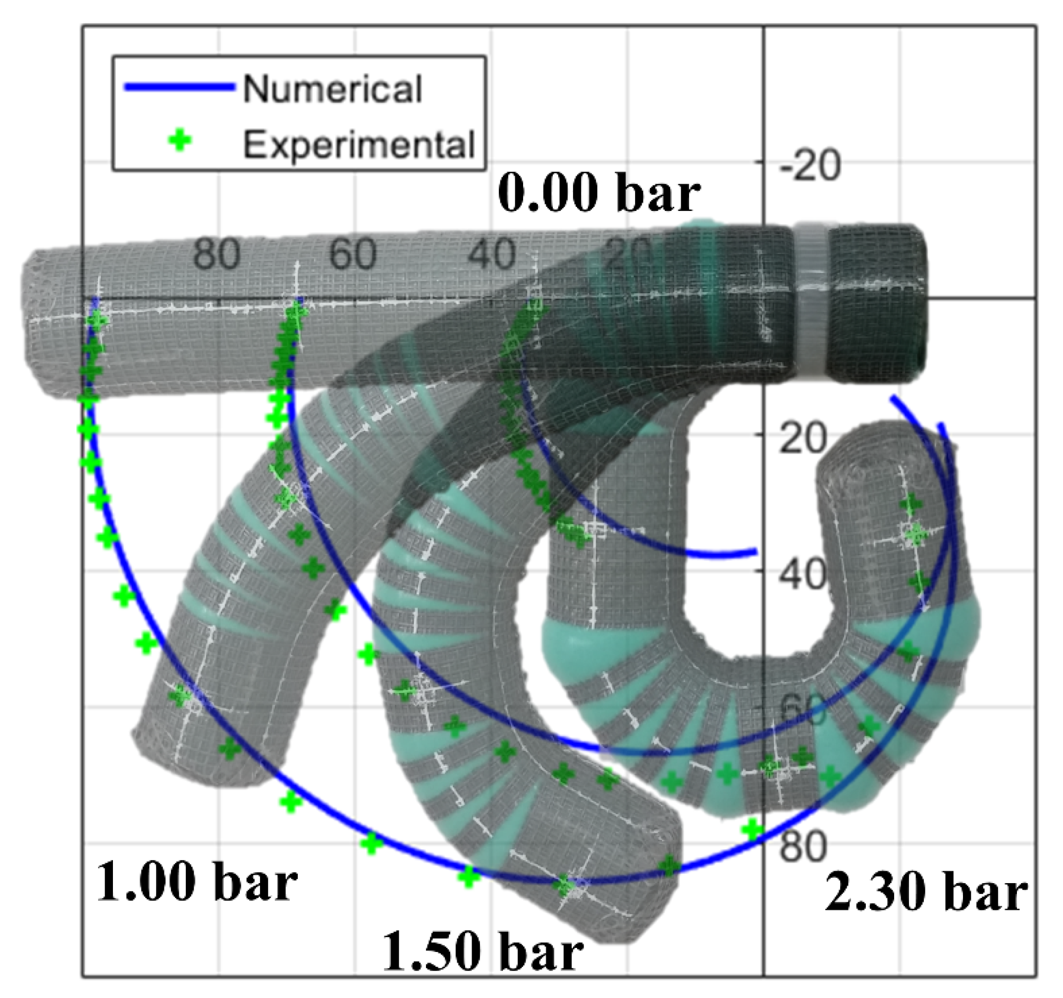
2. At the same pressure value, the model provides for greater angles until 1.50 bar; then, the experimental prototype exceeds. The latter result is well described by the comparison of the trajectories followed by the midpoints of each experimental and numerical phalanx, as shown in
Figure 4.
The deviations are probably due to the following issues: the fact that the model does not consider slipping between the gauze and the tube, the manufacturing process for the prototype, and uncertainties in the measurement of the angles through the image analysis.
The values of R2, close to 1, confirmed the validation of the model. Moreover, the experimental work tested the functionality of such a kind of actuator. For pressure values lower than 2.00 bar, the angles of the joint satisfied the relations (1)–(3); for values higher than 2.00 bar, the tube showed some bulges in correspondence of the joints.
3. The Predictive Formula
The formula was derived with the aim of it becoming a design tool in substitution for the FEM model. The formula, derived with the model, is intended as a mathematical expression for the prediction of the kinematic behavior of a soft actuator, according to several sets of functional and geometrical parameters. A qualitative prediction is expected due to the inability of the FEM model to consider fabrication errors and the real behavior of the adopted materials.
The derivation of the formula was based on the consideration that, for the
i-th joint, the bending angle (θ
i) can be expressed as:
where
α is the value of alfa_closed and
P is the internal pressure value. In the present study, the geometrical parameter
D was set equal to 20 mm, to mirror the shapes of objects whose dimensions are lower than 100 × 100 × 100 mm, at an operating pressure in the range 0.0–2.00 bar; the geometrical parameter
s was set equal to 2 mm, to reduce the bending resistance of the tube (i.e., lower values of pressure for bending), to reduce the overall mass of the actuator and to avoid the occurrence of the bulges on the joints.
Hence, the formula to be derived can be expressed as:
with the additional consideration that, as result of a preliminary study [
36], an increase in
P and
openFi provides for an increase in
θi, while an increase in
αi provides for a decrease in
θi.
To formulate (5), a simplified FEM model was implemented. It is made of one joint, between the Root and F1, both equal to 30 mm. To improve the resolution of α, the element size was set equal to 1 mm: the circumference of the tube was subdivided into 60 elements, each with an angular extension equal to 6°, for a resolution equal to 12°. The value of alfa_center was set equal to 270°. The pressure range was set equal to 0.0–2.00 bar. Several simulations were carried out, changing the values of some parameters, as described in the following. For each simulation, the values of θ were measured by the image analysis during the test on the prototype, as previously described.
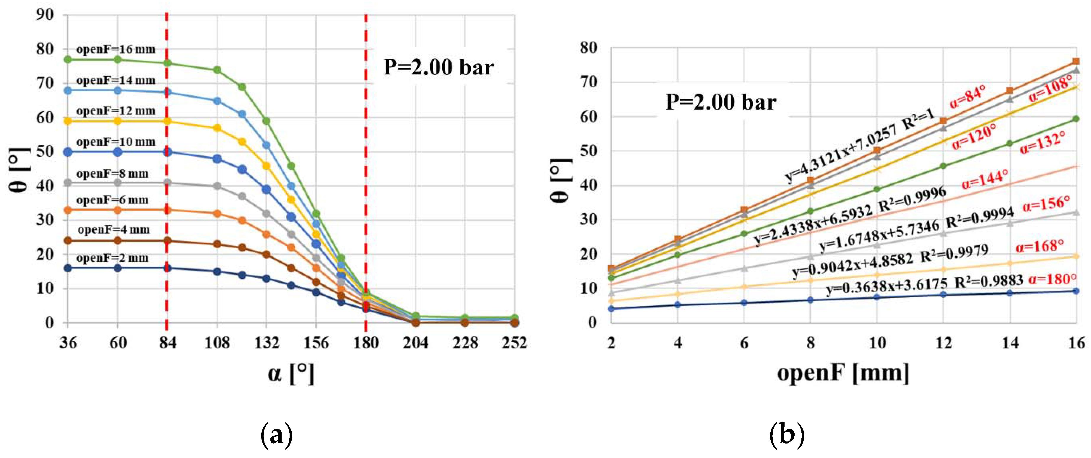
3.1. Significant Range of α and Preliminary Consideration about θ vs. OpenF
A preliminary set of simulations was carried out to find the range of values of
α that provided for a significant change in
θ and that reduced the overall number of the next sets of simulations. For different values of
openF, in the range 2–16 mm, and
α, in the range 36°–252°,
θ was measured where it reached the highest value, in correspondence of 2.00 bar. The results, shown in
Figure 5a, suggested considering the range 84° ≤
α ≤ 180°: lower values of
α provide for no significant changes in
θ; higher ones provide for values near to zero.
A secondary set of simulations was carried out to determine the behavior of
θ as a function of
openF. For different values of
openF, in the range 2–16 mm, and
α, in the significant range,
θ was measured in correspondence of 2.00 bar. As shown in
Figure 5b, a linear dependency on
openF, regardless of the value of
α, results from the equation of the linear regression lines, whose R
2 value is close to 1 (for sake of clarity, some equations have not been reported). As expected, the increase in
α provides for a decrease in
θ.
Such a result allows one to write the following expression, which must be verified over a wide range of pressure, to properly formulate (5):
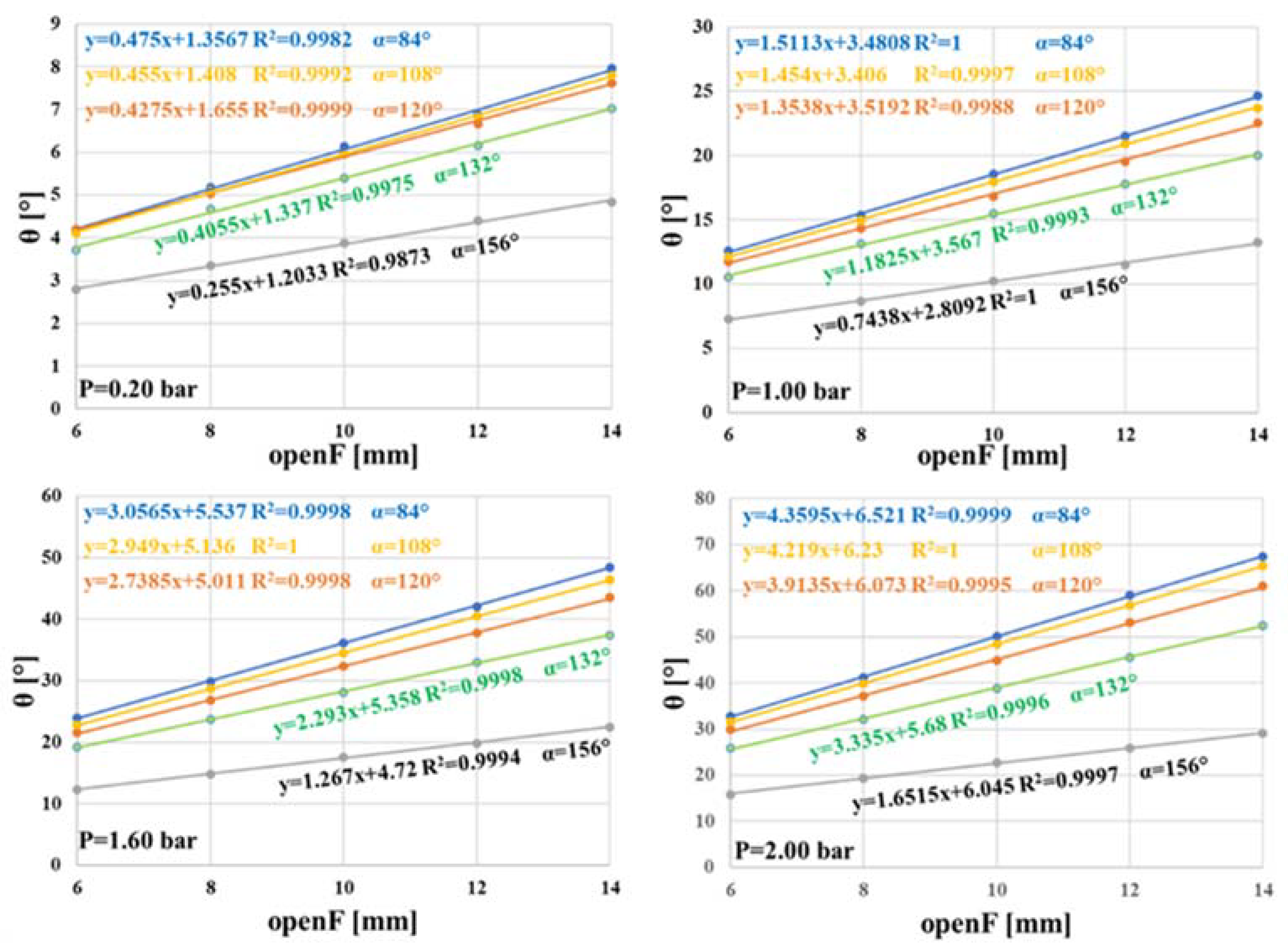
3.2. Achievement of the Predictive Formula
On the basis of (6), and to reduce the number of simulations, the procedure for deriving the formula was based on models built on five values of
openF (6, 8, 10, 12 and 14 mm) and
α (84°, 108°, 120°, 132° and 156°), considering all the possible combinations among them. Twenty-five simulations were carried out: by the image analysis,
θ values were measured in the range 0.0–2.00 bar, with a step of 0.20 bar. At each step, and for the same value of
α,
θ values were collected for the different values of
openF, as shown in
Figure 6, where the data of only four pressure values are reported. As expected, an increase in
P provides for an increase in
θ.
The linear behavior of
θ was confirmed for all pressure values, and (6) can be improved as:
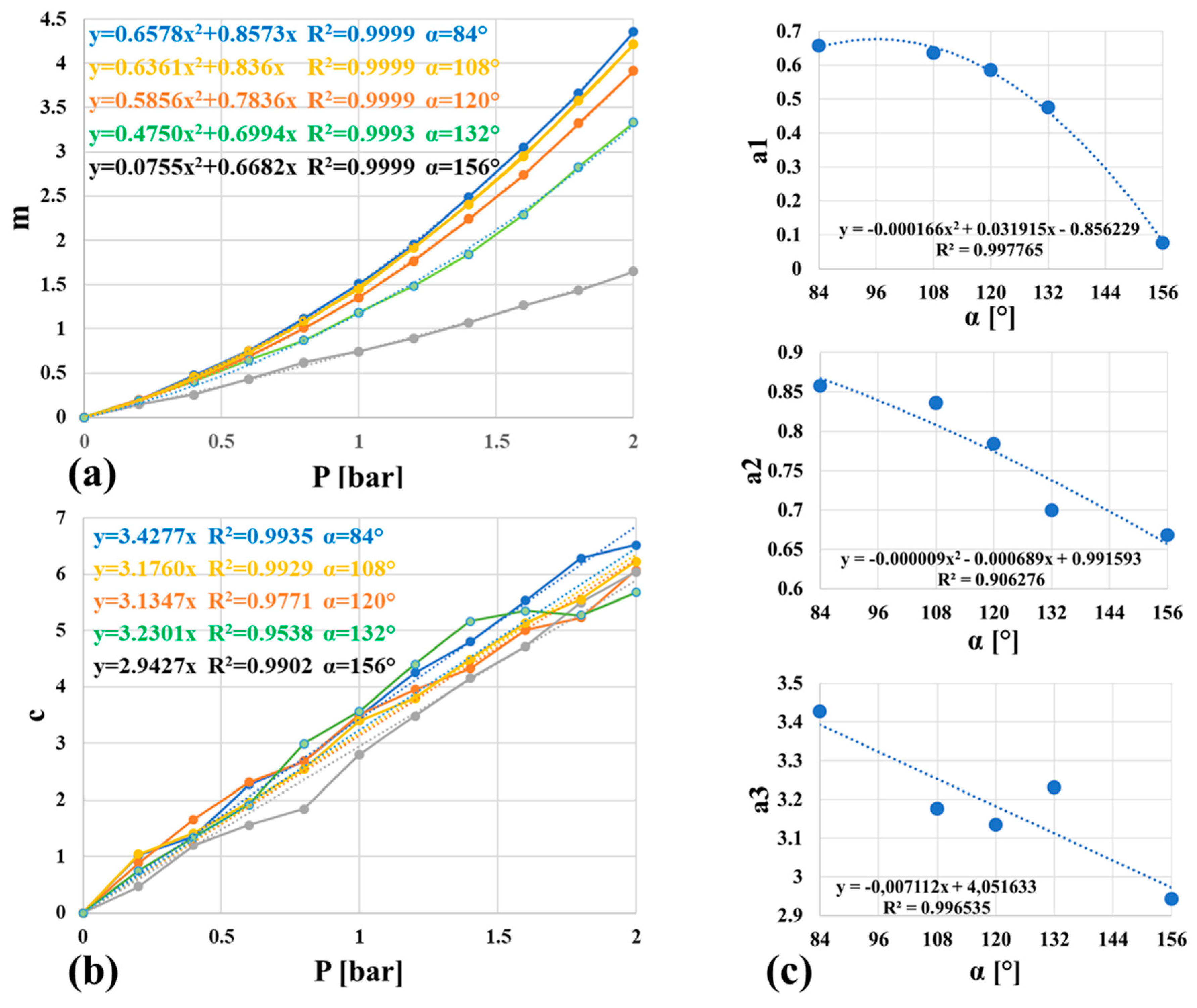
To determine the behavior of
m(αj, Pk) and
c(αj, Pk), the methodology proposed in [
37] was applied: for each
αj,
m(αj, Pk) and
c(αj, Pk), values were collected and plotted as a function of
P, as shown in
Figure 7. Then, the shapes and the equations of the regression lines were found. Due to the value of R
2, the behavior of
m(αj, Pk) can be well described by a parabolic curve; on the contrary, the behavior of
c(αj, Pk) can be described by a discrete approximation of a line. The expression (7) can be improved as:
where
ã1(αj) and
ã2(αj) represent the set of the coefficients of the equation of the parabolic curves of
Figure 7a and
ã3(αj) represents the set of the gradients of the lines of
Figure 7b.
Finally, the behaviors of the
ã1(αj),
ã2(αj) and
ã3(αj) coefficients have been plotted as a function of
α, as shown in
Figure 7c: two parabolic curves and one line better describe their behaviors, respectively. The coefficients of the equations of the regression curves were adopted to finalize the formula.
Hence, the derived formula is:
The values of the coefficients are reported in
Table 3.
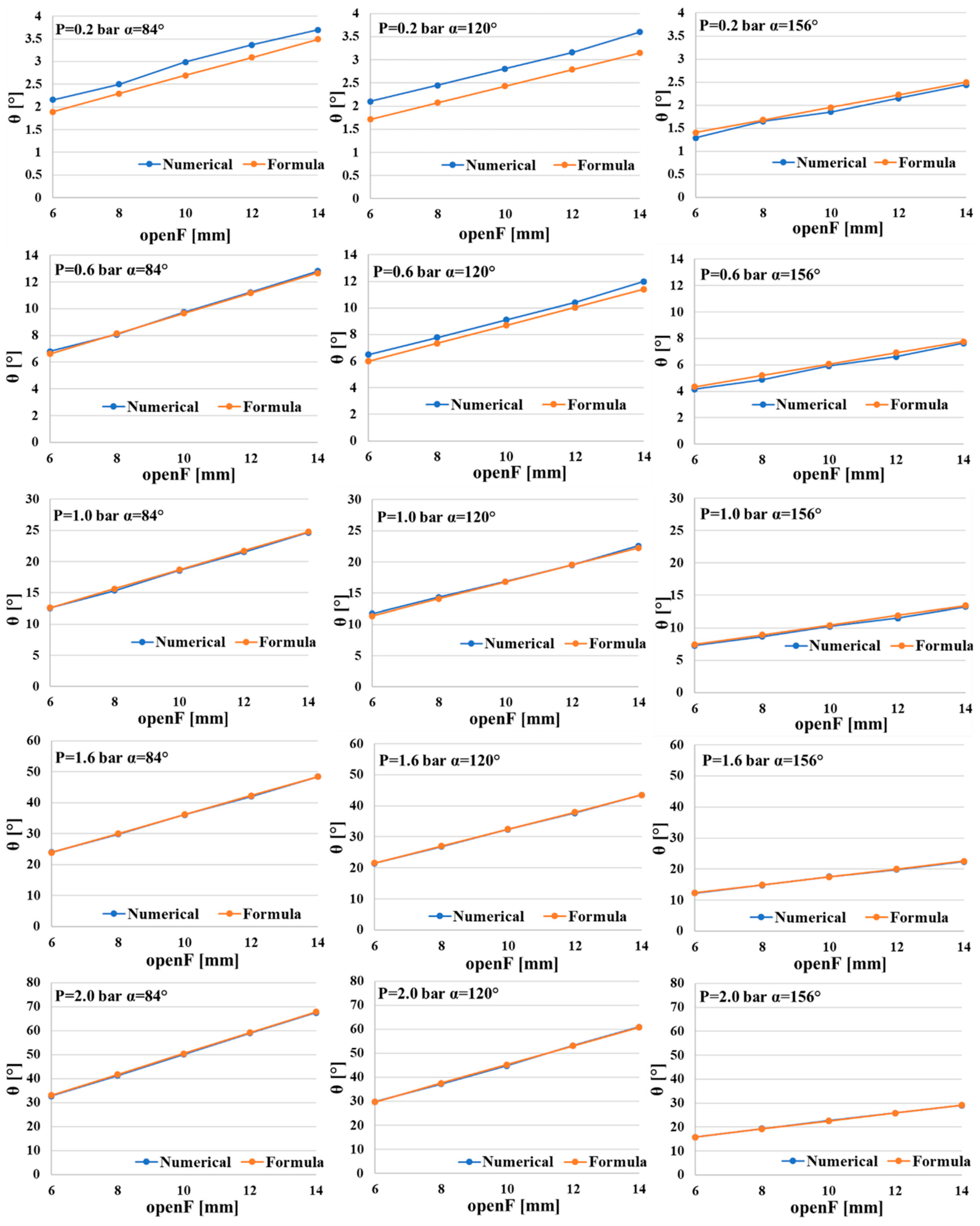
3.3. Validation of the Formula
θ values were computed using the formula and compared to the values obtained with the numerical model. Some results are reported in
Figure 8. With the exception of values of pressure equal to 0.20 bar, where the bending is close to null, and for
α equal to 120° until 0.60 bar, where low differences result, the behaviors of numerical
θ are the same as the formula ones. This result validates that the formula that can be adopted in substitution for the FEM model for the design of the proposed type of soft actuator. In particular, for a desired value of
θ, the couple of values of
openF and
α and the proper pressure values can be achieved, as described in the next section.
4. The Design Methodology: A Case Study
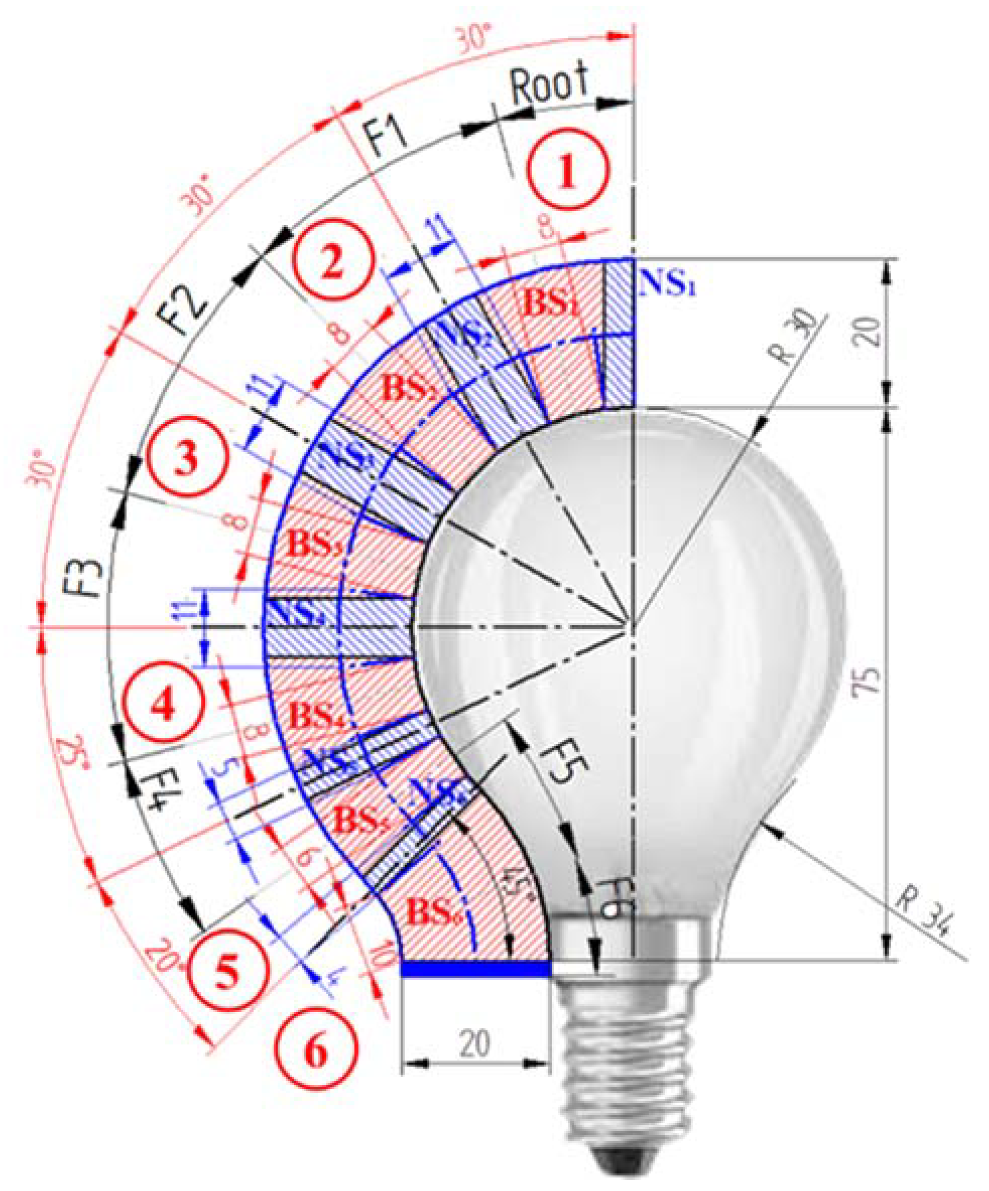
The presented soft actuator has the ability to kinematically mirror the shape of an object. The proposed design methodology was applied with the idea of grasping a light bulb: it is a lightweight and fragile object whose geometry shows opposite curvatures, and it is feasible for it to be grasped by a soft actuator. With reference to
Figure 9, the design methodology is articulated through the following steps:
The import of the geometry/picture of the object to be grasped in a CAD environment (see the picture of the light bulb).
The design of the useful profile of the object to be grasped (see the black inner profile on the left side of the light bulb).
The design of the external profile of the actuator as an external offset of the inner profile, according to the value of the diameter of the tube (see the blue profile with an offset of 20 mm).
The discretization of the wanted shape of the actuator in a series of joints (indicated by the numbers in the red circles). Each joint is made of a bending sector (see the dashed red areas, BSi) among two nondeformable sectors (see the dashed blue areas, NSi) that will be totally wrapped by the gauze.
Generally, it is better to increase the number of joints to better follow the desired profile. The centers of the bending sectors must coincide with the center of the curvature of the profile of the object. The length of each bending sector is arbitrary; nevertheless, the greater the length, the greater the effect of the polygonal chain, and a non-optimal fitting could occur.
Measurements of the following entities:
- -
θ of the i-th joint (see the red angular dimensions): it is the bending angle measured between two lines of discretization.
- -
openF of the i-th joint (see the red linear dimensions): it is measured as the linear dimension of the bending sector on the inner profile. After the discretization, the openF value must be approximated by excess to become the closest integer and multiple of two (due to the dimensions of the adopted gauze).
- -
The length of the i-th nondeformable sector between two adjacent joints: it is the linear dimension (see the blue linear dimensions) measured between the intersection points of the curved axis of the wanted shape with the perpendicular lines starting from the extremities of the nondeformable sector placed on the inner profile.
Achievement of the length of
Fi: as shown in
Figure 1b, it is the linear dimension computed as
Collecting the values of F, openF, alfa_center and θ for each joint.
The application of the formula to derive the values of αi and the maximum operating pressure value.
Formula (9) allows the construction of a numerical table. A section of it is reported in
Table 4. According to the following procedure, the pressure and
αi values are achieved by:
The
recognition of the maximum operating pressure value: entry into the table by the column of
openFi corresponding to the highest value of
θi resulting from Steps 1–7; from the row corresponding to the highest value of the pressure towards rows with lower values of it, for each row, move from the left to the right until the current value of
θi is equal to the wanted one or to a next higher available value of it; the row including the cell with such a value provides the maximum operating pressure value (to be read from the left column of
Table 4), while the column including it provides the
αi value (to be read from the lowest row of
Table 4). In the case reported here, the highest value of
θi is 45° and the corresponding value of
openFi is 10 mm. Then, in the column of
openFi = 10, the value of
θi nearest to the wanted one is 45.3°, in the black thick line cell. From this cell, moving leftward, the maximum operating pressure value is equal to 1.90 bar (in the green thick line cell); moving downward, the
αi value is equal to 132° (in the blue thick line cell).
The recognition of the values of the remaining parameters: in the row of the recognized maximum operating pressure value, for the i-th joint, seek the entry in the column with the wanted openFi and find the closest and highest value of the corresponding θi; then, moving downward, the value of αi is recognized as previously described.
The actuator proposed here is made of six joints, whose design parameters, determined by the abovementioned procedure, are reported in
Table 5:
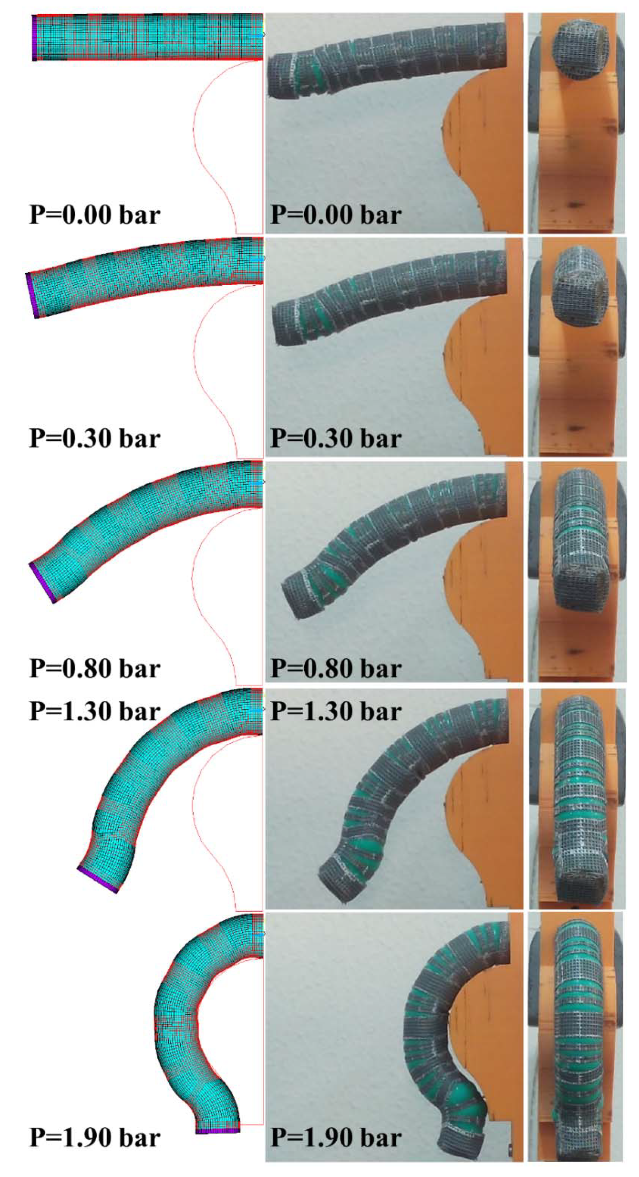
The validation of the design methodology was carried out by the experimental evaluation of the kinematic behaviour of the prototype of the actuator built on the basis of the values reported in
Table 5. A test bed, made of commercial aluminium profiles, and a simulator of the light bulb, made by rapid prototyping, were realized. A precision pressure regulator and a manometer completed the test bed. The maximum value of the pressure was set equal to 1.90 bar. At steps of 0.10 bar, a picture of the actuator was taken. The test was carried out like the test for the experimental validation of the numerical model.
Figure 10 shows the kinematic behaviour of the experimental prototype. As further validation, the numerical model of the actuator was implemented: the actuator moves toward the 2D shape of the light bulb.
The experimental prototype provides for a good mirroring of the shape of the object. Some bulges appear at the maximum value of θ. In correspondence of the opposite bending, some little deviations occur between the two shapes. Nevertheless, due to the variable stiffness of the actuator, the increase in the pressure from the maximum value provides the optimal fitting. On the contrary, the numerical model, i.e., the analytical formula, provides for an optimal mirroring. Such results are encouraging for future designs of the proposed actuators.
Experimental work was also performed to measure how fast the bending and recovery process of the actuator was. A pneumatic circuit, made of the previously cited components and of a monostable three-way manual command pneumatic valve, was mounted. The pressure value was fixed equal to 1.90 bar. The manual command of the valve, from the stable position, provided for the bending. A movie of the bending and recovery process was acquired by the same camera adopted in the experimental validation of the numerical model. By analyzing the movie, it was found that the bending process required 0.942 s and the recovery one, 0.234 s. This result gives an idea of the working frequency of the actuator: about 1 s is required from the positioning of the end effector on the lamp to a sure grasp of it. Moreover, the effect of the elastic energy stored by the silicone rubber tube is evident; this effect is much more evident when the actuator reaches the rest position, in correspondence of which a damped vibration can be observed.
5. Conclusions
In this paper, a bending pneumatic soft actuator, with the ability to kinematically mirror the shape of an object, has been presented. It is made of an externally reinforced hyper-elastic tube; the external reinforcement, made of a square mesh gauze, shows some cuts to guide the bending of the joints of the actuator and to avoid linear elongations. Such an underactuated actuator has a non-linear behaviour; for this reason, a numerical model was developed and experimentally validated in order to derive a predictive formula for the kinematic behaviour. This formula was validated. Its adoption allowed managing a design tool for actuators characterized by different functional and geometrical parameters, in substitution for the numerical model. Based on the formula, a design methodology was defined and experimentally validated. The most evident results of the presented study are the definition of a new type of actuator, the definition of the steps for its realization, the formula and the design methodology both being experimentally validated, and the feasibility of the actuator being adopted in an industrial application being demonstrated.
The last result is encouraging: experimental work demonstrated that the actuator really had the capability to kinematically mirror an object, and the time required for its bending and for recovering the rest position are compatible with typical pick-and-place operations in industrial applications: less than 1 s for the first and less than 0.3 s for the second. In the current work, the only case study for the grasping of a light bulb has been reported. Nevertheless, the design method can be adopted for several objects whose geometry may be axisymmetric or not: in the first case, three or more similar actuators could be assembled along a circumference to create a symmetrical end effector; in the second one, on the basis of the shape of the object to be grasped, different (for the final deformed shape) actuators could be positioned in a non-symmetric end effector, in order to kinematically mirror the most significant profiles of the object.
In both cases, the actuators provide for the grasping and releasing of the objects, in total safety and with a tight grasp; the robot moves the end effector at the desired speed and to the wanted position, with the typical positioning accuracy and repeatability of a collaborative robot (at least ±0.1 mm). Any misalignments are corrected by the compliance of the actuators. A typical scenario could be the following one: when an object, of a defined shape, reaches the work volume of the robot, the end effector is moved on the object and actuators are commanded to grasp it, from its sides; then, the robot moves the end effector to the unloading area, where the object is released and the actuators recover the rest position. To ensure the expected reliability, the end effector and robot must communicate by means of industrial sensors and devices: a control unit (a Programmable Logic Controller or an own command unit of the robot, for example) receives signals from the robot; acquires signals from sensors, as input entities; and sends signals to the robot and to the end effector, as output entities. Then, when the object is approached, the robot gives the command to a pneumatic electro-valve, installed on the end effector; then, actuators start to bend: the current bending or the contact force between the actuator and the object could be measured by flexible resistive and piezoresistive sensors, respectively; when the bending or the contact force values, or both, reach a threshold, the control unit commands the robot to move towards the unloading area; when this area is reached, the robot communicates its position to the control unit that provides for the command of the pneumatic electro-valve: the actuators recover the rest position.
Moreover, some improvements have been considered: a tubular flexible structure, equipped with cuts and realized in flexible plastic material by rapid prototyping, can replace the square gauze; sensor packages must be identified to be adopted for the measurement of the current bending of each joint and, above all, for the measurement of the contact forces between the actuator and the object to be grasped. A research activity for the design of a grasper equipped with such actuators is in progress. In particular, the grasper will be mounted as an end effector of a collaborative robot for carrying out the grasping tasks. The idea is to realize a grasper able to support several interchangeable types of actuators for objects with different shapes. Finally, a GUI interface has been conceived in order to realize an FEM model whose bending can occur in several planes of space such as, for example, for a helical actuator. A future development of the research will be to apply the proposed methodology for designing helical actuators, as proposed by some researchers [
40,
41], to be adopted for grasping tubular and axisymmetric objects.


