1. Introduction
The development of the electronic equipment makes it necessary to constantly increase the intensity of heat transfer. One of the methods often employed to achieve that goal is the impinging jet. Recently, a regular continuous jet has been increasingly replaced in various applications by a synthetic jet (SJ) which provides better cooling and heat transport properties [
1,
2]. The SJs are particularly useful in the LED cooling systems such as SynJet
® [
3] or the configuration investigated in [
4]. SJ is also used in flow control [
5,
6], mixing [
7,
8] and other fields.
The SJ is generated by the periodical suction and expulsion of fluid to the actuator cavity. In order to achieve this, at least one of the cavity walls must be replaced by a movable or deformable element (e.g., loudspeaker diaphragm, piezoelectric transducer or piston). The periodic change of the cavity volume causes the flow of the fluid through the actuator’s orifice.
In heat transfer applications, the alternative to using a SJ in an impinging arrangement is to place the fins of the heat sink directly in the cavity chamber [
9]. In such cases, the cold air is sucked from the environment into the cavity and after receiving heat from the fins it flows back through the orifice as SJ. Due to the size considerations, a loudspeaker diaphragm is a more suitable option for a moving wall in this type of actuator, however an application of a large number of cooperating piezoelectric transducers may also be feasible. The evident downside of the synthetic jet actuator (SJA) is the fact that it can generate excessive noise.
Kanase et al. [
10] measured the sound pressure levels (SPLs) of the actuators with four
t/
d (orifice thickness to diameter) ratios inside and outside the acoustic chamber. They proved that the SPL generated by SJA is inversely proportional to the
t/
d ratio and mainly depends on the orifice thickness—spreading of sound wave increases with the orifice thickness.
The heat transfer characteristic and acoustic aspect of SJ were investigated in [
11,
12]. Bhapkar et al. [
12] investigated SJAs with three types of orifice shapes, two orifice thicknesses and different aspect ratios (a total of 12 cases). They measured the SPL and heat transfer coefficient. The SPL was related to the orifice shape and increased smoothly with the orifice aspect ratio. The minimum SPL was generated at the SJA characteristic frequency and turned out to be directly proportional to the orifice thickness. The SPL increase with the orifice thickness was attributed to the higher flow resistance in the orifice. Notably, it is a direct contradiction of the trend observed in [
10]. Bhapkar et al. [
12] indicated a significant correlation between the acoustic and heat transfer characteristics of SJ but they did not explain how it manifests itself.
Arik [
13] investigated the piezoelectric SJA for heat transfer applications. The heat transfer and acoustic experiments were carried out with two different measuring setups. The SPL measurements were conducted in an anechoic chamber for two different driving voltages (50 and 90 VRMS) and three frequencies. The initially measured SPL was in a range of 60–70 dB which is a level that excludes SJA from many applications. In order to reduce the noise level, the SJA was placed in a small (3 inch on each side) cube made of Plexiglas. A 10-mm orifice with a tightly attached muffler was located at one of the walls. Three different mufflers were used. The modifications allowed a reduction of the SPL even below 30 dB that is a typical background noise level of a room environment. The flow and acoustic properties of the SJ were not correlated and the aim of the investigation was to reduce the SPL without changing the heat transfer parameters.
The modification of the SJA power [
14], orifice thickness [
15], orifice shape [
16,
17] or the SJ generation method [
18] are the other ways to the SPL reduction. These methods had been described before for a classic SJA with an empty cavity. In this paper, the SJA with the fins inside the cavity is proposed. It would be reasonable to assume that aforementioned factors affect the SPL also in the SJA arrangement investigated in the present work, however it should be the subject of further studies. It should be assumed that SPL depends also on the fins shape and this hypothesis is tested in the present work. The parameter connecting the SPL and the flow conditions (e.g., SJ velocity) should be established in order to determine the optimal (among the available solutions) configuration of the SJA (this is the main subject of this paper). The optimal actuator in the aforementioned context should generate the lowest possible SPL with the highest flow parameters.
2. Materials and Methods
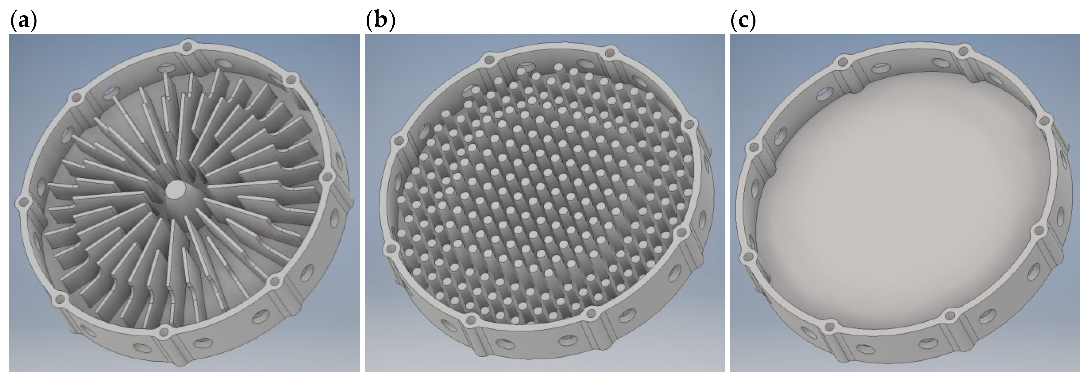
Three types of actuator’s enclosure design tested in present work are depicted in
Figure 1. Each type of the enclosure was based on a cylinder with an outer diameter of 172 mm and an inner diameter of 164 mm. The height of the enclosure was 30 mm and the base thickness was 4 mm. The total of 16 orifices with a diameter of 10 mm were located in the middle of the height of an enclosure wall. The first enclosure (case 1) featured 32 two-stage fins (16 with a length of 42 mm and another 16 with a length of 57 mm, arranged alternately) of 2 mm thickness (
Figure 1a). Second enclosure (case 2) had vertical pin fins with circular cross-section of 5 mm diameter arranged on a rectangular grid of 9 × 9 mm spacing (
Figure 1b). Third enclosure (case 3) had no fins (
Figure 1c). The enclosures were manufactured of thermoplastic polymer with fused filament fabrication (FFF) technique. Initially, a single enclosure of the geometry corresponding to case 1 from
Figure 1a had been CNC milled out of aluminum and studied in terms of the SPL and flow parameters with the methods described in the present section. Since the results did not deviate from the data obtained with the polymer enclosure of the same geometry (within the range of the measurement uncertainty), it was decided that within the scope of the present investigation, the polymer enclosures may be used in order to reduce the cost of the research.
Two different models of loudspeakers were used to set the fluid in motion—a woofer and a mid-range driver. Their parameters are presented in
Table 1. For similar loudspeaker diaphragm diameter, the SPL bandwidth starts to decrease below about 150Hz, thus utilizing the loudspeaker with a lower resonant frequency “a” should result in a lower SPL than for the loudspeaker “b” with a higher resonant frequency.
For the purpose of the present paper, the SJA configurations are referred to as cases 1a, 2a, 3a, 1b, 2b and 3b. The designation includes the type of the enclosure and the model of the loudspeaker used for the given actuator, e.g., case 1b means that the SJA uses the first enclosure (case 1,
Figure 1a) and the loudspeaker “b” (STX M.18.200.8.MCX,
Table 1).
The SJA was supplied with a sinusoidal waveform from a Rigol DG4162 generator subsequently amplified by the AUNA CD-708 amplifier. Electrical parameters of the loudspeaker were measured with Keithley 2701 multimeter (6.5 digit, 22-Bit) with 7706 multiplexer card. The current was determined indirectly by measuring the voltage drop across the reference resistor (1 Ω, 0.01%). The apparent power measurement was performed with an uncertainty ± 0.25% of measured value.
The velocity of SJ was measured with a constant temperature anemometer (CTA) probe with temperature compensation connected to the ATU 08 bridge that features separate channels dedicated to the CTA measurements as well as the channels for the measurement of the temperature fluctuations with cold-wire method. The single probe was equipped with two wires—one wire measured the velocity while the other wire was used for the temperature measurement. The entire CTA anemometer setup (including particularly the bridge and the probe) was calibrated in the range of 0.3–49 m/s. The uncertainty of the velocity measurement was ±0.1 m/s in the range up to 2.6 m/s and ±2% of the measured value in the range above 2.6 m/s. The uncertainty of the temperature measurement was ±0.5 °C. The National Instruments NI-USB-6211 (16-Bit, 250 kS/s) card was used for the acquisition of the CTA bridge output signal. The sampling frequency was set automatically depending on the synthetic jet actuator working frequency. A constant number of 400 samples per one cycle was set. For each single measurement, a dataset of 100 cycles was recorded. For example, measurements of the synthetic jet actuator working at 200 Hz was performed at 80 kS/s frequency. The velocity measurements for one geometrical case was performed at a single orifice assuming similar velocity profiles at all orifices with the same diameter. This assumption had been validated in the auxiliary experiment from which it follows that the velocity profiles are similar.
A 3-axis manipulator with ±0.02-mm positioning accuracy was used for traversing the CTA probe. The measurement of the velocity profile was performed with the spatial step of 0.5 mm at the relative distance from the nozzle outlet of x/d = 0.1, where x is distance from the nozzle and d is nozzle diameter.
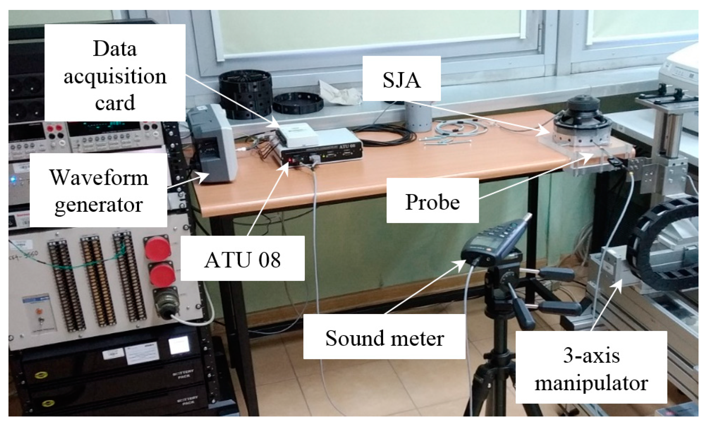
The sound pressure level (SPL) was measured using a Testo 816-1 sound level meter that complies with the requirements of the IEC 61672-1 Class 2 standard. The meter was equipped with a ½-inch microphone and its measuring range was 35–130 dB (C) in a frequency range of 20–8000 Hz. The measurement accuracy of the Testo 816-1 meter is ±1.4 dB. The sound meter was located 1 m from the test stand (
Figure 2). The measurements were performed according to ISO 3746:2010 that allows the experimental evaluation of the sound pressure level without an anechoic chamber. The measurements were performed automatically, without personnel in the laboratory room during measurement. The background SPL of the environment was confirmed to be at least 10 dB lower than the SPL generated by the SJA. The frequency weighting of the type C was applied for the SPL measurements. The National Instruments NI-USB-6211 card was used to record the output signal of the sound level meter.
The atmospheric pressure was measured using Honeywell HPB200W2DA-B barometer with the accuracy of ±40 Pa.
3. Data reduction
The most important parameter of a synthetic jet is velocity [
19]. In the present study, two different velocity formulations are used. The first is the centerline momentum velocity at the orifice axis:
and the second is the characteristic velocity:
where
T is the operation period of the loudspeaker membrane (s),
uc is instantaneous velocity at the orifice axis (m/s),
τ is the time (s),
A is the cross-sectional area of a single orifice (m
2),
u is the instantaneous velocity (m/s).
The resonant frequency of SJ was determined from the impedance vs. frequency curve with the electrical impedance defined as:
The energetic efficiency of the SJA was calculated with the formula [
20]:
where
ρ is the density of air (kg/m
3) calculated from the ideal gas law with the measured value of atmospheric pressure and temperature,
n is the number of orifices (
n = 16). The apparent power
P in Equation (4) was calculated as:
where
Erms is effective voltage [V],
Irms is effective current [A].
Generally, in Equation (5) the value of real power should be used. However, Gil and Smyk [
21] showed that the phase shift between current and voltage tends to zero for the resonant frequency. On the other hand, Broučková and Trávníček [
22] took the phase shift as negligible. In this paper, the efficiency was calculated only for the resonant frequency.
4. Results
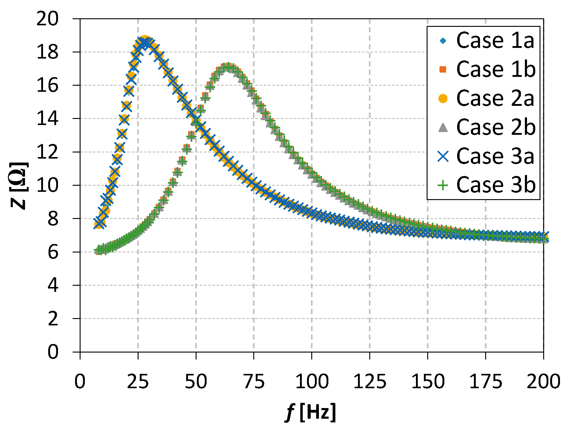
The first stage of the investigation was to find the characteristic frequency of SJA. For this purpose the impedance is plotted as a function of the operation frequency (
Figure 3). The characteristic frequency turned out to be dependent only on the model of the loudspeaker used and not on the type of the actuator’s enclosure. In cases 1a, 2a and 3a the characteristic frequency was found at
f = 28 Hz and in cases 1b, 2b, 3b at
f = 64 Hz. All the measurements aimed at finding the value of the resonant frequency were conducted at constant apparent power of
P = 4 W.
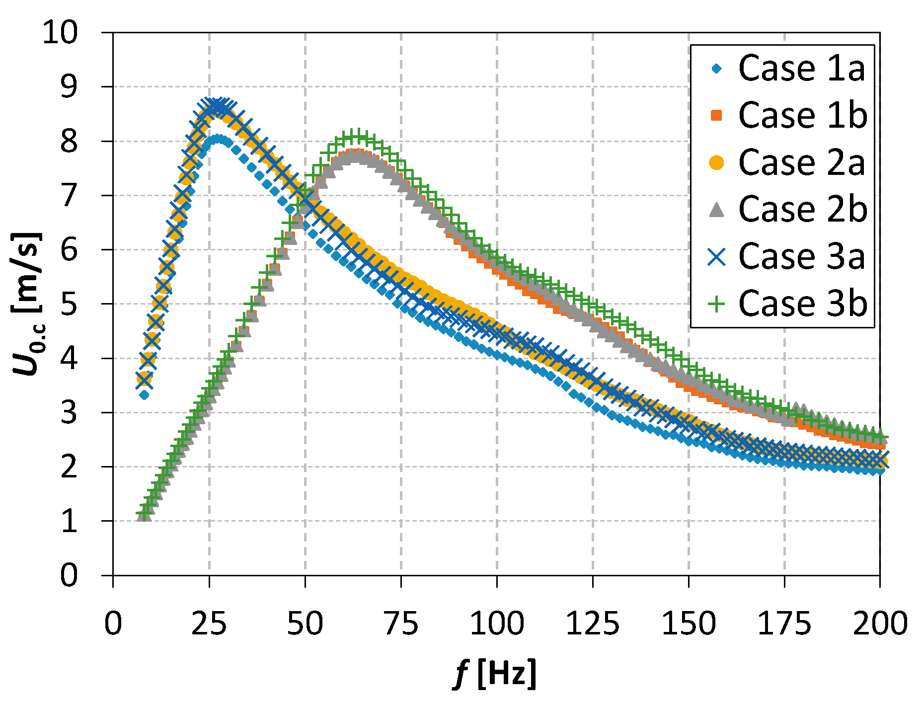
In
Figure 4, the centerline momentum velocity as a function of frequency is presented. The results are similar to those obtained with impedance measurements and particularly the values of the characteristic frequencies are the same. The highest velocity values were measured in the case 3:
U0.c = 8.64 m/s at
f = 28 Hz for the loudspeaker “a” and
U0.c = 8.1 m/s at
f = 64 Hz for the loudspeaker “b”. The lowest velocity was recorded for the enclosure 1. It may be inferred that fins obstruct the air flow in the actuator cavity by throttling it. This effect is more pronounced in the case of classic (rectangular) fins and less evident in the case of pin fins.
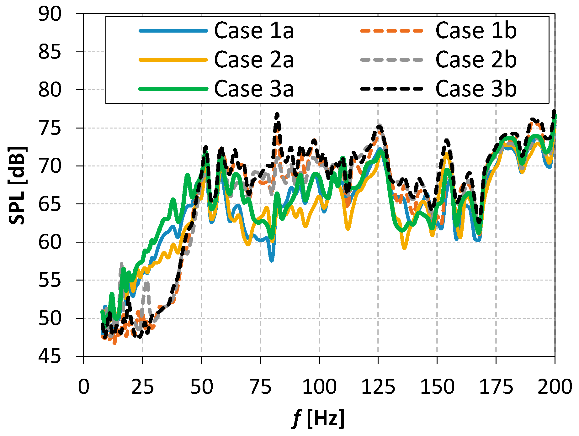
In
Figure 5, the values of the SPL generated by SJAs are presented. For the frequencies below 50 Hz (i.e., the point where the characteristics presented in
Figure 3 and
Figure 4 intersect) the SPL was lower for the loudspeaker “b”. Near the frequency
f = 28 Hz the SPL generated by the loudspeaker “a” is much higher than the SPL of the loudspeaker “b” but for the frequency range 64 Hz ≤
f ≤ 128 Hz the trend is opposite. For the frequencies
f > 128 Hz the SPL value is similar for both loudspeakers.
The type of the actuator’s enclosure design has also some impact on the SPL. At the characteristic frequency, the lowest values of SPL were obtained for the cases 2a (f = 28 Hz) and 2b (f = 64 Hz). The highest SPL values were obtained for the cases 3a and 3b in the whole frequency range.
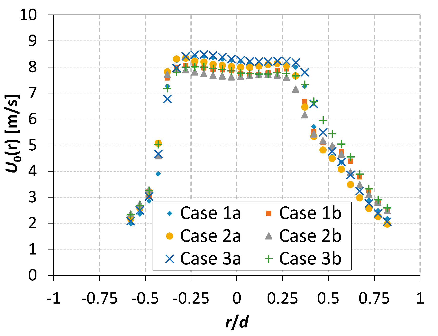
In
Figure 6, the momentum velocity profiles are presented. The measurements were taken along the vertical axis of the orifice (according to the setting of the SJA presented in
Figure 2). These profiles were used to calculate the characteristic velocity (Equation (2)) and the efficiency (Equation (5)). It may be observed that the velocity profiles are slightly asymmetrical. This asymmetry may result from the geometry of the presented synthetic jet actuator cavity, for example, the presence of the bottom of the cavity and/or fins. In the case of investigated actuators, the ratio of the orifice thickness to the diameter was
t/
d = 0.4.
5. Discussion
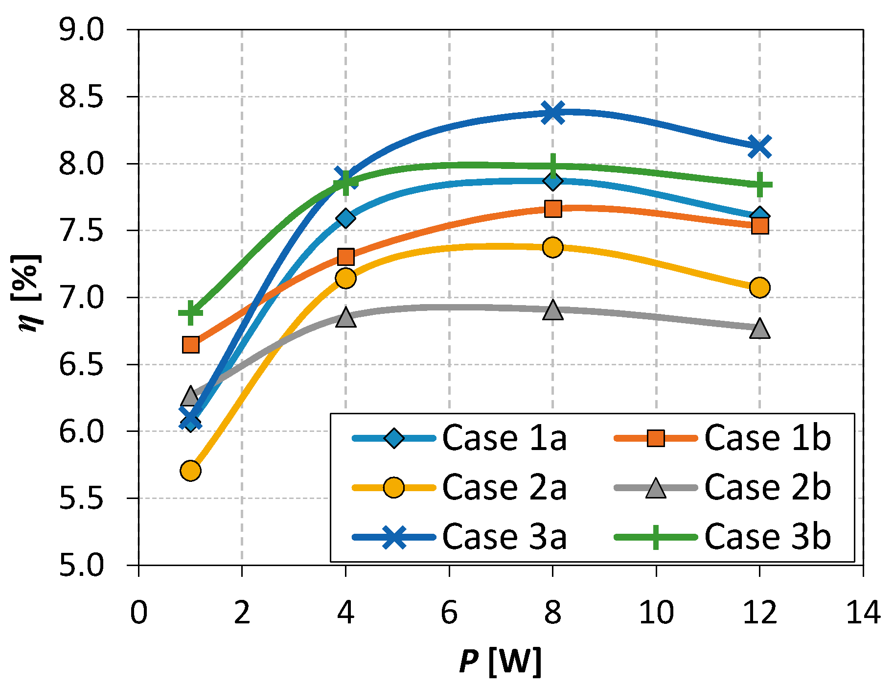
In
Figure 7, the SJA energetic efficiency is presented as a function of power. The measurements were carried out for the resonant frequency of the SJA. The highest values of the efficiency were obtained for the enclosures without fins which corresponds to cases 3a and 3b. For a given enclosure type, higher efficiencies were always observed in the case of a loudspeaker with lower resonant frequency (type “a”). The SJA efficiency reflects the throttling effect of the fins inside the actuator’s enclosure. The greatest flow attenuation in terms of
U0 occurred for the enclosure with pin fins arranged on the rectangular grid—for the cases 2a and 2b the efficiency was the lowest. Taking the points at
P = 8 W as an example, it may be observed that for both loudspeakers the efficiency obtained with regular fins is approximately 11% higher than efficiency obtained with pin fins. The efficiency of the empty enclosure is yet another 10% higher. It indicates that the presence and the shape of the fins in the actuator’s enclosure does not affect the operating parameters of the membrane (or such influence is negligible) but only the flow conditions in the actuator’s enclosure. This is confirmed by the fact that characteristic frequency of SJ is constant for all types of the actuator’s enclosure and depends only on the type of the loudspeaker used.
The loudspeaker “a” was previously used in the SJA investigated in [
20]. The highest efficiency of SJA equipped with this speaker obtained in [
20] was 4.76% while in present paper it reaches 8.38%. However, it should be noted that in [
20] the loudspeaker was supplied with lower power and a single-orifice actuator was investigated. The multiple-orifices SJAs tend to achieve greater efficiency than single-orifice ones [
21]. It is particularly evident when the SJ is used in the heat exchange applications [
23,
24].
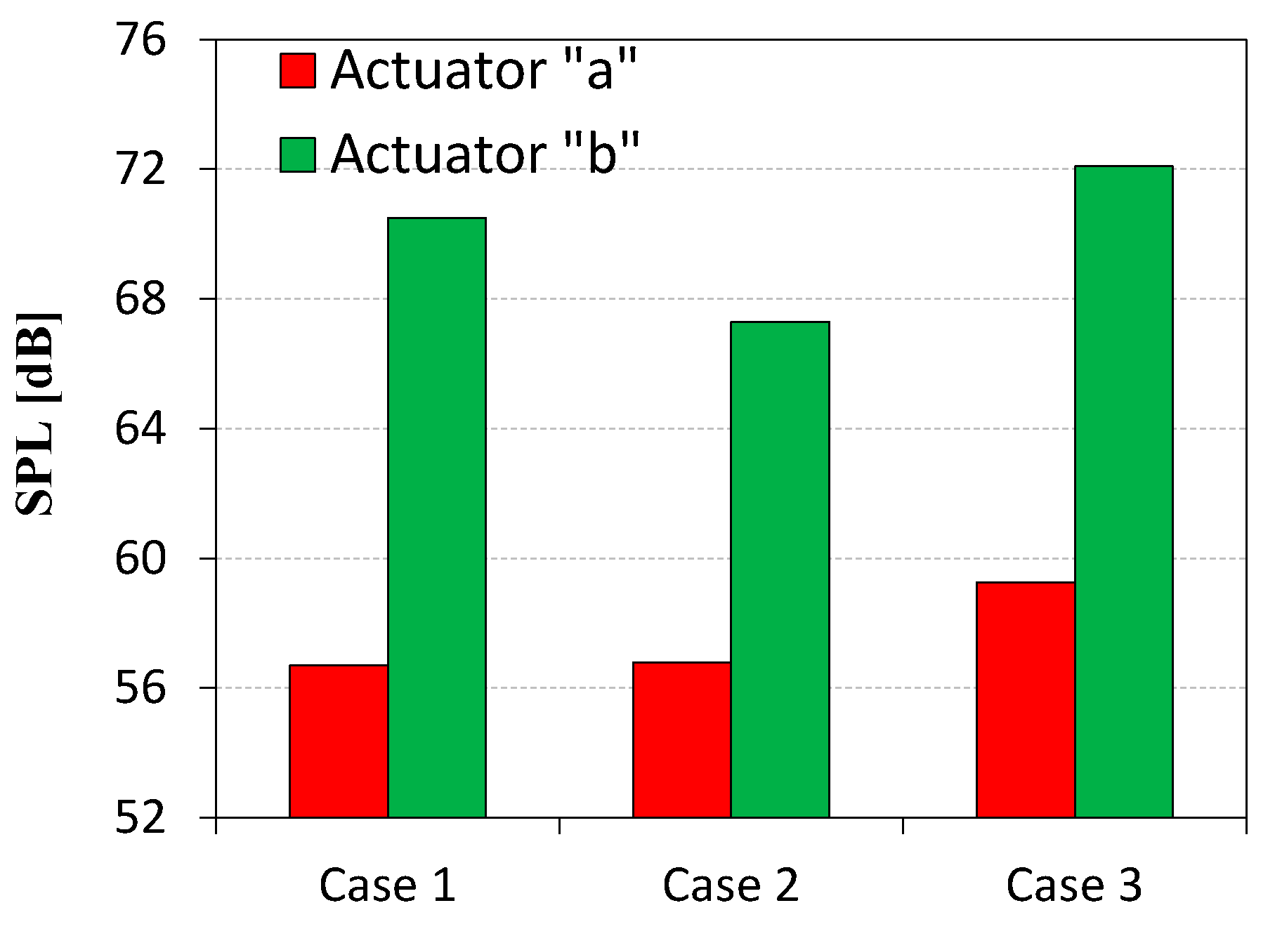
In
Figure 8, the SPL for the characteristic frequency and
P = 4 W is presented. The SPL generated by loudspeaker “b” was approximately 10–14 dB higher than the SPL of the loudspeaker “a”. The vertical pin fins (enclosure 2) reduced the SPL by nearly 2.5 dB (relative to the enclosure without fins) for the loudspeaker “a” and by 5 dB for the loudspeaker “b” with only slight drop in the efficiency value. In case 1a, the SPL reduction was similar but in the case 1b it was only 2 dB.
It must be noted that the SPL around 50 dB is acceptable in industrial conditions but not in offices where the equivalent sound level should not be higher than 55 dB [
25].
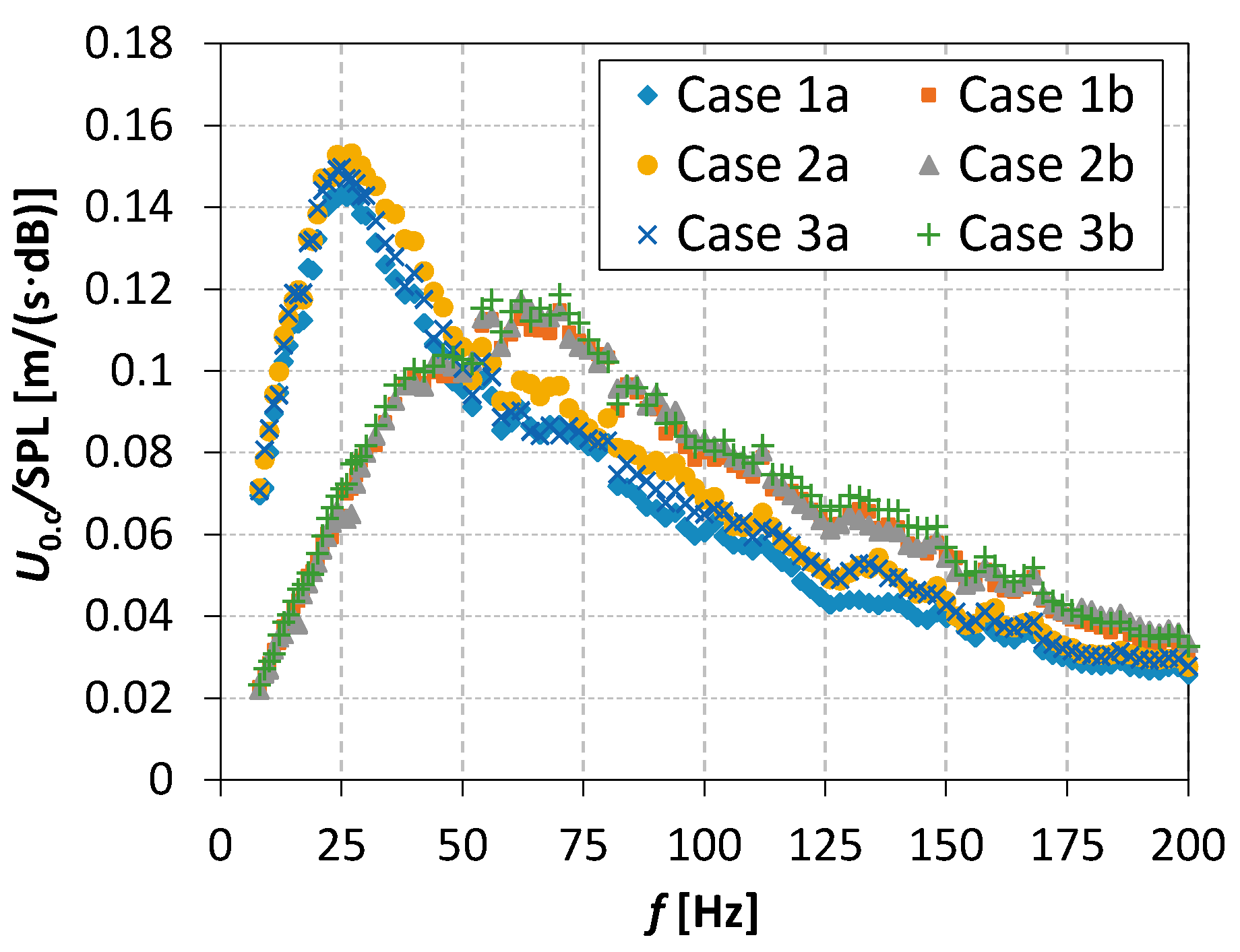
The main scope of the research presented in this paper is the choice of the optimal combination of the loudspeaker and the enclosure design type. For this purpose the ratio of the root-mean-square velocity at the orifice axis to the SPL is plotted as a function of frequency in
Figure 9. The ratio of the root-mean-square velocity at the orifice axis to the sound pressure level (
U0.c/SPL) ratio was higher for the loudspeaker “a” and did not vary significantly between different enclosure types (with maximum deviation of 0.01 (m/(s·dB))). The type of the loudspeaker used to set the fluid in motion turned out to be more important for the choice of the optimal variant than the fins’ arrangement in the cavity of the actuator. The highest
U0.c/SPL ratio was obtained for the case 2a, and this case was chosen as the optimal configuration.
Based on the results presented in this paper, it should be noted that for the design process of an SJA for the lowest possible SPL and the best flow parameters, the most important element of the actuator is the loudspeaker (or other device that sets the fluid in motion such as a piezoelectric transducer or piston). The fins shape and type have been proved to have a minor impact on the efficiency of SJA and the SJ velocity. It may be, however, anticipated that the fins’ arrangement will play a key role in the heat exchange in the actuator’s cavity and therefore the fins should be designed mainly with the heat transfer concerns in mind.
6. Conclusions
The main scope of the paper was to find the optimal SJA configuration in terms of the generated SPL and flow parameters. For this purpose, six different cases with three types of the enclosure design and two different loudspeakers were tested. For each case, the characteristic frequency was found and the SPL was measured at the distance of 1 m from the actuator. Additionally, the velocity profiles in the vicinity of the orifice outlet and the momentum velocity at the orifice axis were investigated.
The ratio of the root-mean-square velocity at the orifice axis to the SPL was used to find the optimal case. The highest U0.c/SPL ratio was obtained in case 2a that featured the pin fins inside the actuator’s enclosure and the woofer-type loudspeaker. An important observation is the negligible impact of the fins’ arrangement on the U0.c/SPL ratio. It suggests that in this regard, the type of the device used to set the fluid in motion (loudspeaker, piezoelectric transducer) is more important than the arrangement of fins in the cavity. Although the fins have an impact on the efficiency of the SJA, it is rather weak and the presence of the fins did not prevent the SJA from reaching quite a high efficiency of 6.9–8.38% for P = 8W. These observations allow us to conclude that the fins’ arrangement should be optimized in the terms of the heat transfer rather than in terms of the SPL or flow parameters.
Author Contributions
Conceptualization, methodology, project administration and funding acquisition, P.G.; software, formal analysis and validation, Ł.P.; investigation, P.G. and R.G.; visualization, data curation, and writing—original draft preparation E.S.; writing—review and editing and supervision, R.G.; All authors have read and agreed to the published version of the manuscript.
Funding
This work was supported by the National Center for Research and Development, Poland. Grant No.: LIDER/6/0024/L-10/18/NCBR/2019.
Conflicts of Interest
The authors declare no conflict of interest.
References
- Krishan, G.; Aw, K.C.; Sharma, R.N. Synthetic jet impingement heat transfer enhancement—A review. Appl. Eng. 2019, 149, 1305–1323. [Google Scholar] [CrossRef]
- Gil, P.; Wilk, J. Heat transfer coefficients during the impingement cooling with the use of synthetic jet. Int. J. Sci. 2020, 147, 106132. [Google Scholar] [CrossRef]
- Schwickert, M.M. SynJet® Thermal Management Technology Increases LED Lighting System Reliability. IEEE Trans. Reliab. 2010, 59, 449–482. [Google Scholar]
- Song, B.M.; Han, B.; Bar-Cohen, A.; Arik, M.; Sharma, R.; Weaver, S. Life prediction of LED-based recess downlight cooled by synthetic jet. Microelectron. Reliab. 2012, 52, 937–948. [Google Scholar] [CrossRef]
- Rosenblum, J.P.; Vrchota, P.; Prachar, A.; Peng, S.H.; Wallin, E.; Eliasson, P.; Iannelli, P.; Ciobaca, V.; Wild, J.; Hantarais-Gervois, J.L.; et al. Active flow separation control at the outer wing. CEAS Aeronaut. J. 2019, 1–14. [Google Scholar] [CrossRef]
- Asgari, E.; Tadjfar, M. Active Control of Flow over a Rounded Ramp by Means of Single and Double Adjacent Rectangular Synthetic Jet Actuators. Comput. Fluids 2019, 190, 98–113. [Google Scholar] [CrossRef]
- Le, L.V.; Bui, T.T.; Nguyen, C.N.; Nguyen, A.N.; Dinh, T.X.; Dang, L.B.; Tran, C.D.; Chu, T.D.; Dau, V.T. Simulation and Experimental Study of a Synthetic Jet Valveless Pump. IEEE/ASME Trans. Mechatron. 2019, 25, 1162–1170. [Google Scholar] [CrossRef]
- Wang, P.; Shen, C. Characteristics of mixing enhancement achieved using a pulsed plasma synthetic jet in a supersonic flow. J. Zhejiang Univ. Sci. A 2019, 20, 701–713. [Google Scholar] [CrossRef]
- Gil, P. Performance of special type heat sink with an integrated synthetic jet actuator. E3s Web Conf. 2019, 100, 17. [Google Scholar] [CrossRef]
- Kanase, M.M.; Mangate, L.D.; Chaudhari, M.B. Acoustic aspects of synthetic jet generated by acoustic actuator. J. Low Freq. Noise Vib. Act. Control 2018, 37, 31–47. [Google Scholar] [CrossRef]
- Bhapkar, U.S.; Srivastava, A.; Agrawal, A. Acoustic and heat transfer aspects of an inclined impinging synthetic jet. Int. J. Sci. 2013, 74, 145–155. [Google Scholar] [CrossRef]
- Bhapkar, U.S.; Srivastava, A.; Agrawal, A. Acoustic and heat transfer characteristics of an impinging elliptical synthetic jet generated by acoustic actuator. Int. J. Heat Mass Transf. 2014, 79, 12–23. [Google Scholar] [CrossRef]
- Arik, M. An investigation into feasibility of impingement heat transfer and acoustic abatement of meso scale synthetic jets. Appl. Eng. 2007, 27, 1483–1494. [Google Scholar] [CrossRef]
- Lasance, C.J.M.; Nicole, C.; Aarts, R.M.; Ouweltjes, O.; Kooijman, G.; Nieuwendijk, J. Synthetic jet cooling using asymmetric acoustic dipoles. In Proceedings of the 25th Annual IEEE Semiconductor Thermal Measurement and Management Symposium, San Jose, CA, USA, 15–19 March 2009; pp. 254–260. [Google Scholar] [CrossRef]
- Lasance, C.J.M.; Aarts, R.M.; Ouweltjes, O. Synthetic jet cooling part II: Experimental results of an acoustic dipole cooler. In Proceedings of the 24th Annual IEEE Semiconductor Thermal Measurement and Management Symposium, San Jose, CA, USA, 16–20 March 2008; pp. 26–31. [Google Scholar] [CrossRef]
- Mangate, L.D.; Chaudhari, M.B. Heat transfer and acoustic study of impinging synthetic jet using diamond and oval shape orifice. Int. J. Sci. 2015, 89, 100–109. [Google Scholar] [CrossRef]
- Jabbal, M.; Jeyalingam, J. Towards the noise reduction of piezoelectrical-driven synthetic jet actuators. Sens. Actuators A Phys. 2017, 266, 273–284. [Google Scholar] [CrossRef]
- Jeyalingam, J.; Jabbal, M. Experimental investigation of the aeroacoustics of synthetic jet actuators in quiescent conditions. Sens. Actuators A Phys. 2018, 280, 52–60. [Google Scholar] [CrossRef]
- Smith, B.L.; Glezer, A. The formation and evolution of synthetic jets. Phys. Fluids 1998, 10, 2281–2297. [Google Scholar] [CrossRef]
- Gil, P.; Strzelczyk, P. Performance and efficiency of loudspeaker driven synthetic jet actuator. Exp. Fluid Sci. 2016, 76, 163–174. [Google Scholar] [CrossRef]
- Gil, P.; Smyk, E. Synthetic jet actuator efficiency based on the reaction force measurement. Sens. Actuators A Phys. 2019, 295, 405–413. [Google Scholar] [CrossRef]
- Broučková, Z.; Trávníček, Z. Visualization study of hybrid synthetic jets. J. Vis. 2015, 18, 581–593. [Google Scholar] [CrossRef]
- Mangate, L.; Yadav, H.; Agrawal, A.; Chaudhari, M. Experimental investigation on thermal and flow characteristics of synthetic jet with multiple-orifice of different shapes. Int. J. Sci. 2019, 140, 344–357. [Google Scholar] [CrossRef]
- Mangate, L.D.; Chaudhari, M.B. Experimental study on heat transfer characteristics of a heat sink with multiple-orifice synthetic jet. Int. J. Heat Mass Transf. 2016, 103, 1181–1190. [Google Scholar] [CrossRef]
- International Organization for Standardization (ISO). Ergonomic Requirements for Office Work with Visual Display Terminals (VDTs)—Part 6: Guidance on the Work Environment (ISO 9241-6:1999); ISO: Geneva, Switzerland, 2002; EN ISO 9241-6:2002. [Google Scholar]
© 2020 by the authors. Licensee MDPI, Basel, Switzerland. This article is an open access article distributed under the terms and conditions of the Creative Commons Attribution (CC BY) license (http://creativecommons.org/licenses/by/4.0/).


