1. Introduction
Conventional robots use rigid actuators and rigid connections to provide movement and interact with their environment. This is necessary for production robots that require high position accuracy and operational robots used in the medical field. However, for legged locomotion mechanisms and mobile robots, this is a factor that increases the energy consumption value. This is because a legged locomotion mechanism driven by rigid actuators will be subjected to dynamic shock loads during the locomotion and their operations are very slow and energetically quite inefficient. In contrast, mammalians can actively change the stiffness of muscle and tendon structures during locomotion. In this way, they use their legs like an elastic limb to protect their body structures from these shock loads in high speed movements. Moreover, they store the energy of the response force from the ground in the elastic body members and, in the next step, convert this potential energy into kinetic energy and require much less energy than robots for progression.
Series Elastic Actuators (SEAs) [
1,
2] employ an elastic element (e.g., springs) between the load and the output of the actuator. In this way, the inertia of the actuator, which is high due to the reflection of the gearbox, will be decoupled from inertia of the load, make it safer for human interaction [
3]. Furthermore, the presence of the elastic element, can act like an energy storage [
4] that become beneficial in highly dynamic tasks. In periodic motions, the energy consumption can reduce if the natural frequency of the system (which depends on the inertia and the stiffness of the spring) matches the frequency of the motion [
5]. However, SEAs have fixed level of stiffness, that makes their ability to optimize the energy consumption limited to certain frequency.
On the other hand, Variable Stiffness Actuators (VSAs) [
6,
7] have the ability to regulate their stiffness levels. This is done through utilizing two motors to control both the position and the stiffness, through a stiffness adjustment mechanism [
8]. The variable stiffness characteristics are quite different from the performance of conventional hard actuators that require high position accuracy and precise trajectory tracking used in industrial robots [
9]. In this respect, elastic actuators are more promising for legged robots [
10]. Because, thanks to the elastic actuators, today’s robots are able to make movements almost as natural as humans and animals, even though they still have high energy consumption. In an ideal elastic actuator, the energy generated during locomotion must be stored by the elastic elements and all the stored energy should be able to be converted into work without loss. The stiffness of the actuator must be able to be adjust without energy consumption, the stiffness change rate should be as wide as possible, the stiffness and position control should be independent of each other.
In recent years, many scientific publications in this field have been put forward and different elastic actuator designs have been developed. A general classification of these actuators on the basis of five main stiffness control methods is described by Van Ham et al. [
11] and revision of this classification is made by himself in 2013 [
12]. The first group of the stiffness adjustable actuators is the group of actuators called the series elastic actuators. In series of elastic actuators, a motor connected in series to the spring regulates the equilibrium position of the springs and adjusts the output force. The motor position is adjusted depending on spring deflection to change spring tension or compression [
1]. Migliore et al. Have created an antagonistic design using two linear springs. In this embodiment, the stiffness adjustment is achieved by two different series of elastic actuators mutually driving a rotational connection. When the motors rotate in the same direction, the balance position changes and when the motors rotate in the opposite direction, the stiffness can be changed [
13].
Another example of elastic actuator design regulated by antagonistic interaction is Tonietti et al. [
6]. This design is an antagonist design formed by a cross-linked arrangement. This elastic actuator has three pulleys tensioned by springs and connected by a belt. This design has the advantages of being more compact and changing its hardness quickly and consistently. But the control of this actuator is more complex due to non-linearity. In the design developed by Hurst [
14], hardness and balance position can be controlled independently. This design has two motors, one of which adjusts the stiffness by changing the prestressing, while the other controls the balance position of the spring. This makes it easier to control the actuator and allows individual motor design for specific applications such as changing stiffness more slowly while changing the equilibrium position faster. The main drawback of this design is that it is quite complicated due to the cables and reels used. In another design known as jack spring mechanism, spring stiffness is controlled by changing the number of active coils of the springs. In this system where a helical spring is used as an elastic element, the stifness adjustment is realized by reducing or increasing the number of active coils used in the spring [
15]. Van Ham et al. [
11] developed a three-member elastic actuator design rotating about an axis and connected to each other by spring. In this design, the position of the lever is controlled to adjust the balance. In this way, a linear torque-angle characteristic, position and stifness control can be made independently of the design has been provided. In a compact design developed by Wolf and Hirzinger [
16], the stiffness is changed by means of a cam mechanism. In the design developed by Jafari [
17], the stiffness adjustment is made by moving the position of the linear springs placed on the torsional joint closer to the center and away from it. In this way, the stiffness is controlled by adjusting the counter torque of the springs. The sum of the lengths of the two springs in the design is always constant. Therefore, the pre-stress does not change when controlling the stiffness. When the output arm is in the equilibrium position, the force generated by the springs is perpendicular to the displacement required to change the stiffness. If the lever is not in the equilibrium position, the force generated by the spring has a small component parallel to displacement and the stiffness control requires a small amount of energy. In a newer version of this design, the position of the pivot point is changed while the spring and force points remain constant [
18]. The biggest advantage in this design is that the pivot point can be increased to infinity when it reaches the spring point, while the stiffness is zero. In addition, different elastic actuator designs are available [
18,
19,
20], which aim at high modularity, small size and low cost.
In all VSAs developed so far, the foremost problem that limits their infusion into the robotic platforms is the fact that they have two motors. Having two motors in addition to stiffness adjustment mechanism, not only makes the whole system mechanically bulky but also increases the overall energy consumption. For example, Vanderborght, et al. [
21], concluded that, in order to minimize the energy consumption to perform a periodic task using a VSA, it is best to change the stiffness off-line rather than on-line as the energy requirement to regulate the stiffness appears to be high, counteracting the whole idea of minimizing energy consumption through exploiting the natural dynamics.
Here, we present a novel compact elastic actuator, where the stiffness regulation is done through an off-line fashion. VSAs adjust the stiffness on-line using either a dedicated actuator for the stiffness adjustment or combination of two actuators for stiffness adjustment and link positioning. Off-line stiffness adjustment does not require additional actuator, as it is done manually. As a result, this actuator utilizes only one actuator, that contributes to the compactness of the system. In a sense, the proposed actuator can be considered as an ESA where the stiffness of the spring can be tuned manually. That would give the possibility to exploit the advantages of having a VSA without introducing extra component to an ESA.
In this study, a standard servo actuator, which is widely used, is transformed into a variable stiffness actuator without changing its dimensions. The developed design is especially designed to enable energy-efficient legged robots. The stiffness change is carried out manually by means of the adjustment screw. However, a second servo can be connected instead of this adjustment screw. In the study, firstly the working principles of the design are introduced and a model is formed mathematically. The analytical calculations made using the simplified model and the graphical results of these calculations and the effect of the design variables on the stiffness of the actuator are shown.
2. Design and Mathematical Model
The overarching goal of developing the proposed actuator is to provide a lightweight and small size drive train for robotic platforms that are being used in different applications such as—grasping small objects, small bipedal robots or arm manipulators. We consider a servo motor such as Dynamixel AX-12A Robot and set our goal to bring the capability of stiffness adjustment to this actuator by adding not more than 10% of the original actuator weight and not more than 10% of the original actuator volume. This means the overall weight of the proposed stiffness adjustment mechanism should be less than 0.1 × 55 g while the overall size should remain below 125 cm3.
The critical performance requirements for a VSA in manipulation and locomotion applications are usually the maximum loading capacity and stiffness range. The maximum loading capacity depends on both servo actuator and the stiffness adjustment mechanism. The maximum or stall torque capacity of the Dynamixel AX-12A is about 15 Nm. Our goal is to maintain this torque capacity, thus the maximum loading capacity of our design should match the stall torque of Dynamixel AX-12A.
Regarding the stiffness range, we must consider the maximum angular deflection of the compliant output link and the desire torque capacity. Basically the stiffness range can be defined as the torque capacity over the angular deflection range. Therefore, by defining the angular deflection, the stiffness range can be determined. Our goal is to achieve an angular range of ± 0.2 rad with our stiffness adjustment mechanism.
Next, we discuss the stiffness modeling for our proposed mechanism.
2.1. Stiffness Modeling
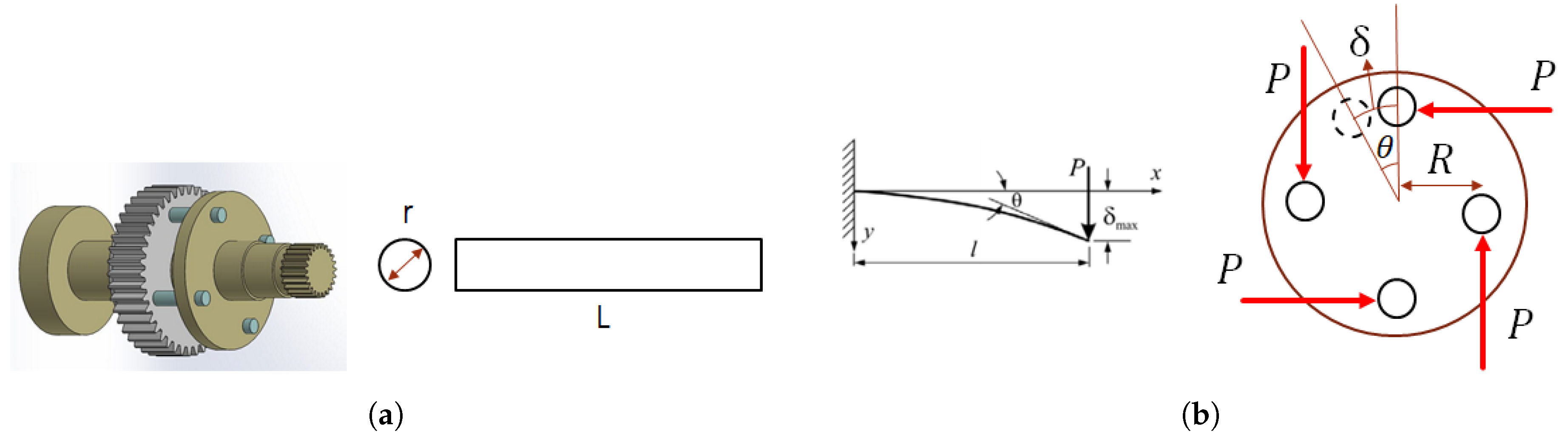
The elastic actuator is developed by modification on a standard robot servo. The standard robot servo, which is a traditional rigid actuator and used in many fields from robotics to hobby tools, has been transformed into a rigid actuator without changing the dimensions. In this way, it will be possible to apply the elastic actuator to the existing robot platforms without any design changes. For this purpose, the servo motor system whose basic components are shown in
Figure 1 has been modified.
In order to turn the analog or digital robot servo actuator into a stiffness adjustable elastic actuator, the mechanical structure and operating principle of the servo actuator has been first examined. Standard robot servos are simple mechatronic elements that can be directed to the desired angular position by means of an analog or digital measuring device connected to the output shaft. The rigid servo actuators are designed to orientate to the desired position and maintain their position as long as no new command is received. Inside the servo actuators there is a DC motor which enables the actuator to move. Apart from this motor, there is a gear mechanism, a potentiometer (or encoder) connected to the output shaft and a motor drive circuit. The potentiometer or encoder measures the rotation angle of the motor shaft. The potentiometer and output shaft rotate together as the DC motor and the associated gear system move and the control circuit drives the motor by comparing the position of the actuator with the desired position. In this way, standard robot servos operate without the need for an external motor drive.
The design was started by modeling the standard servo actuator in computer environment. To create an elastic actuator mechanism, the last gear that transfers the torque from the DC motor to the output shaft has been selected for elastic element placement (Shown by arrow in
Figure 1). First, the portions where the output gear receives and transmits torque are separated and divided into two parts as shown in the figure. Elastic coupling elements (four-leaf spring) are added between these two parts to form an elastic connection. The leaf springs are sized considering the criterion of not changing the dimensions of the servo actuator. The main objective in the use of leaf springs is to control the stiffness by directly changing the spring characteristic instead of changing the spring pre-tension or the transmission ratio to change the stiffness. Therefore, a design based on the principle of changing the active spring length is adopted to change the spring stiffness and cantilever beams are the most suitable choice for this mechanism. For this purpose, the output shaft and gear used as a single element is separated from each other and four cantilever beams are connected together by an elastic clutch mechanism. As shown in
Figure 2, when the clutch length is zero, the system acts as a rigid actuator and when the clutch length is set to the longest length allowed by the design, the actuator acts as an elastic actuator. Using a simple mathematical model, the rotational stiffness of this elastic coupling on the output shaft can be calculated.
The output gear and the output shaft are formed into two separate parts, which are connected to each other by four cantilever beams. This change in the current design is shown in
Figure 1. As can be seen from the figure, four elastic beams are positioned on this last gear by opening the slots on the last gear which takes the moment from the gear mechanism. The length of the shaft which transmits the torque to the output is extended and a section is formed at the bottom for the bearing. This part also depends on the potentiometer for position measurement. In the upper part, a cylindrical stage of the diameter of the output gear is formed on the output shaft to form a plane to which the elastic beams are connected. The distance of this section determines the constraints of the active spring (beam) length. In this mechanism, the gear which transmits the moment is fixed in the vertical direction and the output shaft which takes the moment from the gear mechanism moves up and down to change the active spring length. In order to make the hardness adjustment of the mechanism in a healthy way, an adjustment mechanism has been developed and the moving gear has been mounted on this adjustment mechanism. The design of the adjustment mechanism is shown in
Figure 2. In this mechanism, when the adjustment lever is turned, the gear to which it is connected rotates and the circular movement of the rack gear turns into linear movement and the adjustment mechanism moves in the vertical direction. By means of this mechanism, the gear and output shaft are elastically connected to each other by four cantilever beams (springs), resulting in an adjustable elastic actuator mechanism.
The cantilever beams used in the stiffness adjustable actuator design are only forced to bend as shown in
Figure 3. Therefore, the problem of bending of cantilever beams with circular cross-section should be examined for the stiffness values.
Bending stiffness in cantilever beams is a standard for measuring deformability. It is based on two important properties—the elastic modulus of the material and the moment of inertia of the section. The displacement of the end point in a cantilever beam forced by the force
P is given by Equation (
1).
Each cantilever beam positioned as far as
R is forced by this
P force. This means that the elastic clutch transmits a moment of magnitude (Equation (
2));
Furthermore, the following expression can be written between the displacement of the end points of the cantilever beams and the relative angle of rotation of the elastic joint from the geometric relations (Equation (
3)).
When Equations (
1)–(
3) are evaluated together, the following statement gives the variation of the stiffness of the elastic joint with the clutch length (Equation (
4)).
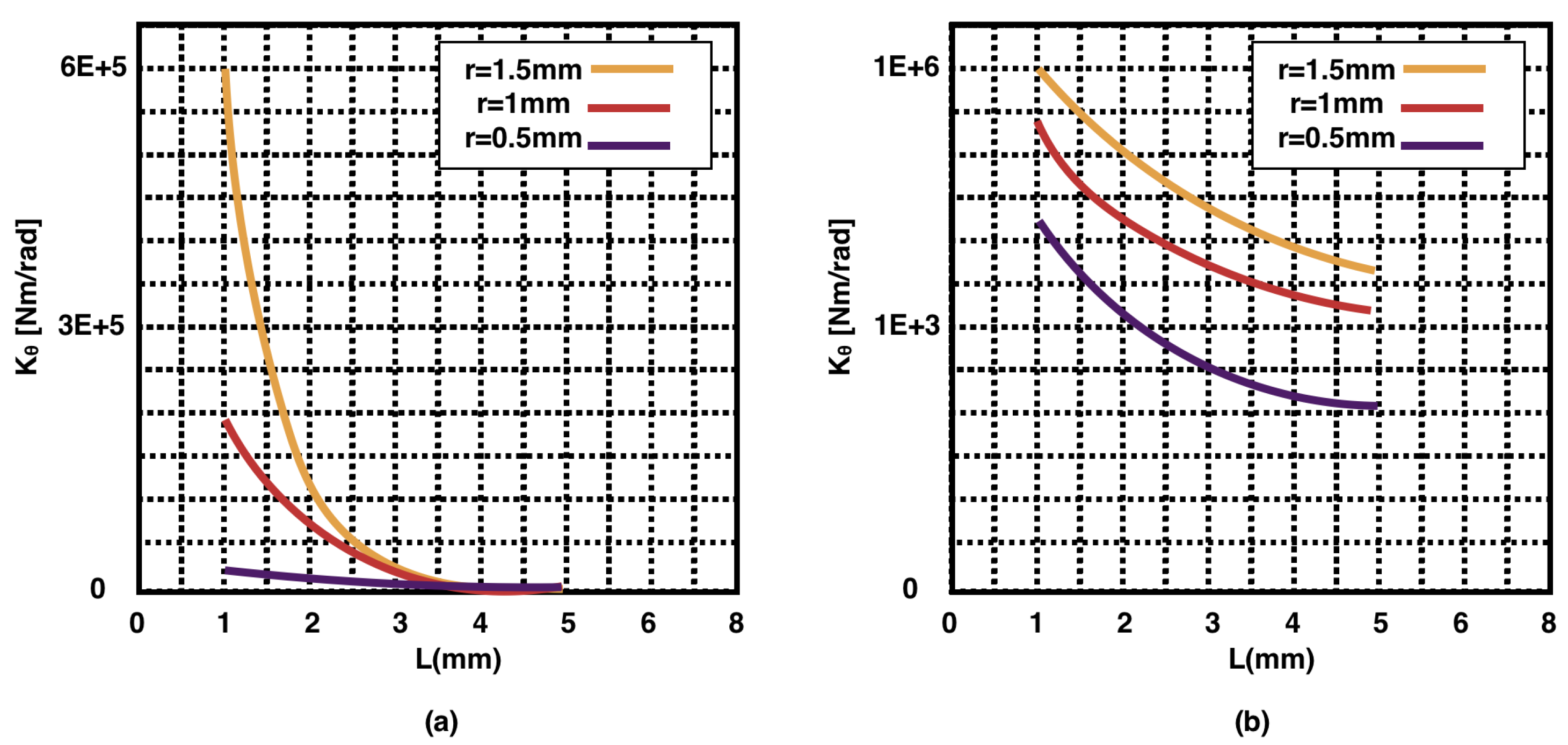
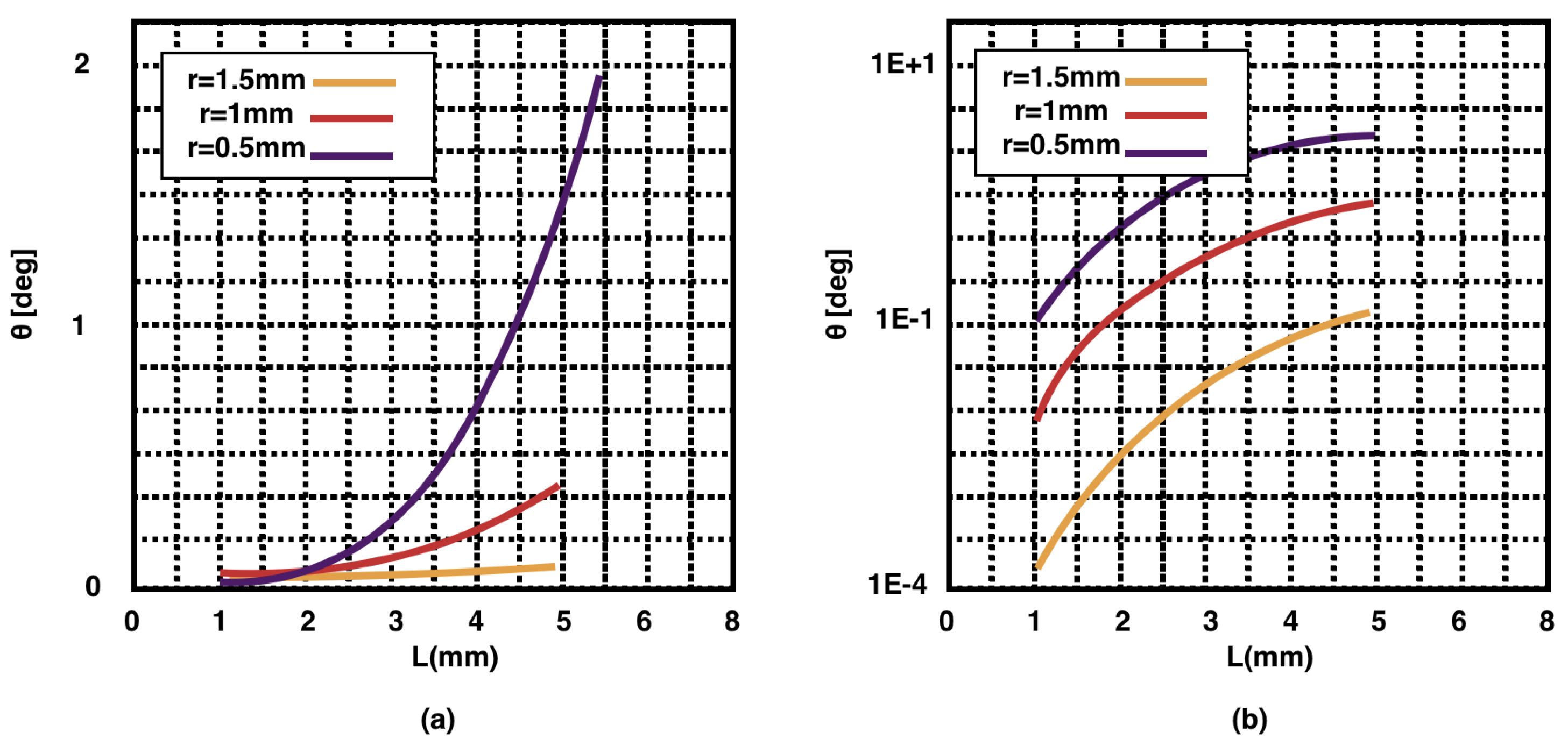
Here, represents the total torsional stiffness of the elastic clutch, E represents the modulus of elasticity of the beam material, I represents the section moment of inertia of the beams (), R represents the distance from the center of the gear to center of the four beams and L represents the active clutch length.
2.2. Trade-Off between Backlash and Torque Capacity
The design process of any mechanical system, including an actuator, inevitably contains some trade-offs. With this actuator, the most predominant trade-off is the one between backlash and the torque capacity. The reason this trade-off is so fundamental is the fact that it needs to be determined at a high-level decision-making level by the designer to fulfill certain performance criteria but at the same time, it affects almost all other design parameters in a very detailed fashion, for instance, dimensions of other components.
The torque capacity refers to how much torque this actuator can handle. As the electric motor, gearbox and the stiffness adjustment module are connected in a series fashion, the torque capacity of the whole actuator is determined by the lowest torque capacity among these series connected elements. We always have the possibility to use stronger electric motors and gearboxes if needed, however, it is the stiffness adjustment mechanism that needs to be carefully designed to satisfy the required torque capacity.
Considering the stiffness adjustment mechanisms, proposed in this work, the torque capacity can be manifested through bending capacity of the cantilever beams. This bending of the beam is restricted by two factors in our design—(1) the material of the cantilever beam; and (2) the circular slots on the clutch mechanism that hold and move along the cantilever beams to adjust their effective lengths. Again, we always have the possibility of using stronger materials for the cantilever beams to enhance their torque capacities. However, the vital design parameter is the size of the slots that hold the cantilever beams.
The cantilever beams have cross-section circular profiles. The difference between the radius of the circular profile of the cantilever beams and the one of the slots on the clutch, can determine how much the beam is allowed to deflect, that is, the bending capacity and eventually the torque capacity. The larger is this difference, the higher is the torque capacity. However, this difference in the two circular profiles would also lead to having backlash at the output link. Imagine the case where the output link is not deflected and thus cantilever beams are straight. Now, if an external torque is applied at the output link, it causes the output link to “freely” rotates, as there is a gap between the cantilever beams and the circular slots. This free rotation of the output link is in fact the backlash of the output link.
In order to analyse this trade-off, first we need to mathematically formulate the bending capacity of the cantilever. The bending of the cantilever leads to the output link rotation that is denoted by
. The cantilever’s deflection
due to an external and perpendicular force applied at the tip of the beam, is nonlinear. This means that the displacement of each segment of the beam perpendicular to the axis of the beam is not linearly proportional to the beam’s length. Therefore, the deflected beam deflects as a curve rather than a straight line. However, in order to simplify the formulation, we consider a linear deflection. Therefore, the maximum bending capacity can be presented as:
where
is the vertical displacement of the tip of the lever. Now, let’s consider the thickness of the clutch as
, then the minimum radius for the circular slot on the clutch
should be:
Now, with this circular slot, let’s consider when the cantilever beam is not deflected and the clutch is located at distance
x from the output of the gearbox. The backlash
is then the amount of free rotation of the output link before the beam starts bending:
The decision is then up to the designer to determine the radius of the circular slot on the clutch, based on the requirements of the desired applications.
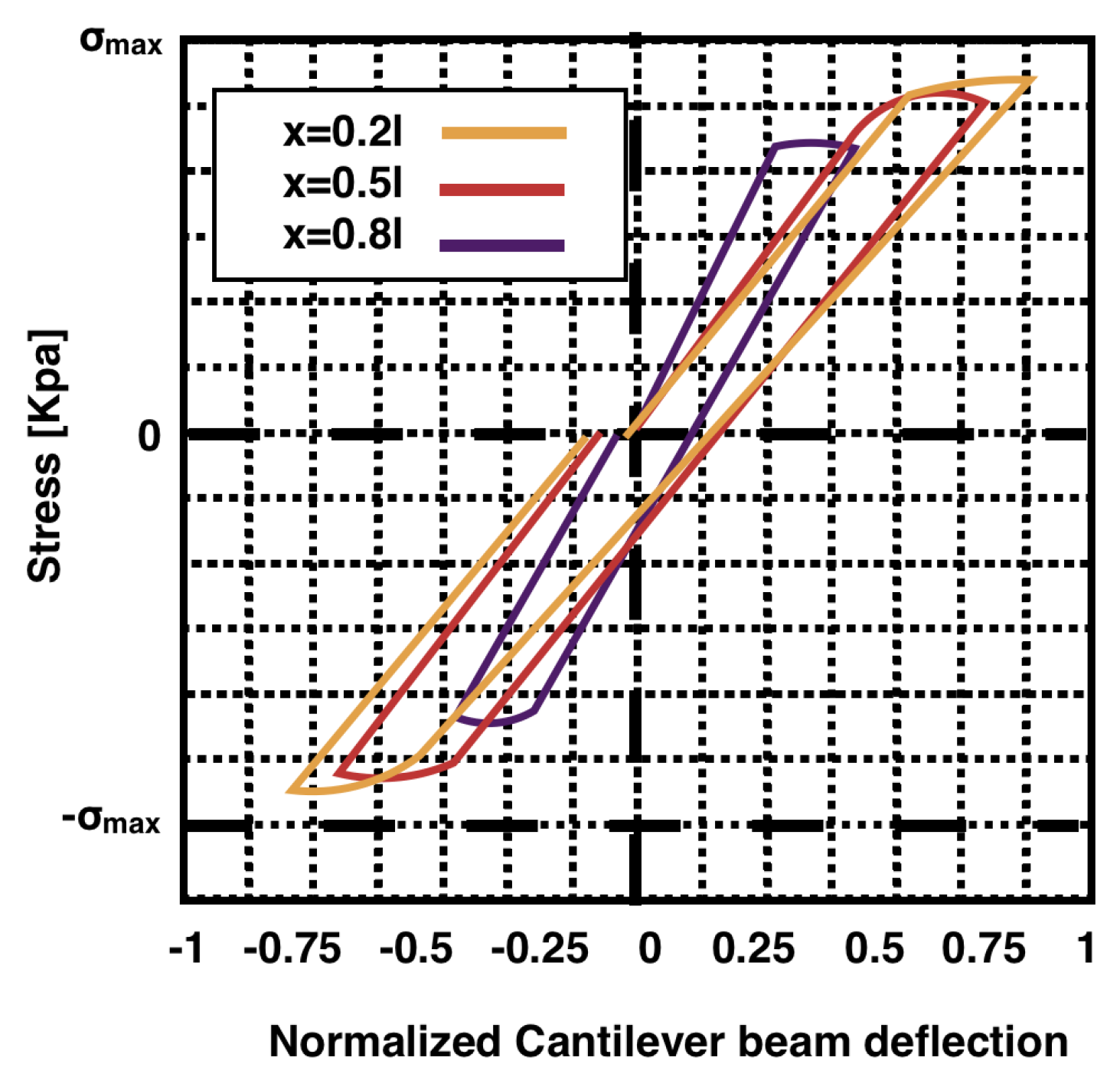
2.3. Hysteresis Analysis of the Cantilever Beam
Another important design parameter to consider is the hysteresis of the cantilever beam, when it is subjected to periodic forces. Let’s consider there is zero backlash so the beam is always in contact with the clutch and bends symmetrically along its axis due to the period force. When the force is increasing in let’s say positive direction, the beam is going to deflect in a positive direction, though in a nonlinear fashion. However, in order to simplify the analysis, we consider a linear force to deflection profile for the beam. when the force reaches its maximum, it will decreases back to zero and starts bending the beam in the opposite direction, that is, negative, and then goes back to zero once it reaches its minimum level. However, the beam deflection does not necessarily reaches its zero deflection once the force is zero. This is due to the hysteresis of the beam which affects its periodic behavior. Therefore, the beam deflection always lags the force in the periodic scenarios and thus the beam behaviour should be carefully taken into account to avoid errors in controlling the output link trajectory.
The hysteresis analysis depends on the geometry, material properties of the cantilever beam and most importantly, the friction between the cantilever beam and the clutch. Considering the geometry and material of the beam for this actuator, we performed a simulated hysteresis analysis for a generic periodic force that leads to a periodic stress at the beam. We consider the kinetic friction force between the clutch and the beam as there is in fact relative displacement between the two during the bending process. The friction force is a function of perpendicular force and kinetic friction coefficient. The kinetic friction coefficient is assumed to be 0.4, considering the beam is made of Stainless Steel and the clutch from aluminum. The perpendicular force depends on the external torque and the location of the clutch along the beam, that is,
x. The simulation results have been plotted in
Figure 4 for
,
and
. The vertical axis shows the perpendicular stress and the horizontal axis shows the beam deflection normalized by its maximum value.
4. Experimental Results
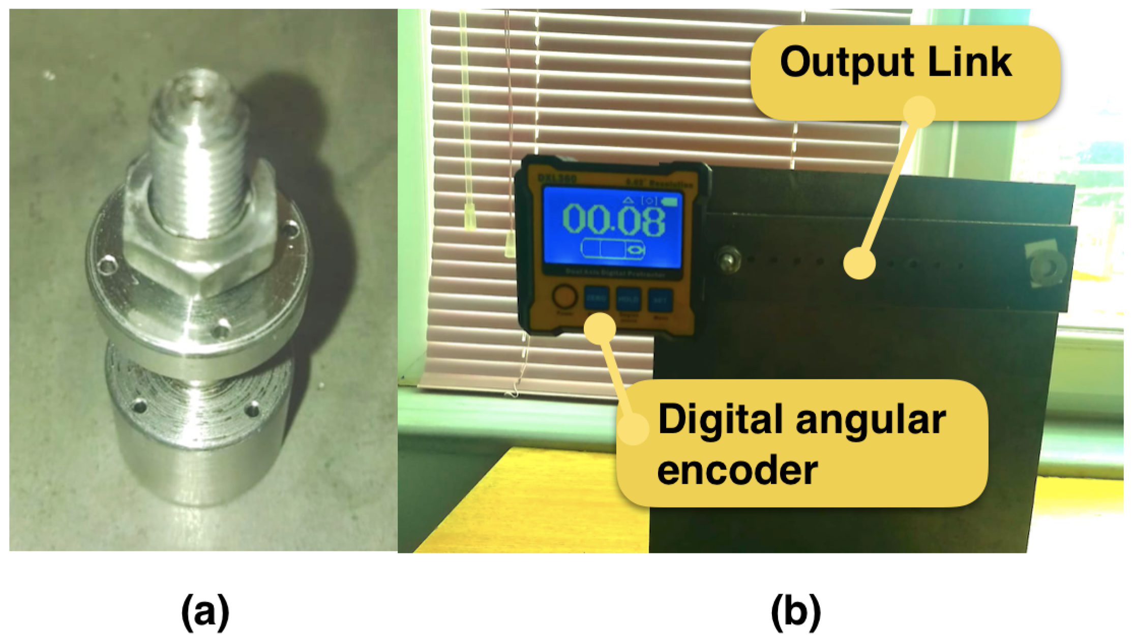
Stainless steel was used as the material for the leaf springs. Radius of each beam was set to 0.5 mm, with the overall length of 10 mm. However, the maximum length that could be used as the cantilever was 8 mm, leaving around 2 mm to be the part of the beam that handles the force. Commercial planetary gears were used as transmission in different parts of the actuators. Dynamixel AX-12A Robot Actuators was used as the servos, with 0.3 degree resolution integrated encoder and current sensor. The force was measured through a digital scale attached to the output link.
The controller and the driver of the implemented actuator were custom control boards based on the Texas–Luminary DSP. These controllers performed the regulation of the motions of the two motors at 1 kHz. The control system is based on a position controller, where the inputs are the desired joint stiffness and the desired link trajectory. The setup is shown in
Figure 7.
The focus of this work is on the stiffness adjustment mechanism rather than the whole VSA system. It is very true that the actuator and transmission system, indeed affect the performance and stiffness properties of the output link. However, our goal is to introduce a general stiffness adjustment mechanism that can be simply added to commercially available actuators. In this sense, we only focus on the stiffness adjustment mechanism to show its performance regarding the stiffness range and how it affects the trajectory of the output link.
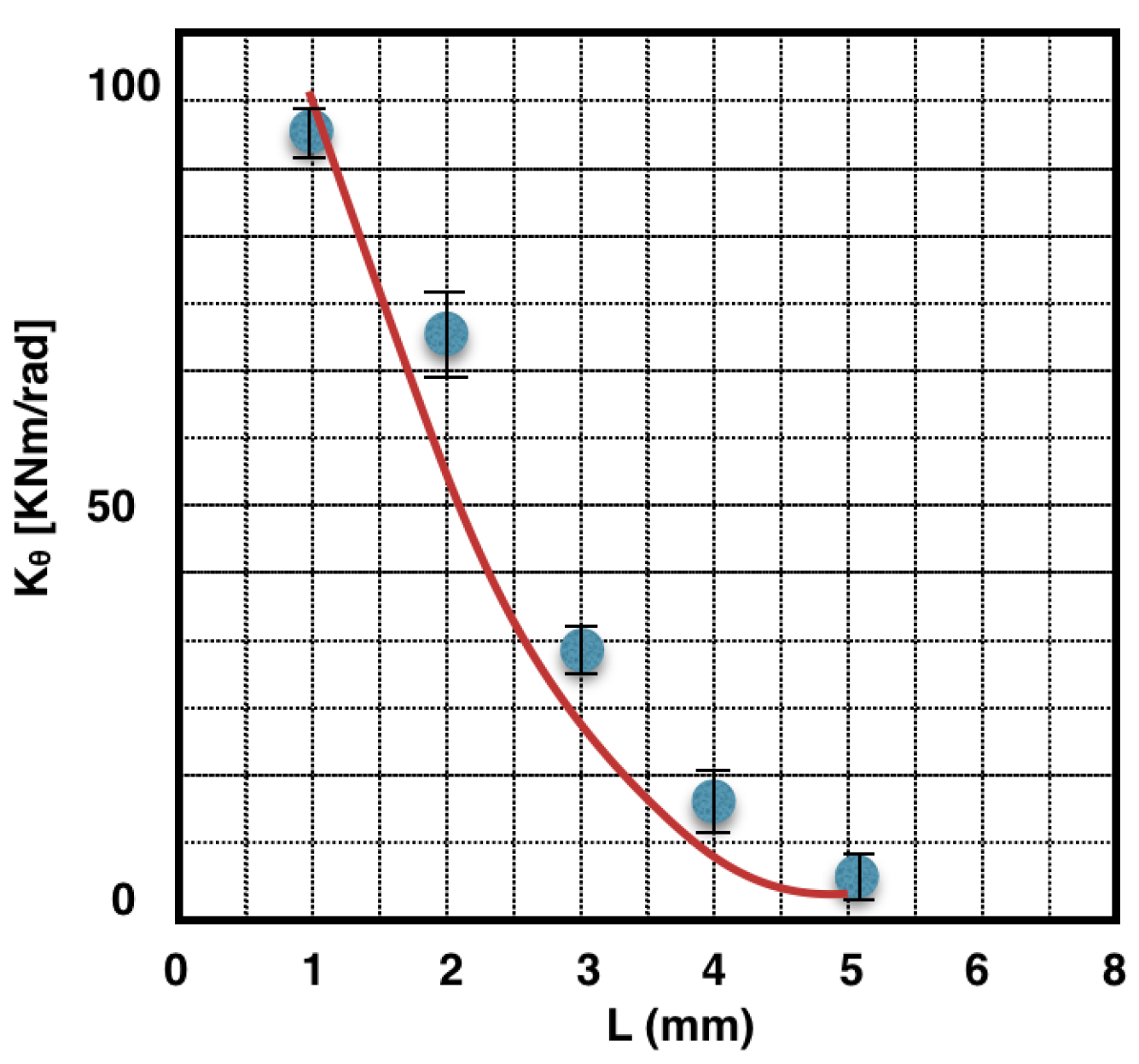
To show the capability of the proposed stiffness adjustment mechanism to regulate the stiffness, the length of the cantilever was set to different values, while an external load was applied at the output link. The angular deflections were measured through the encoders while the external torque was calculated based on the applied weight and the distance from the point where the weight was hanged to the output link and the center of rotation. Stiffness was then calculated as the ration between the applied torque and resultant angular deflection. The results are presented in
Figure 8.
The maximum external load that was applied to the output link was 20 Nm that caused deflection around 0.0002 rad with L = 1 mm and 0.2 rad when L = 5 mm. This shows the stiffness adjustment module is capable of handling the stall torque of the Dynamixel AX-12A while the maximum angular deflection of the output link is 0.2 rad.
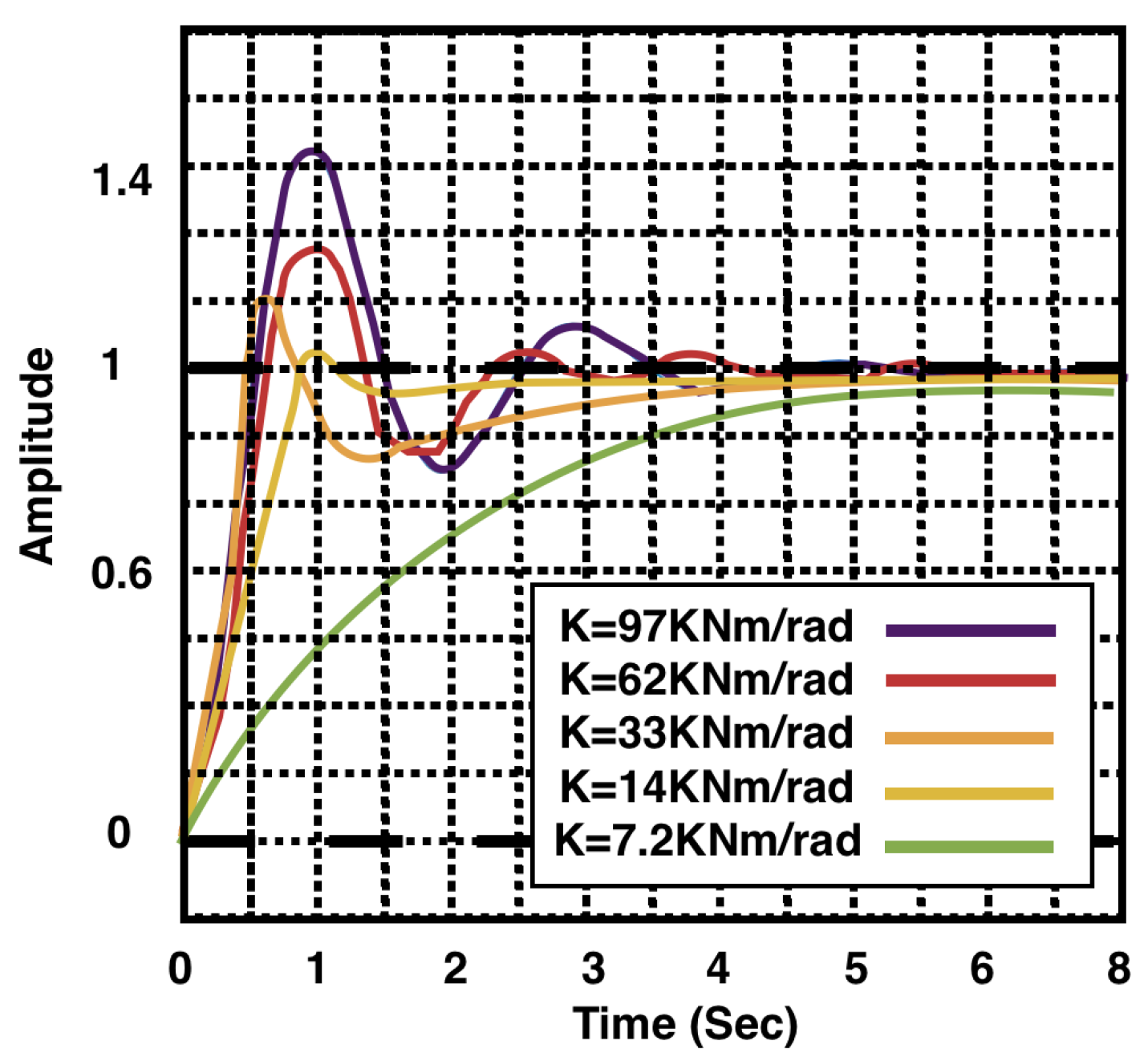
In another set of experiments, and to show the performance of the actuator to follow a trajectory, the length of the cantilever was set to different values while an step signal was commanded to the position motor and the motion of output link was tracked by the encoder. The performance is depicted in
Figure 9, where the trajectory of the output link has been processed through a low-pass filter at 4 Hz and normalized by its steady-state value.
5. Discussion and Conclusions
Despite the face that VSAs have the ability to regulate the output stiffness of their link, their infusion into robotics applications is still limited and far behind the case of SEAs. The reason is due to the extra complexity that having two motors will add not only to the mechanical structure but also to the control aspect of the whole system. For more detailed analysis please refer to Reference [
8].
SEAs, however, are not always the best choice, when compliant behaviours are desired. The reason is due to their fixed and not adjustable stiffness levels, that might not be the optimum stiffness value for a particular application. A non-optimum stiffness level not only affects the trajectory tracking performance of the actuator but would also dramatically increases the total energy consumption by the actuator in periodic motions.
For many robotic applications, the ideal scenario is an actuator that is compliant, while its level of compliance can be adjusted without a need to add additional motor.
In this study, a new stiffness adjustable elastic actuator design was developed. In the design, the bending problem was solved for four cantilever beams acting as leaf springs. The stiffness and the angular deformation values of the elastic clutch mechanism were obtained analytically. The elastic actuator introduced in this study is based on a standard servo actuator and is unchanged in size. The stiffness adjustment mechanism of the present design consists of a manually controlled adjustment bolt. In other words, the stiffness can not be changed while the system is in motion. However, by connecting a servo actuator to the adjustment lever, a design can be obtained which can change the stiffness value of the actuator while the system is in motion. The present study focuses on the design and modeling of the hardness mechanism of the actuator, and it is aimed to carry out studies on the control of the actuator and to verify the analytical calculations with experiments in the future studies. This actuator design is considered to be an important alternative to existing designs in that it is simple enough to allow for the widespread use of adjustable elastic actuators.


