Article

Modeling of Attractive Force by Magnetic Wheel Used for Mobile Robot

Department of Mechatronics, Chungnam National University, Daejeon 34134, Korea
*
Author to whom correspondence should be addressed.
Actuators 2020, 9(3), 67; https://doi.org/10.3390/act9030067
Submission received: 20 July 2020 / Revised: 5 August 2020 / Accepted: 7 August 2020 / Published: 9 August 2020
(This article belongs to the Special Issue Actuators for System Identification, Vibration Analysis, and Control)

Abstract

:
Mobile robots that are required to climb inclined ferromagnetic surfaces typically employ magnetic wheels. In order to design magnetic wheels and to properly size the permanent magnet as magnetizing source without the need for finite element analyses, a model that predicts the attractive magnetic force is necessary. In this paper, an analytical force model is derived by estimating the reluctance between the wheel and the surface. A magnetic circuit is constructed, incorporating the leakage flux from the side of the wheel. The model is validated against the results from finite element analyses and measurements from a test rig and a wheel prototype. Within the limitations of the model, it can adequately predict the force and can be used for initial design of magnetic wheels.

1. Introduction

Robots that can climb vertical walls and hold on to surface at any angles are required for many mission-critical applications in hazardous environments such as inspection of pipes and reactor vessels in nuclear power plant, welding in ship building, and inspection of dry storage casks for spent fuel rods. To maintain robot positions on inclined surfaces, two mechanisms are typically used: pneumatic suction [1] or magnetic wheels [2,3,4,5]. In terms of size and the ability to maintain its position without power, a robot with magnetic wheels is preferable to the one with suction pads. For irregular ferromagnetic surfaces, magnetic wheels are the only option.
In most cases, a magnetic wheel consists of a permanent magnet (PM) as a magnetizing source and ferromagnetic parts for flux guidance and for ensuring enough traction surface. In a typical electric machine, PM is used for continuous rotation [6]. In contrast, the role of PM in a magnetic wheel is to generate the magnetic field that is needed to produce required attractive forces. The first step in designing a magnetic wheel is to determine the size of the wheel and PM. Past efforts to design a magnetic wheel include a rule-of-thumb approach [7] and finite element analyses (FEA) [2,3]. Normally, the rule-of-thumb method results in a bulky design due to safety factors that are necessary to accommodate the uncertainty of the method. Finite element calculations take a very long time for design iterations or optimizations especially for the inherently three-dimensional wheel geometry.
An analytical model that relates wheel parameters to load capacity would be very convenient for designing magnetic wheels. However, it is rather difficult to accurately model the magnetic field distribution between the wheel and surface due to rapid change in field around the contact area. For example, Kindl et al. [8] proposed a magnetic force model by assuming the magnetizing intensity inside PM and by neglecting the side leakages. Since the field distribution changes too rapidly between the wheel and the surface, they assumed a very limited area of contact with uniform field which is clearly unrealistic. Even the calculations by FEA can be misleading if the meshing around contact area is not dense enough.
In this paper, we propose a model that predicts the attractive force of a magnetic wheel pair by combining analytical approach with magnetic circuit method. This model estimates the reluctance of the air gap between the wheel and surface based on flux lines conforming to the boundary conditions of field equations. The estimated reluctances are used to determine the magnetomotive force (MMF) contributing to force generation. The validity of the model is verified through FEA and tests.

2. Derivation of Force Model

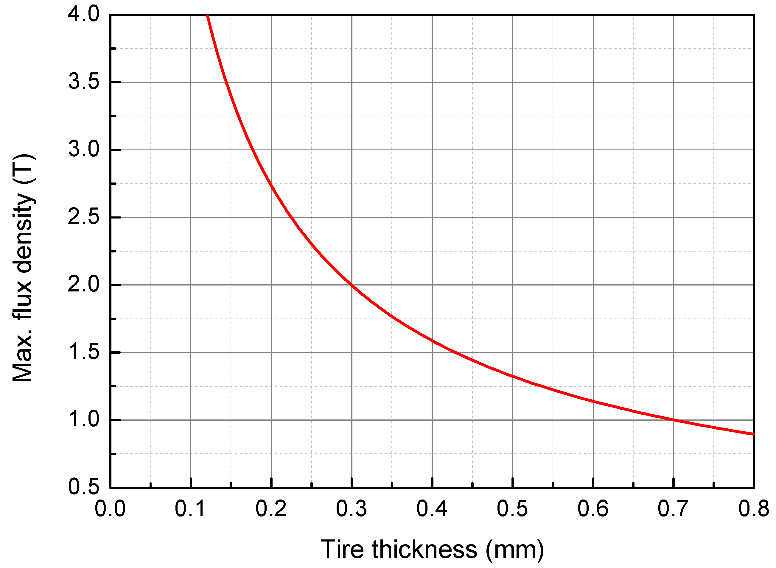
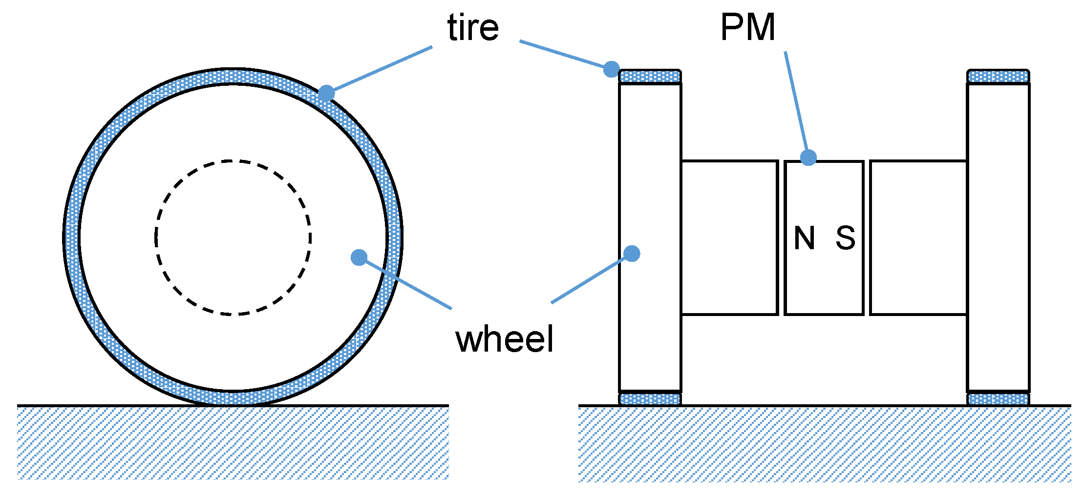
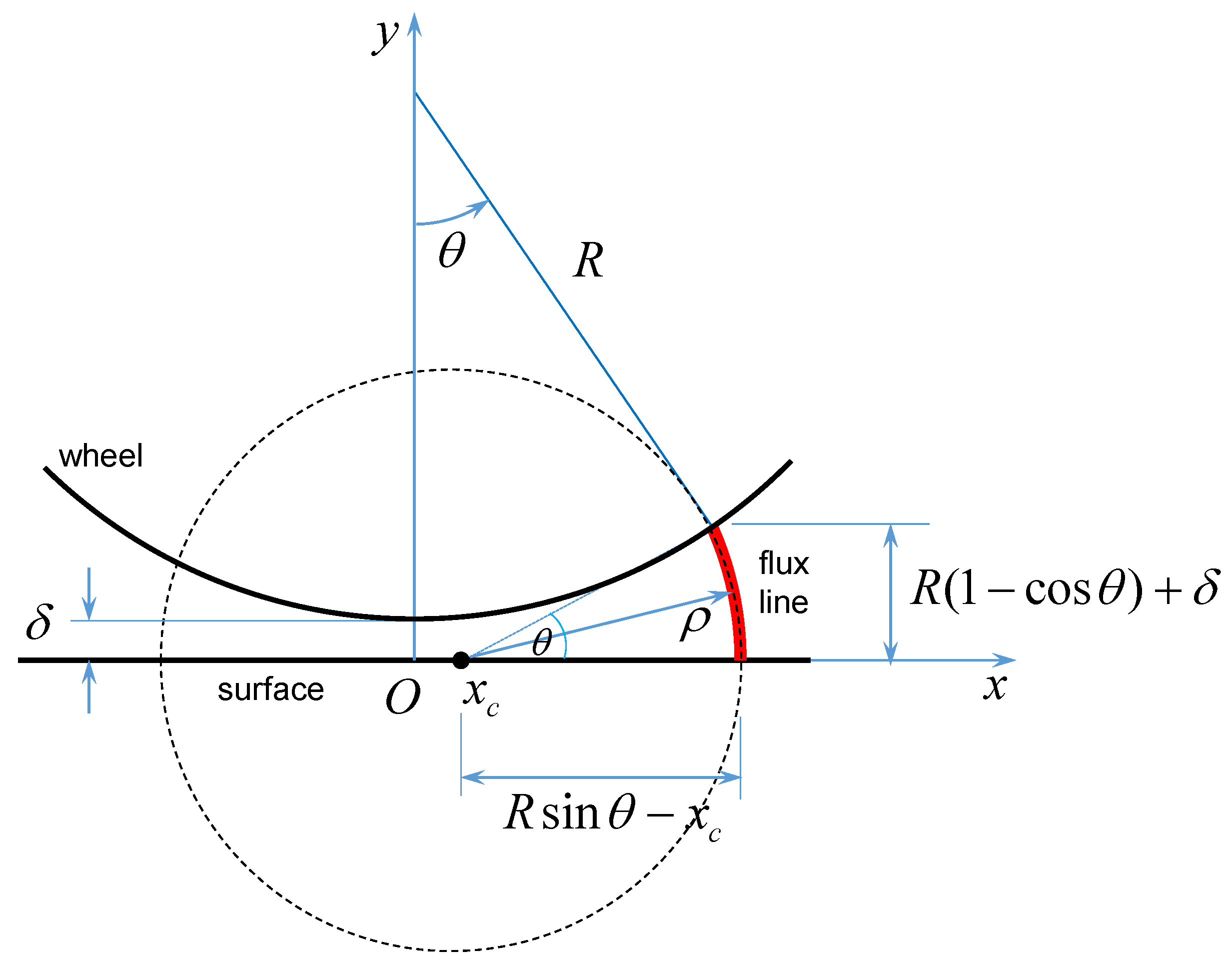
2.1. Reluctance Estimation

Shown in Figure 1 is the simplified structure of the magnetic wheel containing essential elements. It consists of two ferromagnetic wheels joined by an axle. A permanent magnet is located at the center of the axle. As shown, a closed magnetic loop is formed, and wheels are attracted to the surface. If the magnet is rotated by 90 degrees perpendicular to the axle, the magnetic loop breaks open, resulting in detached state. Optional flexible tires can increase traction force by providing a higher friction coefficient and larger contact area.
An analytical force model would be convenient for designing the wheels and sizing the PM. Kindl et al. [8] proposed such a model. However, they assumed that the flux lines between the wheel and the floor are linear, which violates the boundary conditions of field equations if the ferromagnetic material has high permeability. They considered a very limited area of contact where the field is uniform, which is unrealistic since the field changes rapidly at the nearest point between the wheel and the surface. They also neglected the side leakages which can be significant.
This paper derives the force model by estimating the reluctance between the circumferential surface of the wheel and the floor surface more accurately than the previous research. It is assumed that the flux lines between the wheel and the floor follow circular paths which satisfy the boundary conditions. There can be geometrically shorter paths than circular arcs, but the path must be continuously differentiable.
To estimate the reluctance (or permeance), a coordinate system is defined as shown in Figure 2, where δ is the minimal distance between the wheel and the floor surface to account for the tire thickness, and R is the radius of the wheel. The x-axis lies on the floor surface. The origin of x-axis is the point that is closest to the wheel. The flux line at an arbitrary angle θ would be a circular arc, the center of which lies on the x-axis. The center of the arc is denoted by x c , while ρ is the radius of the arc. Using the geometric relations as shown in Figure 2, it is observed that
R sin θ x c R ( 1 cos θ ) + δ = cos θ sin θ .
Rearranging this, we get
x c = R ( R + δ ) cos θ sin θ ,
as well as
ρ = R ( 1 cos θ ) + δ sin θ .
Along the vertical axis ( θ = 0 ), both x c and ρ become infinity, which means that the path is straight. This singularity disappears in the force model. The differential permeance at the angle θ is
d P g = μ 0 w R d θ ρ θ ,
where w is the axial width of the disk. The total permeance can be obtained by integrating the differential permeance as
P g = 2 0 θ m μ 0 sin θ d θ θ [ 1 cos θ + δ / R ] ,
where θ m is the angle limit beyond which the flux density falls off below a negligible value.
Due to the nature of wheel geometry, the side leakage is expected to be significant, as depicted in Figure 3. In order to estimate the side leakage, an equivalent air gap is defined as
g eff = 2 μ 0 R sin θ m P g .
This equivalent air gap can be thought as the uniform air gap having the same permeance as the wheel. Then, using the method of estimating the side leakage for toothed structures [9], the side leakage permeance is approximated as
P sl = 2 μ 0 w π ln 1 + π X 2 g eff ,
where X is the extent outside of which the leakage flux is negligible. Then the reluctance of the wheel air gap can be written as
R g = 1 P g + P sl .

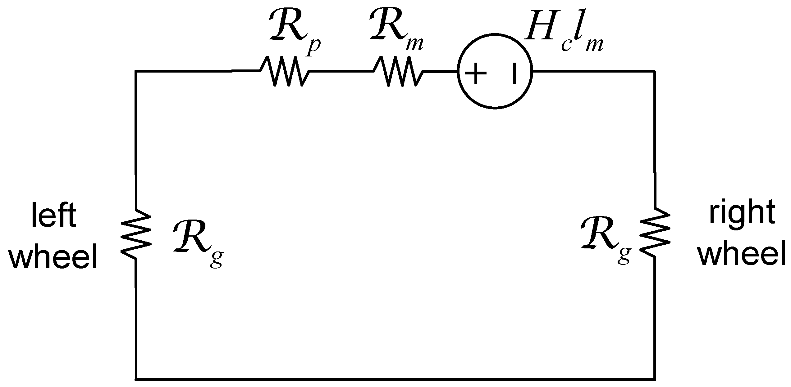
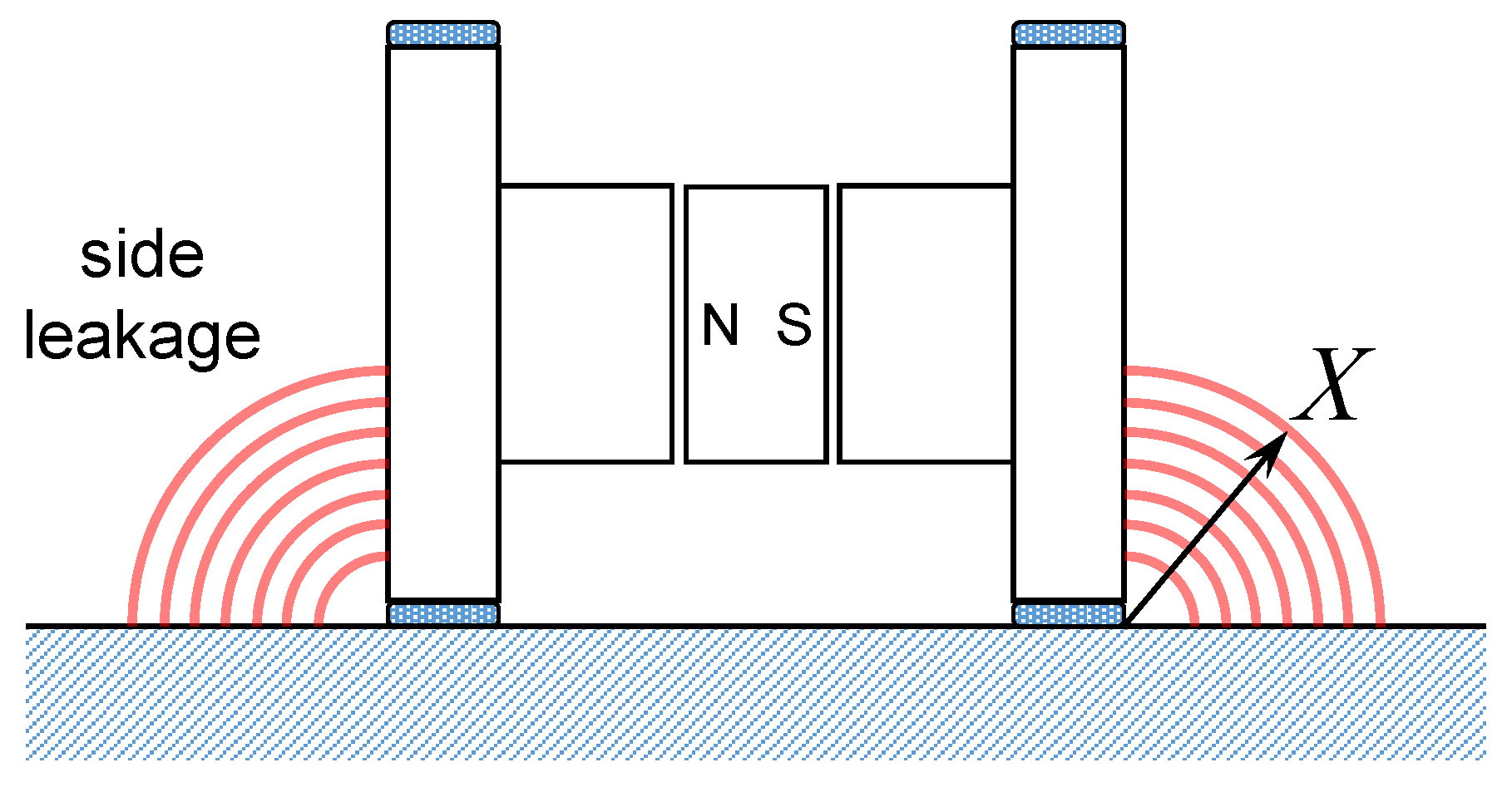
2.2. Magnetic Circuit

The source of the magnetic field is the permanent magnet (PM) at the center of the axle. The choice of material for PM depends on several factors. Firstly, the material must have high specific energy in order to minimize the weight of the wheel. In addition, it should withstand the environment where the mobile robot operates. Lastly, the magnetic design becomes easier if the demagnetization curve is linear. Materials such as Alnico have nonlinear demagnetization curve, and make it impossible to use magnetic circuit approach. Further, they are fragile and easily demagnetizable at low temperatures.
Rare-earth PMs such as neodymium-iron-boron (NdFeB) are ideal for our purposes, as they have very high specific energy and almost linear demagnetization characteristics with the permeability very close to that of air. Therefore, the magnetic wheel can be represented by a circuit as shown in Figure 4. The reluctances of the disk and the floor surface are neglected, assuming they are made of infinitely permeable materials. The clearance between the PM and axle for the rotation of PM contributes to the circuit as a reluctance, R p . The reluctance of PM is obtained by
R m = l m μ m A m ,
where l m is the PM length, A m the cross-sectional area, μ m the permeability of PM which is assumed to be the same as μ 0 . The magnetomotive force (MMF) applied to each wheel can be written as
F m = R g R m + R p + 2 R g · H c l m ,
where H c is the coercitivity of PM.

2.3. Attractive Magnetic Force

Since the MMF acting on the wheel is explicitly obtained, it is possible to find the flux density distribution along the perimeter of the wheel. In contrast, the previous research [8] treated F m as unknown and had to assume a value on the operating line. Using (9), the magnetic flux density at the angle of θ can then be estimated by
B g = μ 0 F m ρ θ .
Finally, the attractive force can be obtained by integrating the Maxwell stress tensor around the disks, which can be written as
F = 1 2 μ 0 S B n 2 n ^ d s ,
where B n is the component of the flux density vector normal to the surface [10]. Using (10) and (11), the attractive force can be written as
F y = 2 μ 0 R 0 θ m F m 2 sin 2 θ cos θ θ 2 [ 1 cos θ + δ / R ] 2 d θ .

3. Validation of Force Model

3.1. Numerical Validation

In order to verify the validity of the force model, three-dimensional (3D) finite element analyses (FEA) are carried out. A commercial solver, MAXWELL3D (Ansys Inc., Canonsburg, PA, USA) is used for this purpose. A wheel pair is first designed for analysis. Table 1 summarizes key parameters. The required load capacity of the wheel pair is 75 N. The permanent magnet is made of NdFeB 50H grade having the coercivity of 995 kA/m.
One case of FEA is shown in Figure 5. The FEA model consists of 75,485 tetrahedra elements. It takes approximately 39 minutes on a PC (i9-7920X CPU, 2.9 GHz, 64 GB RAM). It can be seen that the highest flux density is near the contact point of the wheel with the surface, as expected. When carrying out FEA, it is important to check if the meshing around the contact point is dense enough that the steep flux gradient is adequately calculated. In addition, the material property of ferromagnetic parts such as wheel disks and axle must include magnetic saturation. Otherwise, the results of FEA would be unrealistic.

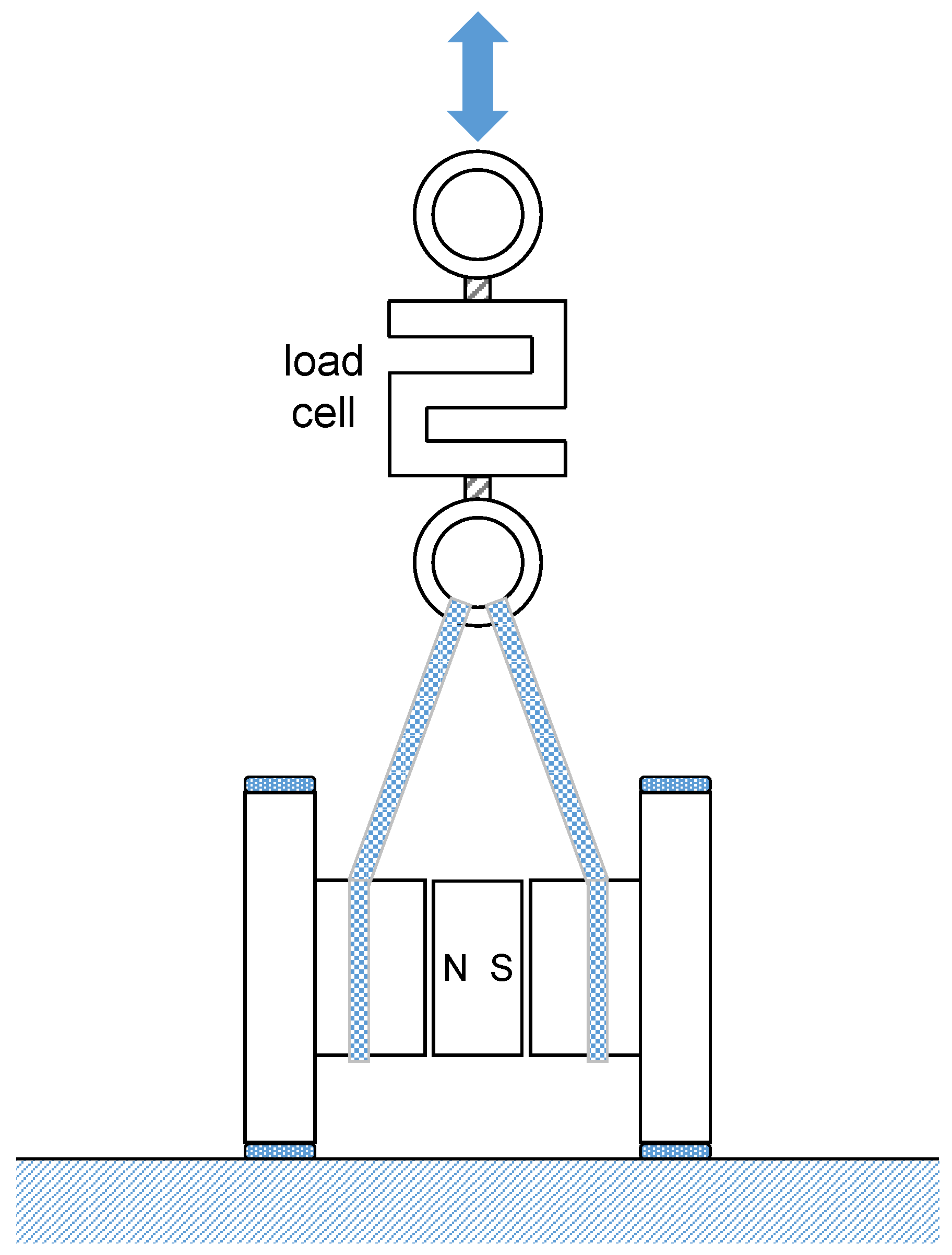
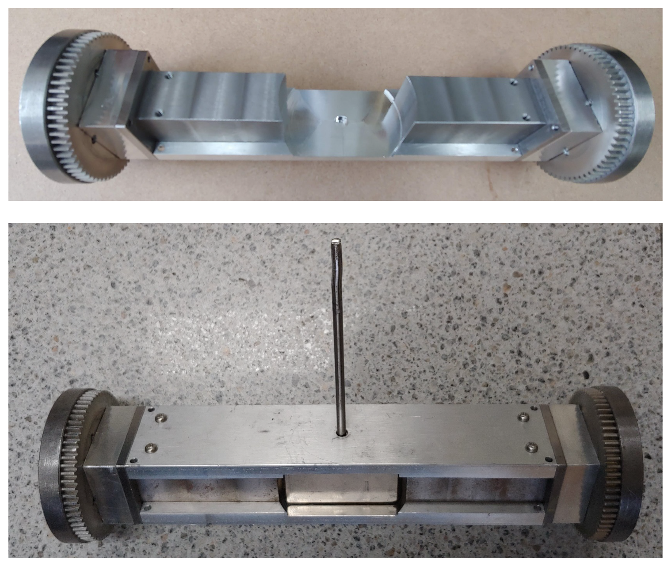
3.2. Test Setup for Experimental Validation

To experimentally validate the force model, a prototype of wheel pair and test rig are built. Pictures of the prototype are shown in Figure 6. The prototype has the same dimensions as the one used in FEA except several modifications that are necessary for actuating the permanent magnet and rotating the wheels. The ferromagnetic parts are made of 1010 steel.
The attractive force of the wheel pair is measured using a test setup depicted in Figure 7. The wheel pair is connected to a load cell (SBA-200L, CAS, Seoul, Korea) using a rope. In order to simulate tire and to maintain constant air gap between the wheels and the surface, sheets of plain paper are inserted in the gap. The thickness of one sheet is measured to be 0.101 mm. While the wheel pair is attached to the surface with several sheets of paper inserted in the gap, the load cell is slowly pulled up using a crane. The force measurement of the load cell is recorded just when the wheels are detached from the surface. It is important to use the peak detect mode of the load cell indicator, since the force diminishes rapidly, as soon as the wheels are detached. The test is repeated 10 times. Another measurements with different air gaps are carried out with different number of sheets.

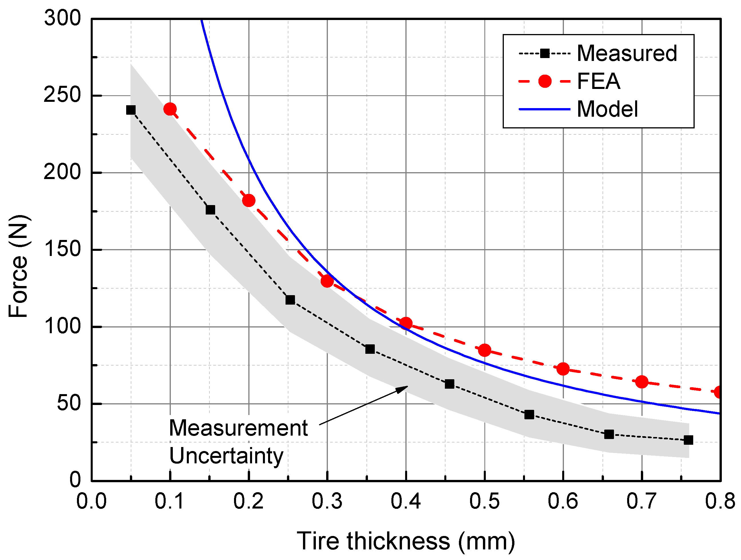
3.3. Validation Results

Figure 8 summarizes the results of both numerical and experimental validation. The measurements are displayed with uncertainty. The next section discusses how the measurement uncertainty is estimated. When compared to the results from FEA, the model overestimates the force if the tire thickness is small, and shows slight underestimation if the tire thickness is more than 0.4 mm. The model consistently overestimates the force when compared to measurements, although the model agrees better with the measurements than the results from FEA. At the design point of 0.4 mm tire thickness, the predicted force by the model is close to both FEA and measurements if measurement uncertainty is considered.

4. Discussions

As shown in Figure 8, the forces predicted by the model are a little different from the results from FEA and measurements. Several issues can be considered to account for the mismatch. First of all, the model is valid as long as the material is magnetically linear. In other words, the model is derived with an assumption that the flux density is below magnetic saturation. Figure 9 shows the maximum flux density calculated by the model. If the tire thickness (or air gap) is less than 0.3 mm, the flux density is over 2 T. Therefore, the model is not usable with very small tire thickness.
Another issue is the measurement uncertainty. To simulate the tire, sheets of paper are used. When 50 sheets are measured, the mean thickness is 0.101 mm with the standard deviation of 10.6 μ m. Therefore, the air gap (or tire thickness) has about 30% uncertainty with 95% confidence. Surface roughness also contributes to the uncertainty in tire thickness. Typical surface roughness through milling or turning is up to 6 μ m [11]. The combined surface roughness of wheel and surface can be more than 10 μ m. The measurement uncertainty shown in Figure 8 is based on the variation of paper thickness.
Lastly, the model ignores the reluctance of the ferromagnetic parts such as axle and wheels. The structure of the actual wheel pair is rather complex to rotate the wheel while maintaining flux path. The reason that the measured forces are lower than the model may be due to the reluctances of the ferromagnetic parts. This can be easily compensated by adding a reluctance in the magnetic circuit in Figure 4.

5. Conclusions

In this study, an analytical model that predicts attractive force of magnetic wheels is derived. The model is validated against finite element analyses and test results. Within the limitations of the model, it adequately predicts the force produced by the wheel pair. The main purpose of the model is for designing the wheels and for sizing the permanent magnet in order to produce the required load capacity. Test results support that the developed model satisfies this purpose and can be used at least for the initial design.

Author Contributions

Conceptualization, M.N. and Y.-W.P.; methodology, M.N.; software, S.H.P.; validation, E.K. and S.H.P.; investigation, Y.-W.P.; writing—original draft preparation, M.N.; writing—review and editing, Y.-W.P.; visualization, E.K. All authors have read and agreed to the published version of the manuscript.

Funding

This work was supported by the Korea Institute of Energy Technology Evaluation and Planning (KETEP) and the Ministry of Trade, Industry & Energy (MOTIE) of the Republic of Korea (No. 20171520101780).

Conflicts of Interest

The authors declare no conflict of interest.

References

  1. Briones, L.; Bustamante, P.; Serna, M.A. Robicen: A wall-climbing pneumatic robot for inspection in nuclear power plants. Robot Cim.-Int. Manuf. 1994, 11, 287–292. [Google Scholar] [CrossRef]
  2. Han, S.C.; Kim, J.; Yi, H.C. A novel design of permanent magnet wheel with induction pin for mobile robot. Int. J. Precis. Eng. Man. 2009, 10, 143. [Google Scholar] [CrossRef]
  3. Wu, M.; Gao, X.; Yan, W.; Fu, Z.; Zhao, Y.; Chen, S. New mechanism to pass obstacles for magnetic climbing robots with high payload, using only one motor for force-changing and wheel-lifting. Ind. Robot 2011, 38, 372–380. [Google Scholar] [CrossRef]
  4. Yoon, K.H.; Park, Y.W. Controllability of magnetic force in magnetic wheels. IEEE T. Magn. 2012, 48, 4046–4049. [Google Scholar] [CrossRef]
  5. Tâche, F.; Fischer, W.; Caprari, G.; Siegwart, R.; Moser, R.; Mondada, F. Magnebike: A magnetic wheeled robot with high mobility for inspecting complex-shaped structures. J. Field Robot 2009, 26, 453–476. [Google Scholar] [CrossRef]
  6. Sun, X.; Shi, Z.; Lei, G.; Guo, Y.; Zhu, J. Analysis and design optimization of a permanent magnet synchronous motor for a campus patrol electric vehicle. IEEE T. Ven. Technol. 2019, 68, 10535–10544. [Google Scholar] [CrossRef]
  7. Xu, Z.; Ma, P. A wall-climbing robot for labelling scale of oil tank’s volume. Robotica 2002, 20, 209–212. [Google Scholar] [CrossRef]
  8. Kindl, V.; Hruska, K.; Pechanek, R.; Skala, B. Redesign of an Undercarriage Wheel for a Self-Acting Robot. IEEE T. Magn. 2016, 52, 1–5. [Google Scholar] [CrossRef]
  9. Chai, H.D. Electromechanical Motion Devices; Prentice Hall: Upper Sadr River, NJ, USA, 1998. [Google Scholar]
  10. Furlani, E.P. Permanent Magnet and Electromechanical Devices; Academic Press: San Diego, CA, USA, 2001. [Google Scholar]
  11. Groover, M.P. Fundamentals of Modern Manufacturing; Prentice Hall: Upper Saddle River, NJ, USA, 1996. [Google Scholar]
Figure 1. Structure of a simplified magnetic wheel.
Actuators 09 00067 g001
Figure 2. Coordinates and the definitions of parameters.
Actuators 09 00067 g002
Figure 3. Leakage fluxes from the sides of the wheels to the surface.
Actuators 09 00067 g003
Figure 4. Circuit representation of the magnetic wheel.
Actuators 09 00067 g004
Figure 5. An example of 3D finite element analysis (FEA) showing flux density distribution.
Actuators 09 00067 g005
Figure 6. Pictures of a magnetic wheel pair. Top picture shows the assembled wheel pair without the permanent magnet. Bottom picture shows the permanent magnet as well as the shaft to turn the magnet.
Actuators 09 00067 g006
Figure 7. Sketch of a test rig. A set of ropes connect a wheel pair to a load cell. The other end of the load cell is connected to a crane that lifts up the load cell.
Actuators 09 00067 g007
Figure 8. Comparisons of the force predicted by the model with the results from FEA and measurements from the test rig.
Actuators 09 00067 g008
Figure 9. Maximum flux density in the air gap between the wheel and the surface, calculated by the force model.
Actuators 09 00067 g009
Table 1. Parameters of the magnetic wheel.
ParameterSymbolValueUnit
Radius of wheelR75mm
Width of wheelw9mm
PM axial length l m 58mm
PM cross-sectional area A m 625mm 2
PM coercitivity H c 995kA/m
Angle limit θ m 60deg.
PM/Axle clearance 4mm

