Article

Design of a New XY Flexure Micropositioning Stage With a Large Hollow Platform

Department of Electromechanical Engineering, Faculty of Science and Technology, University of Macau, Avenida da Universidade, Taipa, Macau, China
*
Author to whom correspondence should be addressed.
Actuators 2020, 9(3), 65; https://doi.org/10.3390/act9030065
Submission received: 20 June 2020 / Revised: 24 July 2020 / Accepted: 28 July 2020 / Published: 3 August 2020
(This article belongs to the Section Precision Actuators)

Abstract

:
This paper presents the design of a new flexure-based xy micropositioning stage with a large hollow platform, which is suitable for practical use with a microscope. The designed mechanism has a parallel-kinematic structure and is actuated by two voice coil motors. By employing multistage compound parallelogram flexures, the stage is designed as a four-layer structure, which produces a motion output platform with a large hollow space and large range of motion. Analytical modeling was carried out for parametric design of the stage. Evaluation results show that the designed xy stage exhibits a large safety factor and high natural frequency. Moreover, the large hollow platform is well-suited for practical applications with a microscope.

Graphical Abstract

1. Introduction

The micropositioning stage plays an important role in today’s engineering applications. Differently from conventional stages based on rigid-body joints, the flexure-based compliant mechanisms deliver strokes by elastic deformations of the material. The micropositioning stage based on flexure hinges can provide an output movement with desirable properties of no wear, no friction, no backlash, vacuum compatibility, repeatable motion, and low cost [1,2,3,4,5,6]. Thus, it has been widely used in scanning probe microscopy, precision alignment, cell microinjection, etc.
In practical applications, a micropositioning stage with two degrees-of-freedom (2-DOF) of translational motion, high precision, and a large range of motion has a growing demand in various fields in recent years. According to previous research, there are two kinds of kinematic structures which can provide multi-dimensional motion, i.e., the serial-kinematic structure [7,8,9,10] and the parallel-kinematic structure [11,12,13,14]. In earlier works, the serial-kinematic structure was widely adopted. The reason lies in that the serial-kinematic category has a simple structure with an easy control strategy, as the 2-DOF movements can be handled separately. As the demand of accuracy becomes higher, parallel-kinematic structure has attracted more attention from researchers, as it provides lower inertia, smaller cumulative error, and higher resonant frequency [15,16]. With the moving platform directly connected by multiple limbs, the parallel-kinematic structure can achieve identical dynamic behavior in the two directions. Concerning the actuation aspect, the voice coil motor (VCM) is widely used for driving micropositioning stages, because it can provide large linear stroke, large acceleration, and infinitesimal resolution compared with the piezoelectric actuator (PZT) [15,16,17,18]. Therefore, the VCM is capable of delivering a centimeter-level stroke along with a high resolution.
One of the desired performances for a flexure-based xy micropositioning stage is compact physical size with a large motion stroke. The main challenge is that those two criteria are contradictory. A large motion stroke requires a narrower and longer leaf flexure, which goes against with the criterion of compact physical design. Moreover, an excessively slender leaf flexure results in low resonant frequency, and the minimal parameters of leaf flexure are limited by manufacturing. There were several strategies presented to overcome this issue in previous work. Based on multistage compound parallelogram flexures (MCPFs), Xu [11] presented an xy micropositioning stage with a two-layered structure, which is more compact than the designs with one layer. However, if too many MCPFs are used in the design, the space of one layer may not be taken advantage of fully. Wu and Xu [17] proposed a more compact xy micropositioning stage, which is composed of bridge-type amplifiers and right-circular flexure hinges. It combines the compactness and advantages of parallel-kinematic structure well, but the motion stroke is limited by its piezoelectric actuator. Liu et al. [15] placed the MCPFs on the z-axis rather than on the xy plane, making it more compact on the xy plane with less extra structures. However, as the special structure limits the selection of VCMs, a complex driving program and analytical modeling need to be solved to adapt the special structure. Moreover, the majority of the available xy micropositioning stages are designed with solid output platforms [19,20]. However, such designs cannot be conveniently used under an inverted microscope or an upright microscope (common setup in biological micromanipulation) with a bottom light source.
To this end, a novel xy micropositioning stage is presented in this paper, which offers a large, hollow output platform. It has a parallel-kinematic structure and is actuated by two VCMs. The novel design takes full advantage of the space on the xy plane and z-axis, and it has a simple structure actuated by VCMs for achieving a large motion stroke. The stroke structure and motion-decoupling structure are the same to facilitate straightforward analytical modeling, and a symmetrical structure is adopted owing to its motion stability. It is notable that the proposed design adopts four identical layers of flexure structures, which facilitates the fabrication process and improves the compactness of the xy stage in plane. The reported structure provides a larger platform than previous designs, along with larger strokes in x and y-axes. The whole structure is compact enough for use with a small microscope [5]. The xy stage is designed with one of the most fundamental structures as the basic structure along with novel assembly method to achieve the desired function.
The mechanism design and analytical modeling are presented in Section 2 and 
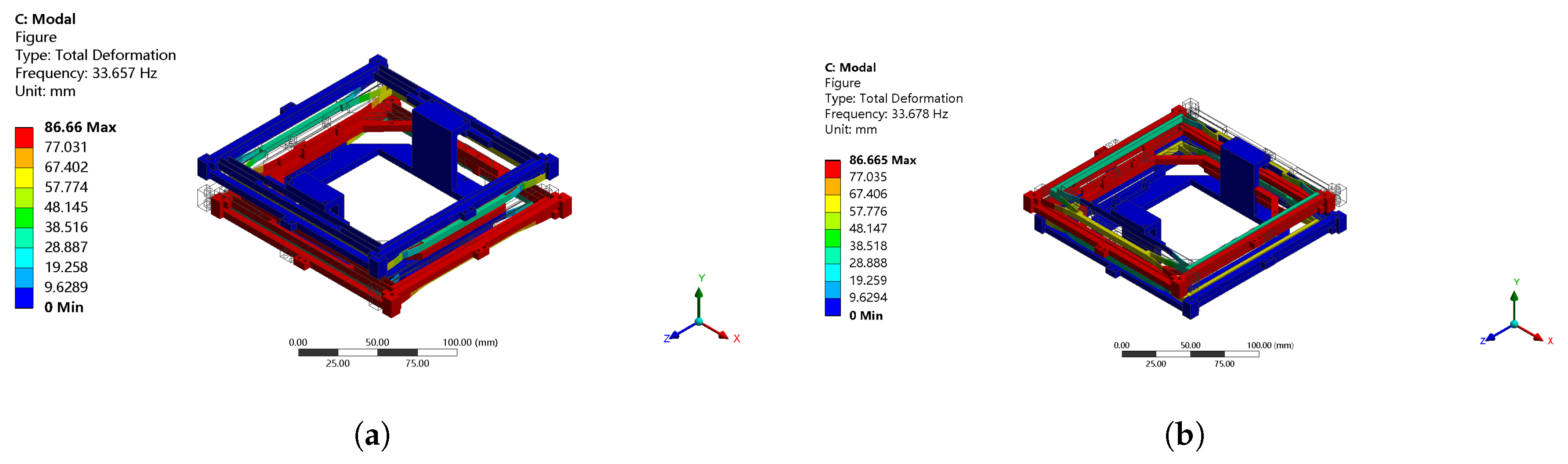
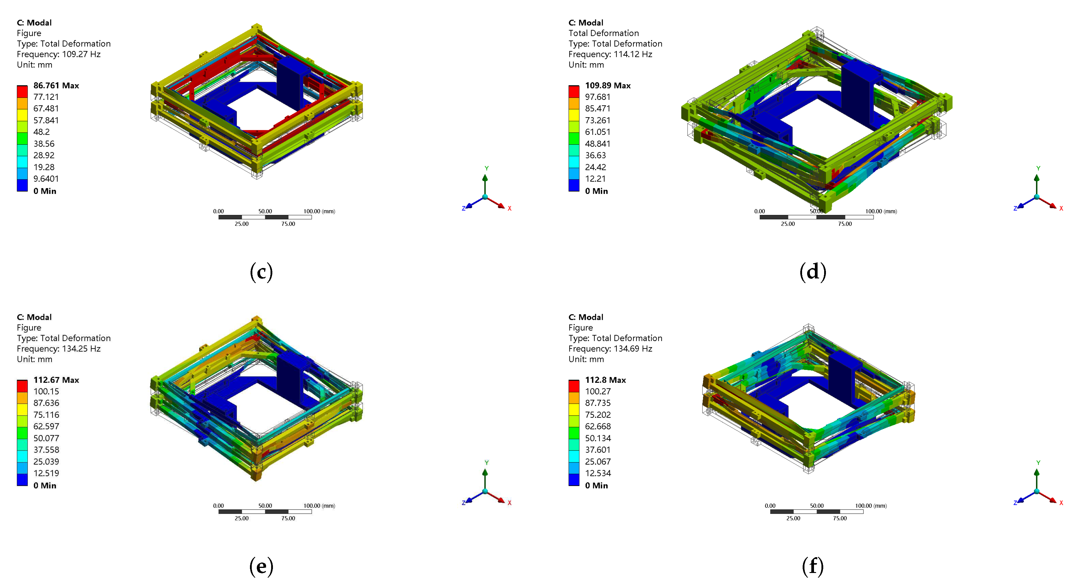
Section 3, respectively. The simulation study is described in Section 4; the simulation evaluation revealed the promising performance of the designed xy stage and also verified the analytical model. The difference between those results was analyzed in detail. Moreover, a comparison study with the previous designs was carried out and is described in Section 5. Finally, Section 6 concludes this paper.

2. Mechanism Design

Mechanism design of the proposed xy stage is presented in this section. The designed xy stage is constructed by four basic structures, two groups of fixtures, a platform, and a base. In this work, the stage mechanical design and decoupling mechanical design have the same structure (i.e., basic structure), which offers convenience for manufacturing. The symmetrical structure also provides benefits on stable and compact design. The details of the structure are presented in the following.

2.1. Basic Structure and Fixture

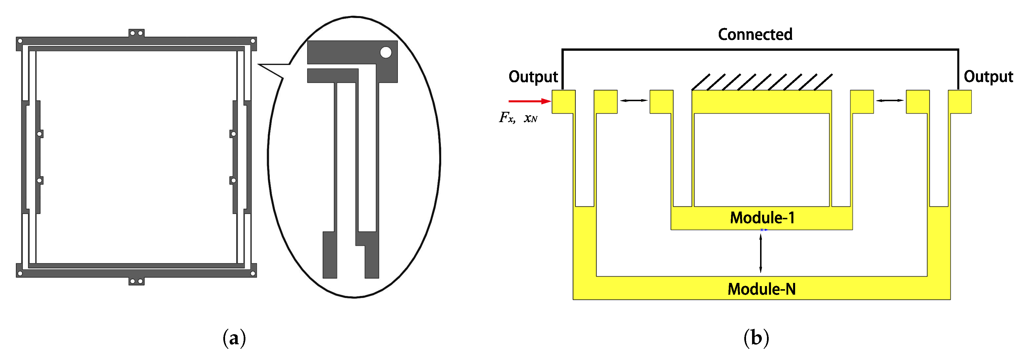
The basic structure is shown in Figure 1a. This structure provides a large stroke by employing multistage compound parallelogram flexures (MCPF) [11]. As an improved design of the compound parallelogram flexures (CPFs), the MCPF has a large range of motion, according to previous research. MCPF meets the requirement of compactness and adapts to practical manufacturing. The range of motion of the MCPF depends on the ranges of motion of the basic modules (CPF) and the number N of basic modules, as shown in Figure 1b.
The basic structure in Figure 1a has two MCPFs with 1.5 basic modules. Differently from the intuitive structure of MCPF, those two MCPFs were designed to tackle the following three issues.
(a) To make a large output platform, the MCPFs are extended horizontally. In this way, the size of the platform can reach up to 100 × 100 mm2.
(b) The module number N of the MCPF is not an integer. This design involves half of CPF, which can reverse the direction of output motion. In this design, reversing the output motion direction improves the compactness effectively. Here, 1.5 basic modules provide enough motion, as the range of motion also depends on CPF. The ranges of motion of CPFs can be improved by using narrower and longer leaf flexures, as there is still enough space for them. The parameters of this part will be presented in the simulation study later. All of the motions are realized by leaf flexures of basic structures and all basic structures are of the same design.
(c) These two MCPFs are connected with each other by leaf flexures of secondary modules, which are designed to overcome the undesirable bending flexures. Once fixing the output end of the basic structure, it provides a force along the y-axis. The secondary module of leaf flexures on the top bends inward, and the secondary module leaf flexures on the bottom will bend outward. It is easy to find that the directions of bending tendency of the two MCPFs are always contrary. Hence, the connection can overcome the undesirable bent flexures and ensure a translational displacement.
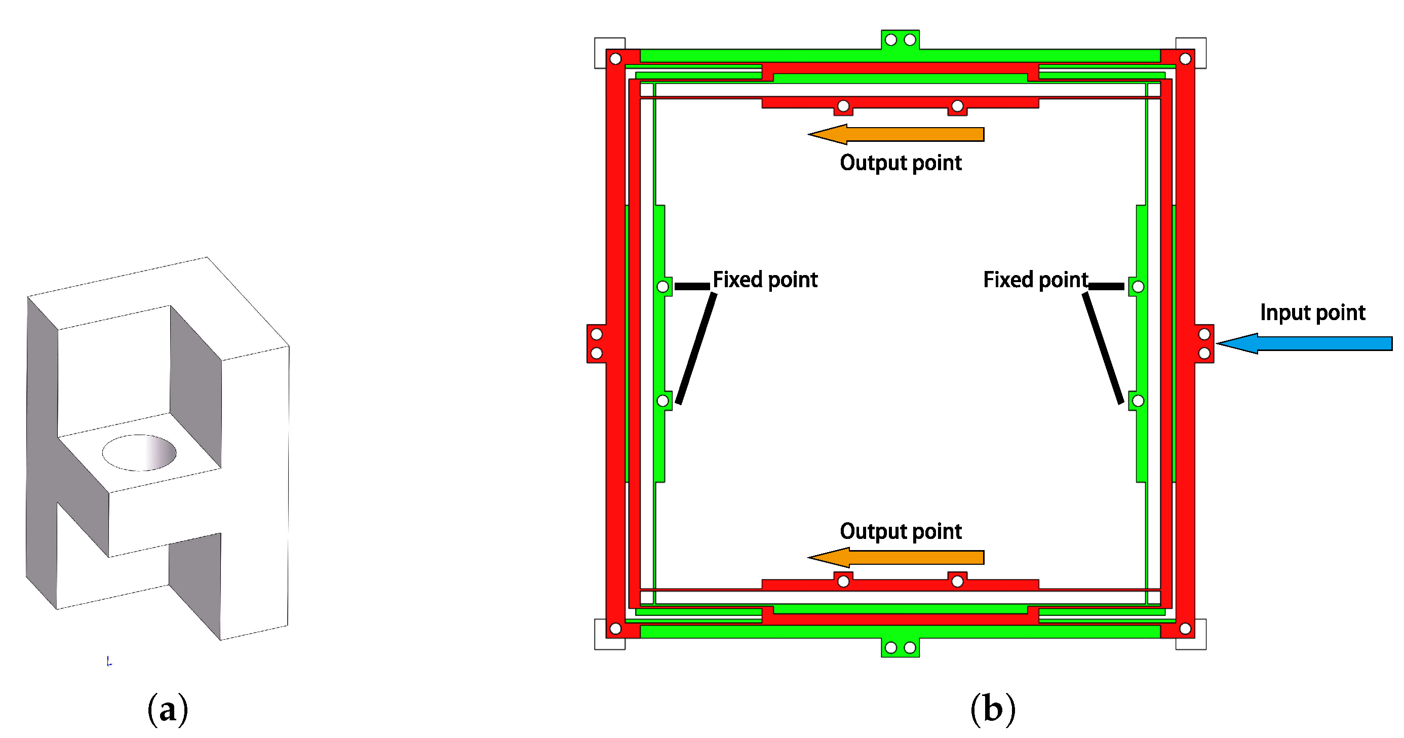
When a torque is exerted to the basic structure, it also causes undesirable bent flexures. To tackle this issue, fixtures and a novel assembly method are used. As per previous research on xy stages, the structures can eliminate the torque by introducing a square-shaped frame. In this design, the square frame is combined with two basic structures and fixtures. The fixture is shown in Figure 2a. The special structure of the fixtures locks the two basic structures, which has favorable effect on eliminating the torque. In this design, there are four layers of basic structures. Using the beams of MCPFs to constitute frames for leaf flexures reduces the weight of the whole design dramatically, as compared with that using frames directly. In this way, the assembled stroke structure for one axis is shown in Figure 2b.

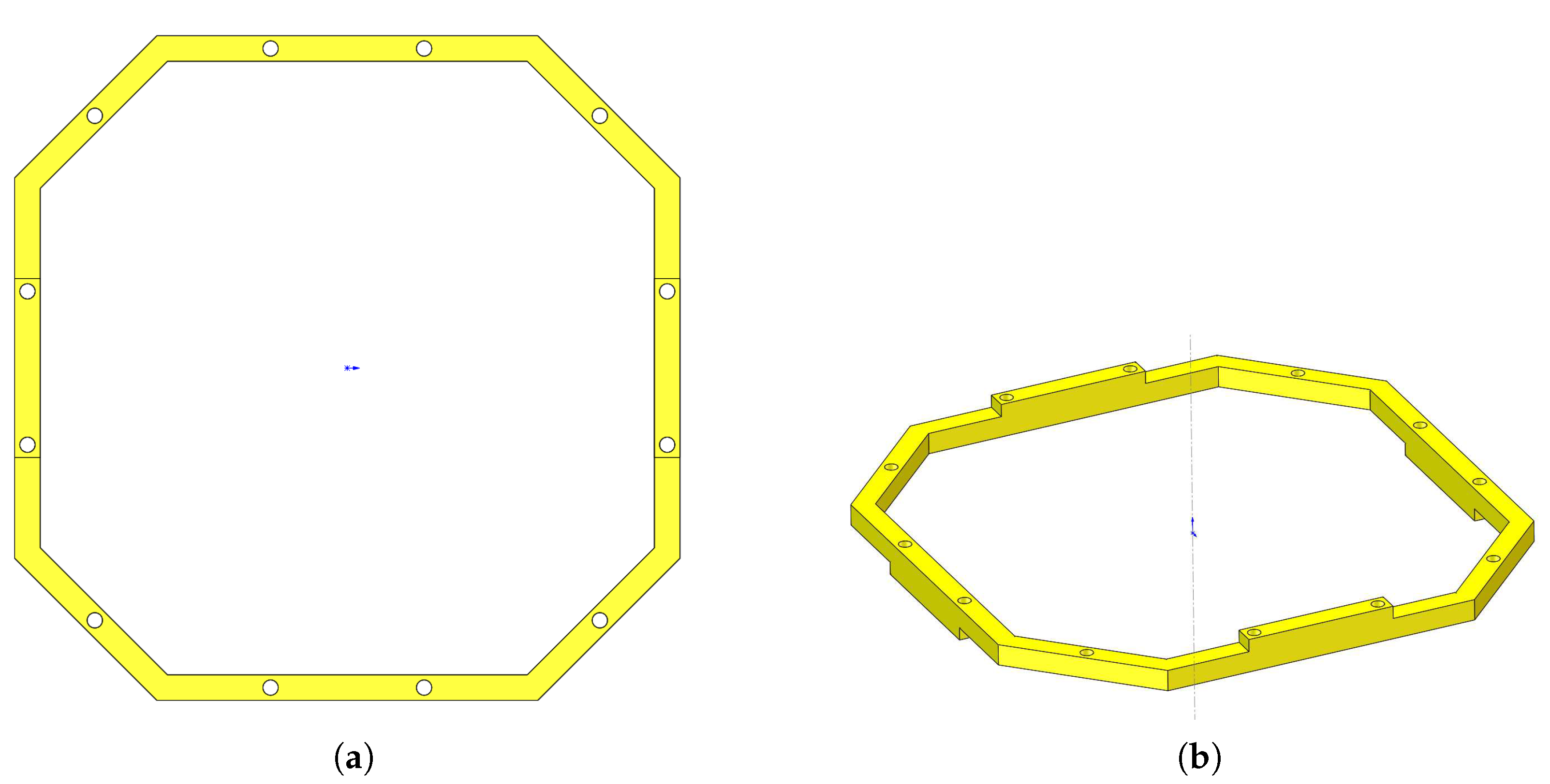
2.2. Platform and Base

The output platform is designed as a large hollow stage, which adapts for experimental use under a microscope, including cell microinjection and material micromanipulation. The platform is the output end of this design. It has 12 fixing points; four points are used for the experimental stage, four for the x-axis stroke structure, and four for the y-axis stroke structure, as shown in Figure 3. The gaskets over fixing points of the platform bond the x and y-axis stroke structures directly. The motions of these two stroke structures are transmitted to the output platform, and the pure motions on x-axis and y-axis are compounded by the platform.
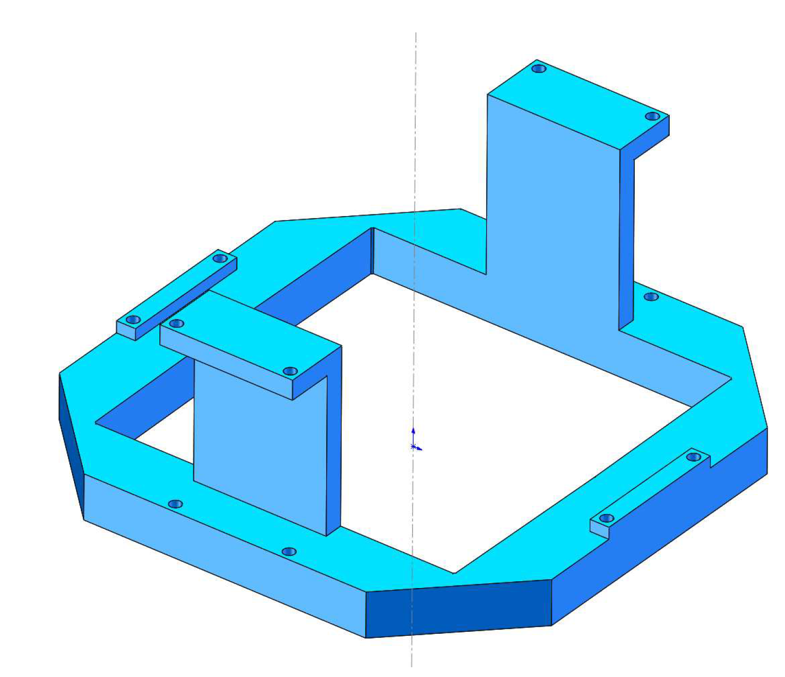
The base design is shown in Figure 4. There are four fixing points to mount the design on the experimental bench. Like the platform, the base has gaskets to bond with x and y-axis stroke structures.
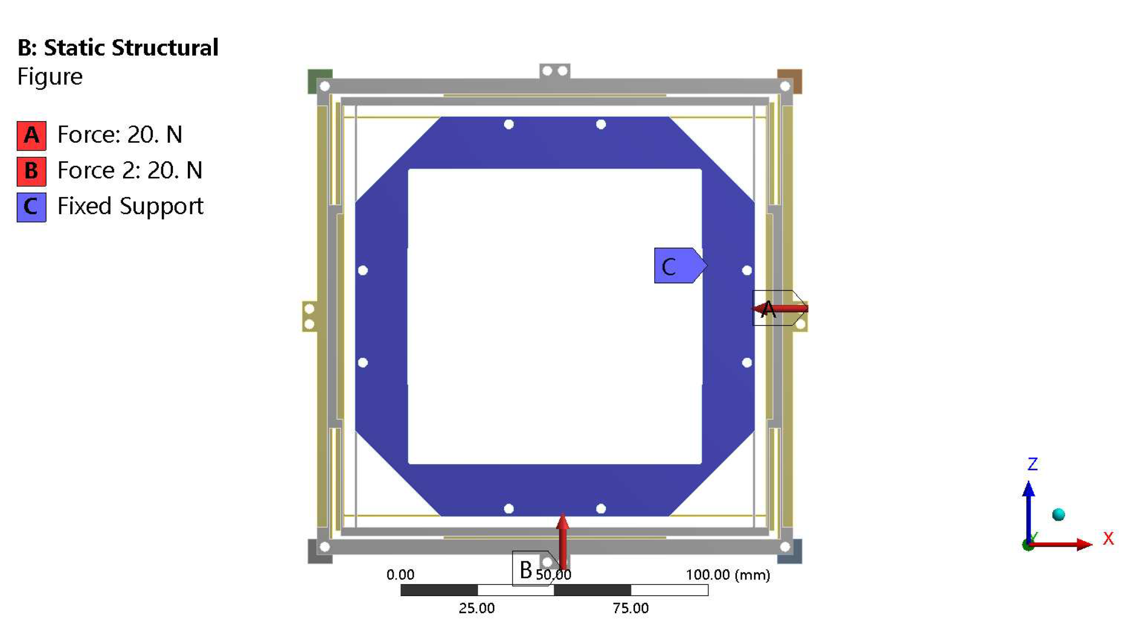
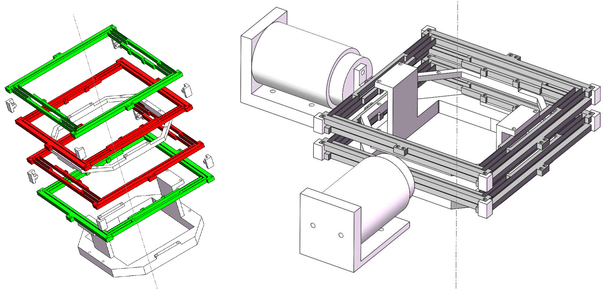
2.3. Stage Assembly

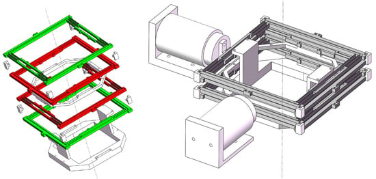
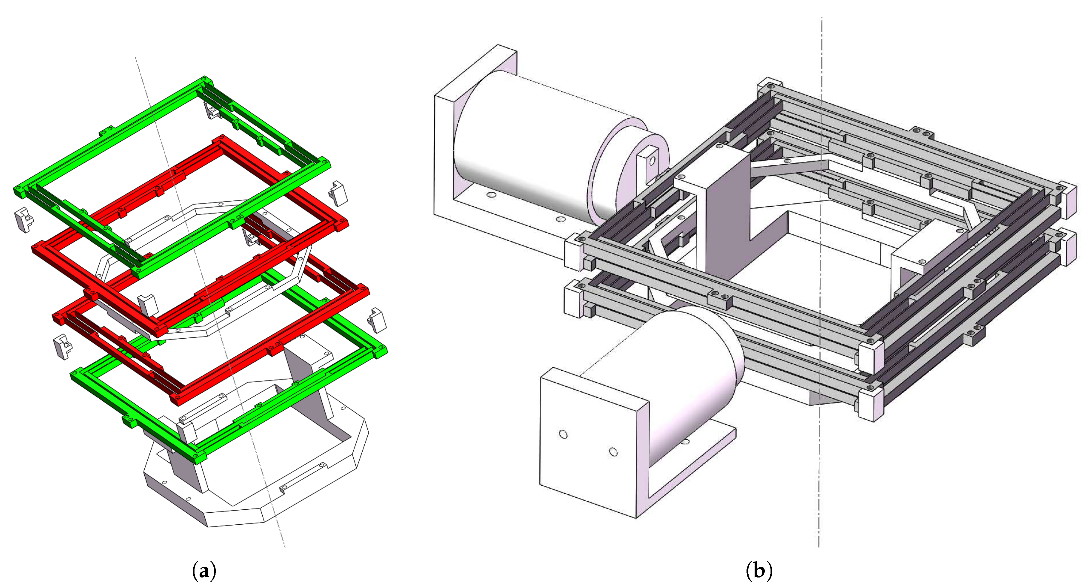
The assembled stage is shown in Figure 5. The base is the frame for the whole design, which provides support to other structures. The stroke structure at the bottom is responsible for the motion on the x-axis, while the stroke structure at the top is for the motion on the y-axis. The platform is fixed between the two stroke structures. To present the operating principle of the stage, the four layers of basic structures are numbered from bottom to top as 1st, 2nd, 3rd, and 4th layer, respectively. From the rule of these serial layers, the 1st and 2nd layers constitute the x-axis stroke structure, while the 3rd and 4th layers constitute the y-axis stroke structure. The 1st and 4th layers are connected with the base directly, so are called stroke mechanical designs. These two layers provide the strokes relative to the static base. Then, the strokes are transmitted to the decoupling mechanical designs, i.e., the 2nd and 3rd layers, by the group of fixtures. The decoupling mechanical designs are connected to the platform, and the final motion output is given by the platform. As shown in Figure 2b, when defining the red layer as the decoupling mechanical design and the green layer as the stroke mechanical design, the operating principle is clear to observe. The fixed points connect the static base, the input point connects the VCM, and the output points connect the platform; refer to Figure 5a.
As shown in Figure 5b, the linear strokes are provided by two VCMs connecting to the decoupling mechanical design, whose directions are orthometric to the motion direction of the MCPFs on the 2nd and 3rd layers. As presented earlier, the beams of the two layers can be treated as a square frame. The linear stroke on the decoupling mechanical design will be received by the stroke mechanical design. In this way, the VCMs do not suffer from transverse displacement.
The mechanical design and operating principles have been presented in this section, and analytical modeling is introduced in the following section.

3. Analytical Modeling

In this section, analytical modeling of the xy micropositioning stage is presented. According to the description in mechanism design, there is only one structure, i.e., the basic structure, which is used to realize the function of the stage. As the basic structure is constituted by MCPFs and MCPFs generate large elastic deformation through the leaf flexures, the modeling is most relevant to the leaf flexure [11].
In previous research, the force–displacement relationship of MCPF has been given; it must be presented in this section for the mechanism design. After considering the boundary conditions of the deformation, the stiffness of MCPF can be determined as
K N = F x x N = E b h 3 N l 3
where l and b denote the length and width of the leaf flexure, while h and E are the thickness and Young’s modulus of the material, respectively.
As the total deformation of output platform on each axis is uniformly distributed on each flexure hinge of the MCPF, the deformation of each hinge is relatively small. Therefore, the nonlinear stiffness of MCPF under large deformation is ignored in this paper. Actually, if each flexure hinge undergoes large deformation, the equation of equivalent stiffness Equation (1) does not hold, as the stiffness is nonlinear. The nonlinear stiffness modeling is beyond the scope of this work.
From Equation (1), the maximum translation of one-sided design is calculated further as
x N m a x = F x m a x K N = N σ y l 2 3 E h
where σ y is the yield stress of the material. From Equation (2), x N m a x is positively related to l and N, and negatively related to h. That means that a larger length and smaller width of the leaf flexure provide larger stroke. In practical applications, the parameters l and h are limited by the manufacturing tolerance, while N is limited by the compactness requirement. As N increases, the size and weight of the stage will increase dramatically, because the beam of the additional CPF becomes longer. x N m a x also depends on the space between different modules in one MCPF, which is not expressed in Equation (2) directly.
In this design, the module number of MCPF was chosen as N = 1.5 for illustration. Thus, the sum of two-sided maximum translation is
d m a x = 2 x 1.5 m a x = σ y l 2 E h
Considering safety and a practical situation, the assigned maximum translation D m a x should be less than d m a x . After confirming the range of the assigned translation, the maximum driving force F m a x to generate the motion can be calculated accordingly.
The stiffness of the basic structure should be determined. As the structure is constituted by two MCPFs, the stiffness of the basic structure is 2 K 1.5 . According to the section of mechanism design, on one axis (x or y-axis), there is one stroke mechanical design for this axis and decoupling mechanical design for the other axis. The conditions are enough to determine the stiffness of the stage on one axis as follows.
K = 8 E b h 3 3 l 3
The maximum driving force occurs on one-sided maximum translation, which is half of D m a x . Considering Equation (2), F m a x is calculated by
F m a x = 1 2 D m a x K = 4 E b h 3 D m a x 3 l 3
In this design, to provide enough driving force, the VCMs are selected to provide larger maximum force than F m a x .
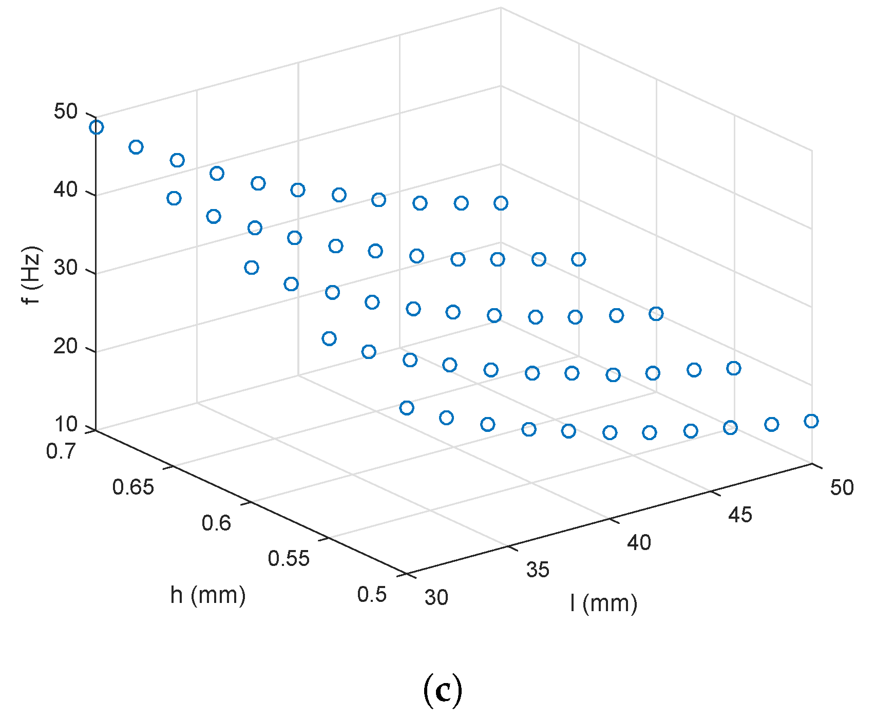
For the three most important parameters in this study, which are the maximum translation on one side (x), safety factor (s), and resonant frequency (f), the equations are derived in the following.
Considering Equations (1) and (4), the equation of maximum translation on one side should be presented as
x = K F = 3 l 3 F 8 E b h 3
For the safety factor, considering Equations (1) and (2), F x m a x satisfies the equation
F x m a x = σ y b h 3 3 l
which proves that F σ in this structure. The equation of s is as follows.
s = σ y σ = F x m a x F
Define d x and d y as the deformations on two axes, respectively. Considering the motion decoupling of mechanical design, the mechanical system can be simplified as a two-dimensional mass-spring system. Thus, the free motion equation (in the absence of external forces) is shown as follows:
m 0 0 m d 2 d x d t 2 d 2 d y d t 2 + K 0 0 K d x d y = 0 0
where K can be calculated by Equation (4), and m is the equivalent mass of the moving block for the stage. Then, the resonant frequency has the relationship with the parameters given below.
f = 1 2 π K m
Equations (6), (8), and (10) will be used to calculate the analytical results of the design for comparison study with the simulation results in the next section.

4. Simulation Study

The case study design of the structure parameters and a finite-element simulation study with ANSYS software are described in this section, which verify the performance of the designed stage.
Several parameters of the xy stage have been presented in analytical modeling, which is not sufficient to obtain an accurate result. The stage has four layers with a complex structure. and different factors are involved which influence the result. The ANSYS Workbench provides a solid model with a fine mesh instead of a traditional mathematical model [17]. By defining the solid model, objectives, and constraints, a more accurate result can be obtained.

4.1. Design Variables

In this study, the leaf flexures of the basic structure were the only objectives, as the elastic deformations only occur on them. Other structures (fixture, platform, and base) were approximately treated as rigid bodies, whose stiffnesses are much larger than those of the leaf flexures. From Equations (6), (8), and (10), the performance mainly depends on parameters h, l, b, and the material of the leaf flexures. The material of the basic structure was chosen to be Al-7075, i.e., a popular flexible material, whose mechanical properties are listed in Table 1. Considering the compactness requirement of the design, b was set as 5 mm, which is almost the minimum value to ensure a high stiffnesses of the beams on the basic structures. In this way, the parameters of the leaf flexures that can be used for the case study include l and h.
As a result, the design objectives of the xy stage were to tune two design variables under constraints. To enhance the performance and compactness of the stage, there were three objectives as follows.
T o t a l D e f o r m a t i o n : M a x i m u m ( 2 x ) S a f e t y F a c t o r : M i n i m u m ( s ) R e s o n a n t F r e q u e n c y ( f )
The relationship of the variables can be summarized below.
X Y S t a g e ( x , s , f ) = f ( l , h )

4.2. Setup and Result of Case Study

The parameter setup is shown in the following, which are the conditions of a case design with better performance.
2 x 5 mm s 1 M a x i m i z e f 30 mm l 50 mm 0.5 mm h 0.7 mm
The conditions were selected due to the following reasons. In this study, the objectives were to design a large-range-of-motion xy stage with a large platform. Thus, x had to be guaranteed. By setting the maximum translation of the whole stage to be greater than or equal to 5 mm, the range of motion of the stage could reach up to ±3.54 mm. The safety factor s was set by taking into account the compactness requirement. As an overly high s induces structure redundancy, the initial parameter of s was not set too high. To avoid over-constraints which cause no solution, no upper limitation for s was set in Equations (13). In this way, the possible minimum value of s in the case study result was adopted in this study. Another noteworthy parameter is h.
The relationships of thickness and length of the leaf flexure with x, sm and f are shown in Figure 6. It indicates that x increases with the increase in l and decrease in h. At the same time, s and f decrease. The change law and tendency are consistent with those of the analytical model results.
The result of the best case is indicated by l = 32 mm and h = 0.6 mm, which is the point that well satisfies the conditions in Equations (13).

4.3. Simulation Results

The simulation results were obtained by ANSYS Workbench software. The same setup was used for the case study. The setup is shown in Figure 7, which reveals three analysis settings. Considering the presentation in mechanism design, the force A simulated the actuator along x-axis, while the force B simulated the actuator on the y-axis. The forces acted on the decoupling mechanical designs of x and y-axes, respectively. The fixing support was applied on the base.
That way, the simulation diagrams of the total deformation on x-axis, safety factor, and resonant frequency are shown in Figure 8a,b and Figure 9, respectively. The operating principles of the stroke mechanical designs and decoupling mechanical designs are clearly illustrated in Figure 8a,c,d, which indicate that the objectives of large stroke and motion decoupling were attained, as there was almost no undesired deformation.
In addition, the setup in Figure 8c,d employs the force A and the fixing support, which is the same setup as that in Figure 7. The result in Figure 8c shows that the influence (of employing the force B on y-axis) was less than 0.001 mm on the x-axis deformation. The result in Figure 8d shows that the actuator on one axis causes undesired deformation of less than 0.062 mm on the z-axis, which is far less than the deformation on the desired axis, i.e., 3.4877 mm. The largest deformation appeared on the platform, which was the resultant deformation of all the deformations on x and y-axes. The simulation results confirm the fine motion decoupling property of the xy stage.
Figure 8b shows that the safety factor is large, which is especially steady on the leaf flexure. The parameters are given in Table 2. In addition, to provide appropriate force for the deformation, the actuators should be selected carefully. As a result, an xy micropositioning stage with a large hollow platform can be produced. The compactness and range of motion can be ensured by the parameters, as shown in the simulation result in Table 2.
The comparison of the results from the analytical model and simulation study is shown as follows. Considering Equation (6), if the driving forces are set to 20 N, the maximum translation on one side is 3.1746 mm. This result is approximate to the deformation result of simulation study, i.e., 3.5437 mm. As the calculation process treated the beams on basic structures as rigid bodies, the analytical model result was slightly smaller than the simulation result.
Under the same settings with the calculation process of the maximum translation, the calculation result of the safety factor was 3.9297, which was obtained by Equation (8). The discrepancy may have been caused by the larger deformation in the process of simulation.
As the volume of the moving block was 49.22 cm3, the mass m can be calculated by combining the density shown in Table 1, which gives the value of 0.2416 kg. In this way, the analytical model result of resonant frequency was 33.9735 Hz, which approximates to the 1st and 2nd modes of resonant frequency of the simulation result. It indicates that the resonant frequency can be easily predicted by the analytical model, even with extra load added. Moreover, as shown in Figure 9, the moving directions of the 1st and 2nd modes of resonant frequency in the simulation result are consistent with the two available moving dimensions of the proposed stage, and the value of the 3rd mode of resonant frequency is over three times the 1st and 2nd modes of resonant frequency. It indicates that the proposed stage exhibits a stable motion performance.

5. Comparison Study

The comparison among the performances of this design and previous designs using VCM drives is shown in Table 3. Differently from the previous studies, the proposed design has a hollow platform, which provides convenience to pass light though samples on the platform. Therefore, it is more suitable to be used along with a microscope. Meanwhile, the larger size caused by the hollow platform is acceptable since there is a 95 × 95 mm2 hollow area. Moreover, as compared with the previous work, the range of motion on one axis is smaller and the resonant frequency is larger. Since the maximum actuation force of this work is much lower and the minimum safety factor is much larger than the required values, it can further improve the range of motion at the cost of increasing the maximum actuation force and decreasing the minimum safety factor if a larger range of motion is required.

6. Conclusions

An xy flexure micropositioning stage with a large hollow platform has been presented in this work, which has a parallel-kinematic structure and is actuated by two VCMs. The proposed stage has four layers of structure, which greatly reduces the dimensions on the xy plane. By separating the stroke mechanical design and decoupling mechanical design, it provides convenience for further experimental study and potential commercial use. The simulation result showed that the hollow of the platform reaches up to 95 × 95 mm2 and the range of motion reaches up to 7.0873 × 7.0873 mm2. The large hollow platform, large range of motion, and compact structure of the design ensure that it can be used directly in practical applications with a microscope. Moreover, the novel structure, which takes full advantage of MCPF beams, is able to reduce the weight, increase the frequency, and save space for the design effectively. Considering Table 3, the range of motion can be further improved, as the maximum actuation force is obviously smaller than in previous designs. This design has advantages on integrated performance of compactness, decoupling, range of motion, safety factor, and natural frequency as compared with previous designs. In the future work, an experimental study of the xy stage will be produced. This design which has better performance and is better at adapting to practical manufacturing will be confirmed by optimization, and the parameters of the design will be verified by experiments in practice.

Author Contributions

H.Z. and Z.W. performed the literature view and mechanism design; H.Z. and Z.W. conducted the analytical modeling and simulation study; H.Z., Z.W., and Q.X. wrote the paper. All authors have read and agree to the published version of the manuscript.

Funding

This work was supported in part by The Science and Technology Development Fund, Macau SAR (file numbers 179/2017/A3, 0022/2019/AKP, 0153/2019/A3, and 0008/2020/A), and the University of Macau (file numbers MYRG2018-00034-FST and MYRG2019-00133-FST).

Conflicts of Interest

The authors declare no conflict of interest. The founding sponsors had no role in the design of the study; in the collection, analyses, or interpretation of data; in the writing of the manuscript, or in the decision to publish the results.

References

  1. Wang, P.; Xu, Q. Design of a flexure-based XY precision positioning stage with constant force output. In Proceedings of the IECON 2016-42nd Annual Conference of the IEEE Industrial Electronics Society, Florence, Italy, 23–26 October 2016; pp. 524–529. [Google Scholar]
  2. Wang, F.; Shi, B.; Tian, Y.; Huo, Z.; Zhao, X.; Zhang, D. Design of a novel dual-axis micromanipulator with an asymmetric compliant structure. IEEE ASME Trans. Mechatroni. 2019, 24, 656–665. [Google Scholar] [CrossRef]
  3. Yang, X.; Zhu, W.L. Design, Analysis and Control of a XY Parallel Nanomanipulator with Multiple Actuation Modes. IEEE Trans. Ind. Electron. 2019, 67, 7639–7648. [Google Scholar] [CrossRef]
  4. Khan, M.U.; Prelle, C.; Lamarque, F.; Büttgenbach, S. Design and assessment of a micropositioning system driven by electromagnetic actuators. IEEE ASME Trans. Mechatron. 2016, 22, 551–560. [Google Scholar] [CrossRef]
  5. Deng, J.; Liu, Y.; Li, K.; Zhang, S. Design, Modeling and Experimental Evaluation of a Compact Piezoelectric XY Platform for Large Travel Range. IEEE Trans. Ultrason. Ferroelectr. Freq. Control. 2019, 67, 863–872. [Google Scholar] [CrossRef]
  6. Sun, X.; Chen, W.; Zhou, R.; Zhang, J.; Chen, W. Design and analysis of a new flexure-based XY micropositioning stage with decoupled motion characteristic. In Proceedings of the IEEE International Conference on Robotics and Biomimetics (ROBIO), Guangzhou, China, 11–14 December 2012; pp. 1011–1016. [Google Scholar]
  7. Liu, X.R.; Huang, W.Q.; Wang, Y. A novel 2D piezo-nanopositioning stage based on triangle amplifier mechanism. In Proceedings of the 2016 Symposium on Piezoelectricity, Acoustic Waves, and Device Applications (SPAWDA), Xi’an, China, 21–24 October 2016; pp. 314–318. [Google Scholar]
  8. Lee, J.W.; Li, Y.C.; Chen, K.S.; Liu, Y.H. Design and control of a cascaded piezoelectric actuated two-degrees-of-freedom positioning compliant stage. Precis. Eng. 2016, 45, 374–386. [Google Scholar] [CrossRef]
  9. Pinskier, J.; Shirinzadeh, B.; Clark, L.; Qin, Y.; Fatikow, S. Design, development and analysis of a haptic-enabled modular flexure-based manipulator. Mechatronics 2016, 40, 156–166. [Google Scholar] [CrossRef]
  10. Xue, G.; Toda, M.; Ono, T. Comb-drive XYZ-microstage based on assembling technology for low temperature measurement systems. In Proceedings of the 2015 International Conference on Electronics Packaging and iMAPS All Asia Conference (ICEP-IAAC), Kyoto, Japan, 14–17 April 2015; pp. 83–88. [Google Scholar]
  11. Xu, Q. Design and development of a compact flexure-based XY precision positioning system with centimeter range. IEEE Trans. Ind. Electron. 2013, 61, 893–903. [Google Scholar] [CrossRef]
  12. Wan, S.; Xu, Q. Design and analysis of a new compliant XY micropositioning stage based on Roberts mechanism. Mech. Mach. Theory 2016, 95, 125–139. [Google Scholar] [CrossRef]
  13. Li, Y.; Xu, Q. A totally decoupled piezo-driven XYZ flexure parallel micropositioning stage for micro/nanomanipulation. IEEE Trans. Autom. Sci. Eng. 2010, 8, 265–279. [Google Scholar] [CrossRef]
  14. Zhang, X.; Xu, Q. Design of a new decoupled compliant XYZ parallel-kinematic nanopositioning stage. In Proceedings of the IEEE Region 10 Conference (TENCON 2015), Macao, China, 1–4 November 2015; pp. 1–4. [Google Scholar]
  15. Liu, H.; Fan, S.; Xie, X.; Zhang, Z.; Fan, D. Design and modeling of a novel monolithic parallel XY stage with centimeters travel range. Adv. Mech. Eng. 2017, 9, 1687814017729624. [Google Scholar] [CrossRef]
  16. Xu, Q. New flexure parallel-kinematic micropositioning system with large workspace. IEEE Trans. Robot. 2011, 28, 478–491. [Google Scholar] [CrossRef]
  17. Wu, Z.; Xu, Q. Design, optimization and testing of a compact XY parallel nanopositioning stage with stacked structure. Mech. Mach. Theory 2018, 126, 171–188. [Google Scholar] [CrossRef]
  18. Lin, R.; Li, Y.; Zhang, Y.; Wang, T.; Wang, Z.; Song, Z.; Dou, Z.; Qian, J. Design of A flexure-based mixed-kinematic XY high-precision positioning platform with large range. Mech. Mach. Theory 2019, 142, 103609. [Google Scholar] [CrossRef]
  19. Zhang, Z.; Liu, B.; Wang, P.; Yan, P. Design of an additive manufactured XY compliant manipulator with spatial redundant constraints. In Proceedings of the 35th Chinese Control Conference (CCC), Chengdu, China, 27–29 July 2016; pp. 9149–9154. [Google Scholar]
  20. Wang, N.; Liang, X.; Zhang, X. Design and analysis of a novel XY micro-positioning stage used corrugated flexure beams. In Proceedings of the International Conference on Intelligent Robotics and Applications, Guangzhou, China, 17–20 December 2014; Springer: Cham, Switzerland, 2014; pp. 586–595. [Google Scholar]
Figure 1. Illustrations of (a) basic structure and (b) multistage compound parallelogram flexure (MCPF) with N modules.
Actuators 09 00065 g001
Figure 2. Illustrations of (a) fixture and (b) assembled stroke structure (top view).
Actuators 09 00065 g002
Figure 3. Illustrations of (a) top view and (b) overview of the platform.
Actuators 09 00065 g003
Figure 4. CAD model of the base.
Actuators 09 00065 g004
Figure 5. Illustrations of (a) explosive view and (b) CAD model of the assembled xy stage.
Actuators 09 00065 g005
Figure 6. The relationships of thickness and length of the leaf flexure with (a) total deformation, (b) safty factor, and (c) resonant frequency.
Actuators 09 00065 g006aActuators 09 00065 g006b
Figure 7. Analysis settings of finite-element simulation study.
Actuators 09 00065 g007
Figure 8. Finite-element simulation results. (a) Total deformation on x-axis, (b) safety factor, (c) result of motion decoupling, and (d) result of undesired deformation.
Actuators 09 00065 g008
Figure 9. (a) 1st, (b) 2nd, (c) 3rd, (d) 4th, (e) 5th, and (f) 6th modes of resonant frequencies obtained by finite-element simulation.
Actuators 09 00065 g009aActuators 09 00065 g009b
Table 1. Mechanical properties of Al-7075 material.
PropertyValue
Density2810 kg m−3
Young’s Modulus71.7 GPa
Poisson’s Ratio0.33
Bulk Modulus70.29 GPa
Shear Modulus26.96 GPa
Tensile Yield Strength503 MPa
Compressive Yield Strength503 MPa
Tensile Ultimate Strength572 MPa
Table 2. Simulation result of performance for the xy stage.
ParameterValue
Dimension of the stage158 × 158 × 56.5 mm3
Dimension of the platform100 × 100 mm2
Motion range on one axis±3.5437 mm
Safety factor minimum3.0993
Resonant frequency33.657 Hz
Table 3. Performance comparison versus the previous xy stages with voice coil motor (VCM) driving.
Proposed StageXu [11]Liu et al. [15]
Dimension158 × 158 mm2120 × 120 mm2133 × 133 mm2
PlatformHollow (95 × 95 mm2)SolidSolid
Maximum actuation force on one axis20 N117 N90 N
Motion range on one axis7.0873 mm11.7050 mm20 mm
Minimum safety factor3.00062.21.25
Resonant frequency36.518 Hz29.45 Hz34.385 Hz

