1. Introduction
With the continuous implementation of energy-saving and emission reduction policies, hybrid electric vehicles and pure electric vehicles are gradually replacing traditional internal combustion engine (ICE) vehicles. Automatic mechanical transmission (AMT) based novel structures have drawn rising attention from hybrid and electric vehicle manufacturers [
1,
2]. An AMT equipped with a shift assist mechanism can enhance the shift quality and the fuel consumption of the traditional AMT by properly coordinating the friction clutch and the motor connected to the output shaft [
3]. The auxiliary shifting mechanism added to AMT changed the shifting process in a way that is different compared to the traditional ones, and its performance still needs to be further validated.
The vehicle usually operates under elaborate and varying conditions. Waving roads are a common driving condition, especially in mountainous regions [
4]. The main disadvantage of the traditional AMT is the torque interruption [
5]. The increase of the road grade is always accompanied by surging resistant torque, which deteriorates the transmission’s shifting performance.
Over the last decade, researchers throughout the world have attempted to improve the transmission shift performance and fuel saving. The approaches are generally classified into two different types [
6]: (a) increasing the gear step number in current transmission layouts, such as 9-speed automatic transmission (AT) and 10-speed AT and (b) inventing or developing novel transmission architecture, such as the dual-clutch transmission (DCT) or AMT with a torque gap filler (TGF). The TGF indicates the device or the mechanism planted on the AMT architecture that provides additional power routes in the shifting process. Various TGFs have been proposed, such as planting an epicyclic mechanism transmitting the engine torque to the AMT secondary shaft [
7] and utilizing a flywheel to store the engine power for torque compensation as demonstrated in [
8]. Replacing the synchronizer of the fifth gear by a friction clutch, namely assistant clutch (ACL), allows the engine torque to be transmitted through the secondary shaft to the output shaft [
9]. However, the application of the foregoing TGFs are normally restricted by conditions such as allowable thermal loads or the torque gap filling performance.
AMT integrated with an electric motor, or a hybridized AMT (HAMT), is a new alternative for torque gap filling [
10]. The new architecture preserves the advantage of high efficiency, high torque capacity, and simple structure of AMT, and it also improves riding comfort. Nevertheless, in the shifting process of MT and AMT, the clutch is required to be entirely disengaged to minimize the friction load on synchronizers, which aims to boost the engagement and disengagement of gears. While the electric motor works to fill the torque gap, the gear engagement demands higher friction torque from synchronizers, which will cause extra abrasive wear on them.
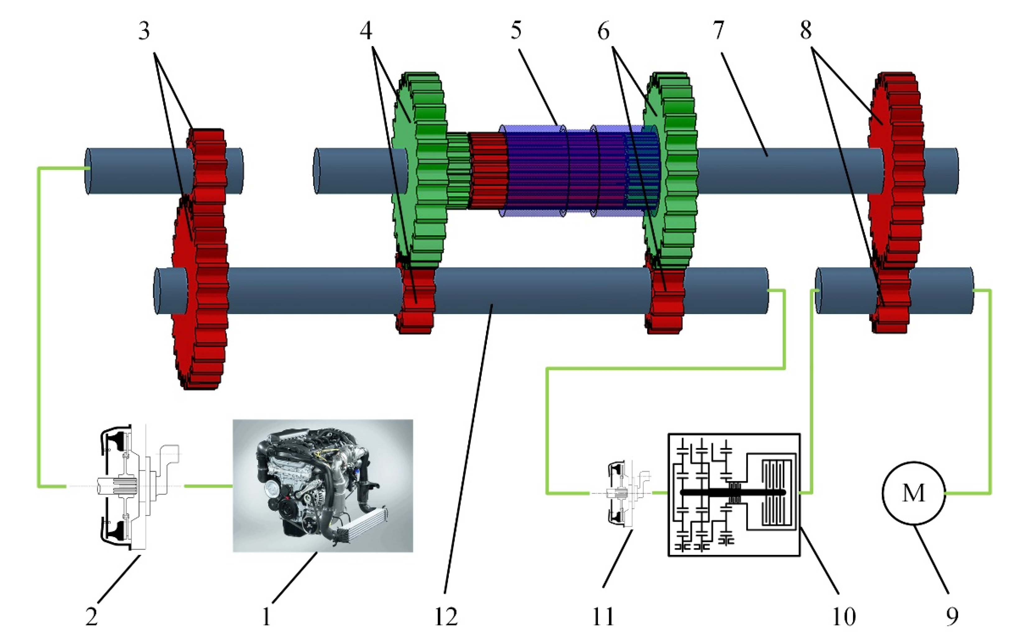
The gearshift assist mechanism is designed as an auxiliary shifting device concept for traditional AMT to fix the above issues. In the shifting process, the torque of an electric motor will be utilized to compensate for the torque interruption, which alleviates the surging resistant torque. Simultaneously, a synchronizing clutch will be engaged to synchronize the preshift gear and the transmission output shaft. The synchronizing clutch is a substitute for the synchronizers and the clutch of AMT in the shifting process (as shown in
Figure 1). Yet, the structure of the gearshift assistant mechanism inevitably leads to mutual coupling between the motor torque and the clutch friction torque. In addition, the friction coefficient of the relatively rubbing dry clutch pads varies depending on the working speed, temperature, and surface worn condition. The uncertainty of the friction torque also degenerates the torque filling performance. In general, the key to a steady auxiliary shifting performance hinges on the proper dynamic coordination of the motor torque and the clutch friction torque with respect to the perturbations of the road grade and of the friction coefficient.
However, only by applying the feedforward decoupling controller and the disturbance compensation controller cannot guarantee that the friction torque and the motor torque would have an ideal target tracking performance against the parameter perturbations. Proportional-integral-differential (PID) controllers are widely utilized in the industry, owing to their simplicity and satisfactory efficiency. With the development of the computer, the massive tuning work could be automatically done by proper programming. Applying PID controllers for feedback adjustment can effectively improve the robustness of the target tracking performance of the system outputs, and the key to the implementation of the PID controllers in the transmission is their tuning of the parameters.
In the upshifting process of AMT with a gearshift assistant mechanism, the vehicle is powered by both the friction torque and the motor torque, and the shifting performance is evaluated by the reference tracking performance of the clutch speed differences and the output acceleration. In other words, AMT with a gearshift assistant mechanism is considered as a two-input and two-output (TITO) system, and the self-tuning method of PID parameters for the foregoing TITO system is an essential point for the controller’s implementations [
11]. Unlike the single-input/single-output (SISO) system, the TITO system is more sophisticated to be properly controlled. Generally, the TITO system cannot be directly decomposed into two SISO systems, especially when complex coupling relationships exist between variables [
12]. Therefore, some methods that are suitable for the online tuning for the SISO system are not applicable for the TITO situation, such as the self-tuning methods employed fuzzy control principles [
13], neural network algorithms [
14], genetic algorithms [
15,
16], etc.
Generally, for a multi-input and multi-output (MIMO) system, three major control schemes have been proposed: decentralized (multiloop) control, decoupled control, and centralized control [
17]. The decentralized type has been widely applied in the industrial process and is also the control scheme applied in this paper.
The online tuning processes usually require the system to be identified firstly as a mathematical model such as the first-order plus dead-time (FOPDT) model [
18]. Such methods do not consider the full knowledge of the process as a must. Yet, since the information on the system dynamic behavior is limited, in many cases the satisfied tuning or closed-loop response is hardly obtained. Extensive research has been done for multiloop decentralized PID controller tuning, which can be roughly classified into the following categories: detuning methods, sequential tuning, independent design, relay-feedback autotuning, and optimization methods. However, very few of the foregoing methods have been implemented in the industry [
19].
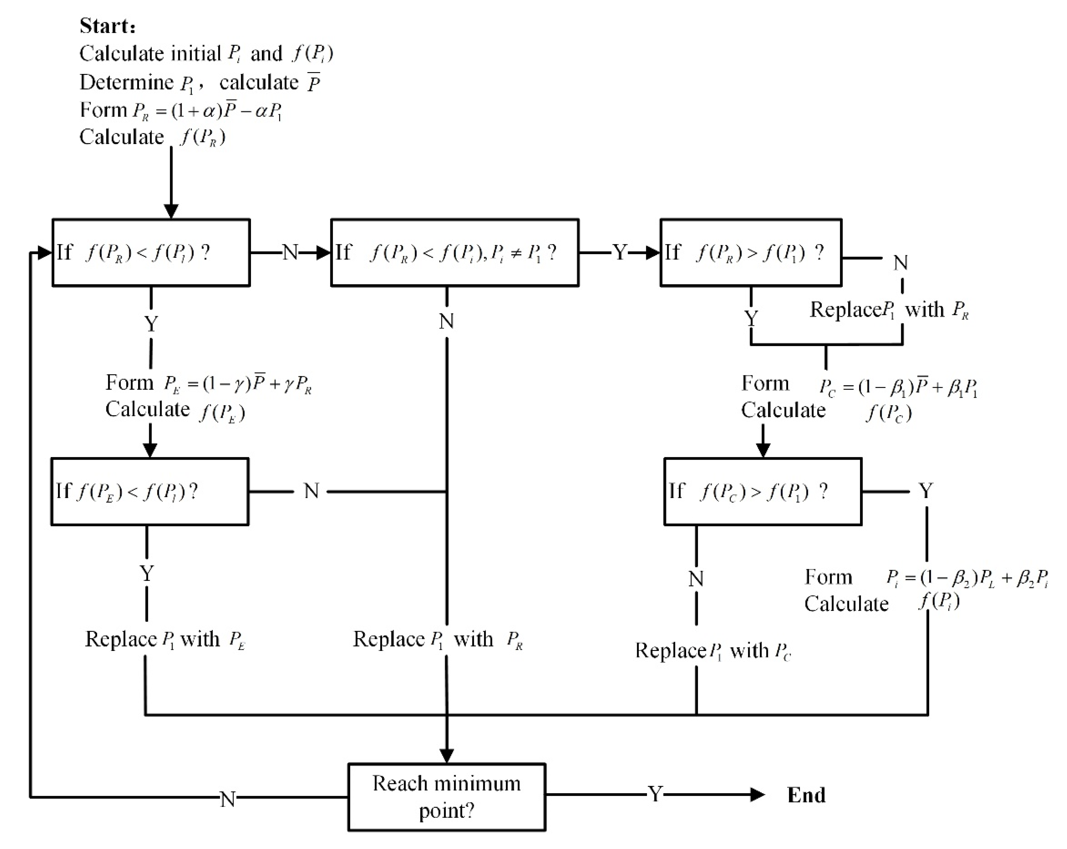
As the purpose of applying the PID controller is to improve the robustness of the outputs’ reference tracking performance, the Nelder-Mead method is thus considered a suitable alternative. The Nelder-Mead method is a subtle optimizing algorithm for optimum tracking [
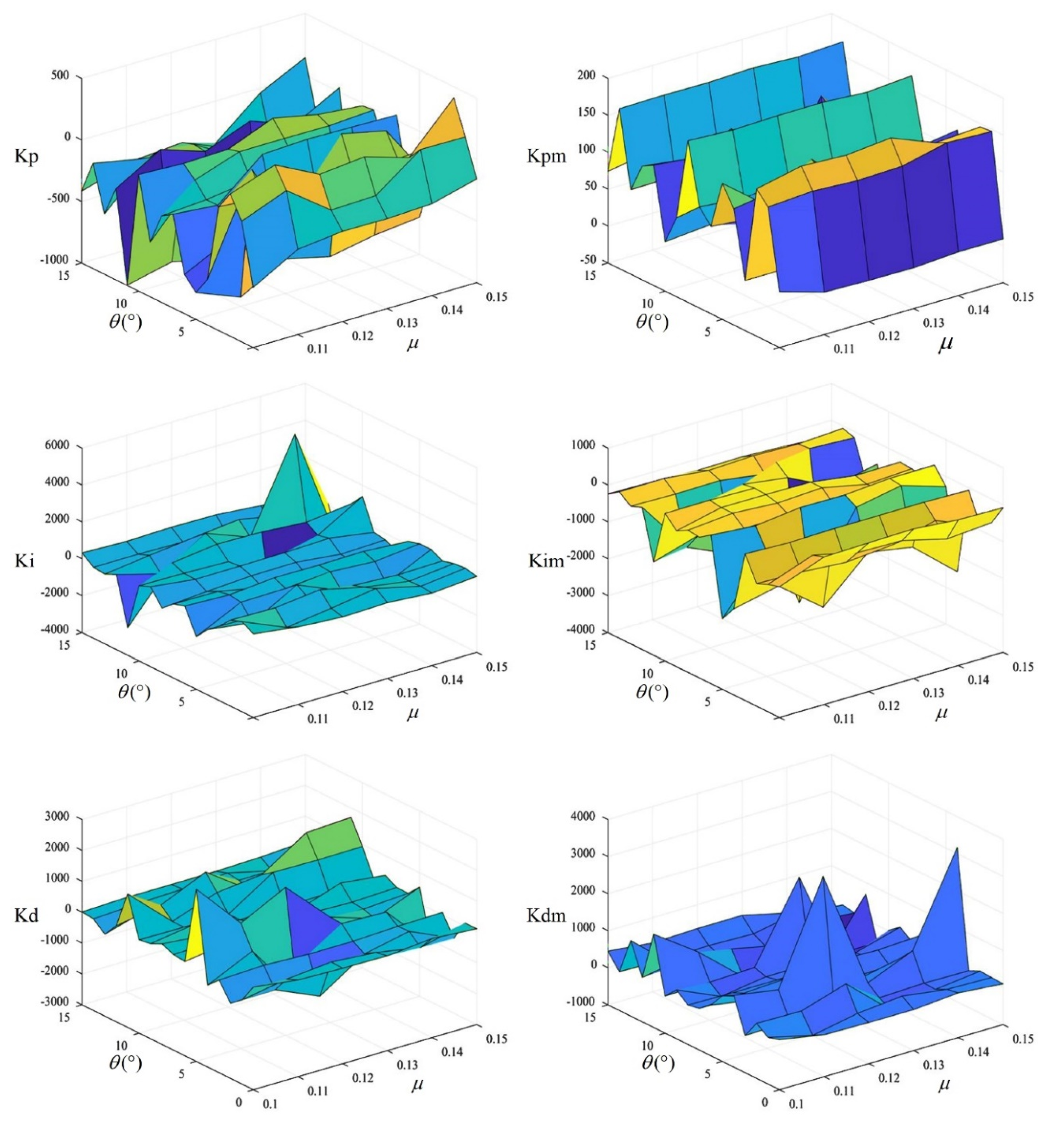
20]. The algorithm employs a geometric construct called a simplex to minimize the cost function. However, the Nelder-Mead method requires a large amount of calculation, which makes the algorithm incapable of being directly applied in the vehicle control unit, let alone when the driving condition varies. Storing the tuned parameters in PID maps is a commonly used method for reference tracking feedback control. The PID maps that store the calibrated PID parameters of different working conditions could be easily implemented in the transmission control unit. Moreover, the PID map is an effective method to avoid integration drift. With the perturbed parameters well estimated, the exports of the maps will be able to improve the robustness of the output reference tracking performance.
The proposed tuning method is a simplified alternative optimization method similar to the time-domain optimal-tuning PID control concept proposed for SISO system in [
21], which has been considered a reliable, optimal solution to solve industrial problems, but several extensions and advantages could be observed:
The proposed tuning method is concise and applicable in both SISO and TITO systems.
The tuned PID parameters stored in the maps are proven by simulations or experimental tests to have satisfying system responses, which makes the performance prediction part negligible.
It requires little knowledge of the system identification and other complicated, theoretical control laws or algorithms from engineers.
The objective of this paper is to improve the controller’s robustness performance of the AMT with the gearshift assistant mechanism concept against the variation of the road gradient and the friction coefficients. The perturbed parameters are modeled in the numerical models. Based on a decoupling controller and a disturbance compensator, online adjustable PID maps are applied to cope with the perturbed parameters. In the tuning process, the cost function taking the PID parameters as independent variables is established, and the minimum value of the cost function is calculated by using the Nelder-Mead method. The PID parameters are then automatically tuned when the minimum value is reached. Weighting coefficients are inserted into the cost function; by changing the weighting coefficients, the system performance varies as well. The designed controller is tested on a whole powertrain simulation model; the results show that the controllers are robust to the perturbed parameters, which makes the gearshift assistant mechanism a promising mechanism for torque gap filling.
2. Principle Architecture and Working Theory of the Gearshift Assistant Mechanism Concept
As shown in
Figure 1, the gearshift assistant mechanism consists of an electric motor, an epicyclic mechanism, and a synchronizing clutch. The motor directly transmits power to the output shaft through a pair of gears, namely the complementary gear. Meanwhile, the power of the motor will also be transmitted to the secondary shaft of the gearbox through the epicyclic mechanism and the synchronizing clutch. The synchronizing clutch connects the output shaft of the gearbox to the secondary shaft. The epicyclic mechanism transmits the speed and torque of the output shaft to the driven clutch plate (i.e., the clutch plate on the output shaft side) of the synchronizing clutch at a certain gear ratio. After the synchronizing clutch starts to engage, the secondary shaft in the AMT gearbox is affected by the clutch friction torque to change the speed, and the speed of the preshift gear will be changed by the toque transmitted through the complementary gear pair. When the gear-to-gear ratio of the preshift gears is equal to that of the epicyclic mechanism gear ratio, the preshift gears will be synchronized with the output shaft due to the engagement of the synchronizing clutch, and the engine speed will be simultaneously synchronized with the vehicle speed.
As shown in
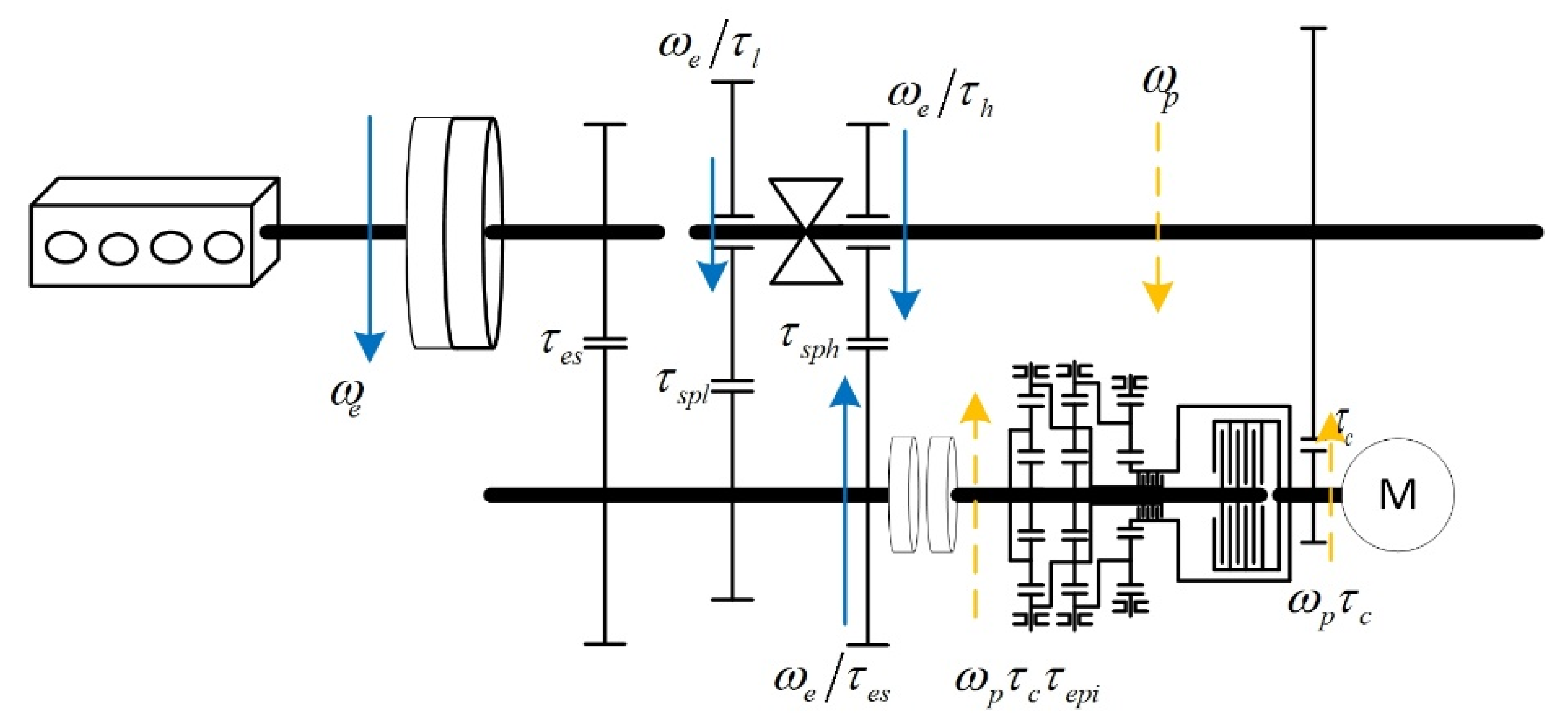
Figure 2, the kinematics of AMT with the gearshift assistant mechanism could be described by two angular velocities,
and
, as:
where
is the angular velocity of the engine side clutch plate,
is the angular velocity of the engine side clutch plate,
is the angular velocity of the lower gear step idling gear on the output shaft,
is the angular velocity of the higher gear step idling gear on the output shaft,
is the gearbox output shaft angular velocity,
is the angular velocity of the electric motor,
is the gear ratio of the lower gear step,
is the gear ratio of the lower gear pair,
is the gear ratio of the higher gear step,
is the gear ratio of the higher gear pair,
is the epicyclic mechanism gear ratio,
is the engine output shaft to secondary shaft gear ratio, and
is the torque complementary gear pair gear ratio.
Taking the upshifting process as an example, the epicyclic mechanism and the complementary gear pair are designed as:
The target is to synchronize the output shaft angular velocity
and the preshift gear angular velocity
, which must satisfy the following equation:
The above equation shows the kinematic theory of shifting with the proposed mechanism. As shown in
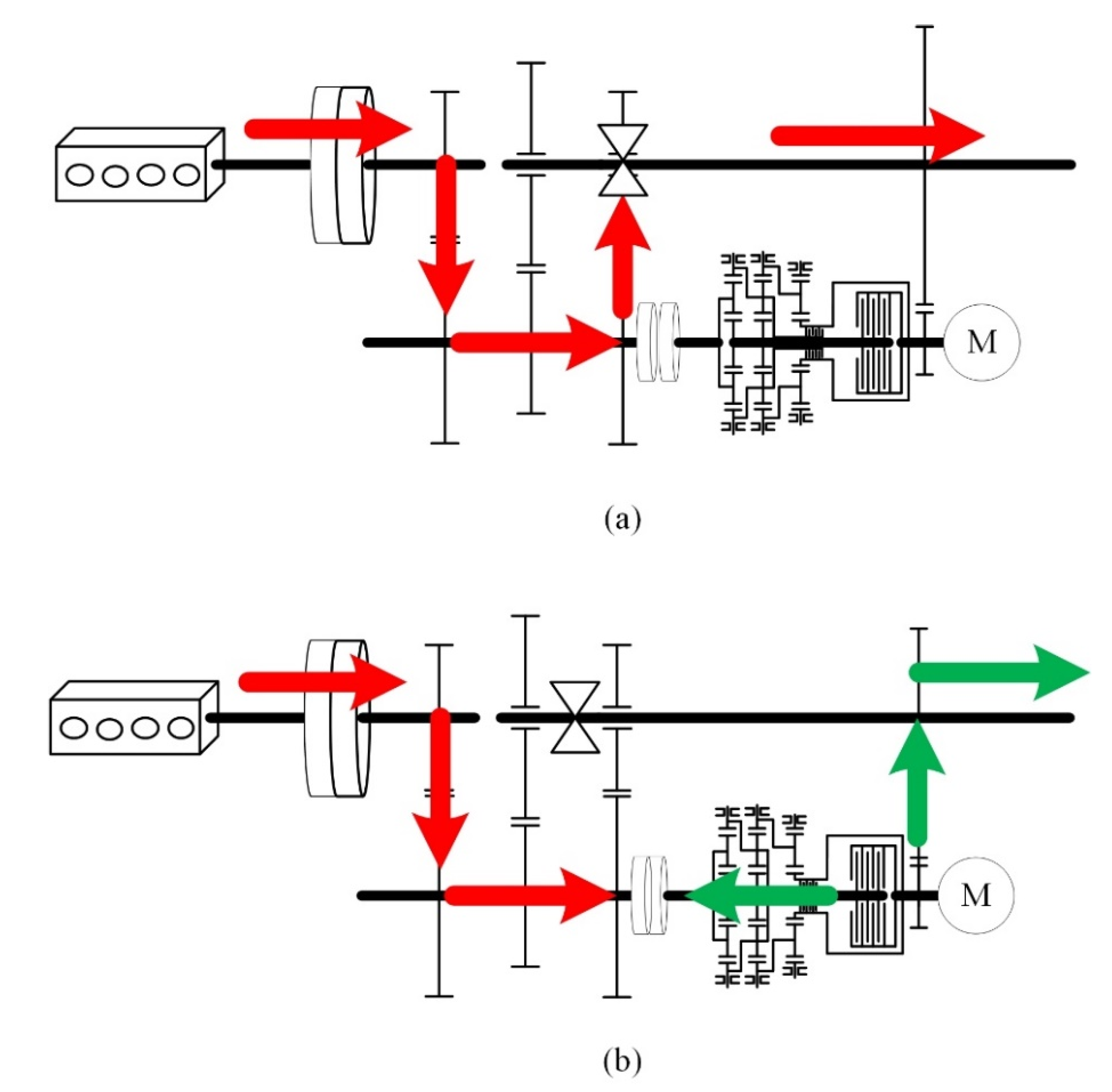
Figure 3a, the transmission operates in the same manner as traditional AMT in fixed gear steps. In comparison, the gearshift assistant mechanism idles along with the output shaft, which brings extra power loss according to the inertia effect.
Figure 3b shows the shifting process of AMT with the gearshift assistant mechanism. The engine torque is interrupted, and the power source of the output shaft is substituted by the motor torque. When the torque gap is being filled, the engagement of the synchronizing clutch is interfered by the motor torque and the engine torque.
In the shifting process, as shown in
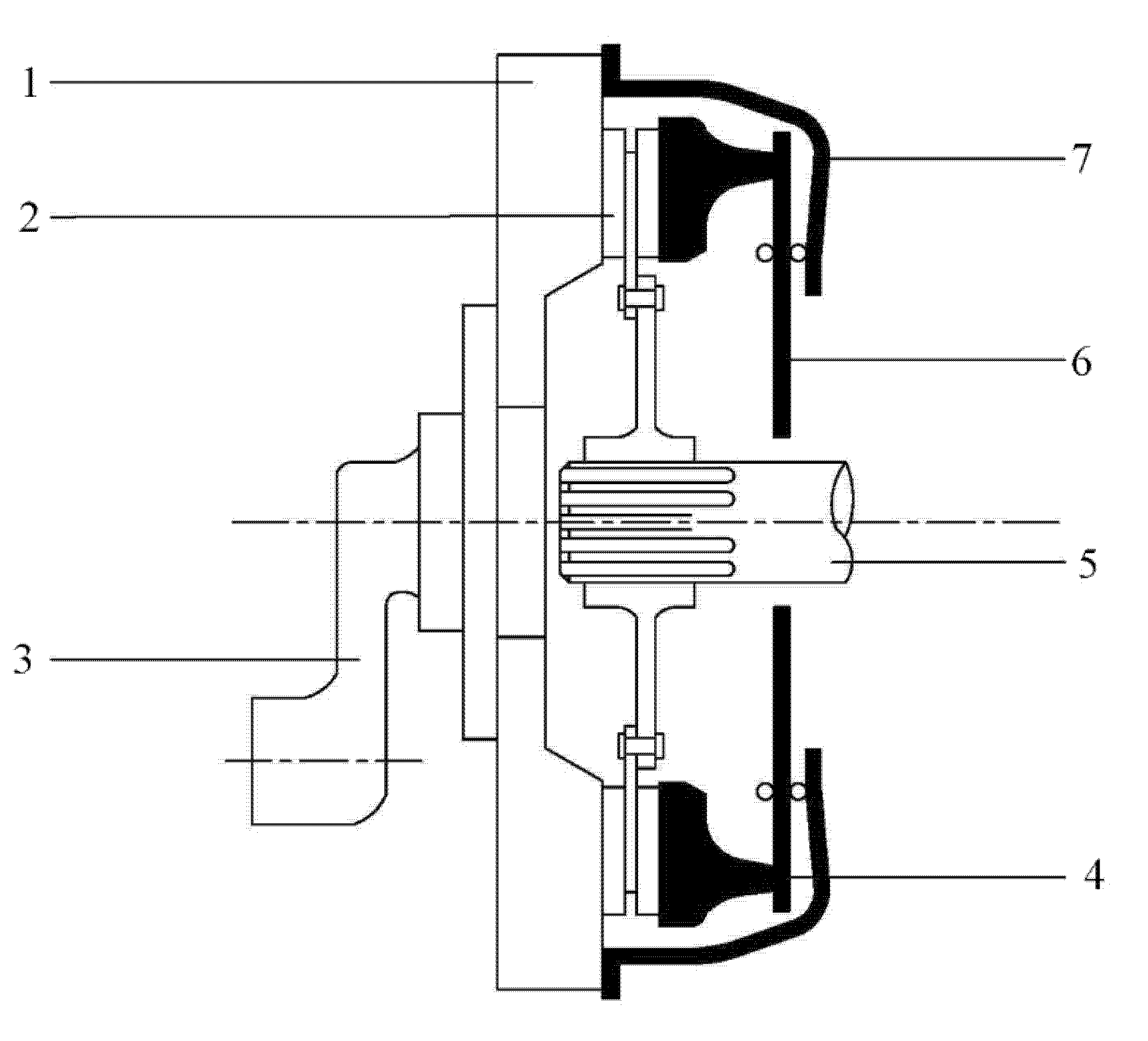
Figure 4, the AMT with a gearshift assistant mechanism has two degrees of freedoms: the angular velocity of the engine side clutch pad
and that of the output shaft side clutch pad
. The dynamics of the clutch pads could be described as follows:
where
is the engine torque;
is the friction torque on the synchronous clutch;
is the motor torque;
is the vehicle driving resistance torque;
is the equivalent rotational inertia of the engine, main clutch, and secondary shafts;
is the equivalent rotational inertia of the remaining transmission;
is the equivalent damping coefficient of the engine, main clutch, and secondary shafts; and
is the equivalent damping coefficient of the remaining transmission. The function sign outputs 1 when the value in parentheses is positive, otherwise −1.
From the dynamic equations, it could be observed that the change of the engine side clutch pad’s angular velocity is decided by and , while the change of the output shaft side clutch pad’s angular velocity mainly hinges on , , and .
The friction torque will be produced once the clutch pads start to engage. In association with Equation (3), the synchronization will be able to be accomplished by properly coordinating the engine torque, the friction torque, and the motor torque.
If the gear ratios of the epicyclic mechanism satisfy Equation (2), the engagement of the synchronizing clutch, which takes the clutch torque capacity to be sufficient, will ensure the synchronization of the preshift gear and the output shaft. It is worth noting that the engine torque is set to be zero in the shifting process to minimize the size of the gearshift assistant mechanism since such a setting requires a lower torque capacity from the mechanism. Consequently, the proposed mechanism, especially the synchronizing clutch, will only have to overcome the equivalent moment of inertia and other resistant torques of the engine and its connected parts to accomplish the foregoing process.
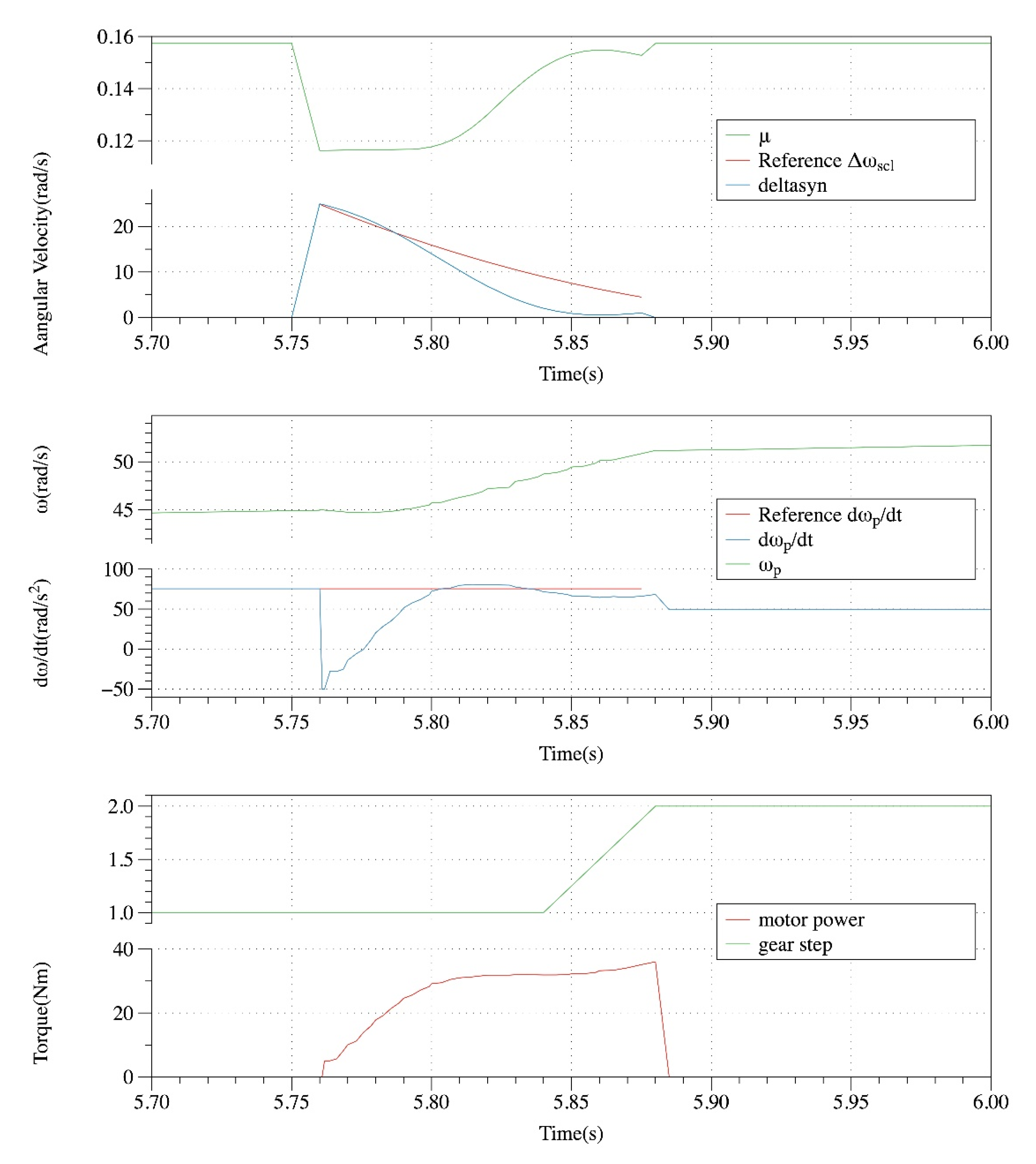
The shifting process after the AMT is equipped with the gearshift assistant mechanism can be summarized as follows: (a) The epicyclic mechanism output gear ratio is required for shifting; (b) the synchronizer is disconnected, and the gearbox is in neutral; (c) The motor starts to work and provides the torque, while the synchronous clutch starts to engage simultaneously; (d) the synchronizer locks the target gear, and the gearbox outputs the target gear ratio; (e) the engine restores power, and the synchronizing clutch is disengaged.
5. Conclusions
In aiming to improve drivability and alleviate the deteriorated coupling effect between the clutch and motor torque caused by road gradient variation and friction coefficient fluctuation in the AMT with the gearshift assistant mechanism, PID feedback controllers are employed in this paper in association with a decoupling controller and a disturbance compensator. The PID controller parameters are tuned based on the powertrain mathematical model by minimizing the cost function in relation to the outputs’ tracking errors with the Nelder-Mead method. By storing the tuned parameters in relation to different friction coefficients and road grades in the PID maps, the PID controllers become adjustable online and easy to be planted in the transmission control unit.
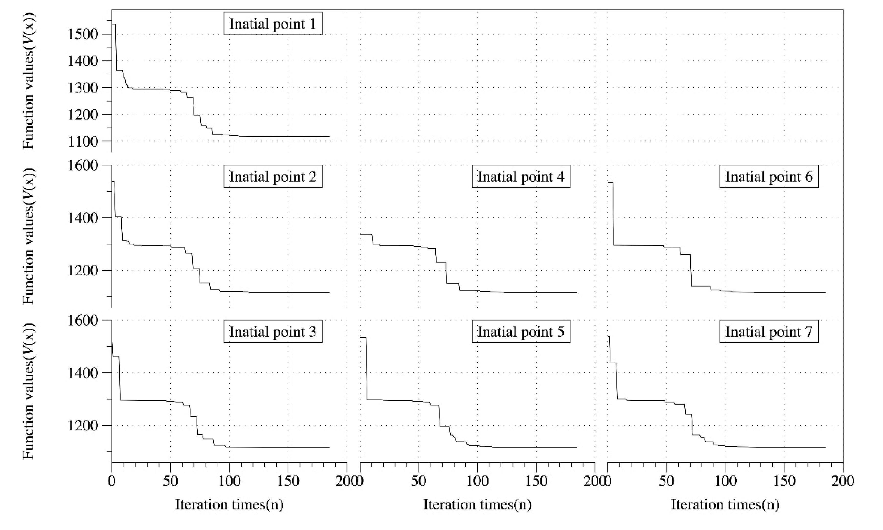
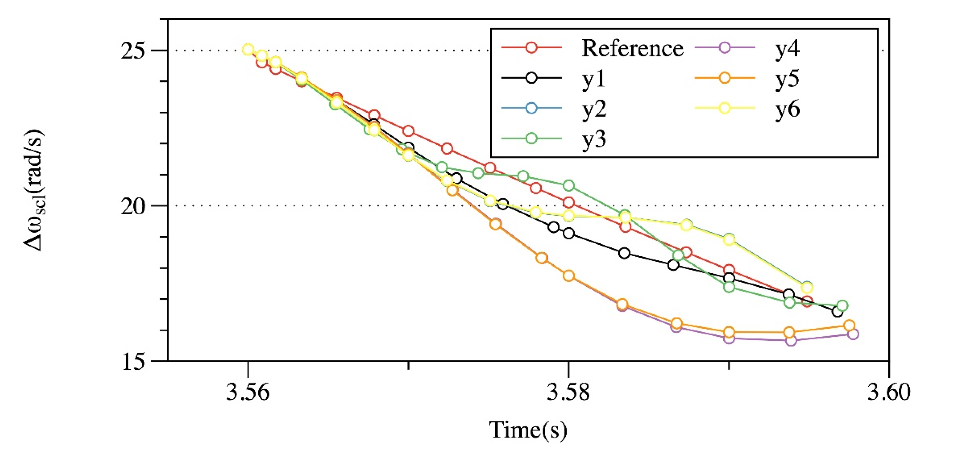
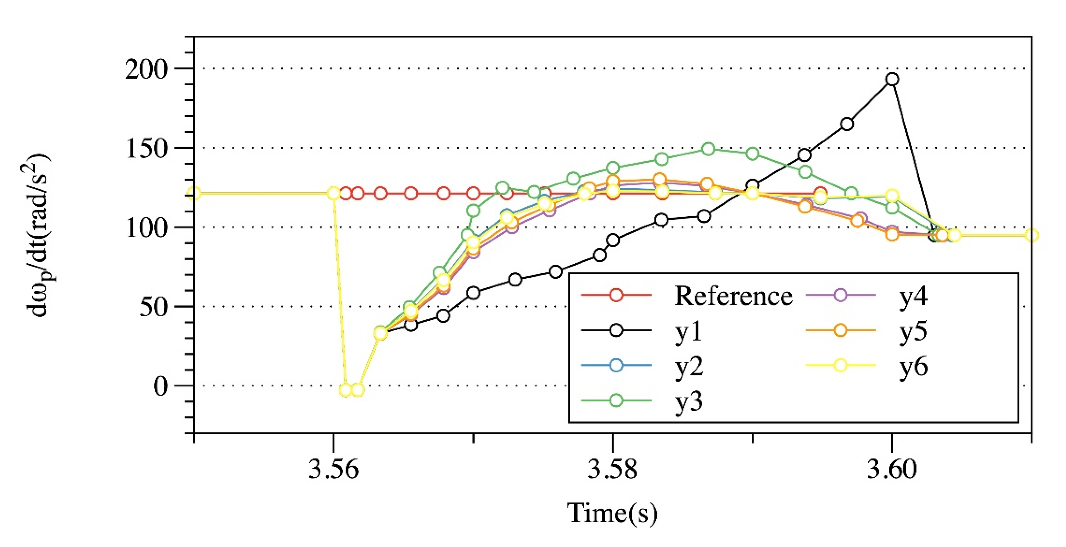
Simulations have been carried out to analyze the PID parameter tuning process, the shifting performance, and the improvement of the robustness. Simulation results show that the outputs’ reference tracking ability improves as the cost function values decrease, and it deteriorates as the corresponding weighting parameters decrease, which proves the effectiveness of the cost function. In association with the analysis on the upshift performance, it could be observed that with the same initial points, namely the same termination threshold, the output’s reference tracking ability varies obviously with the weighting parameters changed within specific ranges. With the same initial points, namely the same weighting parameters, decreasing the terminating threshold in a limited range significantly improves the outputs’ tracking ability; with the same weighting parameters and the same termination threshold, the closer the initial points are to the optimal points, the fewer iteration times will be required to obtain similar tracking ability. With the assumption that the perturbed parameters were well estimated, the simulation results show that the proposed controllers enhance the outputs’ tracking ability against the varying friction coefficient and the road grade.
The AMT with a gearshift assistant mechanism has great potential to become a fast, uninterrupted powershift transmission. Future works will concentrate on the following aspects: (a) optimization of the gear selector, since the traditional synchronizers have been replaced by the synchronizing clutch; (b) optimization of the shifting logics and operating modes to minimize the energy consumption in different driving cycles; (c) developing proper controllers to achieve a seamless power source switch between the engine and the electric motor; and (d) carrying out experimental validation on the proposed conceptual mechanism.
