Article

Analytical Approach of a Pure Flow Mode Serpentine Path Rotary Magnetorheological Damper

by
Rivananda Rama Satria
,
U. Ubaidillah
* and
Fitrian Imaduddin
Mechanical Engineering Department, Universitas Sebelas Maret, Jalan Ir. Sutami 36A, Kentingan, Surakarta 57126, Indonesia
*
Author to whom correspondence should be addressed.
Actuators 2020, 9(3), 56; https://doi.org/10.3390/act9030056
Submission received: 17 June 2020 / Revised: 19 July 2020 / Accepted: 20 July 2020 / Published: 21 July 2020
(This article belongs to the Section Actuators for Robotics)

Abstract

:
This paper has two main goals in the development of a novel flow-mode magnetorheological brake (MRB): (1) produce a mathematical model of a flow-mode MRB and (2) predict the torque density of the proposed MRB compared to the other type of MRB. In this design, the flow mode MRB is made by screw pump to make the Magnetorheological Fluid (MRF) flow through the radial and annular channel. The serpentine path flux is developed in the proposed MRB to make the annular channel an active region as well. With the proposed design concept, the work of a pure flow-mode serpentine path MRB can be accomplished. In this study, Finite Element Method Magnetics (FEMM) is used to calculate the magnetic field applied to the active regions and analytical approach used to obtain the output damping torque. The simulation results show that the magnetic fluxes flow through the radial channel and annular channel as well. The radial and annular channel is activated, which led to higher output damping torque. The mathematical modelling shows that the helical angle of the screw pump significantly affects the damping torque. The results show that the output damping torque density can be adjusted from 42.18 N/mm2 in the off-state with 0 rpm to around 40,518.96 N/mm2 at 20 rpm. The torque density of the proposed MRB is higher than the shear mode MRB.

1. Introduction

Magneto-rheological (MR) materials are classified as smart materials because they can change their properties when subjected to a magnetic field [1]. MR materials comprise magnetic particles and its matrics. MR Elastomer and MR Fluid (MRF) are examples of MR materials. MR Elastomer consists of a magnetic particle and an elastomer such as waste tyre rubber [2] and natural rubber [3] as the matrics. On the other hand, MRF has magnetic particles with liquid-phase matrics [4]. MRF can change its form from liquid to gel and its properties when a magnetic field is applied to it [5]. Its viscosity doubles when subjected to a magnetic field, due to the increase in yield shear stress [6]. MRF has received much attention during the two past decades, as it has huge potential for daily needs application.
For example, MRF can be applied as MR seat suspension [7], MR clutch [6], muscular rehabilitation device [8] and MR dampers [9]. MR dampers are classified as a semi-active damper, as they can control the viscosity of MRF that will affect their stiffness. The stiffness of an MR damper will affect the amount of force it can exert for damping.
A semi-active damper has a huge advantage over a passive damper. The viscosity of a semi-active damper can be adjusted by means of the input current, which leads to a controllable output damping force. Moreover, a semi-active damper has a larger dynamic range too [10]. A conventional viscous damper contains fluid that helps the structure to dissipate the kinetic energy caused by the vibration into heat energy, which leads to an increase in damping force. In particular, an MR damper is filled with MRF. When MRF is affected by magnetic field, the particles are arranged in a pattern and the fluid behavior changes from being linear viscous to semi-solid in milliseconds [11].
In general, there are four basic working modes of MR dampers: the shear mode [12], the flow mode [13], the squeeze mode [14], and a combination of the shear and flow modes [15]. The flow-mode MR dampers use the MRF to make it flow through a channel where a magnetic field acts perpendicularly to the direction of flow. The shear-mode MR dampers use a moving wall that moves perpendicularly to the direction of the magnetic field, creating friction between the wall and the MRF. The squeeze mode uses a moving wall that moves parallel to the direction of the magnetic field.
MR dampers can be classified into linear MR dampers [16] and rotary MR dampers [17] based on their mechanism and output. Linear MR dampers move on the translation direction and their output is damping force. Rotary MR dampers move on the rotation direction and their output is damping torque. Linear MR dampers have already been applied as vehicle shock absorbers [18], prosthetic knee [19], and civil application [20], but the application of linear MR dampers on braking systems is difficult [21]. Moreover, linear MR dampers have some limitations, such as huge installation space [22] and restriction of stroke because of the risk of buckling of the damper rod [23]. Therefore, many researchers focus on developing rotary MR dampers to complete the research of MR dampers’ application.
In general, the research aims to optimize the performance of rotary MR dampers in shear mode. The damping torque that can be produced by the shear-mode rotary MR dampers depends on the structure of rotary MR dampers and plastics viscosity of MRF [23]. Shear-mode rotary MR damper structures that have already been developed are drum type, disc type, and hybrid type [9]. Many researchers have investigated the optimization of a rotary MR damper. Huang et al. [24] studied the drum-type rotary MR damper, which utilizes the surface area of annular gaps of MRF to generate the output damping torque. Li et al. [25] studied the disc-type rotary MR damper, which utilizes the surface area of radial gaps to produce the damping torque. Gerick et al. [26] proposed the serpentine path drum type to increase the active region of the annular channel. Serpentine configuration optimizes the active area of annular gaps, which leads to a higher output damping torque [27]. Hidayatullah et al. [28] proposed a serpentine path T-shaped rotor rotary MR damper, which is a combination of the drum-type rotary MR damper and disc-type rotary MR damper, in which the active surface area of MRF can be increased to generate higher output damping torque.
However, shear-mode rotary MR dampers produce limited damping torque, because of the limited yield shear stress that can be produced by MRF [21]. Flow-mode rotary MR dampers are not just limited by the yield stress of MRF but also affected by the turning speed of the rotor. Based on that idea, Yu et al. [21] proposed a helical flow rotary MR damper, which works in both shear and flow modes. The result shows that the proposed helical flow rotary MR damper has a more compact structure than the comparative shear-mode rotary MR damper. Based on the proposed rotary MR damper proposed by Gurocak et al. [26] and Yu et al. [21], this paper introduces a flow-mode serpentine path rotary MR damper. In this research, the damping torque that can be achieved by a flow-mode serpentine path rotary MR damper would be predicted. Lastly, a comparison between the torque density of the proposed rotary MR damper with another rotary MR damper was presented in the end of discussion.

2. Design of a Flow-Mode Serpentine Path Rotary MR Damper

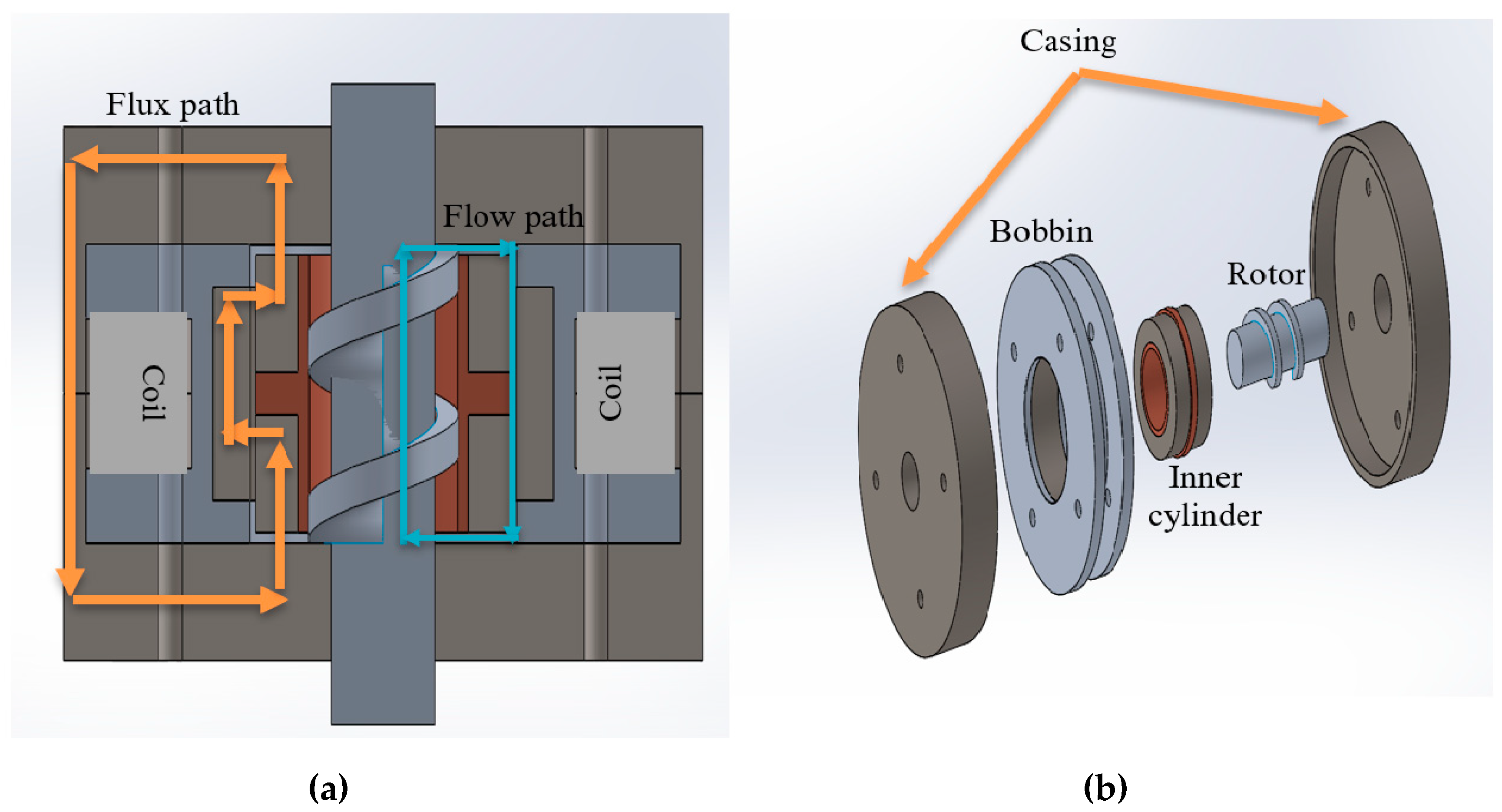
2.1. Structural Design

For this rotary MR damper, two concepts are adopted in this study. The first concept is a helical flow rotary MR damper model introduced by Yu et al. [21]. In helical flow construction, a screw pump rotor is used to deliver the MRF through the annular channel. The construction also consists of another channel that works on shear mode. The second concept is serpentine flux MRB (MR Brake) proposed by Gurocak et al. [26]. Serpentine flux MRB achieves higher torque without increasing the size of the MRB by broadening the active surface area of MRF with the magnetic flux [18]. Strategically, the magnetic conductive material and non-magnetic conductive material configuration can bend the magnetic flux.
The most common way to improve the performance of a shear-mode rotary MR damper is to maximize the active area of MRF or to optimize the magnetic field that affect MRF [29]. Increasing the magnetic field affecting MRF will lead to a higher yield shear stress, but it also will lead to larger dimensions of rotary MR damper.
In this study, a flow-mode rotary MR damper with serpentine flux path was proposed. The proposed rotary MR damper aims to improve the output damping torque by optimizing the magnetic field density and the active area of MRF. Moreover, the idea of transforming the shear-mode serpentine path rotary MR damper into a flow-mode serpentine path rotary MR damper was based on the fact that flow-mode rotary MR damper output damping torque was not limited by the dimensions of the rotary MR damper.
As shown in Figure 1a, the rotor uses screw pump and serpentine flux configuration. The orange line shown in Figure 1 presents the magnetic flux path of the proposed rotary MR damper. The outer part of the bobbin was made of non-magnetic materials to prevent the magnetic flux from entering the bobbin. The rotor was also made of non-magnetic material, to prevent the magnetic flux from affecting the rotor, because it will lower the magnetic field that affects the MRF.
Based on Figure 1b, the proposed rotary MR damper consists of four main parts, each corresponds to the casing, bobbin, inner cylinder, and the rotor. The screw pump rotor is designed to push the MRF to flow along the channel as shown by the blue line of Figure 1a. The inner cylinder is designed to be a stator. For fixing the position of the inner cylinder, it will be pinned with the casing so it that remains in that position. The coil winding to the bobbin will generate the magnetic field required to affect the MRF.
The dimensions of the proposed rotary MR damper are 30 mm of radius with 25 mm of thickness. The maximum current applied to the coils is 2 A. The properties of MRF-132DG, a list of parts for the proposed MRB, and the dimensions of each part are shown in Table 1, Table 2 and Table 3, respectively.

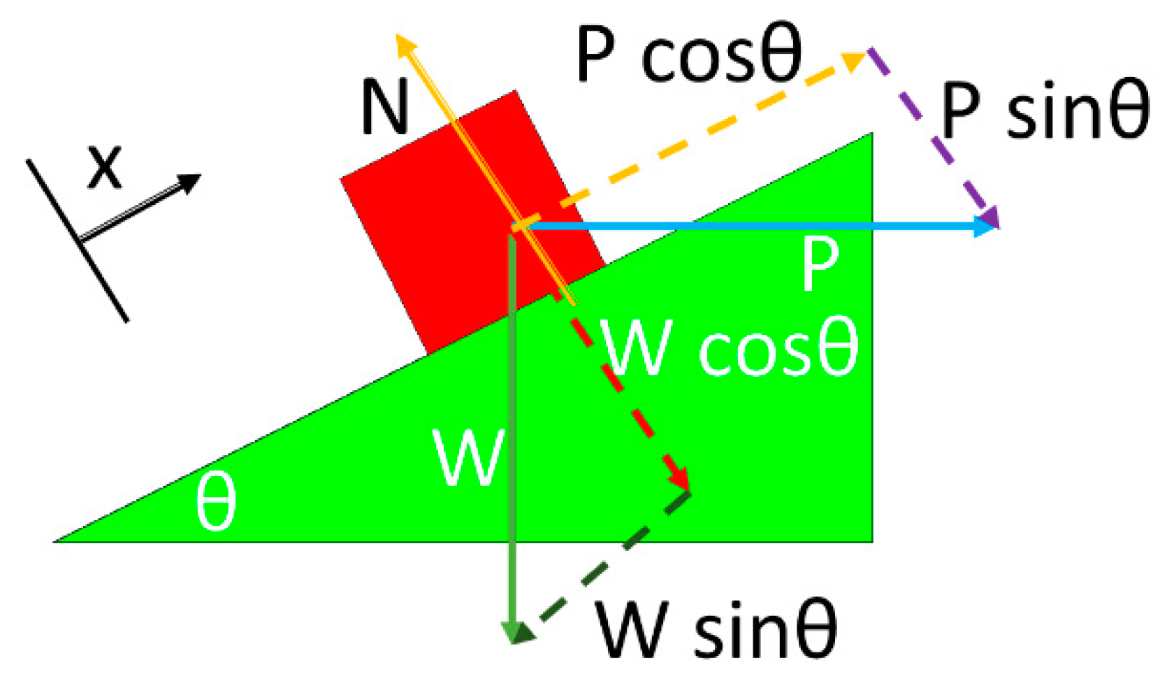
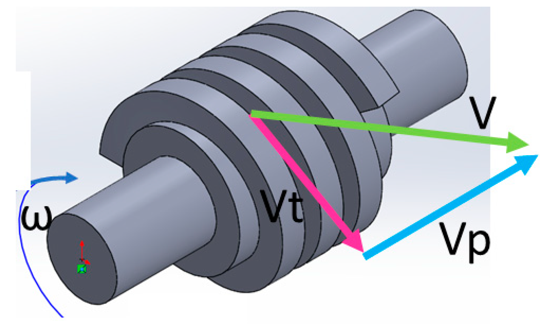
2.2. Torque Analysis

Two components of total output damping torque are generated by the pressure drop caused by the flow of MRF and the shear mode between the rotor and the inner cylinder. For the output damping torque generated by the flow of MRF, it is needed to figure out the torque required to run the screw pump. For the screw pump, the torque general equation is expressed in Equation (1):
T   = P ×   r
where P is tangential force and r is the average radius of screw.
Figure 2 shows the free body diagram of the screw pump. It is known that the relation between P and W is determined using Newton’s law. It is assumed that there is no friction between the screw and the inner cylinder. So, it can be assumed that the N is zero. The relationship between P and W is expressed in Equation (2):
P cos θ W sin θ = 0 P = W tan θ
where,
tan θ = p π d
Equation W is the load needed to be lifted by the screw pump. The value W can be found using Equation (4):
W = Δ P A p
where ΔP is the total pressure drop caused by both annular channel and radial channel and Ap is the surface area perpendicular to the direction of ΔP. Assume that there is no infiltration due to the small clearance between screw and inner cylinder, Ap can be expressed as shown in Equation (5):
A p = π ( r d o 2 r d i 2 )
As shown in Figure 1, it can be seen that the proposed rotary MR damper consists of one annular channel and two radial channels. Annular viscous pressure drop and yield pressure drop values are expressed in Equations (6) and (7), respectively. Furthermore, radial viscous pressure drop and yield pressure drop are expressed by Equations (8) and (9), respectively [30]:
Δ P v i s c o u s   a n n u l a r = 6 η Q L π d 3 R
Δ P y i e l d   a n n u l a r = c τ ( B ) L d
Δ P v i s k o s   r a d i a l = 6 η Q π d 3 ln ( R 1 R 0 )
Δ P y i e l d   r a d i a l = c τ ( B ) d ( R 1 R 0 )
where
c = 2.07 + 12 Q η 12 Q η + 0.8 π R d 2 τ ( B )
So, ΔPtotal created on the proposed rotary MR damper is expressed by Equation (11):
Δ P t o t a l = Δ P v i s k o s   a n n u l a r + Δ P y i e l d   a n n u l a r + 2 ( Δ P v i s k o s   r a d i a l + Δ P y i e l d   r a d i a l )
The yield shear stress of MRF can be predicted by using the Bingham model. Equation (12) expresses the Bingham model [31].
τ = τ ( B ) + η r θ ˙ d
where τ is the yield stress of MRF, τ(B) is the yield stress due to the magnetic field, and η r θ ˙ d is the yield stress when there is no magnetic field applied. However, the value of η r θ ˙ d in this research can be neglected, because of the low rotational speed of the proposed rotary MR damper.
τ(B) is τ as magnetic field function. Every kind of MRF has different characteristics of yield stress over the magnetic fields. In this research, MRF-132DG was chosen as the MRF. The relationship between magnetic field and the shear stress of MRF-132DG is expressed in Equation (13) [28].
τ = 52.962 B 4 176.51 B 3 + 158.79 B 2 + 13.708 B + 0.1442
FEMM (Finite Element Method Magnetic) is used to identify the distribution of magnetic field that affects MRF-132DG in both annular and radial channels. From the simulation result, the graphics showing the distribution of magnetic field will appear; thus, the average magnetic field affecting each channel could be calculated.
The proposed rotary MR damper uses a screw pump to deliver the MRF. Therefore, it is compulsory to find the value of Q in the screw pump. Equation (14) expresses the value of Q, assuming there is no infiltration between the screw pump and the inner cylinder, because of the relatively small clearance.
Q = A p v p
Figure 3 shows the velocity polygon of the screw pump. Since it is needed to find out the value of vp to determine the value of Q, it is compulsory to investigate the value of vp. The value of vp is expressed by Equation (15):
v p = n r o t o r p
where p is already defined by Equation (3).
p = π d tan θ
From the modelling on Equations (1)–(16), the value of damping torque that can be produced by the proposed rotary MR damper can be expressed as Equation (17) below:
T = ( 6 η ( n r o t o r π d tan θ ) π ( r d O 2 r d I 2 ) L π d 3 R + ( 2.07 + 12 ( n r o t o r π d tan θ ) π ( r d O 2 r d I 2 ) η 12 ( n r o t o r π d tan θ ) π ( r d O 2 r d I 2 ) η + 0.8 π R d 2 τ ( B ) ) τ ( B ) L d + 2 ( 6 η ( n r o t o r π d tan θ ) π ( r d O 2 r d I 2 ) π d 3 l n ( R 1 R 0 ) + ( 2.07 + 12 ( n r o t o r π d tan θ ) π ( r d O 2 r d I 2 ) η 12 ( n r o t o r π d tan θ ) π ( r d O 2 r d I 2 ) η + 0.8 π R d 2 τ ( B ) ) τ ( B ) d ( R 1 R 0 ) ) ) π ( r d O 2 r d I 2 ) d tan θ 2
where T is the output damping torque, η is the viscosity, nrotor is the angular speed, p is the screw pitch, rdO is the outer radius of the screw, rdi is the inner radius of the screw, L is the length of annular region, d is the gap width, R is the radius of annular channel, τ(B) is the yield shear stress of MRF, R0 is the inner radius of radial channel, and R1 is the outer radius of radial channel.
The rotor and the inner side of the inner cylinder were made of non-magnetic conductive material; the magnetic field does not affect the MRF inside the rotor. Therefore, the output damping torque generated by the shear mode can be neglected.

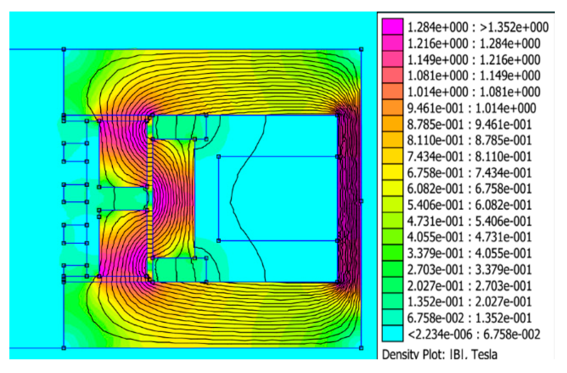
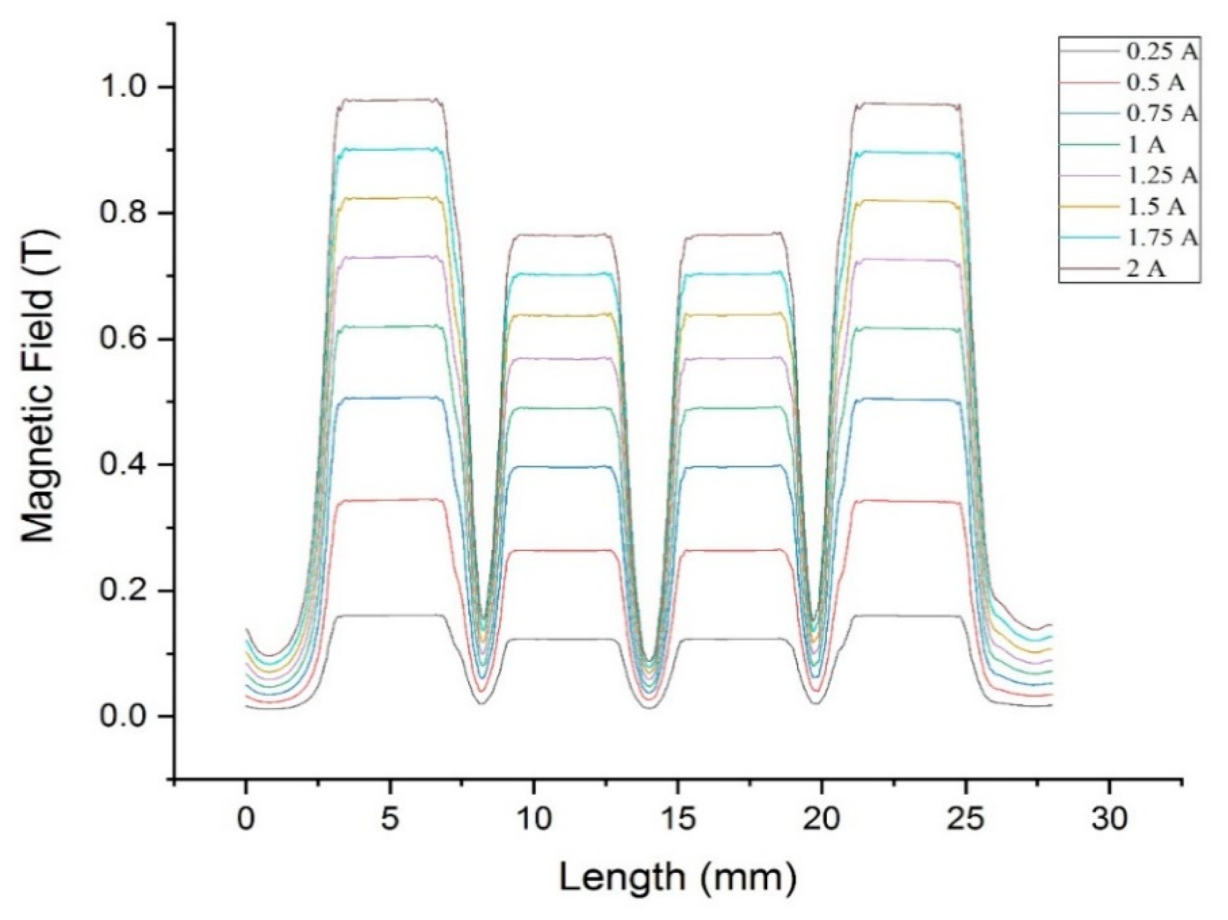
3. Magnetic Field Analysis

For determining the shear stress of MRF, it is essential to analyze the magnetic distribution of the rotary MR damper. There are two methods to analyze the magnetic distribution of the model: the analytic method and the finite element method. The analytic method is a simplified method to obtain the magnetic field intensity. To predict the magnetic field, it is needed to determine the number of magnetic fluxes produced by the coil. Equation (18) expresses the relation between magnetic field and magnetic flux.
B = ϕ/A cos α
Here, B, ϕ, A, and cos α represent the magnetic field, the number of magnetic fluxes, the surface area, and the angle between the magnetic flux and the surface area, respectively. The number of magnetic fluxes produced depends on the reluctances of the magnetic circuit, input current, and the number of turns of the coil used. Equation (19) represents the electromagnet force equation.
ΣF = ϕΣR = NI
Here, ϕ, R, N, and I represent the number of magnetic fluxes, the magnetic reluctances, the number of turns of the coil, and the input current, respectively. The value of magnetic reluctance is affected by the distance that the flux passes through, the surface area covered by the flux, and the magnetic permeability of each material. The reluctances of each material can be obtained by Equation (20).
R = L/μA
The analytical method used a linearized approach in magnetic flux calculation. It often provides serious error in prediction, as stated by Yu et al. [21]. To avoid this error, magnetic simulation using a finite element method is then used for the more accurate prediction of magnetic flux. The FEMM has been well known in magnetostatics modelling that has been used so far in magnetorheological devices design. The main function of FEMM is to predict the magnetic flux density in the effective area of braking. Here, the flux density is then used for calculating the shear yield stress of the MR fluids at the on-state condition. Therefore, this simulation is very helpful for MRB torque calculation. Although, it was realized that, in certain condition (for instance, the non-linear characteristic of material), the magnetic computation sometimes results in a serious error, but it could be well managed so far by the manual setting of the material characteristic during simulation.
In this research, FEMM was used to compute the distribution of the magnetic field that affects both annular and radial channels with every variation of current input. The copper wire used in this research was 24 AWG with 300 turns. The current input variation of this research was 0.25 A until 2 A with an increment of 0.25 A. In this model, MRF was flowing through a 0.5 mm gap. Of course, to compute the distribution of magnetic field affecting the MRF, it is needed to create the whole model of the proposed rotary MR damper.
FEMM simulation result is going to be used for identifying the magnetic flux path of the proposed rotary MR damper. As presented in Figure 4, the magnetic conductive material and non-magnetic conductive material configurations of the proposed rotary MR damper could bend the magnetic flux path to create a serpentine path. The screw rotor and the inner part of inner cylinder were made of non-magnetic conductive materials, which forces the focused magnetic flux to bend towards the MRF, leading the MRF gets to receive higher magnetic fields.
Furthermore, the distribution of the magnetic field happening around the MRF channel must be determined by extracting the result into a graphic. Figure 5 presents the graphic of magnetic field distribution all around the gap. It shows the distribution of a magnetic field along the radial and annular channels at every input current variation. The magnetic field result will be used to calculate the yield stress of the MRF. The relationship between the yield stress and the magnetic field is already expressed in Equation (13). Based on Equation (13), the higher the magnetic fields that affect the MRF, the higher will be the yield shear stress.
From the simulation results, the magnetic fields that affect MRF are increasing with every increasement of input current, as expressed in Equation (19). The maximum mean magnetic fields that can be achieved is around 0.82 and 0.67 T in the radial and annular channel respectively at 2 A of input current. It also shows that the magnetic field that affected the radial gaps are higher than that of annular gaps. This caused the larger surface area of annular gaps compared with that of radial gaps. So, the magnetic flux in the radial gaps is more crowded compared to the annular gaps, which led to a higher magnetic field. From Figure 5, it is known that there are variations of magnetic field values in each zone, the estimated shear stress will also be different. Therefore, the value of shear stress used in Equations (6) and (7) will be different from that of Equations (8) and (9).

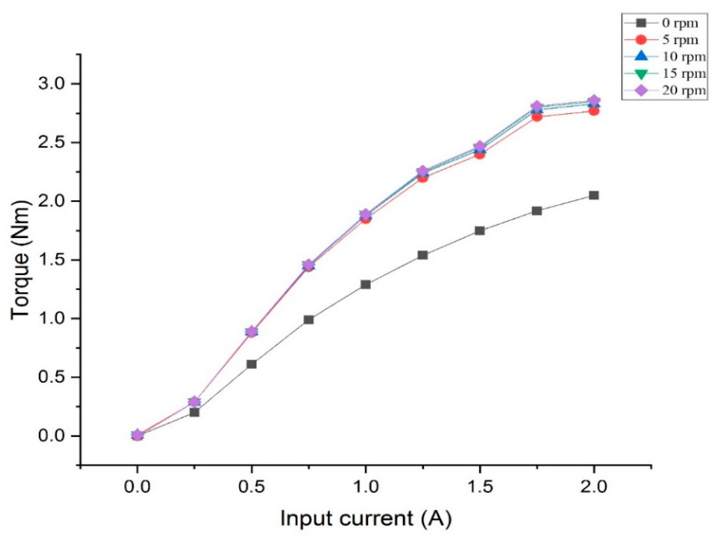
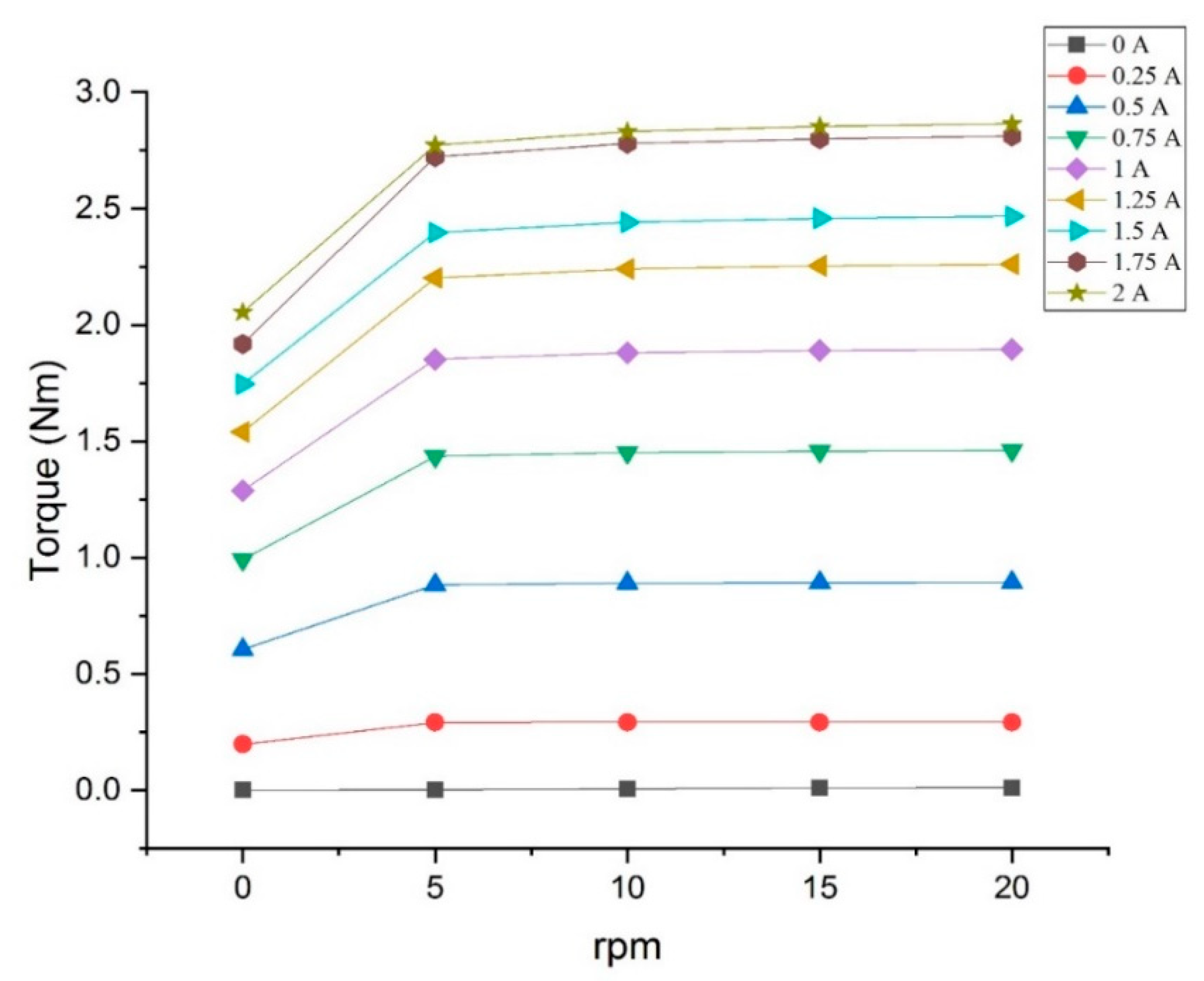
4. Performance Prediction

4.1. Damping Torque Prediction

Figure 6 and Figure 7 present the damping torque prediction of the proposed rotary MR damper. The damping torque prediction was calculated by Equation (17). The magnitude of damping torque is improved by the impact of increasing angular velocity and current input variation, because the pressure drop value will be improved by the yield shear stress increase, as expressed in Equations (6)–(9). The improvement of output damping torque is different at each increment. Figure 6 shows the relation between damping torque with the input current with constant speed. The output damping torque is increasing with the increasement of input current. It is significantly caused by the yield pressure drop is increasing with the increasement of the shear stress of MRF, as expressed by Equations (6)–(9). It shows that there is a massive effect when the current input was increased from 0.25 to 0.5 A and 0.5 to 0.75 A, but the increment of output damping torque at higher current variation is not as huge as lower current variation. This is because the magnetic field, generated by the higher current variation, was not significantly changed at each variation.
Figure 7 shows the relation between damping torque and the rpm with a constant input current. The output damping torque is increasing with the increasement of rpm. It is significantly caused by the yield pressure drop and the viscous pressure drop is increasing with the increasement of the shear stress of MRF, as expressed by Equations (6)–(9). It shows that there is a massive effect when the rpm grows from 0 to 5 rpm, it is caused by the value of Q at 0 rpm, and the value of Q is 0, so there is no viscous pressure drop and the value of c, as expressed by Equation (10), is 2.07. However, when the value of Q is not 0, the value of c is increasing significantly. The off-state damping torque of the proposed rotary MR damper is nearly 0 Nm, and the proposed rotary MR damper works only with low angular velocity. The maximum damping torque that could be achieved by the proposed rotary MR damper is 2.86 Nm at 20 rpm and 2 A current variation.

4.2. Torque Density Prediction

In this study, three rotary MR damper models were selected for comparison. There are 4 figures of merit that can be used to be the comparison parameter, such as dynamic range, torque density, rotor radius, and electric power consumption [8]. Dynamic range and torque density must be maximized, but the power consumption must be kept to a minimum. In this paper, to compare the performance of the proposed rotary MR damper with the other rotary MR damper, torque density is applied. The higher the torque density, the better the performance, because it could produce a higher torque within the limited space.
From Table 4, it can conclude that the proposed rotary MR damper can produce a higher torque density than by the shear-mode rotary MR damper models introduced by Gurocak et al. [26] and Hidayatullah et al. [28]. Compared to the model of Yu et al. [21], the proposed rotary MR damper has equal torque density. However, the rotary MR damper introduced by Yu et al. is working at both flow mode and shear mode, and the shear mode output accomplishes higher damping torque. The proposed rotary MR damper can produce higher torque density. Therefore, we can conclude that the proposed rotary MR damper has a more compact structure.

5. Discussion

The proposed rotary MR damper has a more compact structure than the selected shear-mode rotary MR damper. However, the output damping torque of a flow-mode rotary MR damper, which uses a screw pump to deliver the MRF along the channel, depends on the helical angle of the screw. The relationship between load due to pressure drop and the output damping torque, as expressed in Equation (17), was tan θ, which means that the higher the helical angle design, the higher the output damping torque will be. With a high helical angle, we can transform the load that needs to be lifted to become heavier. Otherwise, the common helical angle was designed to be a low angle. The purpose is to give us a huge advantage by using the low helical angle, by which we can use a relatively small torque to lift the huge load. It is also necessary to give attention to the result of off-state damping torque because it would be bad if the off-state damping torque is already relatively high. So, the design of the optimal helical angle is a concern.
Equations (6)–(9) show that the pressure drop can go higher by using a smaller gap. A smaller gap would give the flow more friction loss that can lead to a higher pressure drop. Moreover, Equations (19) and (20) show that the magnetic flux would increase if the reluctances of each material can be minimized. So, if the width of the gap is designed to be smaller, it would lead to a higher magnetic field. Therefore, designing a smaller gap will give a double advantage to the output damping torque.

6. Conclusions

The research of a flow-mode serpentine path rotary MR damper is conducted. The main conclusions of this research can be stated as follows.
  • The results of FEMM simulation indicate that the configuration of the magnetic conductive material and non-magnetic conductive material of the proposed rotary MR damper could bend the magnetic flux into a serpentine path configuration. It was successful in turning the annular channel into an active region. The activated annular channel would lead to a higher pressure drop and output damping torque.
  • FEMM simulation shows that the average magnetic field can reach 0.82 and 0.67 T in radial and annular channels, respectively, at 2 A of current variation. It shows that the serpentine path will lead to a higher output damping torque, because the yield stress of MRF-132 at a magnetic field of 0.67 T is 38.16 kPa.
  • The proposed rotary MR damper has a more compact structure than the other rotary MR dampers compared. The analytical approach of the proposed rotary MR damper reveals a torque of 2.86 and a torque density of 4.05 × 10⁴ N/m2.
The current design of rotary MR dampers needs further improvement in terms of prototyping, computational work of the control system, as well as in-application implementation. This design has also been opened for other studies to be improved in its design and so on. The open problem would be future promising investigations.

Author Contributions

Conceptualization, U.U.; Methodology, R.R.S.; Writing, R.R.S.; Review, U.U.; Review, F.I. All authors have read and agreed to the published version of the manuscript.

Funding

This research was funded by Ministry of Education and Culture grant number 64/FI/PKS-KCOVID-19.C/VI/2020 And the APC was funded by Ministry of Education and Culture.

Acknowledgments

Authors thank to Hibah LPDP Special Focus on Covid-19 under The Ministry of Finance and The Ministry of Education and Culture 2020 (62/FI/PKS-KCOVID-19.C/VI/2020).

Conflicts of Interest

The authors declare no conflict of interest.

Nomenclature

RMRF channel radius
τ y Shear stress
η Viscosity
ω Angular speed
r o Outer radius of radial channel
r i Inner radius of radial channel
QFlowrate
VpPitch velocity
LpPitch
ΘScrew helical angle
ApCross section
LAnnular channel length
dWidth of channel
ΔPPressure drop
Δ P v i s k o s Viscous pressure drop
Δ P y i e l d Yield pressure drop
cconstants

References

  1. Ubaidillah; Sutrisno, J.; Purwanto, A.; Mazlan, S.A. Recent progress on magnetorheological solids: Materials, fabrication, testing, and applications. Adv. Eng. Mater. 2015, 17, 563–597. [Google Scholar] [CrossRef]
  2. Choi, H.J.; Mazlan, S.A.; Imaduddin, F. Fabrication and viscoelastic characteristics of waste tire rubber based magnetorheological elastomer. Smart Mater. Struct. 2016, 25, 115026. [Google Scholar]
  3. Ahmad Khairi, M.H.; Mazlan, S.A.; Ubaidillah; Ku Ahmad, K.Z.; Choi, S.B.; Abdul Aziz, S.A.; Yunus, N.A. The field-dependent complex modulus of magnetorheological elastomers consisting of sucrose acetate isobutyrate ester. J. Intell. Mater. Syst. Struct. 2017, 28, 1993–2004. [Google Scholar] [CrossRef]
  4. Kumbhar, B.K.; Patil, S.R.; Sawant, S.M. Synthesis and characterization of magneto-rheological (MR) fluids for MR brake application. Eng. Sci. Technol. Int. J. 2015, 18, 432–438. [Google Scholar] [CrossRef] [Green Version]
  5. Ahamed, R.; Choi, S.B.; Ferdaus, M.M. A state of art on magneto-rheological materials and their potential applications. J. Intell. Mater. Syst. Struct. 2018, 29, 2051–2095. [Google Scholar] [CrossRef]
  6. Hema Latha, K.; Usha Sri, P.; Seetharamaiah, N. Design and Manufacturing Aspects of Magneto-rheological Fluid (MRF) Clutch. Mater. Today Proc. 2017, 4, 1525–1534. [Google Scholar] [CrossRef]
  7. Gadekar, P.; Kanthale, V.S.; Khaire, N.D. Study of Magnetorheological Fluid and its Applications. Int. J. Res. Appl. Sci. Eng. Technol. 2017, 7, 271–275. [Google Scholar]
  8. Avraam, T.M. MR-Fluid Brake Design and Its Application to a Portable Muscular Rehabilitation Device. Ph.D. Thesis, Université Libre de Bruxelles, Brussels, Belgium, 2009. [Google Scholar]
  9. Imaduddin, F.; Mazlan, S.A.; Zamzuri, H. A design and modelling review of rotary magnetorheological damper. Mater. Des. 2013, 51, 575–591. [Google Scholar] [CrossRef]
  10. Imaduddin, F.; Nizam, M.; Mazlan, S.A. Response of a magnetorheological brake under inertial loads. Int. J. Electr. Eng. Inform. 2015, 7, 308–322. [Google Scholar]
  11. Hudha, K.; Jamaluddin, H. Simulation and experimental evaluation on a skyhook policy-based fuzzy logic control for semi-active suspension system. Int. J. Struct. Eng. 2011, 2, 243–272. [Google Scholar]
  12. Chen, S.; Yang, J. Probing slip differential heat of magnetorheological fluids subjected to shear mode operation and its effect on the structure. Materials 2019, 12, 1860. [Google Scholar] [CrossRef] [PubMed] [Green Version]
  13. Tak, R.S.S.; Kumar, H.; Chandramohan, S.; Srinivasan, S. Design of twin-rod flow mode magneto rheological damper for prosthetic knee application. AIP Conf. Proc. 2019, 2200, 020045. [Google Scholar]
  14. Meng, F.; Zhou, J.; Jin, C.; Ji, W. Modeling and experimental verification of a squeeze mode magnetorheological damper using a novel hysteresis model. Proc. Inst. Mech. Eng. Part C J. Mech. Eng. Sci. 2019, 233, 5253–5263. [Google Scholar] [CrossRef]
  15. Meng, F.; Zhou, J. Modeling and Control of a Shear-Valve Mode MR Damper for Semiactive Vehicle Suspension. Math. Probl. Eng. 2019, 2019, 2568185. [Google Scholar] [CrossRef]
  16. Tu, J.; Li, Z.; Zhang, J.; Gao, K.; Liao, J.; Gao, J. Development, test, and mechanical model of the leak-proof magnetorheological damper. Front. Mater. 2019, 6, 1–13. [Google Scholar] [CrossRef]
  17. Yu, J.; Dong, X.; Wang, X.; Li, J.; Li, B. Design, modeling, and control of a magnetorheological rotary damper for scissor seat suspension. Proc. Inst. Mech. Eng. Part D J. Automob. Eng. 2020, 1–15. [Google Scholar] [CrossRef]
  18. Nabaei, V.; Chandrawati, R.; Heidari, H. Magnetic biosensors: Modelling and simulation. Biosens. Bioelectron. 2018, 103, 69–86. [Google Scholar] [CrossRef] [Green Version]
  19. Seid, S.; Chandramohan, S.; Sujatha, S. Optimal design of an MR damper valve for prosthetic knee application. J. Mech. Sci. Technol. 2018, 32, 2959–2965. [Google Scholar] [CrossRef]
  20. Daniel, C.; Hemalatha, G.; Sarala, L.; Tensing, D.; Manoharan, S.S. Magnetorheological fluid with nano Fe3O4 for performance enhancement of MR damper for seismic resistance of steel structures. Key Eng. Mater. 2018, 763, 975–982. [Google Scholar] [CrossRef]
  21. Yu, J.; Dong, X.; Wang, W. Prototype and test of a novel rotary magnetorheological damper based on helical flow. Smart Mater. Struct. 2016, 25, 25006. [Google Scholar] [CrossRef]
  22. Wang, Q.; Wang, F.; Zhang, C.; Chen, C.; Wang, D. Recent Advances in Intelligent Manufacturing; Springer: Singapore, 2018; Volume 923, ISBN 978-981-13-2395-9. [Google Scholar]
  23. Wei, M.; Rui, X.; Zhu, W.; Yang, F.; Gu, L.; Zhu, H. Design, modelling and testing of a novel high-torque magnetorheological damper. Smart Mater. Struct. 2020, 29. [Google Scholar] [CrossRef]
  24. Huang, J.; Zhang, J.Q.; Yang, Y.; Wei, Y.Q. Analysis and design of a cylindrical magneto-rheological fluid brake. J. Mater. Process. Technol. 2002, 129, 559–562. [Google Scholar] [CrossRef]
  25. Li, W.H.; Du, H. Design and experimental evaluation of a magnetorheological brake. Int. J. Adv. Manuf. Technol. 2003, 21, 508–515. [Google Scholar] [CrossRef]
  26. Senkal, D.; Gurocak, H. Serpentine flux path for high torque MRF brakes in haptics applications. Mechatronics 2010, 20, 377–383. [Google Scholar] [CrossRef]
  27. Idris, M.H.; Imaduddin, F.; Mazlan, S.A.; Choi, S.B. A concentric design of a bypass magnetorheological fluid damper with a serpentine flux valve. Actuators 2020, 9, 16. [Google Scholar] [CrossRef] [Green Version]
  28. Hidayatullah, F.H.; Purnomo, E.D.; Tjahjana, D.D.D.P.; Wiranto, I.B. Design and simulation of a combined serpentine T-shape magnetorheological brake. Indones. J. Electr. Eng. Comput. Sci. 2019, 13, 1221–1227. [Google Scholar] [CrossRef]
  29. Patel, Y.H.; Patel, D. Geometrical Optimization of Magnetorheological Fluid Based Rotary Damper. Int. J. Pure Appl. Math. 2018, 119, 1991–1999. [Google Scholar]
  30. Wang, M.; Chen, Z.; Wereley, N.M. Magnetorheological damper design to improve vibration mitigation under a volume constraint. Smart Mater. Struct. 2019, 28, 114003. [Google Scholar] [CrossRef]
  31. Wang, J.; Zhan, J.; Wang, Y.; Hu, L. Correction of Constitutive Equation for Magnetorheological Fluid Torque Servo Control. In Proceedings of the 2019 IEEE 9th Annual International Conference on CYBER Technology in Automation, Control, and Intelligent Systems (CYBER), Suzhou, China, 29 July–2 August 2019; pp. 335–340. [Google Scholar]
Figure 1. Illustration of the proposed rotary magneto-rheological (MR) damper. (a) Cross-section view; (b) exploded view.
Actuators 09 00056 g001
Figure 2. Free body diagram of a screw pump.
Actuators 09 00056 g002
Figure 3. Velocity vector of screw pump.
Actuators 09 00056 g003
Figure 4. Magnetic field distribution of proposed model.
Actuators 09 00056 g004
Figure 5. Distribution of magnetic field along the channel.
Actuators 09 00056 g005
Figure 6. Relation between output damping torque with input current.
Actuators 09 00056 g006
Figure 7. Relation between output damping torque with rpm.
Actuators 09 00056 g007
Table 1. Specification of MRF-132DG.
PropertyValue
AppearanceDark grey liquid
Viscosity, Pa·s0.112
Density, g / cm 3 2.95–3.15
Solid contain by weight, %80.98
Flashpoint, >150
Operational temperature, −40 to +130
Table 2. List of parts for the proposed rotary MR damper.
PartTypeMaterial
CasingMagneticMild Steel
Non-Magnetic BobbinNon-MagneticAluminium
Magnetic BobbinMagneticMild Steel
Magnetic Inner CylinderMagneticMild Steel
Non- Magnetic Inner CylinderNon-MagneticCopper
RotorNon-MagneticAluminium
Table 3. Proposed rotary MR damper dimensions.
ParameterSymbolValue
Inner radius of screwRp5 mm
Outer radius of screwRd7 mm
Radius of annular channelR12 mm
Length of annular channelL14 mm
Helical angle of screwθ45°
Width of MRF gapd0.5
Table 4. Rotary MR damper performance comparison.
ParameterFlow Mode MRB Serpentine Flux (a)Yu (2016) [21]Senkal (2010) [26]Hidayatullah (2019) [28]
Max. T (Nm)2.86 8010.92.1
T off state (Nm)0.0126<0,1<0.1
Volume (m3)7 × 10−51.9 × 10−32.9 × 10−47.3 × 10−5
T/V (x104 N/m2)4.054.13.82.8
(a) The output damping torque due to friction is neglected.

