Abstract
Micro-positioning platform plays an important role in the field of precision positioning such as microelectronics, robotics and biomedicine. This paper proposes an equal-stiffness and equal-stroke 2D micro-positioning platform, which is driven by piezoelectric actuators. The overall structure of the 2D micro-positioning platform adopts a nested structure and the displacement magnification mechanism adopts two hourglass displacement magnification mechanisms. The displacement magnification ratio of the hourglass displacement magnification mechanism was studied, and its structural parameters were optimized. Static stiffness analysis and simulation analysis of the micro-positioning platform were carried out. The simulation stiffness of the micro-positioning platform in the XY direction is 46873 N/m and 46832 N/m respectively. The experimental prototype of the micro-positioning platform was built. Through the measurement experiment with the prototype, the maximum stroke of the micro-positioning platform in the XY direction is 489 μm and 493 μm respectively; the maximum coupling ratio in the XY direction is 2.38% and 2.70% respectively. The research indicates that the micro-positioning platform had the characteristics of small size, equal long stroke, equal stiffness and low coupling ratio in the XY direction.
1. Introduction
In recent years, the micro-positioning technology plays an increasingly important role in microelectronics manufacturing, biomedical engineering, optical, micro-assembly, ultraprecision machining and other fields [1,2,3,4]. For example, in the field of biomedicine, the operational precision requirements of processing techniques such as cell separation, dissection, and extraction are constantly improving. Under normal circumstances, it is easy to damage the cells during the clamping contact, and it is difficult to handle micron-level particles. The optical micro-manipulation technology based on the precision positioning platform came into being, and scientists can obtain high-quality images of cells on the microscope stage more quickly [5]. While micro-mechanical execution technology is a key technology to realize micro-positioning. At the same time of high positioning accuracy, the working stroke of the micro-positioning platform must be satisfied. Therefore, the current hot topic is to study micro-positioning platforms with longer stroke, greater scope of application and higher flexibility [6,7,8,9].
At present, the long stroke micro-positioning platform is mainly divided into single-stage driving positioning platform and two-stage driving positioning platform [10]. The single-stage drive positioning platform refers to the positioning by a single driving method. For example, Mikio Muraoka developed a long-stroke two-dimensional positioning platform based on the principle of triangular amplification and piezoelectric actuators, with the maximum coupling displacement of 0.2 mm [11]. Liu XR et al. proposed a nano two-dimensional positioning platform with a maximum working stroke of 43 μm and a maximum coupling ratio of 11.7% [12]. The single-stage drive positioning platform has advantages of compact structure, but it also has some disadvantages of coupling and short stroke.
The two-stage drive positioning platform realizes large-stroke positioning through the macro drive mechanism and the micro drive device is arranged at the end of the macro drive mechanism to achieve high-precision positioning as an error compensation. For example, Liu DQ et al. developed a micro and macro dual-drive precise positioning platform based on servo motor and piezoelectric ceramic actuator [13] and Zhang LF et al. developed a high-speed positioning platform based on voice coil motor and piezoelectric ceramic [14]. However, the problem with such positioning platforms is that they are too large, which limits their application to some extent. In addition, the nonlinear dynamic characteristics, hysteresis effect and vibration coupling effect of macro and micro positioning platform in the process of macro movement into micro movement also lead to the reduction of positioning accuracy [15,16]. In the micro-positioning platform, stiffness, stroke and mechanical coupling are also important characteristics that determine the performance of the micro-positioning platform [17]. The micro-positioning platform has the equal-stiffness, equal-stroke and lower mechanical coupling in the direction of movement, which is not only beneficial to the manufacture of the micro-positioning platform, but also further improve the accuracy and the application range of the positioning platform [18]. Some commercial micro-positioning platform, such as Thorlabs of the United States, have done very well in the stroke and accuracy of the micro-positioning platform, but have not seen any reports on the micro-positioning platform of equal-stiffness and equal-stroke [19].
Piezoelectric actuators are important parts of micro-positioning platform. As driving elements, they have the characteristics of strong electromechanical coupling, fast response and high accuracy. Piezoelectric actuators can be divided into piezoelectric bending actuators [20] and piezoelectric stack actuators. The piezoelectric bending actuators can produce bending displacement, so they can be used as the driving element of the inertial driving mechanism [21]. Under the condition of achieving more degrees of freedom, the number of driving elements required is reduced. For example, Audelia G. Dharmawan et al. designed a novel legged piezoelectric Miniature Robot, which drives by a single piezoelectric unimorph actuator. By utilizing the difference of bending vibration mode of piezoelectric bending under different driving frequencies and designing the specific position of robot leg to generate similar differential drive mechanism, underdrive motion is realized, and the robot is manipulated to turn left, right and forward [22]. The piezoelectric stack actuators have a single-direction output displacement, which are smaller in size and more rigid than the piezoelectric bending actuators [23]. In this paper, the driving elements of the micro-positioning platform need to have a single-direction input displacement, higher stiffness and smaller size, so we choose the piezoelectric stack actuators.
The amplification principle of the displacement amplification mechanism in the micro- positioning platform mainly includes three kinds of hydraulic amplification, lever amplification and triangular amplification [24,25,26,27]. The principle of triangular amplification overcomes the shortcomings of low frequency response of the hydraulic amplification mechanism and the shortcomings of arc-shaped output displacement of the lever amplification mechanism. In order to overcome the shortcomings of short stroke, unequal stiffness and large size of 2D positioning platform, this paper develops an equal-stiffness and equal-stroke 2D micro-positioning platform driven by piezoelectric actuators. This 2D micro-positioning platform combines the advantages of a single-stage driven micro-positioning platform and uses an hourglass displacement amplification mechanism based on the triangle principle. In this paper, we propose an hourglass displacement amplification mechanism based on the principle of triangular amplification, which not only overcomes the shortcomings of the traditional displacement amplification mechanism [28], but also can provide a certain pretension for the piezoelectric actuators and the structure is more compact. For example, Cunman Liang et al. [29] and Mingxiang Ling et al. [30] designed the diamond displacement amplification mechanism based on the triangle principle, although they have stable amplification performance, the hourglass displacement amplification mechanism has a more compact structure under the same amplification ratio. The displacement amplification ratio and structural parameters of the hourglass displacement amplification mechanism are studied. The static analysis of the 2D micro-positioning platform was carried out and the stiffness of the 2D micro-positioning platform was studied. The magnification of the positioning platform was simulated and compared with the experimental results. The micro-positioning platform experiment system was built to test the maximum output displacement and coupling ratio of the micro-positioning platform. The results show that the equal-stiffness and equal-stroke 2D micro-positioning platform driven by piezoelectric actuators realizes the requirements of low coupling ratio, equal stiffness, small size and long stroke. This 2D micro-positioning platform can be widely used in the field of micro-positioning technology.
2. Design and Analysis of Micro-Positioning Platform
In this paper, an equal-stiffness and equal-stroke 2D micro-positioning platform driven by full-piezoelectric drive is designed by combining the hourglass displacement amplification mechanism and the elastic plate displacement transmission mechanism. Figure 1 is the structure diagram of the micro-positioning platform, which is composed of outer substrate 1, hourglass displacement amplification mechanism 2 in the X direction, hourglass displacement amplification mechanism 3 in the Y direction, inner substrate 4, the elastic plate displacement transmission mechanism 5 in the X direction, the elastic plate displacement transmission mechanism 6 in the Y direction and stage 7. 8 is the structure of the nested part, the hourglass displacement amplification mechanism in the Y direction is nested in the X direction, and the nested part is driven by the hourglass displacement amplification mechanism in the X direction to move in the X direction. 9 is a piezoelectric actuator, which is produced by Harbin Soluble Core Technology Co., Ltd. The piezoelectric actuator model is Rp150/7 × 7/50 and the size is 7 × 7 × 42 mm. The piezoelectric actuator and the Hourglass displacement amplification mechanism are connected by an interference fit and fixed with metal glue. The entire micro-positioning platform adopts 7075 aluminum alloy on the material to have high abrasion resistance, high elongation, high yield strength and sufficient elastic deformation, and the elastic modulus E of 7075 aluminum alloy is 71.5 Gpa. The micro-positioning platform performs overall machining on the wire EDM machine to make the whole structure without mechanical clearance, no idle running and compact structure. The overall size of the micro-positioning platform is 140 mm × 100 mm × 10 mm. The nested structure is used to fix the micro-positioning structure in the Y direction to the inner substrate, so that the motions of the micro-positioning platform in the X and Y directions do not interfere with each other, and the micro-positioning platform uses a symmetrically arranged hourglass displacement amplifying mechanism and displacement transmission mechanism in the XY direction, so that the platform has equal stiffness in the XY direction and improves the range of application of the positioning platform.
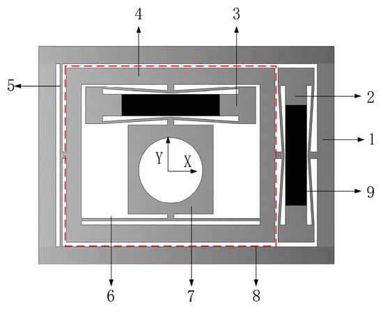
Figure 1.
Structure diagram of micro-positioning platform.
2.1. Working Principle of Micro-Positioning Platform
As can be seen from the structure diagram of the micro-positioning platform, the inner layer portion of the micro-positioning platform moves in the Y direction, while the outer layer portion moves in the X direction. The working principle of the two-direction movement of the micro-positioning platform X and Y is the same. Taking the X-direction movement of the micro-positioning platform as an example, the working principle of the micro-positioning platform is introduced, as shown in Figure 2.
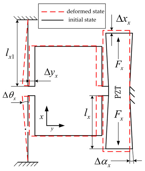
Figure 2.
The working principle diagram of micro-platform in the X direction.
The piezoelectric actuator is vertically elongated after the voltage is applied, and the two inner bumps of the hourglass displacement amplification mechanism are subjected to the driving force of the piezoelectric actuator, and the hourglass elastic plate hinge generates a swing angle of . The elastic plate is elastically deformed, resulting in displacement deformation and angular deformation, effective amplification the piezoelectric actuator output displacement , and pulling the inner substrate to realize the X-direction movement in combination with the guiding function of the transfer mechanism of displacement, thereby realizing the movement of the micro-positioning platform in the X direction.
2.2. Design and Optimization of Hourglass Displacement Amplification Mechanism
2.2.1. Hourglass Displacement Amplification Mechanism
Through the design and analysis of the hourglass displacement amplification mechanism to effectively amplify the driving volume of piezoelectric actuators. Figure 3 shows an hourglass displacement amplification mechanism, which is mainly composed of inner bump, connector, piezoelectric actuator and elastic plate hinges. The piezoelectric actuator is connected to the inner bump.
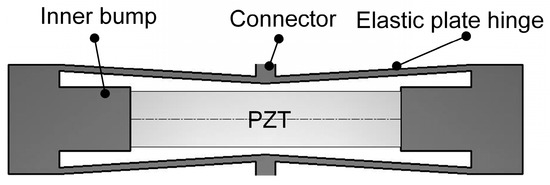
Figure 3.
Hourglass displacement amplification mechanism.
2.2.2. Working Principle of Hourglass Displacement Amplification Mechanism
The working principle of the hourglass displacement amplification mechanism is shown in Figure 4a. Figure 4b is an elastic plate hinge motion model of the hourglass displacement magnification mechanism. The hourglass displacement amplification mechanism provides a certain preloading force for the piezoelectric actuator to be clamped horizontally between the two inner bumps of the amplification mechanism. The bump can increase the stiffness of the hourglass displacement amplification mechanism and reduce the displacement loss. When the piezoelectric actuator inputs the driving amount of to the amplifying mechanism at point A, the driving volume causes the elastic plate hinge to elastically deform and generates turning angle at points A and B, thereby causing the amplified displacement at point B to be generated.

Figure 4.
The schematic of hourglass amplification mechanism. (a) Working principle diagram of hourglass displacement amplification mechanism; (b) Motion model of quarter hourglass amplification mechanism.
2.2.3. Magnification Ratio of Hourglass Displacement Amplification Mechanism
The elastic plate hinge is the core component of the hourglass amplification mechanism and the elastic deformation of the elastic plate hinge provides displacement deformation and angular deformation to amplification mechanism. The elastic plate hinge structure of the hourglass amplification mechanism is composed of flexible plates with length l, width b and thickness t.
The force model of the hourglass displacement amplification mechanism is shown in Figure 5. When the piezoelectric actuator is applied with voltage extension, the two inner bumps of the hourglass are subjected to the force F and the elastic plate hinge undergoes a certain elastic deformation, the amplification mechanism produce displacement in the Y direction.
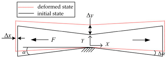
Figure 5.
Force model of hourglass displacement amplification mechanism.
The hourglass displacement amplification mechanism is a symmetrical structure and an elastic plate hinge model can be taken out for force analysis. The force model is shown in Figure 6.
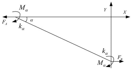
Figure 6.
Force model of hourglass displacement amplification mechanism.
and are the horizontal tensile force of the inner bump and the connector acting on the elastic plate hinge, respectively. According to the principle of force balance,. As shown in Figure 4b, the elastic plate hinge generates turning angle at points A and B during the movement, so that the moment is generated at the hinge A and B. is the rotation stiffness of the elastic plate hinge at points A and B. With the hinge B as the restraining end, the moment of the elastic plate hinge AB is:
where l is the length of the AB elastic plate hinge; is the angle between the elastic plate hinge and the horizontal X-axis; is the rotation angle of the elastic plate hinge; can be expressed as follows:
where E is the elastic modulus of the material. Decompose the horizontal tensile force F at point A into the force along the direction of the elastic plate hinge:
where is the elongation length of the elastic plate hinge, and is the tensile stiffness of the elastic plate hinge. can be expressed as follows:
The point A of the elastic plate hinge produces a displacement of under the action of the horizontal tension force F, and the work done by the horizontal tension force F is:
After substituting Equations (1) and (2) into Equation (3), horizontal displacement can be derived as:
The displacement of point B in the vertical direction is , which can be expressed as:
Therefore, the displacement amplification ratio equation of the hourglass displacement amplification mechanism can be derived as:
2.2.4. Optimization of Structural Parameters of Hourglass Displacement Amplification Mechanism
According to Equation (8), the amplification ratio of the hourglass displacement amplification mechanism is mainly affected by the elastic plate hinge length l, the hourglass hinge tilt angle α, and the hinge thickness t. Reasonable optimization of the three structural parameters of the hourglass displacement amplification mechanism can make the hourglass displacement amplification mechanism have better amplification effect.
The relationship between the elastic plate hinge length l of the hourglass displacement amplification mechanism, the tilt angle α of the elastic plate hinge and the magnification ratio is shown in Figure 7. As can be seen from the Figure, the displacement magnification ratio of the hourglass displacement amplification mechanism increases as the length of the elastic plate hinge increases. With increasing tilt angle of the elastic plate hinge, the magnification ratio decreased after an initial increase. When the angle of the elastic plate hinge is 1°, the displacement magnification of the hourglass displacement amplification mechanism is the largest. When the tilt angle is too small, the output force of the hourglass displacement amplification mechanism will be reduced, so that the overall working stroke of the platform is reduced and the tilt angle is too small will also reduce the stiffness of the hourglass displacement amplification mechanism, so the tilt angle is taken as α = 3.5°. In theory, the length of the elastic plate hinge is as long as possible, However, considering that the overall size of the platform cannot be too large and the stiffness of the hourglass displacement amplification mechanism must be sufficient, the length of the elastic plate hinge is taken as l = 30.5 mm. The thickness t of the flexible hinge is generally 1 mm. If the thickness is too thin, the stiffness of the platform will be insufficient, and if it is too thick, the elastic deformation of the hinge will be reduced, so the thickness t of the elastic plate hinge of the hourglass displacement amplification mechanism is taken as 1 mm. Finally, l = 30.5 mm, α = 3.5°, t = 1 mm and the magnification ratio is 14.9.
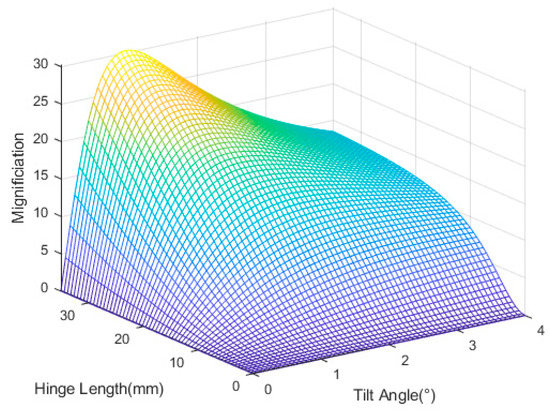
Figure 7.
Effects of hinge length and tilt angle on magnification.
2.3. Static Analysis of Micro-Positioning Platform
According to the knowledge of elastic mechanics and related literature [31], the elastic plate hinge of the hourglass displacement amplification mechanism and the elastic plate transfer mechanism of displacement can be simplified as an elastic plate spring. The elastic plate spring can be equivalent to two antisymmetric cantilever beam models, and the half-beam model method is used to derive the stiffness formula the transfer mechanism of displacement and the stiffness formula of the hourglass displacement amplification mechanism. Therefore, the relationship between the piezoelectric actuator output force F and the output displacement of the micro-positioning platform can be derived:
Among them:
where is the angle between elastic plate hinge of hourglass displacement amplification mechanism and horizontal X-axis; b is the width of elastic plate hinge of hourglass displacement amplification mechanism and transfer mechanism of displacement; t is the thickness of elastic plate hinge of hourglass displacement amplification mechanism and transfer mechanism of displacement; and are respectively the vertical output forces of the X and Y direction piezoelectric actuators for the hourglass displacement amplification mechanism; x and y are respectively the displacement of the stage in the X and Y directions; and are the stiffness of transfer mechanism of displacement in the X and Y directions, respectively; and are the stiffness of the hourglass displacement amplification mechanism in the X and Y directions, respectively; and are 1/2 lengths of transfer mechanism of displacement in the X and Y directions, respectively; and are the lengths of the elastic plate hinges of the hourglass displacement amplification mechanism in the X and Y directions, respectively; E is the elastic modulus of the material.
Bringing the platform size parameters into Equations (11)–(14) can obtain the stiffness of the micro-positioning platform hourglass displacement amplification mechanism, the stiffness of the displacement transmission mechanism, and the overall stiffness of the micro-positioning platform in the X and Y directions, as shown in Table 1. Where: , mm, b = 10 mm, t = 1 mm.

Table 1.
Micro-positioning platform theoretical stiffness table.
In ANSYS/Workbench, 100 N, 200 N and 300 N driving forces were respectively applied to the X and Y directions of the micro-positioning platform for simulation analysis. The force acts on the mounting surface of the piezoelectric actuator and the displacement amplification mechanism, and the direction of the force is the same as the extension direction of the piezoelectric actuator. Figure 8 shows the output displacement on the path of the displacement transmission mechanism under the driving force in the X direction, and Figure 9 shows the output displacement on the path of displacement transmission mechanism under the driving force in the Y direction.
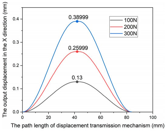
Figure 8.
Relationship between force and displacement curve of micro-platform in the X direction.
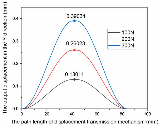
Figure 9.
Relationship between force and displacement curve of micro-platform in the Y direction.
According to Figure 8, Figure 9 and the stiffness calculation formula, the simulation stiffness of the micro-positioning platform in the X and Y directions can be obtained, as shown in Table 2.

Table 2.
Micro-positioning platform simulation stiffness table.
The elastic deformation of the material under different driving forces will slightly change the structure of the platform, resulting in different stiffness under different driving forces. Taking the average of three simulation results, the stiffness of the micro-positioning platform in the X direction is 46,873 N/m and the stiffness in the Y direction is 46,832N/m. The comparison between the theoretical analysis and the simulation analysis of the stiffness of the micro-positioning platform is shown in Table 3.

Table 3.
Comparison of theoretical value and simulation value of micro-positioning platform stiffness.
It can be seen from the table that the theoretical analysis values of the stiffness in the X and Y directions of the micro-positioning platform are only 41 N/m different from the simulation analysis values, which is about 0.08%, thus verifying that the stiffness in the X and Y directions of the micro-positioning platform is equal. The difference between the theoretical stiffness value and the simulated stiffness value is 4.5%, which further verifies the reliability of the theoretical calculation.
In ANSYS/Workbench, 3D solid elements are used to simulate the displacement of the micro-positioning platform in the X and Y directions. Figure 10 is the boundary conditions of the simulation. Under standard earth gravity, the outer substrate of the micro-positioning platform is fixed and the mounting surface BC, DE of the piezoelectric actuator is subjected to an input displacement of 50 μm. Figure 11 shows the mesh division of the micro-positioning platform. The mesh size is set to 1mm and the mesh type is Hex Dominant. The relevance center of mesh is fine and the smoothing of mesh is high. The results are shown in Figure 12 and Figure 13. When the piezoelectric actuator drive volume is up to 50 μm, the maximum working stroke in the X direction of the micro-positioning platform is 498 μm, the displacement magnification is 9.96; the maximum working stroke in the Y direction is 497 μm, and the displacement magnification is 9.94. Thus, the stroke and magnification ratios of the X and Y directions of the micro-positioning platform are also equal.
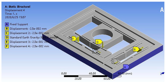
Figure 10.
Boundary conditions for simulation of micro-positioning platform.
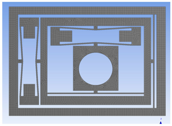
Figure 11.
The mesh of micro-positioning platform.
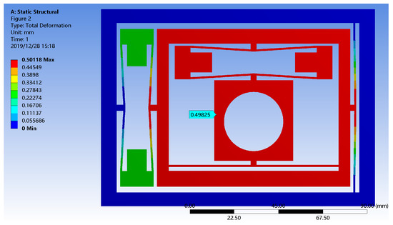
Figure 12.
The displacement simulation of micro-positioning platform in the X direction.
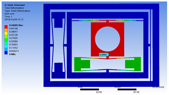
Figure 13.
The displacement simulation of micro-positioning platform in the Y direction.
In order to verify the accuracy of the simulation results, the convergence of the mesh is discussed. Table 4 is the simulation results of the micro-positioning platform in the XY direction under different mesh qualities. It can be seen from Table 4 that the simulation results gradually converge with the improvement of the mesh quality and the number of elements. When the mesh size is 1 mm, the results have converged, so the simulation results are more reliable.

Table 4.
The simulation results of the micro-positioning platform in the XY direction under different mesh qualities.
3. Experimental Analysis
In order to verify the performance of the micro-positioning platform, a micro-positioning platform experimental test system was built, as shown in Figure 14. Figure 15 is a prototype of the micro-positioning platform. The experimental system consists of a micro-positioning platform, Rp150/7 × 7/50 stacked piezoelectric actuator with a maximum driving voltage of 150 V, a displacement of 50 μm at the maximum driving voltage, a drive power, an eddy current sensor, a dSPACE1104 controller and a computer. The controller is dSPACE1104 produced by the dSPACE Ltd. in Paderborn, Germany. The stacked piezoelectric actuator Rp150/7 × 7/50 and the drive power supply RH13 are produced by Harbin Soluble Core Technology Co., Ltd. in Harbin, China. The eddy current sensor is produced by Japan AEC Corp in Kawasaki-City, Kanagawa, Japan, the model is PU-05.
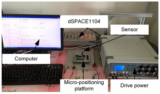
Figure 14.
Measurement experiment system of the micro-positioning platform.
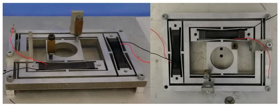
Figure 15.
Measurement experiment system of the micro-positioning platform.
3.1. Micro Positioning Platform Maximum Output Displacement Test
In the micro-positioning platform experimental test system, the piezoelectric actuator has a maximum output displacement of 50 μm at a driving voltage of 150 V. Taking the step voltage of 15 V and applying 0–150 V voltage to the X and Y directions of the micro-positioning platform, respectively. The voltage-displacement curves in the X and Y directions are as shown in Figure 16.
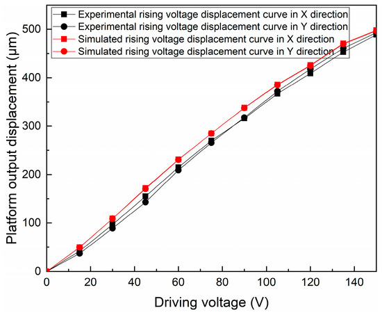
Figure 16.
Relation curve between driving voltage and output displacement in experiment and simulation.
In the voltage range of 0–150 V, the simulated output displacement of the micro-positioning platform is slightly higher than the experimental output displacement, and the overall trend is consistent. According to the experimental test, the maximum output displacement of the micro-positioning platform in the X direction is 489 μm, and the maximum output displacement in the Y direction is 493 μm.
Table 5 shows the comparison of the maximum output displacement of the micro-positioning platform simulation and experiment. It can be seen from the table that the experimental output displacement of the micro-positioning platform in the X/Y direction is basically consistent with the simulated output displacement.

Table 5.
Platform output displacement comparison table.
3.2. Micro-Positioning Platform X/Y Direction Coupling Experiment
At present, a major problem in the 2D micro-positioning platform is that the motion interference and coupling are serious in XY directions. Therefore, it is necessary to carry out experimental tests on the coupling displacement of the micro-positioning platform in X and Y directions. A driving voltage of 0–150 V with a step size of 15 V is applied in the X and Y directions, respectively, and the coupling displacement in the Y and X directions is measured.
Figure 17 and Figure 18 are coupling displacement diagrams in Y and X directions. According to Figure 17 and Figure 18, the maximum coupling ratio in the Y direction is 2.38% and the maximum coupling ratio in the X direction is 2.70% when we applied 15 V driving voltage in the X and Y directions, respectively (Coupling ratio in the Y direction = Coupling displacement in the Y direction/Output displacement in the X direction). The coupling is caused because the displacement amplification mechanism and the elastic plate displacement transmission mechanism of the micro-positioning platform generate machining defects and elastic deformation during the machining process. This can result in coupling displacements in undesired directions. In general, the micro-positioning platform has a low coupling ratio in the X and Y directions.
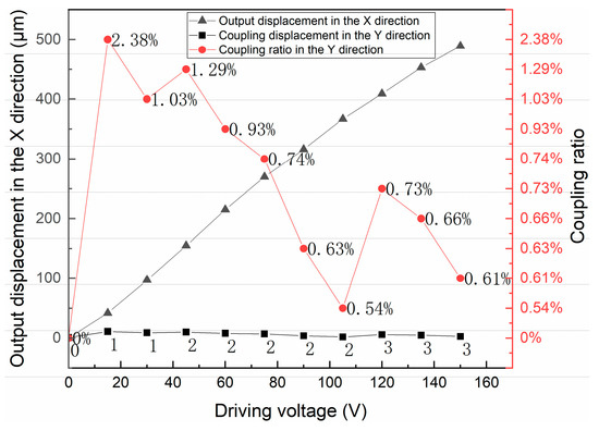
Figure 17.
Y-direction coupling displacement when moving in the X direction of the platform.
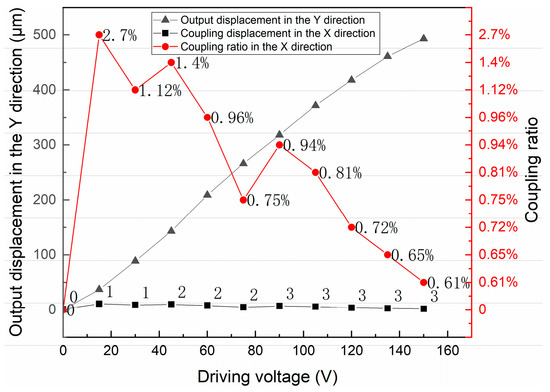
Figure 18.
X-direction coupling displacement when moving in the Y direction of the platform.
4. Conclusions
The hourglass displacement amplification mechanism proposed in this paper can effectively amplify the micro-displacement of the piezoelectric actuator, which is the key to realize the long stroke of the micro-positioning platform. The nested structure of the micro-positioning platform makes the movements in the X and Y directions do not interfere with each other. The design of the micro-positioning platform with equal stiffness in XY direction improves the positioning accuracy and reduces the coupling displacement of the micro-positioning platform. After experimental test, the maximum output displacement of the micro-positioning platform in the X direction is 489 μm, and the maximum output displacement in the Y direction is 493 μm and the maximum coupling rate is 2.7%. The micro-positioning platform achieves the purpose of equal-stiffness, equal- stroke, small size and low coupling. The above studies still have some shortcomings, such as repeated positioning accuracy and the minimum resolution of the micro positioning platform, which will be reported in subsequent studies.
Author Contributions
Conceptualization, F.S., Y.H., F.X. and Q.L.; methodology, F.S., Y.H., M.Z. and J.J.; software, F.S., Y.H., F.X. and Q.L.; validation, F.S., L.T., M.Z. and J.J.; formal analysis, F.S., F.X., M.Z. and J.J.; investigation, F.S., Y.H., F.X. and X.Z.; resources, F.S., X.Z., F.X. and Q.L.; data curation, M.Z., L.T. and Q.L.; writing—original draft preparation, F.S., Y.H., X.Z. and L.T.; writing—review and editing, F.S., Y.H. and F.X.; visualization, F.S., Y.H., F.X. and J.J.; supervision, F.S. and F.X. All authors have read and agreed to the published version of the manuscript.
Funding
This research is supported by LiaoNing Revitalization Talents Program (No. XLYC1802077), Scientific research fund project of Liaoning Provincial Department of Education (No. LJGD2019011).
Conflicts of Interest
The author declares no conflict of interest.
References
- Qu, J.; Chen, W.; Zhang, J.; Chen, W. A large-range compliant micropositioning stage with remote-center-of-motion characteristic for parallel alignment. Microsyst. Technol. 2015, 22, 777–789. [Google Scholar] [CrossRef]
- Sun, X.; Chen, W.; Fatikow, S.; Tian, Y.; Zhou, R.; Zhang, J.; Mikczinski, M. A novel piezo-driven microgripper with a large jaw displacement. Microsyst. Technol. 2014, 21, 931–942. [Google Scholar] [CrossRef]
- Lee, H.-J.; Woo, S.; Park, J.; Jeong, J.-H.; Kim, M.; Ryu, J.; Gweon, D.-G.; Choi, Y.-M. Compact compliant parallel XY nano-positioning stage with high dynamic performance, small crosstalk, and small yaw motion. Microsyst. Technol. 2017, 24, 2653–2662. [Google Scholar] [CrossRef]
- Chen, W.; Qu, J.; Chen, W.; Zhang, J. A compliant dual-axis gripper with integrated position and force sensing. Mechatronics 2017, 47, 105–115. [Google Scholar] [CrossRef]
- Liao, C.; Xu, M.; Xiao, R.; Han, W. Integrated design of piezo-actuated 2-DOF submillimeter-range super-resolution platform with self-sensing unit. Mech. Syst. Signal Process. 2020, 139. [Google Scholar] [CrossRef]
- Lai, L.-J.; Zhu, Z.-N. Design, modeling and testing of a novel flexure-based displacement amplification mechanism. Sens. Actuators A Phys. 2017, 266, 122–129. [Google Scholar] [CrossRef]
- Sun, X.; Yang, B. A new methodology for developing flexure-hinged displacement amplifiers with micro-vibration suppression for a giant magnetostrictive micro drive system. Sens. Actuators A Phys. 2017, 263, 30–43. [Google Scholar] [CrossRef]
- Tang, H.; Chen, C.; Li, Y.; Gao, J.; Chen, X.; Yu, K.-M.; To, S.; He, Y.; Chen, X.; Zeng, Z.; et al. Development and Repetitive-Compensated PID Control of a Nanopositioning Stage With Large-Stroke and Decoupling Property. IEEE Trans. Ind. Electron. 2018, 65, 3995–4005. [Google Scholar] [CrossRef]
- Lin, C.; Shen, Z.; Wu, Z.; Yu, J. Kinematic characteristic analysis of a micro-/nano positioning stage based on bridge-type amplifier. Sens. Actuators A Phys. 2018, 271, 230–242. [Google Scholar] [CrossRef]
- Xing, H.; Zhang, T.-M.; Yang, X.-L.; Zhang, J.-T.; Qi, H.-X. Advances in large-stroke and high-resolution drive system. Mech. Sci. Technol. Aerosp. Eng. 2013, 32, 888–894. [Google Scholar]
- Muraoka, M.; Sanada, S. Displacement amplifier for piezoelectric actuator based on honeycomb link mechanism. Sens. Actuators A Phys. 2010, 157, 84–90. [Google Scholar] [CrossRef]
- Liu, X.-R.; Huang, W.-Q.; Wang, Y. A novel 2Dpiezo-nanopositioning stage based on triangle amplifier mechanism. In Proceedings of the 2016 Symposium on Piezoelectricity, Acoustic Waves, and Device Applications IEEE, Xian, China, 21–24 October 2016. [Google Scholar]
- Liu, D.-Q.; Huang, Y.-M.; Xie, L.; Yang, Y. Positioning control of piezoelectric macro-micro dual drive. Trans. Chin. Soc. Agric. Mach. 2011, 42, 220–223. [Google Scholar]
- Zhang, L.; Long, Z.; Cai, J.; Fang, J. Design of a linear macro–micro actuation stage considering vibration isolation. Adv. Mech. Eng. 2015, 7. [Google Scholar] [CrossRef]
- Zhang, L.; Yang, L.; Sun, L.; Zhang, X. Adaptive Kalman filter and dynamic recurrent neural networks-based control design of macro-micro manipulator. J. Control. Theory Appl. 2012, 10, 504–510. [Google Scholar] [CrossRef]
- Liu, J.-Z.; Zhang, W.-W.; Chen, L.-G.; Pan, M.-Q.; Wang, Y.-J. Vibration Error Compensation in X-Y Direction for High Precision Positioning Platform. J. Vib. Meas. Diagn. 2017, 37, 1227–1232. [Google Scholar]
- Yu, Y.-M.; Leng, J.-S. Design and Dynamic Performances Simulation of a Flexible Micro- displacement Amplification Mechanism. Mach. Des. Res. 2011, 27, 48–51, 55. [Google Scholar]
- Wei, D.; Ruochong, S.; Pengfei, S.; Du, Z.-J.; Sun, L.-N. Development of a piezo-actuated high-precision flexible parallel mechanism. In Proceedings of the 2013 International Conference on Manipulation, Manufacturing and Measurement on the Nanoscale, Suzhou, China, 26–30 August 2013. [Google Scholar]
- Products Home-Electric Displacement Stage. Available online: https://www.thorlabschina.cn/navigation.cfm?guide_id=2060 (accessed on 15 June 2020).
- Nabawy, M.R.A.; Crowther, W.J. Dynamic Electromechanical Coupling of Piezoelectric Bending Actuators. Micromachines 2016, 7, 12. [Google Scholar] [CrossRef]
- Zhang, S.; Liu, J.; Deng, J.; Liu, Y. Development of a Novel Two-DOF Pointing Mechanism Using a Bending–Bending Hybrid Piezoelectric Actuator. IEEE Trans. Ind. Electron. 2019, 66, 7861–7872. [Google Scholar] [CrossRef]
- Dharmawan, A.G.; Hariri, H.H.; Foong, S.; Soh, G.S.; Wood, K.L. Steerable miniature legged robot driven by a single piezoelectric bending unimorph actuator. In Proceedings of the 2017 IEEE International Conference on Robotics and Automation (ICRA), Singapore, 29 May–3 June 2017. [Google Scholar]
- El-Sayed, A.; Abo-Ismail, A.; El-Melegy, M.; Hamzaid, N.; Osman, N. Development of a Micro-Gripper Using Piezoelectric Bimorphs. Sensors 2013, 13, 5826–5840. [Google Scholar] [CrossRef]
- Dong, W.; Chen, F.; Gao, F.; Yang, M.; Sun, L.; Du, Z.; Tang, J.; Zhang, D. Development and analysis of a bridge-lever-type displacement amplifier based on hybrid flexure hinges. Precis. Eng. 2018, 54, 171–181. [Google Scholar] [CrossRef]
- Yang, Z.; He, Z.; Li, D.; Xue, G.; Cui, X. Hydraulic amplifier design and its application to direct drive valve based on magnetostrictive actuator. Sens. Actuators A Phys. 2014, 216, 52–63. [Google Scholar] [CrossRef]
- Choi, K.-B.; Lee, J.J.; Hata, S. A piezo-driven compliant stage with double mechanical amplification mechanisms arranged in parallel. Sens. Actuators A Phys. 2010, 161, 173–181. [Google Scholar] [CrossRef]
- Wu, Z.; Xu, Q. Design, Fabrication, and Testing of a New Compact Piezo-Driven Flexure Stage for Vertical Micro/Nanopositioning. IEEE Trans. Autom. Sci. Eng. 2019, 16, 908–918. [Google Scholar] [CrossRef]
- Chen, J.; Zhang, C.; Xu, M.; Zi, Y.; Zhang, X. Rhombic micro-displacement amplifier for piezoelectric actuator and its linear and hybrid model. Mech. Syst. Signal Process. 2015, 50–51, 580–593. [Google Scholar] [CrossRef]
- Liang, C.; Wang, F.; Huo, Z.; Shi, B.; Tian, Y.; Zhao, X.; Zhang, D. A 2-DOF Monolithic Compliant Rotation Platform Driven by Piezoelectric Actuators. IEEE Trans. Ind. Electron. 2020, 67, 6963–6974. [Google Scholar] [CrossRef]
- Ling, M.; Cao, J.; Jiang, Z.; Zeng, M.; Li, Q. Optimal design of a piezo-actuated 2-DOF millimeter-range monolithic flexure mechanism with a pseudo-static model. Mech. Syst. Signal Process. 2019, 115, 120–131. [Google Scholar] [CrossRef]
- Du, Z.-Y.; Yan, P. Analysis on Compliant Micro Positioning Stage Based on Bridge-type Amplification Mechanism. Robot 2016, 38, 180–191. [Google Scholar]
© 2020 by the authors. Licensee MDPI, Basel, Switzerland. This article is an open access article distributed under the terms and conditions of the Creative Commons Attribution (CC BY) license (http://creativecommons.org/licenses/by/4.0/).