Article

Research on an Electromagnetic Actuator for Vibration Suppression and Energy Regeneration

1
School of Mechanical Engineering, Shenyang University of Technology, Shenyang 110870, China
2
Department of Mechanical Engineering, Nippon Institute of Technology, Saitama 345-8501, Japan
*
Author to whom correspondence should be addressed.
Actuators 2020, 9(2), 42; https://doi.org/10.3390/act9020042
Submission received: 14 April 2020 / Revised: 7 May 2020 / Accepted: 20 May 2020 / Published: 22 May 2020
(This article belongs to the Section Actuators for Manufacturing Systems)

Abstract

:
This paper proposes an electromagnetic actuator that concurrently realizes two working functions of vibration suppression and energy regeneration. The actuator consists of four permanent magnetic rings, three soft iron rings, three coils, and three springs. The design of the electromagnetic actuator is based on finite element method (FEM) analysis, and the prototype is based on this analysis. Based on the prototype, the characteristics of the electromagnetic actuator, which has an output force–current coefficient of 39.49 N/A, are explored. A control algorithm with a position controller and an acceleration controller are applied to the actuator. When an impulse excitation is input to the electromagnetic actuator, the acceleration of the controlled object decreases from 114.26 m/s2 to 3.14 m/s2 here. Moreover, when the sinusoidal excitation with a 3 mm amplitude and 5 Hz frequency is input to the electromagnetic actuator, the vibration amplitude of the controlled object is 0.045 mm, suppressed within 1.46% when compared with the input signal. The peak value of the regenerated electromotive force is 1.97 V here, and the actuator efficiency for regenerating energy is 11.59%. The experimental results with multiple frequencies and amplitudes also show that the amplitude of the controlled object can be suppressed within 5.5%, and that the ratio of the electromotive force (EMF) to the input amplitude is 0.13. The results indicate that this electromagnetic actuator can suppress vibrations effectively and regenerate energy from vibrations.

1. Introduction

Vibration is a common phenomenon of a mechanical system [1] that possesses properties which partly affect the stability and safety of equipment and machine operation. Examples of these mechanical systems include vehicles [2,3], motors [4], elevators, robots [5], construction machinery [6], wind power systems [7], flywheel systems, rail transportation, and many other mechanisms in other fields [8]. Excessive or unwanted vibration may also have a negative effect on the mechanism. For mitigating vibrations of mechanisms, Xu et al. [9] proposed a new vibration isolation and mitigation device which is used to restrain platform vibration under a wide frequency excitation. Le et al. [10] proposed a vibration isolation system which improves the vibration isolation validity of a driver seat. Wu et al. [11] presented a magnetic levitation (maglev) vibration isolation system, and verified the nonlinear dynamic model and the isolation performance, which was proven to be highly effective. Moradi et al. [12] proposed a tunable vibration absorber to suppress regenerative chatter in the milling of cantilever plates, based on the mode summation approach. Rosbi et al. [13] proposed an optimally designed dynamic absorber, using the suppression method of the nonlinear vibration to suppress the occurrence of subharmonic vibration in the natural frequency and the damping ratio. Stelzer et al. [14] developed a semi-active magnetorheological isolator with a low cost that can be used to mount components that generate vibrations. The isolator is applicable for automobiles, engine mounts, pumps, and the isolation of aviation and naval components. Yang et al. [15] studied the vibration power flow and force transmission characteristics of a 2-degree of freedom (DOF) nonlinear system to test the performance of a nonlinear isolator. Wang et al. [16] proposed a two-stage quasi-zero stiffness vibration isolation system, with a low roll-off rate in the effective frequency range of vibration isolation. Therefore, vibration is one of the important factors in machining accuracy, machine operation, and machine life, where reducing vibrations is beneficial with regards to improving machining accuracy and reducing the risk of hidden dangers.
In addition to changing the mechanical structure to alleviate vibrations, vibrations can also be reduced by designing control and theoretical methods that are suitable for the vibration system. Zhang et al. [17] proposed a hybrid error criterion-based frequency-domain least mean square (LMS) control method, for suppressing the vibrations of milling processes using piezoelectric actuators and sensors, which is an effective and reliable way to suppress vibrations and improve the machining quality, based on the simulation and experimental results. Lou et al. [18] proposed a novel optimal trajectory planning approach applied to a flexible piezoelectric manipulator system, which is a combination of this approach and the feedback control of piezoelectric actuators. Zhou et al. [19] proposed an adaptive vibration control method using a pair of mirror finite impulse response filters, to reduce the amplitude of the rear gap vibration and improve the stability and ride comfort of a maglev train. Kotake et al. [20] proposed a vibration manipulation function, applied in a one-dimensional overhead traveling crane to remove the residual vibrations of a hoisted load, and validated the abilities of the proposed function in the crane operation by simulations and experiments. Shao et al. [21] proposed a fault-tolerant fuzzy H∞ control design approach for the presence of sprung mass variations, actuator faults, and control input constraints, to suppress the vibrations of the active suspension of in-wheel motor-driven electric vehicles.
The other fundamental flaw associated with mechanisms is that they expel undesired kinetic energy as heat, meanwhile, energy loss generated by vibrations is also a hot topic of current research. Ze et al. [22] proposed a new capacitive energy recycling converter to improve the power generation performance of a doubly salient permanent magnet generator. Warner et al. [23] proposed three actuator models considered for energy regeneration potential of the knee joint. Manna et al. [24] designed a novel energy-harvesting device, using magnetic levitation to produce an oscillator with a tunable resonance, and investigated the energy-harvesting potential of this prototypical nonlinear system. Elvin et al. [25] presented an experimentally validated electromagnetic energy harvester, the results of which show a normalized power density of 1.7 mW/[(m/s2)2 cm3] when operating at a resonance frequency of 112.25 Hz. Glynne-Jones et al. [26] described miniaturized generators for converting ambient vibration energy into electrical energy, as applied in powering intelligent sensors. These generators have been tested with a vehicle engine and have produced a peak power of 3.9 mW with an average power of 157 W. Xu et al. [27] put forward a braking system using only electric motors/generators as the actuators, the generated energy of which can be fed back to the onboard energy storage system as much as possible. Zhang et al. [28] proposed an energy-efficient torque allocation scheme to increase traction efficiency and brake energy-recovery. Yan et al. [29] put forward an energy regeneration implementation scheme to achieve an energy-saving goal of active suspension with self-power supply potential in a practical application.
To obtain energy from vibrations, energy regenerating mechanisms have been generally divided into three main categories, namely, rotation energy regeneration mechanisms, linear energy regeneration mechanisms, and energy regeneration mechanisms based on energy regenerating materials [30]. Rotation energy regeneration mechanisms convert reciprocating linear vibrations into bidirectional rotary motion to produce electricity [31]. Liu et al. [32] proposed an energy-harvesting shock absorber based on a mechanical motion rectifier, which is able to harvest an average power of 13.3 W for a representative period of 8 s on a paved road at 40 mph. Linear energy regeneration mechanisms adopt a coil, or multiple coils, to cut the magnetic flux to generate electric energy and produce a back electromotive force [33,34]. Buren et al. [35] presented a prototype linear electromagnetic generator that supplied power to body-worn sensor nodes with an output power of 2–25 W while walking. Arroyo et al. [36] presented and optimized a new electromagnetic harvester with a nonlinear energy extraction circuit (the synchronized magnetic flux extraction technique), the experimental results of which show that a rectified power of 1.6 mW is harvested at 1g excitation acceleration at 100 Hz frequency over a 10 Hz bandwidth. Tang et al. [37] presented a tubular linear electromagnetic transducer, applied in large-scale vibration energy-harvesting from vehicle suspensions, tall buildings, or long-span bridges. The experiment results show that the prototype (63.5 mm outer diameter, 305 mm compressed length) can harvest 2.8 W of power under a 0.11 m/s relative velocity, with a damping coefficient of 940 N·s/m. Sapiński [38] proposed an energy-harvesting linear magnetorheological (EH-LMR) damper to obtain energy from external excitations, using an electromagnetic energy extractor with self-powered and self-sensing capabilities. The energy regenerating mechanism uses the characteristics of energy regenerating materials to regenerate energy [39]. Liu et al. [40] designed, microfabricated, and characterized a piezoelectric microelectromechanical systems (MEMS) energy-harvester which has a wideband and steadily increased power from 19.4 nW to 51.3 nW within the operating frequency bandwidth of 30–47 Hz at gravity acceleration of 1.0 g. Liu et al. [41] studied a cantilevered energy-harvesting device, with a root mean square (RMS) harvesting power up to 13.3 mW and a RMS power density of up to 3.7 mW/cm3/g, based on an iron–gallium alloy magnetostrictive material for low frequencies, verifying the electricity-generating capability of the harvester prototype. The energy generated by vibrations can be collected by the energy regenerating mechanisms mentioned above, and stored in a battery through a series of energy regenerating circuits. Because the linear energy regeneration mechanism has the advantages of high efficiency, non-contact, no lubrication, and being non-pollutive, this scheme was adopted for energy regeneration in this study.
This paper presents a novel electromagnetic actuator, that has been designed to produce energy via vibrations while suppressing said vibrations, which can be installed in many kinds of mechanisms to improve machining accuracy and reduce energy loss. Firstly, the electromagnetic actuator is proposed, and the vibration suppression function and energy regeneration function are explained in detail. Then, the proposed electromagnetic actuator is designed based on the static magnetic field simulation with finite element method (FEM) analysis, and its prototype is fabricated. Based on this prototype, characteristics of the electromagnetic actuator are explored via measuring experiments. Furthermore, a control algorithm with a position controller and an acceleration controller is applied to the proposed actuator. Finally, an experimental control system is built, and experiments of the impulse and sinusoidal excitation responses are carried out to verify the feasibility and effect of the electromagnetic actuator.

2. Structure and Working Functions

2.1. Structure

As shown in Figure 1, the electromagnetic actuator consists of a controlled object, three coils, four permanent magnet rings (PM rings), four soft iron rings, a soft iron outer shell, three springs, an acceleration sensor (acc. sensor), and a displacement sensor (disp. sensor). Three springs are used to support the controlled object and three coils are fixed on the controlled object. The soft iron outer shell, three springs, and four PM rings are fixed on a stator. The axial-magnetized PM rings are adopted here to generate a concentrated magnetic flux in the surrounding air gap, and the arrangement of the PM rings is shown in Figure 1.
The coils are facing the soft iron rings to cut as much magnetic flux as possible. Here, coil2 is used for suppressing vibration, and coil1 and coil3 are used for synchronously regenerating energy. The acc. sensor and the disp. sensor are used to measure the acceleration and the displacement of the controlled object, respectively.

2.2. Working Functions

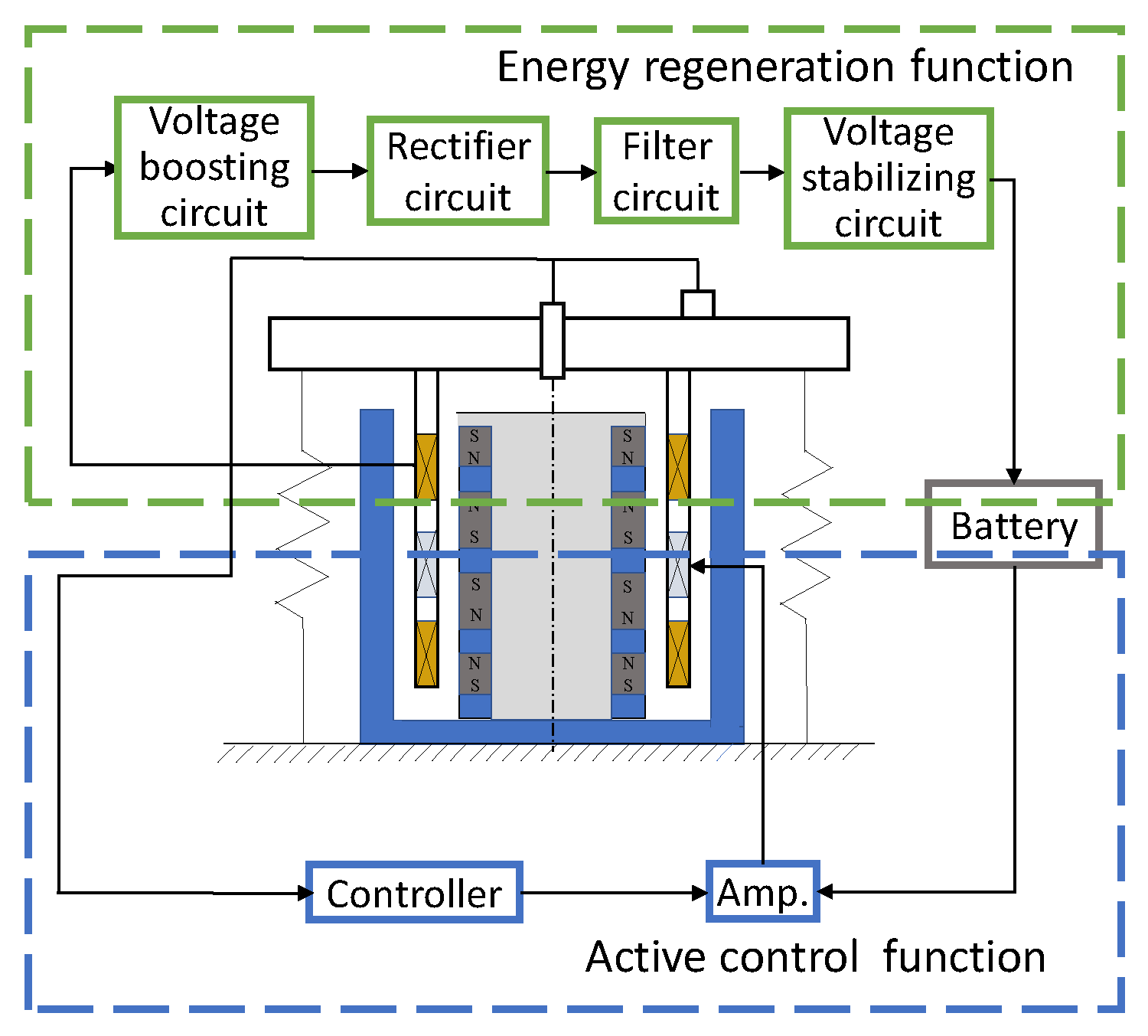
As shown in Figure 2, the proposed electromagnetic actuator has a vibration suppression function and energy regeneration function, which are used at the same time during vibration.
The vibration suppression function is used to decrease useless vibrations of the controlled object. The disp. sensor and acc. sensor measure the displacement and acceleration of the controlled object, respectively, which is fed back to a controller, where the amplified control current is applied to coil2 and the electromagnetic actuator can generate an output force for suppressing vibrations of the controlled object.
The energy regeneration function collects the kinetic energy from vibrations of the controlled object. Because of the relative motion between the controlled object and the PM rings, coil1 and coil3 cut magnet flux in the air gap of the electromagnetic actuator. An electromotive force (EMF) can be produced and stored in the battery by a series of circuits, such as a voltage boosting circuit, rectifier circuit, filter circuit, and voltage stabilizing circuit.

3. Design and Fabrication of the Electromagnetic Actuator

3.1. Design of the Electromagnetic Actuator

For the electromagnetic actuator, it is necessary to realize a compact size and a large output force. The output force of the electromagnetic actuator is mainly affected by the PM rings, coil2, and soft iron ring1. The PM rings were not made according to demand and use products from a magnetic materials company (NeoMag Co., Ltd.). In the design of the PM rings, their selection requirements were that the inner and outer diameters are the same. Four PM rings are magnetized along the axis direction and placed to face the same magnetic poles.
Meanwhile, the height and thickness of coil2 and the height of soft iron ring1 affect the output of the proposed actuator. Here, an orthogonal experiment method is used to analyze the influences of the height and thickness of coil2 and the height of soft iron ring1 on the output force of the proposed actuator. The height and thickness of coil2 and the height of soft iron ring1 are determined as three factors of the orthogonal experiment method, and each factor has three levels, as shown in Table 1. In the simulations of the output force, coil2 has a 0.5 mm diameter arranged in a single turn. The coil2 current is calculated according to the maximum current of section 10 A/mm2. The coercivity of the PM rings is 868 KA/m and the residual flux density of the PM rings is 1.17 T. The magnetic permeability of the soft iron rings is 1.17 T. Assuming that any two factors cannot interact with each other, size optimization simulations of the actuator based on the FEM analysis by orthogonal experiment method were carried out to find the optimal combination of the maximum output force of the electromagnetic actuator, as listed in Table 2.
The analysis by the orthogonal experiment method is shown in Table 3. Kjk (k = 1, 2, 3) is the sum of the simulation results with the same level k in the jth column. Kjpk is the mean value of the simulation results with the same level k in the jth column. Rj is the range of Kjpk. As can be observed, the combination (A3B3C2) constitutes the optimal parameters, which are the height of coil2 (40 mm), the thickness of coil2 (8 mm), and the height of soft iron ring1 (10 mm), and the output force is 72.78 N.
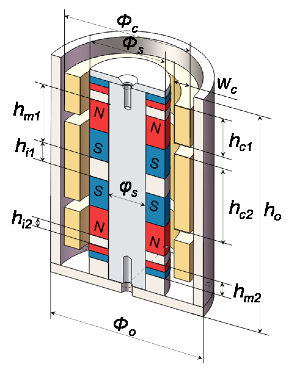
The heights of PM ring2 and soft iron ring2 are smaller than that of PM ring1 and soft iron ring1, due to the overall sizes. The soft iron outer shell is split into two parts due to the simple assembly of the PM rings and soft iron rings. It must be noted that the safe distance between the coils and the soft iron shell must be ensured, and friction between the coils and other parts is avoided. The optimized configuration of the electromagnetic actuator is shown in Figure 3 and its main parameters are listed in Table 4.
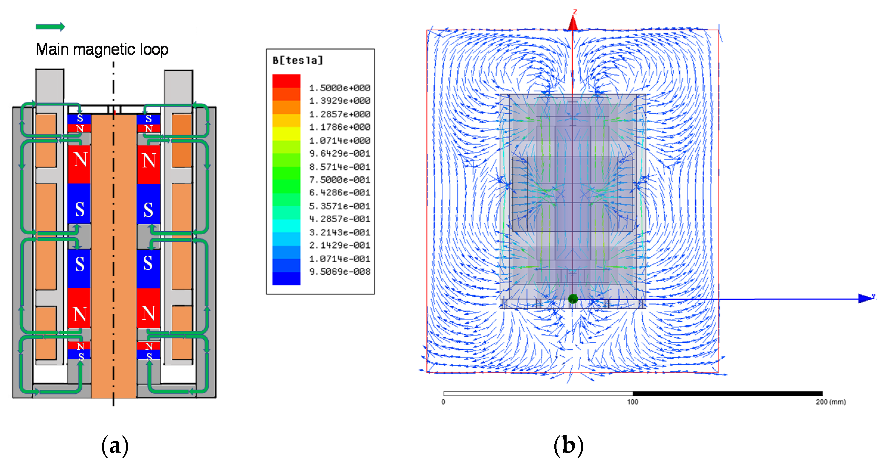
The magnetic flux distribution was explored in order to design the electromagnetic actuator, as shown in Figure 4. The magnetic flux of the PM rings starts from the N pole and returns to the S pole, passing through the soft iron rings, air gap, coils, and soft iron outer shell.
Magnetic loops are shown in Figure 4a. The magnetic flux distribution was found by magnetic field analysis of FEM, as shown in Figure 4b, where the magnetic flux density in PM ring1 is the largest, namely, about 1.2 T. The coils are facing the soft iron rings and the average value of the magnetic flux density in the air gap is about 0.3 T. It must be ensured that the magnetic flux of the soft iron materials is in an unsaturated state. The magnetic flux density of coil2 is proportional to the output force of the electromagnetic actuator, therefore, the magnetic flux density in the air gap is one of the important factors that determines the overall performance of the electromagnetic actuator.
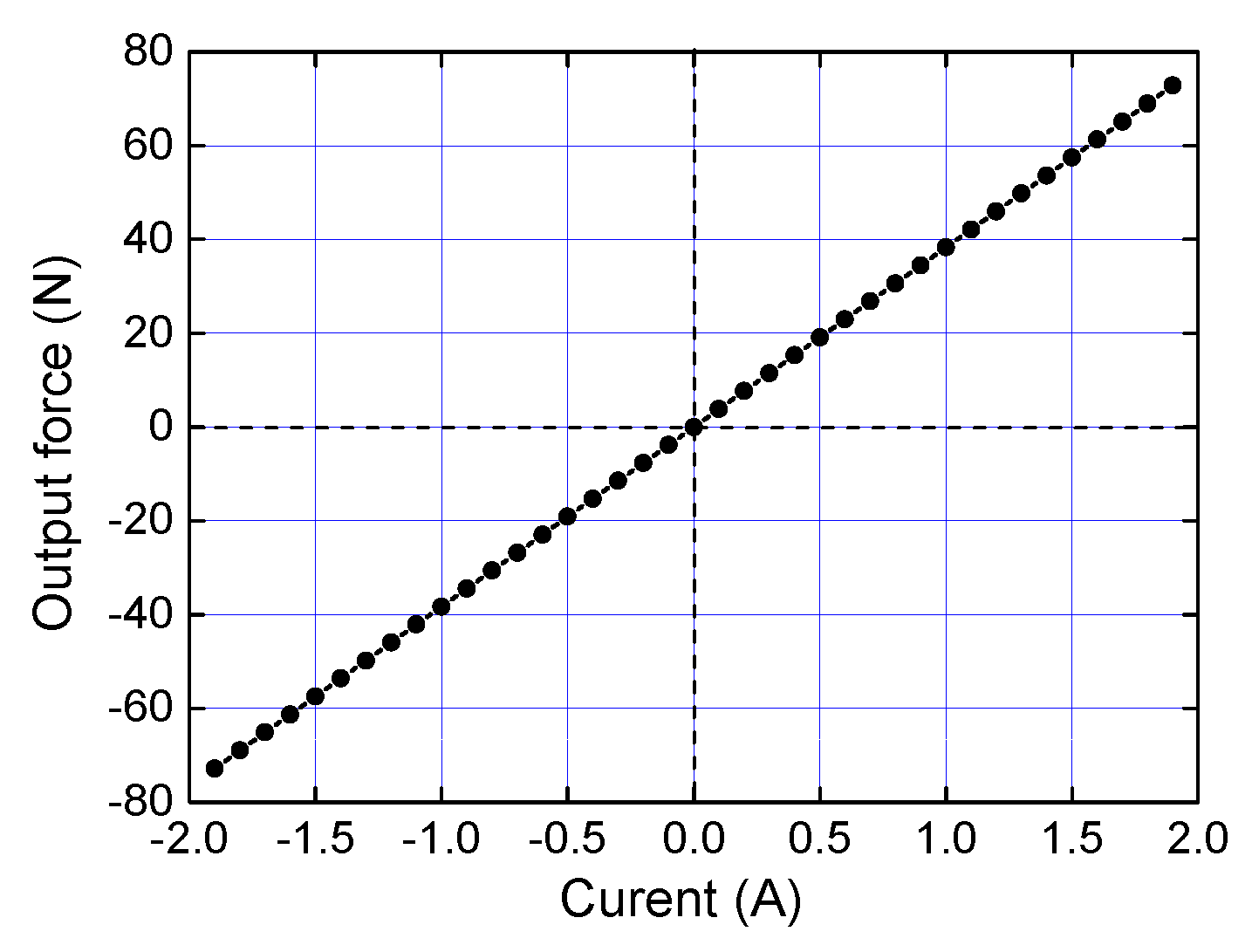
In Figure 5, the relationship between the output force and the coil2 current of the electromagnetic actuator has been simulated by Ansys and Maxwell. Here, coil2 adopts a single-turn enameled wire with a 0.5 mm diameter, and its number of turns is 1280. The coil2 current is applied between −1.9 A and 1.9 A with an interval of 0.1 A to ensure the normal operation of the coil. The output force range of the electromagnetic actuator is approximately −72.78 N to 72.56 N. The simulation result shows that the output force–current relationship has high linearity and that its output force–current coefficient is 38.3 N/A.

3.2. Fabrication of the Prototype

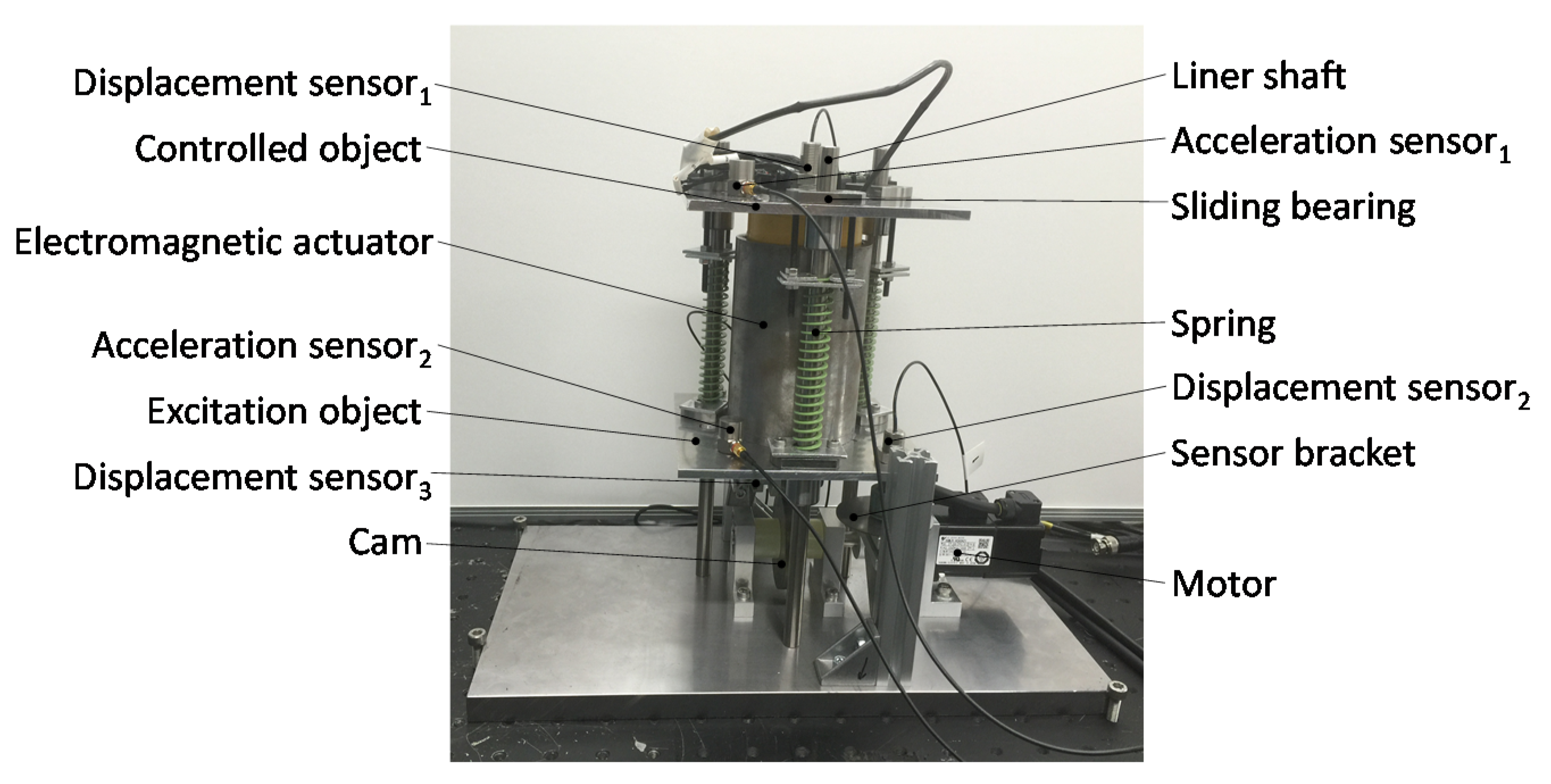
The prototype of the electromagnetic actuator has been fabricated, as shown in Figure 6. An excitation device consists of a cam and a motor, which has been adopted to generate a sinusoidal excitation signal to the actuator. The amplitude and frequency of the sinusoidal excitation can be changed by replacing the various cams and adjusting the motor (SGMJV-A5A3A21, Yaskawa Electric Corp., Kitakyushu, Japan) speed.
The electromagnetic actuator is mounted on the excitation device. An eddy current displacement sensor (eddy current displacement sensor1) (PU-20, AEC Corp., Carrollton, TX, USA) and acceleration sensor (acceleration sensor1) (TYPE 7820A, Aco co.,LTD, Tokyo, Japan) are fixed on the controlled object for measuring its displacement and acceleration. Eddy current displacement sensor2, displacement sensor3 (PU-20, AEC Corp.) and acceleration sensor2 (TYPE 7820A, Aco co.,LTD) are installed on the excitation device for measuring its displacements and acceleration. Liner shafts and sliding bearings play a role of guidance here. The PM rings are made of Nd2Fe14B. The three coils are single-turn enameled wires with a 0.5 mm diameter, which have 612, 1262, and 617 turns, respectively. The controlled object weights 1.37 kg, with overall dimensions of Φ78 × 146 mm, and the mass without the excitation device is 5.01 kg, where the overall dimensions are about 140 mm × 140 mm × 173 mm.

3.3. Characteristics of the Electromagnetic Actuator

The characteristics of the electromagnetic actuator determine its overall performance, and therefore, this section mainly studies and analyzes the electromagnetic actuator from the characteristics of the magnetic flux density and the output force. There are two experiments to measure and analyze these two characteristics of the electromagnetic actuator.
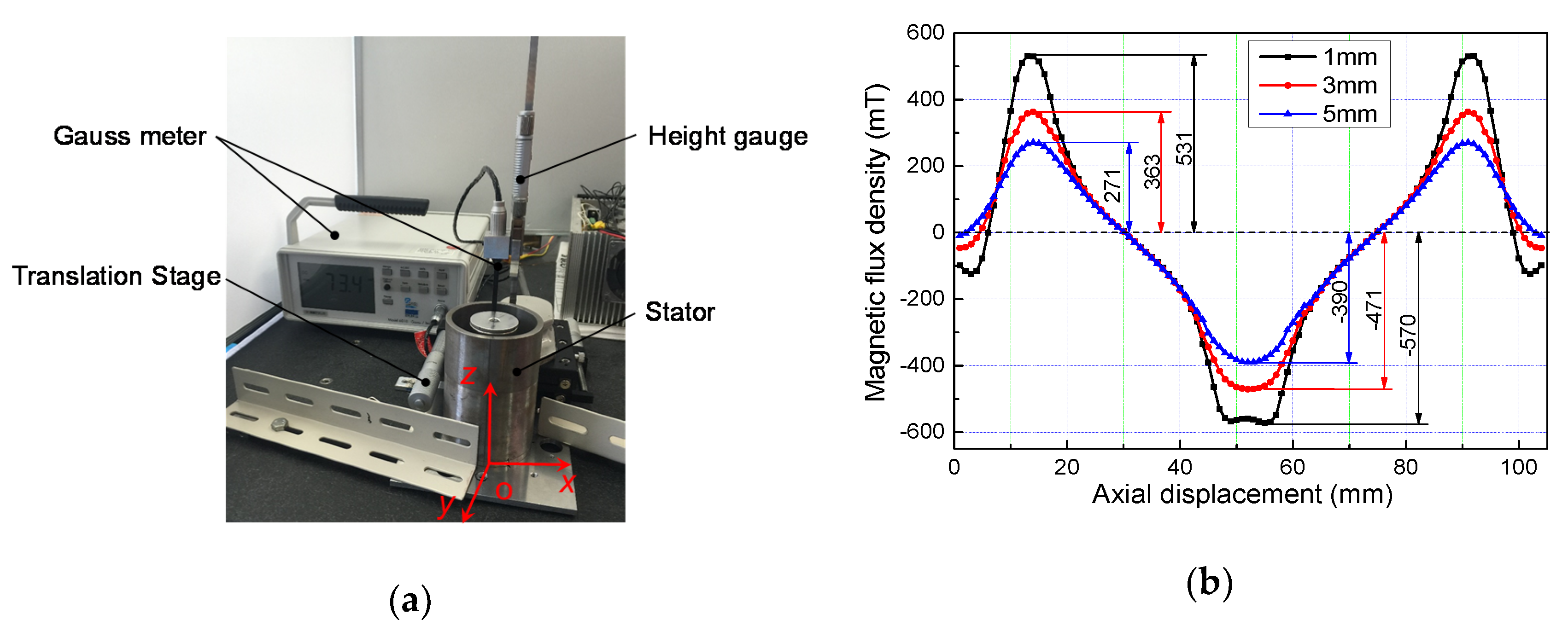
Experimental devices for measuring the magnetic flux density are shown in Figure 7a, composed of a gauss meter (Model 6010, Toyo Corp., Kariya-shi, Japan), height gauge, translation stage, and stator of the electromagnetic actuator. The stator and translation stage are fixed on a workbench, and the height gauge is fixed on the translation stage. The gauss meter’s head is moved along the z-axis by the height gauge and the translation stage is used for movement along the y-axis. The axial range for measuring the magnetic flux density is from 0 to 104 mm, with an increment of 1 mm in the z-axis, and the radial positions for measuring the magnetic flux density are 1 mm, 3 mm, and 5 mm from the outer diameter of the PM rings. The length of the gauss meter’s head is 60 mm and less than the height of the air gap; therefore, the magnetic flux density of the whole air gap is obtained based on the positional symmetry of the PM rings and soft iron rings.
The results for measuring the magnetic flux density are shown in Figure 7b. The maximum values of the N pole are located at axial displacements of 13 mm and 93 mm, and the minimum value of the S pole is at the axial displacement of 53 mm. The values of the magnetic flux density in radial displacements of 1 mm, 3 mm, and 5 mm at axial displacements of 13 mm were 531 mT, 363 mT, and 271 mT, respectively, which are the same as the ones at an axial displacement of 93 mm. The values of the magnetic flux density at radial displacements of 1 mm, 3 mm, and 5 mm at an axial displacement of 53 mm were −570 mT, −471 mT, and −390 mT, respectively. The magnetic flux densities of all curves did not change when the axial displacement changed from 22 mm to 42 mm, and from 64 mm to 84 mm. The experimental results show that the magnetic flux densities at the soft iron rings are relatively at their maximum.
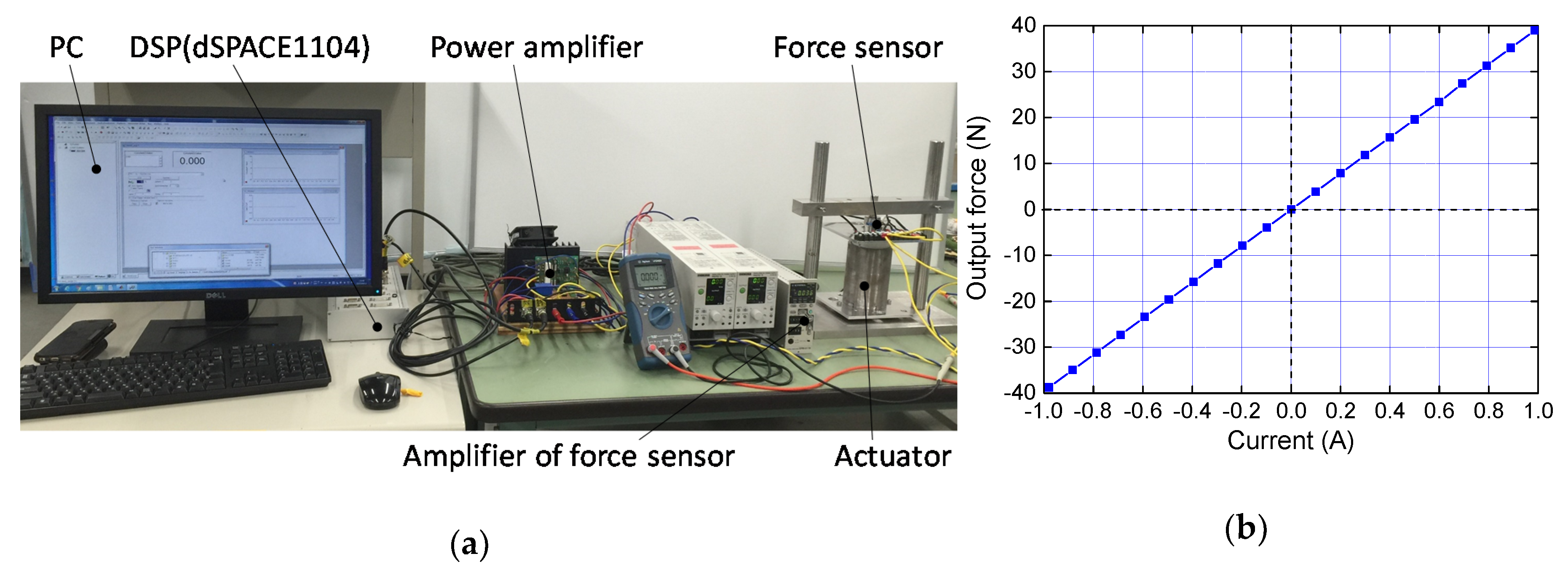
The experimental devices for measuring the output force are shown in Figure 8a. The devices consist of a PC with a digital signal processor (DSP (DS1104, dSPACE Corp., Wixom, MI, USA)) board, a power amplifier, a force sensor, an amplifier of the force sensor, and the proposed actuator. The force sensor (LUR-A-100NSA1, Japan KYOWA Corp., Osaka, Japan) was connected to the controlled object, which was fixed on a bench supported two pillars. A signal generated by the DSP was amplified and applied to coil2. The output force values were recorded on the amplifier of the force sensor. The coil2 current was changed from −1 A to 1 A, with an increment of 0.1 A.
The results for measuring the output force are shown in Figure 8b. It can be seen that the relationship between the output force and the coil2 current is linear, and the output force–current coefficient is 39.49 N/A, which shows that the output force can be easily controlled by inputting the coil2 current. The error between the experiment results and the simulation results is within 3.0%.

4. Control System

4.1. Dynamics Model

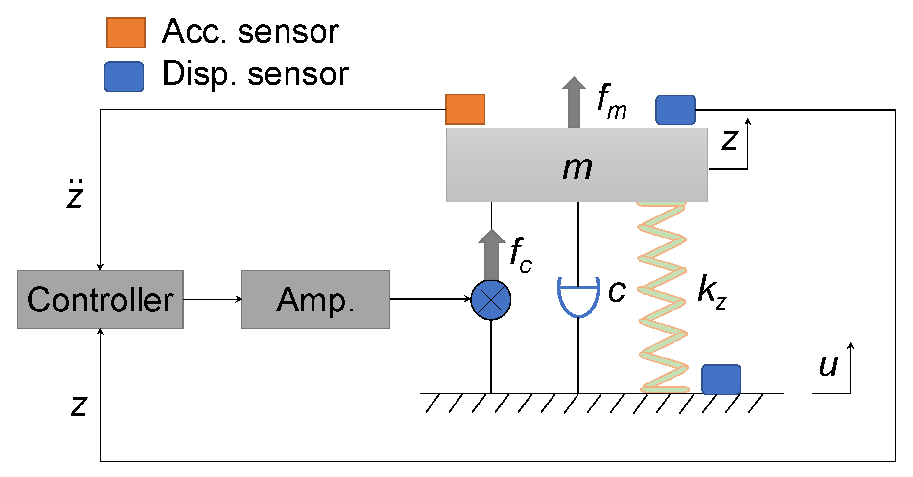
The control model of the electromagnetic actuator is shown in Figure 9. It is assumed that only the z-axis motion of the controlled object is considered, and that the interference of the z-axis motion to other directions is neglected. The dynamics model in the z-axis is given as follows:
m z ¨ + c z ˙ + k z ( z u ) = f c + f m
f c = k i · i
where z is the displacement of the controlled object, m is the mass of the controlled object, c is the damping coefficient, kz is the parallel stiffness of three springs, fc is the output force of the electromagnetic actuator, fm is the external disturbance force, u is the displacement of the input excitation, ki is the output force–current coefficient of the electromagnetic actuator, and i is the current of the coil2. These parameters were established using the experimental and simulated results, as shown in Table 5.

4.2. Controller Design

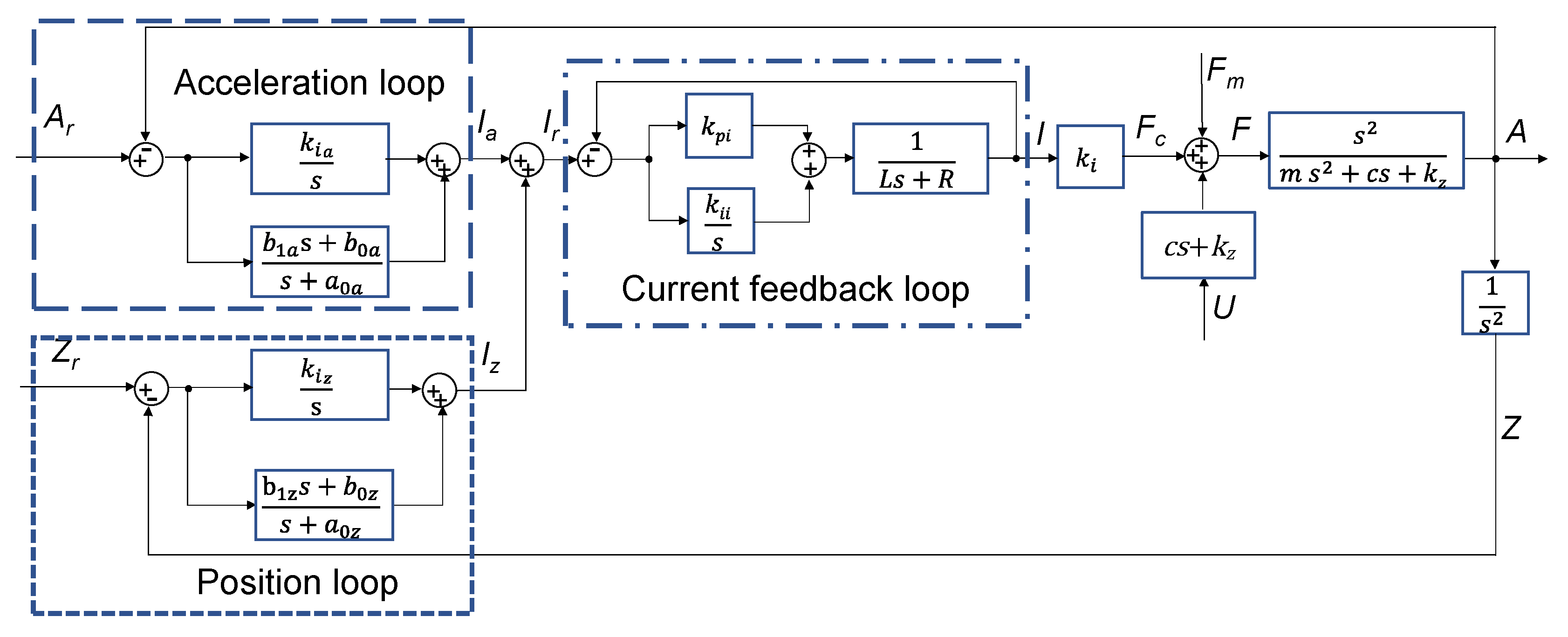
Figure 10 is a block diagram of the electromagnetic actuator control system in the z-axis, which includes an acceleration controller and a position controller. The acceleration controller is composed of a regulator consisting of a 1st order numerator, 1st order denominator, and an integrating compensator. The position controller is the same as the acceleration controller. To improve the response speed of the output force, a local current feedback loop using a proportional-integral (PI) controller has been added.
Assuming that the bandwidth of the current feedback loop is infinite [i.e., that (s)/Ir(s) = 1] and that the integrating compensators can be neglected, the transfer function of the acceleration loop (A/Ar) is shown in Equation (3). Based on this, the controller parameters a0a, b1a, and b0a can be automatically defined, such that the denominator of the transfer function (A/Ar) approaches (m + kib1a)×(s + p1)3 after deciding only on the value of pole p1, as shown in Equation (4). The control principle of the position loop is the same as for the acceleration loop. The transfer function of the position loop (Z/Zr) is shown in Equation (5), and adjusting the value of pole p2 can change a0z, b1z, and b0z, as shown in Equation (6). The parameters of the integral compensators in the acceleration loop and the position loop were adjusted by experiments here. When p1 and p2 were set to −31.4 and −314, and the values of the PI controller parameters kpi and kii were set to 60 and 1000, respectively, the decided controller parameters were recorded, and these are shown in Table 6 and Table 7. Compared with the proportion integral derivative (PID) controller, this controller has the advantages of having a simple structure, fewer adjustment parameters, and the characteristic of saving time.
A ( s ) A r ( s ) = k i b 1 a s 3 + k i b 0 a s 2 ( m + k i b 1 a ) s 3 + ( c + m a 0 a + k i b 0 a ) s 2 + ( k z + c a 0 a ) s + k z a 0 a
{ a 0 a = 1 k i p 1 3 ( m + k i b 1 a ) b 1 a = 1 k i ( m + k z 2 3 k z p 1 2 c p 1 3 ) b 0 a = 1 k i [ c m a 0 a + 3 p 1 ( m + k i b 1 a ) ]
Z ( s ) Z r ( s ) = k i b 1 z s + k i b 0 z m s 3 + ( c + m a 0 z ) s 2 + ( k + c a 0 z + k i b 1 z ) s + k a 0 z + k i b 0 z
{ a 0 z = 3 p 2 c m b 1 z = 1 k i ( k z c a 0 z + 3 m p 2 2 ) b 0 z = 1 k i ( m p 2 3 k z a 0 z )

5. Experimental Results

5.1. Experimental Control System

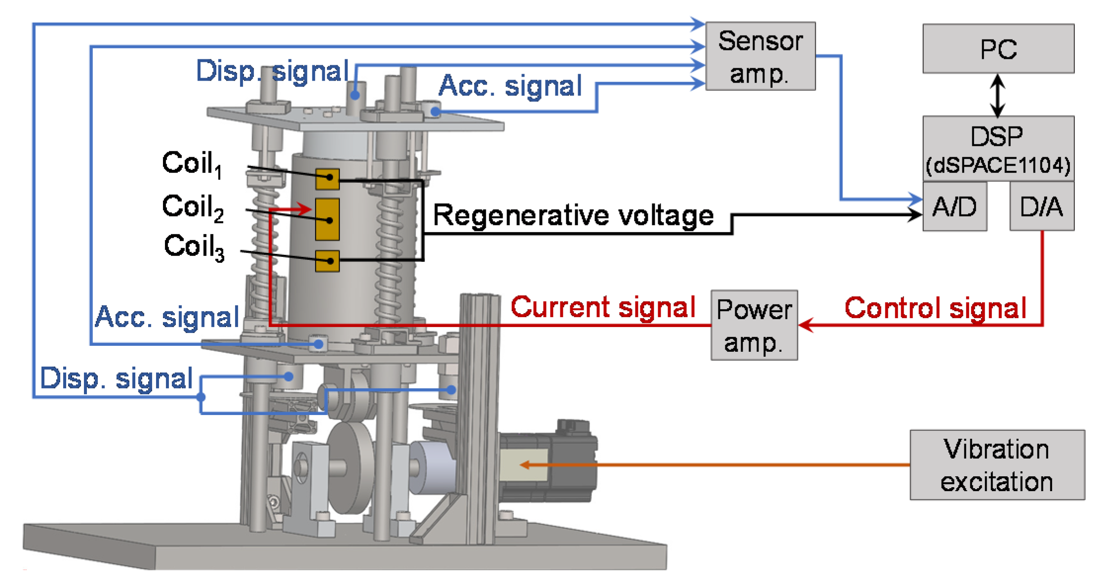
As shown in Figure 11, the schematic of the electromagnetic actuator shows signal loops of the control system for various physical quantities. The vibration excitation is carried out by the motor driving the cam, where the vibration generated by the cam is then transmitted to the excitation object, electromagnetic actuator, and controlled object. The electromagnetic actuator is controlled by a DSP (DS1104, dSPACE Corp.), and the sampling rate was set to 10 kHz. Two acceleration sensors and three displacement sensors were connected to the A/D converter of the DSP. The control signal acts as an output to the D/A converter of the DSP via a power amplifier applied to coil2. Coil1 and coil3 are connected in series, and the voltage signal is transmitted to the A/D converter of the DSP for regenerating the EMF.

5.2. Impulse Excitation Response

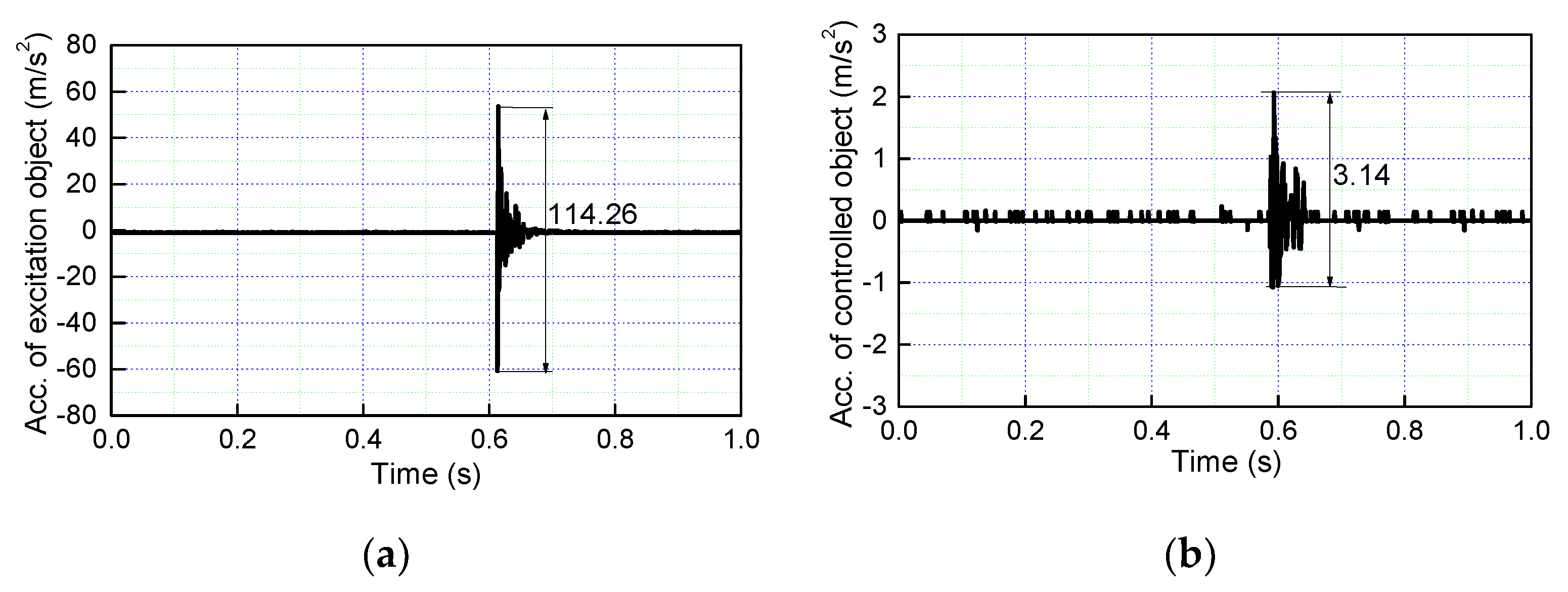
In the impulse excitation experiment, the acceleration signals of the excitation object and controlled object are measured. A rubber hammer hits the excitation object, the impulse excitation response results of the electromagnetic actuator are shown in Figure 12. The peak to peak value of the acceleration of the excitation object is 114.26 m/s2, and the peak to peak value of the acceleration of the controlled object is 3.14 m/s2. It can be seen that the acceleration of the controlled object is smaller than that of the excitation object, and that the acceleration ratio of the controlled object to the excitation object is 2.75%. The experimental results show that the proposed actuator can evidently decrease the external impulse disturbance.

5.3. Sinusoidal Excitation Response

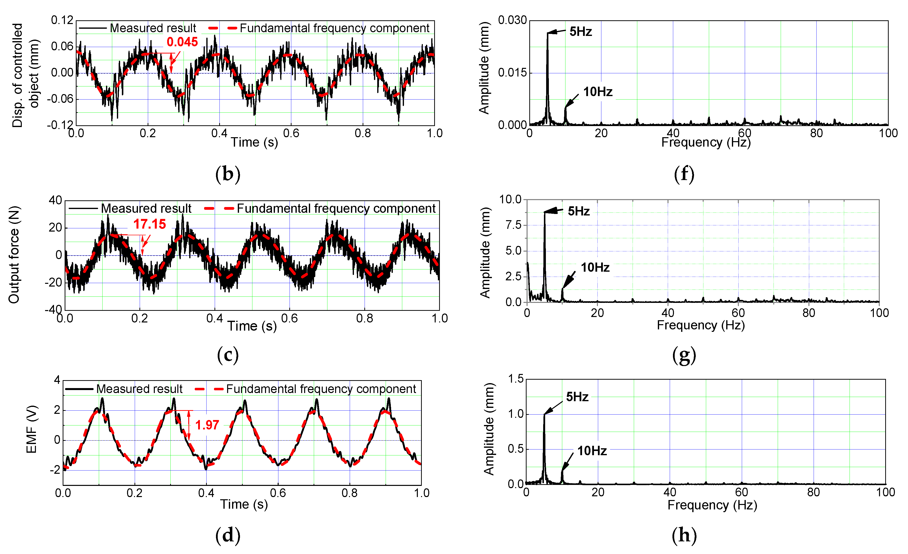
To verify the vibration suppression and energy regeneration effect of the electromagnetic actuator, the sinusoidal excitation signal with a 3 mm amplitude and 5 Hz frequency was used as the input signal, the experimental results of which are shown in Figure 13. In Figure 13b–d, the fundamental frequency components of the displacement of the controlled object, output force, and EMF were extracted by a low-pass filter with a cutoff frequency of two-times that of the excitation frequency.
The peak value of the input displacement was 3.045 mm, which was caused by a manufacturing error of the cam. In Figure 13a, the peak value of the base harmonic of the controlled object displacement is 0.045 mm, accounting for 1.46% of the excitation object displacement in Figure 13b, and there is a quarter period of phase difference between the displacement of the excitation object and the controlled object. The output force of the electromagnetic actuator was calculated and deduced by measuring the coil2 current. The peak value of the base harmonic of the output force was 17.15 N, as shown in Figure 13c. Figure 13d shows that the peak value of the base harmonic of the EMF for the energy regeneration function was 1.97 V. Figure 13e–h show the results of fast fourier transform (FFT) analysis for the input displacement of the excitation object, displacement of the controlled object, output force, and EMF, respectively. The displacement of the excitation object contains the fundamental frequency components of 5 Hz, 10 Hz, and its other harmonics, which are caused by the machining error of the cam. The displacement of the controlled object, output force and EMF contain the fundamental frequency components of 5 Hz, 10 Hz and their other harmonics, which are brought about by the machining error of the cam and pulse width modulation (PWM) of the motor. These amplitudes at a 5 Hz fundamental frequency are much higher than the ones at their harmonic frequencies, and therefore, the experimental results were filtered to eliminate the influences of the harmonics.
To estimate the efficiency of energy regeneration of the electromagnetic actuator, energy supplied to the electromagnetic actuator in a period of 0.2 s, and regenerated energy in a period of 0.2 s, were calculated. The efficiency of the proposed actuator is a ratio of regenerated energy in a period of 0.2 s to energy supplied to the electromagnetic actuator in a period of 0.2 s. According to the output force of the electromagnetic actuator and the velocity calculated by the displacement of the controlled object, energy supplied to the electromagnetic actuator in a period of 0.2 s is 0.164 J. Assuming that the external resistance is 0 Ω, the series resistances of coil1 and coil3 are 20.45 Ω, therefore, regenerated energy in a period of 0.2 s is 0.019 J, and the efficiency of the proposed electromagnetic actuator is 11.59%. The generated electromotive force is relatively small and cannot charge the battery, and therefore, the electromotive force can be increased by a voltage boosting circuit, or by considering a new structure to improve the energy regeneration efficiency of the proposed actuator in the future.
The vibration control and energy regeneration experiments were carried out when the sinusoidal excitation signals were respectively set to various amplitudes and frequencies. All the experimental results are expressed by the amplitude ratio and the ratio of the EMF to the input amplitude, as shown in Figure 14. The amplitude ratio is defined as the ratio of the amplitude of the controlled object to the excitation object in the fundamental frequency component, and the ratio of the EMF to the input amplitude is defined as the ratio of the regenerated EMF to the input amplitude of the excitation object in the fundamental frequency component. When the input amplitudes were 1 mm, 2 mm, and 3 mm, the lowest frequency was 1 Hz and the highest frequencies were 7 Hz, 10 Hz, and 15 Hz, respectively. As shown in Figure 14a, the amplitude ratios are in the range of 0% to 5.5%. According to the trends of these three curves, as the amplitude and frequency of the excitation signals increase, the effect of vibration suppression decreases. In the future, we plan to change the controller of the actuator to improve the vibration suppression effect. As shown in Figure 14b, the ratios of the EMF to the amplitude of the three curves from 1 mm to 3 mm input amplitudes are 0.128, 0.125, and 0.127. When the frequency increases, the ratio of the EMF to the input amplitude also increases.

6. Conclusions

This paper has proposed a new type of electromagnetic actuator that may be applied in mechanisms with low vibration and a low frequency, such as in transportation machinery, mining machinery, construction machinery, and other areas. The proposed actuator has two working functions, namely, a vibration suppression function and an energy regeneration function. These functions can relieve vibrations generated by a vibrating component and collect a part of the energy dissipated by the vibrating component. The structure of the electromagnetic actuator was designed by the static magnetic field simulation of FEM analysis, and the prototype of the actuator was fabricated. On this basis, the characteristics of the electromagnetic actuator were explored, finding an output force–current coefficient of 39.49 N/A. Moreover, the control system of the experiments was constructed by a position controller and an acceleration controller. Impulse excitation response and sinusoidal excitation response analyses were carried out. The experimental results show that the vibration acceleration of the controlled object can be suppressed from 114.26 m/s2 to 3.14 m/s2, which is within 2.75% under the impulse excitation response. For the sinusoidal excitation response, the input signal under a 3 mm amplitude and 5 Hz frequency was set as the input of the excitation object, where the peak value of the displacement of the controlled object was 0.045 mm, accounting for 1.46% of that of the excitation object. The peak value of the regenerated EMF was 1.97 V, where the efficiency for regenerating energy is 11.59%. Under multiple frequencies and amplitudes, the amplitude ratio of the controlled object and excitation object was within 5.5%, and ratio of the EMF to the input amplitude was 0.13, which can predict the trend of the regenerated energy.
This electromagnetic actuator has great potential to be adopted as a viable development for occasions with millimeter-sized vibrations. The next step is to conduct a thorough study of the amplitude ratio of the controlled object to excitation object, and the ratio of the EMF to the input amplitude, to improve the control effect at high frequencies in the active control function. In the energy regeneration function, the efficiency of the proposed electromagnetic actuator will be verified by experiments, and this efficiency needs to be further improved.

Author Contributions

Conceptualization, W.W. and X.Z. methodology, W.W.; X.Z.; F.S. software, W.W.; Q.L. and X.Z. validation, F.X.; J.J. (Junjie Jin) and J.J. (Jiaqi Jin) resources, W.W.; Q.L. and X.Z. writing—original draft preparation, W.W. writing—review and editing, X.Z. and F.S. supervision, X.Z. and F.S. project administration, X.Z., Q.L. and F.S. funding acquisition, X.Z. and F.S. All authors have read and agreed to the published version of the manuscript.

Funding

This research is supported by the LiaoNing Revitalization Talents Program (number XLYC1802077) and the Scientific Research Fund Project of the Liaoning Provincial Department of Education (number LJGD2019011).

Acknowledgments

The authors would like to express their thanks to the LiaoNing Revitalization Talents Program and the Scientific Research Fund Project of the Liaoning Provincial Department of Education.

Conflicts of Interest

The authors declare no conflict of interest.

References

  1. Hoque, M.E.; Mizuno, T.; Ishino, Y.; Takasaki, M. A three-axis vibration isolation system using modified zero-power controller with parallel mechanism technique. Mechatronics 2011, 6, 1055–1062. [Google Scholar] [CrossRef]
  2. Fu, J.; Li, P.; Liao, G.; Lai, J.; Yu, M. Development and dynamic characterization of a mixed mode magnetorheological elastomer isolator. IEEE T. Magn. 2017, 53, 13–17. [Google Scholar] [CrossRef]
  3. Beltran-Carbajal, F.; Valderrabano-Gonzalez, A.; Favela-Contreras, A.; Hernandez-Avila, J.L.; Lopez-Garcia, I.; Tapia-Olvera, R. An active vehicle suspension control approach with electromagnetic and hydraulic actuators. Actuators 2019, 8, 35. [Google Scholar] [CrossRef] [Green Version]
  4. Pomorski Linessio, R.; Sousa, K.D.M.; Silva, T.D.; Bavastri, C.A.; Antunes, P.F.D.C.; Silva, J.C.C.D. Induction motors vibration monitoring using a viaxial optical fiber accelerometer. IEEE Sens. J. 2016, 16, 8075–8082. [Google Scholar] [CrossRef]
  5. Liu, H.; Cui, S.; Liu, Y.; Ren, Y.; Sun, Y. Design and Vibration Suppression Control of a Modular Elastic Joint. Sensors 2018, 18, 1869. [Google Scholar] [CrossRef] [Green Version]
  6. Braz César, M.; Coelho, J.P.; Gonçalves, J. Semi-active vibration control of a non-collocated civil structure using evolutionary-based BELBIC. Actuators 2019, 8, 43. [Google Scholar] [CrossRef] [Green Version]
  7. Chen, A.; He, G. Wind-induced vibration analysis and remote monitoring test of wind turbine power tower. Adv. Mater. Res. 2013, 639–640, 293–296. [Google Scholar] [CrossRef]
  8. Zhang, B.; Li, Y. Nonlinear vibration of rotating pre-deformed blade with thermal gradient. Nonlinear Dyn. 2016, 86, 459–478. [Google Scholar] [CrossRef]
  9. Xu, Z.; Xu, F.; Chen, X. Vibration suppression on a platform by using vibration isolation and mitigation devices. Nonlinear Dyn. 2016, 83, 1341–1353. [Google Scholar] [CrossRef]
  10. Le, T.D.; Ahn, K.K. Experimental investigation of a vibration isolation system using negative stiffness structure. Int. J. Mech. Sci. 2013, 70, 99–112. [Google Scholar] [CrossRef]
  11. Wu, Q.; Cui, N.; Zhao, S.; Zhang, H.; Liu, B. Modeling and control of a six degrees of freedom maglev vibration isolation system. Sensors 2019, 19, 3608. [Google Scholar] [CrossRef] [PubMed] [Green Version]
  12. Moradi, H.; Vossoughi, G.; Behzad, M.; Movahhedy, R.M. Vibration absorber design to suppress regenerative chatter in nonlinear milling process: Application for machining of cantilever plates. Appl. Math. Model. 2015, 39, 600–620. [Google Scholar] [CrossRef]
  13. Rosbi, S.; Ryu, T.; Nakae, T.; Matsuzaki, K.; Sueoka, A.; Takikawa, Y.; Ooi, Y. Evaluation of dynamic absorber to suppress subharmonic nonlinear vibration in car powertrain. Mech. Eng. J. 2015, 2, 14–00528. [Google Scholar] [CrossRef] [Green Version]
  14. Stelzer, G.J.; Schulz, M.J.; Kim, J.; Allemang, R.J. A magnetorheological semi-active isolator to reduce noise and vibration transmissibility in automobiles. J. Intell. Mater. Syst. Struct. 2003, 14, 743–765. [Google Scholar] [CrossRef]
  15. Yang, J.; Xiong, Y.P.; Xing, J.T. Vibration power flow and force transmission behaviour of a nonlinear isolator mounted on a nonlinear base. Int. J. Mech. Sci. 2016, 115–116, 238–252. [Google Scholar] [CrossRef]
  16. Wang, X.; Zhou, J.; Xu, D.; Ouyang, H.; Duan, Y. Force transmissibility of a two-stage vibration isolation system with quasi-zero stiffness. Nonlinear Dyn. 2017, 87, 633–646. [Google Scholar] [CrossRef]
  17. Zhang, X.; Wang, C.; Gao, R.X.; Yan, R.; Chen, X.; Wang, S. A novel hybrid error criterion-based active control method for on-line milling vibration suppression with piezoelectric actuators and sensors. Sensors 2016, 16, 68. [Google Scholar] [CrossRef] [Green Version]
  18. Lou, J.; Wei, Y.; Li, G.; Yang, Y.; Xie, F. Optimal trajectory planning and linear velocity feedback control of a flexible piezoelectric manipulator for vibration suppression. Shock Vib. 2015, 2015, 952708. [Google Scholar] [CrossRef] [Green Version]
  19. Zhou, D.; Yu, P.; Wang, L.; Li, J. An adaptive vibration control method to suppress the vibration of the maglev train caused by track irregularities. J. Sound Vib. 2017, 408, 331–350. [Google Scholar] [CrossRef]
  20. Kotake, S.; Yagi, K.; Takigami, T. Application of sampled-data control by using vibration manipulation function to suppress residual vibration of travelling crane. Mech. Eng. J. 2015, 2, 15–00033. [Google Scholar] [CrossRef] [Green Version]
  21. Shao, X.; Naghdy, F.; Du, H. Reliable fuzzy H∞ control for active suspension of in-wheel motor driven electric vehicles with dynamic damping. Mech. Syst. Signal Process. 2017, 87, 365–383. [Google Scholar] [CrossRef]
  22. Ze, Q.; Liang, D.; Kou, P.; Yu, Y. Improvement of power generation performance in a doubly salient permanent magnet generator with a capacitive energy recovery converter. IET Electr. Power Appl. 2017, 11, 108–120. [Google Scholar]
  23. Warner, H.; Simon, D.; Richter, H. Design optimization and control of a crank-slider actuator for a lower-limb prosthesis with energy regeneration. In Proceedings of the 2013 IEEE 13th International Conference on Rehabilitation Robotics (ICORR), Banff, AB, Canada, 12–15 July 2016; pp. 1–6. [Google Scholar]
  24. Manna, B.P.; Sims, N.D. Energy harvesting from the nonlinear oscillations of magnetic levitation. J. Sound Vib. 2009, 319, 515–530. [Google Scholar] [CrossRef] [Green Version]
  25. Elvin, N.G.; Elvin, A.A. An experimentally validated electromagnetic energy harvester. J. Sound Vib. 2011, 330, 2314–2324. [Google Scholar] [CrossRef]
  26. Glynne-Jones, P.; Tudor, M.J.; Beeby, S.P.; White, N.M. An electromagnetic, vibration-powered generator for intelligent sensor systems. Sens. Actuators A 2004, 110, 344–349. [Google Scholar] [CrossRef] [Green Version]
  27. Xu, G.; Xu, K.; Zheng, C.; Zhang, X.; Zahid, T. Fully electrified regenerative braking control for deep energy recovery and safety maintaining of electric vehicles. IEEE Trans. Veh. Technol. 2016, 65, 1186–1198. [Google Scholar] [CrossRef]
  28. Zhang, X.; Göhlich, D.; Li, J. Energy-Efficient Toque Allocation Design of Traction and Regenerative Braking for Distributed Drive Electric Vehicles. IEEE Trans. Veh. Technol. 2018, 67, 285–295. [Google Scholar] [CrossRef]
  29. Yan, S.; Sun, W. Self-powered suspension criterion and energy regeneration implementation scheme of motor-driven active suspension. Mech. Syst. Signal Process. 2017, 94, 297–311. [Google Scholar] [CrossRef]
  30. Khaligh, A.; Zeng, P.; Zheng, C. Kinetic energy harvesting using piezoelectric and electromagnetic technologies—State of the art. IEEE Trans. Ind. Electron. 2010, 57, 850–860. [Google Scholar] [CrossRef]
  31. Maravandi, A.; Mehrdad, M. Regenerative shock absorber using a two-leg motion conversion mechanism. IEEE ASME Trans. Mech. 2015, 20, 2853–2861. [Google Scholar] [CrossRef]
  32. Liu, Y.; Xu, L.; Zuo, L. Design, modeling, lab, and field tests of a mechanical-motion-rectifier-based energy harvester using a ball-screw mechanism. IEEE ASME Trans. Mech. 2017, 22, 1933–1943. [Google Scholar] [CrossRef]
  33. Jiang, L.; Zhang, W.; Ma, G.J.; Wu, C.W. Shape optimization of energy storage flywheel rotor. Struct. Multidiscip. Optim. 2017, 55, 739–750. [Google Scholar] [CrossRef]
  34. Asadi, E.; Ribeiro, R.; Khamesee, M.B.; Khajepour, A. Analysis, prototyping, and experimental characterization of an adaptive hybrid electromagnetic damper for automotive suspension systems. IEEE Trans. Veh. Technol. 2017, 66, 3703–3713. [Google Scholar] [CrossRef]
  35. Buren, T.; Troster, G. Design and optimization of a linear vibration-driven electromagnetic micro-power generator. Sens. Actuators A 2007, 135, 765–775. [Google Scholar] [CrossRef]
  36. Arroyo, E.; Badel, A.; Formosa, F. Energy harvesting from ambient vibrations: Electromagnetic device and synchronous extraction circuit. J. Intell. Mater. Syst. Struct. 2013, 24, 2023–2035. [Google Scholar] [CrossRef]
  37. Tang, X.; Lin, T.; Zuo, L. Design and optimization of a tubular linear electromagnetic vibration energy harvester. IEEE ASME Trans. Mechatron. 2014, 19, 615–622. [Google Scholar] [CrossRef]
  38. Sapiński, B. Energy-harvesting linear MR damper: Prototyping and testing. Smart Mater. Struct. 2014, 23, 035021. [Google Scholar] [CrossRef]
  39. Gljuš’ci’c, P.; Zelenika, S.; Blaževi´c, D.; Kamenar, E. Kinetic energy harvesting for wearable medical sensors. Sensors 2019, 19, 4922. [Google Scholar] [CrossRef] [Green Version]
  40. Liu, H.; Tay, J.; Quan, C.; Kobayashi, T.; Lee, C. Piezoelectric MEMS energy harvester for low-frequency vibrations with wideband operation range and steadily increased output power. J. Microelectromec. Syst. 2011, 20, 1131–1142. [Google Scholar] [CrossRef]
  41. Liu, H.; Cong, C.; Cao, C.; Zhao, Q. Analysis of the key factors affecting the capability and optimization for magnetostrictive iron-gallium alloy ambient vibration harvesters. Sensors 2020, 20, 401. [Google Scholar] [CrossRef] [Green Version]
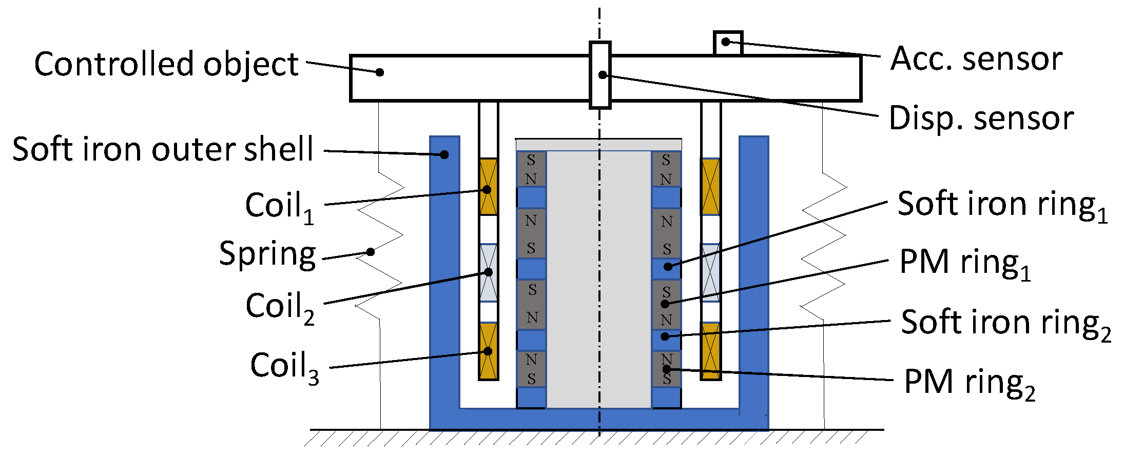
Figure 1. Structure of the electromagnetic actuator.
Actuators 09 00042 g001
Figure 2. The vibration suppression function and energy regeneration function.
Actuators 09 00042 g002
Figure 3. Configuration of the electromagnetic actuator.
Actuators 09 00042 g003
Figure 4. Magnetic flux distribution for the electromagnetic actuator: (a) Main magnetic loops; (b) magnetic flux distribution based on the FEM analysis.
Actuators 09 00042 g004
Figure 5. Output force–current relationship of the electromagnetic actuator.
Actuators 09 00042 g005
Figure 6. Prototype of the proposed actuator.
Actuators 09 00042 g006
Figure 7. Experimental devices and results for measuring the magnetic field: (a) Experimental devices; (b) axial displacement and magnetic flux density relationship.
Actuators 09 00042 g007
Figure 8. Experimental devices and measured results for measuring the output force: (a) Experimental devices; (b) output force–current relationship.
Actuators 09 00042 g008
Figure 9. Control model of the electromagnetic actuator.
Actuators 09 00042 g009
Figure 10. Block diagram of the electromagnetic actuator.
Actuators 09 00042 g010
Figure 11. Schematic of the control system.
Actuators 09 00042 g011
Figure 12. Impulse excitation response of the electromagnetic actuator: (a) Measured acceleration (acc.) of the excitation object; (b) measured acceleration (acc.) of the controlled object.
Actuators 09 00042 g012
Figure 13. Sinusoidal excitation experimental results with a 3 mm amplitude and 5 Hz frequency: (a) The input displacement (disp.); (b) measured displacement (disp.) of the controlled object; (c) measured output force of the electromagnetic actuator; (d) measured electromotive force (EMF); (e) Fast fourier transform (FFT) analysis result of the input displacement; (f) FFT analysis result of the controlled object displacement; (g) FFT analysis result of the output force; (h) FFT analysis result of the EMF.
Actuators 09 00042 g013aActuators 09 00042 g013b
Figure 14. Vibration control and energy regeneration experimental results: (a) Amplitude ratio of the controlled object to excitation object; (b) ratio of the EMF to the input amplitude.
Actuators 09 00042 g014
Table 1. Factors and levels in the orthogonal experiment method.
LevelHeight of Coil2 (mm)
A
Thickness of Coil2 (mm)
B
Height of Soft Iron Ring1 (mm)
C
13058
235610
340812
Table 2. Size optimization simulations of the actuator by the orthogonal experiment method.
NumberHeight of Coil2
(mm)
Thickness of Coil2
(mm)
Height of Soft Iron Ring1
(mm)
Output Force
(N)
1A1B1C143.45
2A1B2C250.40
3A1B3C366.14
4A2B1C245.80
5A2B2C354.15
6A2B3C167.57
7A3B1C347.68
8A3B2C156.30
9A3B3C272.78
Table 3. Analysis by the orthogonal experiment method.
Value NameHeight of Coil2
(mm)
Thickness of Coil2
(mm)
Height of Soft Iron Ring1
(mm)
Kj1159.99136.93167.32
Kj2167.52160.85168.98
Kj3176.76206.49167.97
Kjp155.3345.6455.77
Kjp255.8453.6256.33
Kjp358.9268.8355.99
Rj5.5923.190.55
Primary and secondary orderB > A > C
Optimal levelsA3B3C2
Optimal combinationA3B3C2
Table 4. Main parameters of the electromagnetic actuator.
SymbolDescriptionValue (mm)
ΦcCoils outer diameter64.2
ΦoOuter diameter of soft iron outer shell78
ΦsPM rings outer diameter, soft iron rings outer diameter39
φsPM rings inner diameter19
hoStator height115
hm1PM ring1 height30.9
hm2PM ring2 height7
hi1Height of soft iron ring110
hi2Height of soft iron ring25
hc1Coil1 and coil3 height20
hc2Coil2 height40
wcCoils thickness8
Table 5. Parameters of the electromagnetic actuator.
SymbolValue
m1.37 (kg)
kz4.2 (kN/m)
L21.98 (mH)
R221 (Ω)
c5.0 (N/(m/s))
ki39.49 (N/A)
Table 6. Parameters of the acceleration loop.
SymbolValue
a0a10.5
b1a1.3 × 10−3
b0a3.0
kia0
Table 7. Parameters of the position loop.
SymbolValue
a0z1.13 × 103
b1z1.46 × 104
b0z1.74 × 106
kiz80