Article

Multi-Fidelity Design Optimisation of a Solenoid-Driven Linear Compressor

1
Thermo and Fluid dynamics (FLOW) Faculty of Engineering, Vrije Universiteit Brussel (VUB) Pleinlaan 2, 1050 Brussels, Belgium
2
Mobility Logistic and Automotive Technology Research Group (MOBI), Department of Electrical Engineering and Energy Technology (ETEC), Vrije Universiteit Brussel, Pleinlaan 2, 1050 Brussels, Belgium
3
Combustion and Robust optimisation Group (BURN), Vrije Universiteit Brussel (VUB) and Université Libre de Bruxelles (ULB), 1050 Brussels, Belgium
4
Thermal Engineering and Combustion Unit, University of Mons (UMONS), Place du Parc 20, 7000 Mons, Belgium
5
Institute of Mechanics, Materials and Civil Engineering (iMMC), Université catholique de Louvain (UCLouvain), Place du Levant, 2, 1348 Louvain-la-Neuve, Belgium
6
Flanders Make, 3001 Heverlee, Belgium
7
Robotics & Multibody Mechanics Research Group (R&MM), Faculty of Mechanical Engineering, Vrije Universiteit Brussel, 1050 Brussels, Belgium
*
Author to whom correspondence should be addressed.
Actuators 2020, 9(2), 38; https://doi.org/10.3390/act9020038
Submission received: 8 April 2020 / Revised: 7 May 2020 / Accepted: 8 May 2020 / Published: 11 May 2020

Abstract

:
Improved management and impermeability of refrigerants is a leading solution to reverse global warming. Therefore, crank-driven reciprocating refrigerator compressors are gradually replaced by more efficient, oil-free and hermetic linear compressors. However, the design and operation of an electromagnetic actuator, fitted on the compression requirements of a reciprocating linear compressor, received limited attention. Current research mainly focuses on the optimisation of short stroke linear compressors, while long stroke compressors benefit from higher isentropic and volumetric efficiencies. Moreover, designing such a system focuses mainly on the trade-off between number of copper windings and the current required, due to the large computational cost of performing a full geometric design optimisation based on a Finite Element Method. Therefore, in this paper, a computationally-efficient, multi-objective design optimisation for six geometric design parameters has been applied on a solenoid driven linear compressor with a stroke of 44.2 mm. The proposed multi-fidelity optimisation approach takes advantage of established models for actuator optimisation in mechatronic applications, combined with analytical equations established for a solenoid actuator to increase the overall computational efficiency. This paper consists of the multi-fidelity optimisation algorithm, the analytic model and Finite Element Method of a solenoid and the optimised designs obtained for optimised power and copper volume, which dominates the actuator cost. The optimisation results illustrate a trade-off between minimising the peak power and minimising the volume of copper windings. Considering this trade-off, an intermediate design is highlighted, which requires 33.3% less power, at the expense of an increased copper volume by 5.3% as opposed to the design achieving the minimum copper volume. Despite that the effect of the number of windings on the input current remains a dominant design characteristic, adapting the geometric parameters reduces the actuator power requirements significantly as well. Finally, the multi-fidelity optimisation algorithm achieves a 74% reduction in computational cost as opposed to an entire Finite Element Method optimisation. Future work focuses on a similar optimisation approach for a permanent magnet linear actuator.

1. Introduction

Project Drawdown, the world’s leading source of climate solutions, describes the management and destruction of refrigerants in circulation and the avoidance of further leaks as a leading solution to reverse global warming [1]. Therefore, crank-driven reciprocating refrigerator compressors are being replaced by more efficient [2,3,4], oil-free, hermetic [5] linear compressors, as it increases energy saving and ensures the adequate handling of the refrigerants. Given that in a conventional refrigerator compressor, the rotary motion of the rotor is converted into a linear motion using a crank mechanism, an oil-free hermetic solution is unfeasible. Instead, in linear compressors, a free piston is employed to acquire a linear motion, which reduces the number of mechanical components in the system and allows for a more compact and hermetic solution [6]. However, linear compressors suffer from a reduced volumetric efficiency as opposed to crank-driven reciprocating compressors, where the kinematics of the piston are fixed. Consequently, advanced (and expensive) control strategies are required to improve volumetric efficiency and to avoid collision of the piston with the housing, while minimising the clearance volumes [7,8]. The use of these advanced control strategies allows to adapt the operating conditions, e.g., oscillation on the resonance frequency of the system, in order to further increase the overall efficiency of the compressor [9,10,11,12]. To simplify these control algorithms (and the associated hardware), components such as mechanical springs are implemented, which increase the piston compressor complexity, (e.g., intensifying mechanical wear, increasing the acoustic noise, etc. [13,14]).
Recently, dedicated developments are reported in the area of linear motor technology contributing to the evolution of linear compressors in the refrigeration world [15,16]. Linear motors are often categorised in three different configurations: moving coil, moving magnet and moving iron. These configurations have been investigated for compressor applications and compared for power efficiency at different stroke positions [17]. Similar work has been conducted for the different linear compressor types in which the effect of the compressed gas on the piston has been expressed by an equivalent damping coefficient and a gas–spring stiffness [18,19,20,21,22]. Furthermore, Chen et al. studied the static and dynamic performance of moving magnet linear compressors to identify the optimal points of the linear compressor [23]. The analytical model of the electromagnetic force for the solenoid type linear actuators, i.e., moving iron or reluctance type, allowed to initiate simulations including the nonlinearity of both the electromagnetic force and gas force [24,25]. Previous concepts have been expanded for high-frequency applications, where more complex electromagnetic actuation concepts were investigated, consisting of specific permanent magnet configurations such as Halbach-arrays [26].
Clearly, both (thermo-)mechanical and electromagnetic aspects of the linear compressor have to be considered as one complex system during the design process. This can be done iteratively by investigating each system separately or as one system in a global optimisation process. To optimise the design of such complex systems for multiple objectives, metaheuristic optimisation strategies are favoured, such as Particle Swarm optimisation [27] and Nondominated Sorting Genetic Algorithm (NSGA-II) [28,29,30]. Rao et al. performed a multi-objective optimisation via a genetic algorithm of double-acting hybrid active magnetic thrust bearings, subject to geometric, electrical and control constraints [31]. Lee et al. designed an electromagnetic engine valve in a combustion engine using a genetic algorithm [32]. Finally, Leati et al. presented the design of an electromagnetically actuated high-frequency oscillation pump in a multi-objective optimisation framework [33]. The NSGA-II optimisation algorithm has been used in a multi-fidelity optimisation framework as well. Ciarella et al. combine a high-fidelity Computational Fluid Dynamics model with a low-fidelity model for the aeroelastic problem for the design optimisation of a morphing wing [34], while Reitenbach et al. optimise the compressor variable geometry settings by running a 2-dimensional flow calculation and a 0-dimensional performance evaluation [35].
Despite the recent increased interest, the design and operation of an electromagnetic linear actuator fitted on the compression requirements of a reciprocating compressor requires further research to avoid the use of oversized and expensive linear motors. Furthermore, current research mainly focuses on the optimisation of small stroke linear compressors and pumps (<20 mm) [33,36,37], while longer strokes provide significant benefits, such as enhanced heat dissipation and increased isentropic and volumetric efficiency [38]. Poltschak detailed a finite-element-based design of a linear permanent magnet synchronous motor for a 50 mm stroke reciprocating compressor [15]. Lazoglu et al. presented the analytical modelling of an oil-free, solenoid-based linear compressor used in household refrigerators for a stroke of 23 mm [25]. Generally, such solenoid actuators are designed based on a trade-off between the number of windings and operating current, which can lead to sub-optimal designs in terms of performance and cost. However, to refine the design process for both performance and cost, considering additional geometric parameters becomes computationally intractable in a Finite Element Method (FEM) framework. Therefore, we propose a multi-fidelity design optimisation approach by merging the established design rules and models for actuator optimisation in mechatronic applications [39] with an extension of the analytical equations established for a solenoid actuator [25]. This method enables the design optimisation of a (single coil) solenoid actuator with respect to the compression requirements of an existing compressor with a stroke of 44.2 mm, subject to six geometrical parameters, with the current and current peak position as design parameters. The importance of these design parameters are analysed through the optimised designs, which represent the trade-off between minimising cost and maximising performance. The optimisation procedure suggested in this paper could furthermore be easily adapted for other domains where computationally expensive simulations are required upon optimising.
This paper starts first by defining the configuration of a chosen test case, a reciprocating air compressor kit. Afterwards, the focus shifts towards a brief description of the analytical and FEM-models of a solenoid actuator, both validated experimentally, before presenting the different parameters and thermodynamic and electromagnetic constraints of the optimisation process. To conclude, the optimisation parameters and their corresponding ranges are provided as well as a detailed overview of the multi-fidelity optimisation process and results. The focus lies thus on the optimisation of the actuator with respect to the compression requirements in the design stage before taking the dynamics of the multiple domains into account.

2. Compressor Design

In this section, the configuration of the reciprocating compressor kit is illustrated, followed by the analytical and finite element models of the solenoid actuator as well as their experimental validation. To conclude, an initial comparison between the electromagnetic force profiles and compression requirements is provided.

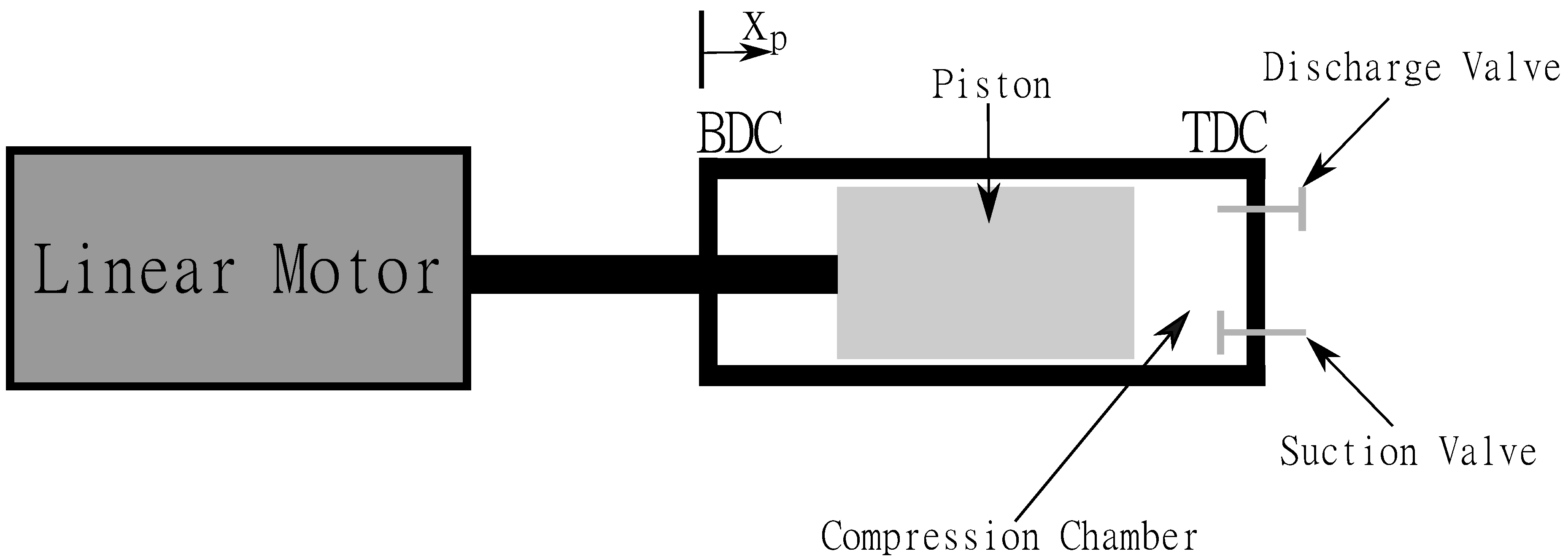
2.1. Reciprocating Compressor Kit RCK-1 Configuration

For this research, the Bently Nevada Reciprocating Compressor Kit RCK-1 [40] will be used as a reference and future test case. The RCK-1 is a crank-driven reciprocating air compressor kit, where the slider-crank mechanism will be omitted and the piston/cylinder part will be adapted to provide a rigid connection with an electromagnetic actuator for future practical tests. The specifications of the educative kit are highlighted in Table 1. Although experimentally derived or adapted formulations exist [41] for a more precise computation of the volumetric efficiency η v , the theoretical value was displayed for our results to be comparable with other state-of-the-art and literature:
η v = 1 V c V s ( ( P o u t P i n ) 1 γ 1 )
With V s the swept volume and the heat capacity ratio γ = C p C v = 1.4 .
The focus of the reciprocating compressor kit lies upon delivering a larger flow, rather than a high pressure, which explains the large compression ratio (7.9:1) for the limited pressure ratio (2.1:1). Moreover, as the RCK-1 has not been thermodynamically optimised, leakage losses and viscous losses in the vapour path from the suction line to the cylinder and from the cylinder to the discharge line are limiting the output pressure in the reciprocating compressor [42].
To evaluate the possibilities and limitations of linear motor technology for piston compressor applications, the current RCK-1 set-up will be adapted by an optimised linear motor actuation fitted on the current compression requirements. The goal thereby is to have an idea of the cost, efficiency and footprint of this emerging technology, which is translated into two objectives of the electromagnetic actuator: minimal copper volume and power consumption. The conceptual configuration is illustrated in Figure 1; where the electromagnetic actuator is rigidly connected to a piston in a cylinder with 1 compression chamber, i.e., single acting.
The idea is thus to design an optimal electromagnetic actuator fitted on the compression requirements of the RCK-1. The optimisation procedure detailed in this paper can be adopted for more advanced linear motor topologies, but as a proof of concept, a reluctance type actuator was chosen, which is sufficient to drive the compressor of the chosen test case. To guarantee the reciprocating motion, a spring (and its associated spring force) should be included in the compression requirements. However, in order to increase the overall efficiency of linear compressors, operating in resonance conditions is often desired, resulting in a compensation of these spring forces. Current state-of-the-art proves the working principle of such solenoid driven linear compressors [25,43]. Therefore, the spring and inertia forces are not considered in this design optimisation.

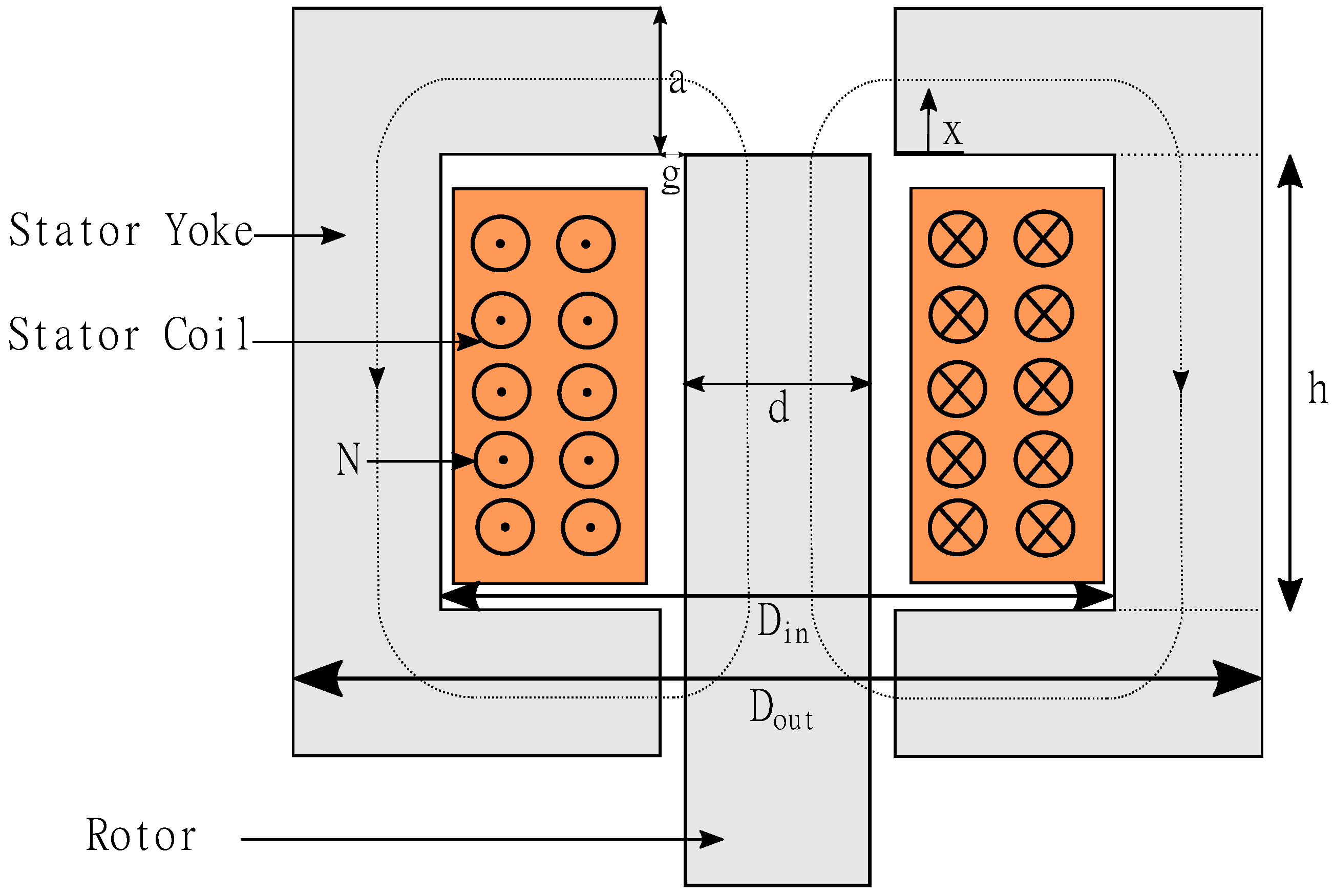
2.2. Electromagnetic Design

The basic electromagnetic actuator consists of an iron rotor pulled inside a stator yoke as illustrated in Figure 2, i.e., solenoid or reluctance type or moving iron actuator. When an input current is applied to the coil wrapped around the central axis, an electromagnetic force is generated to reduce the reluctance of the flux path (indicated with a dashed line in Figure 2).

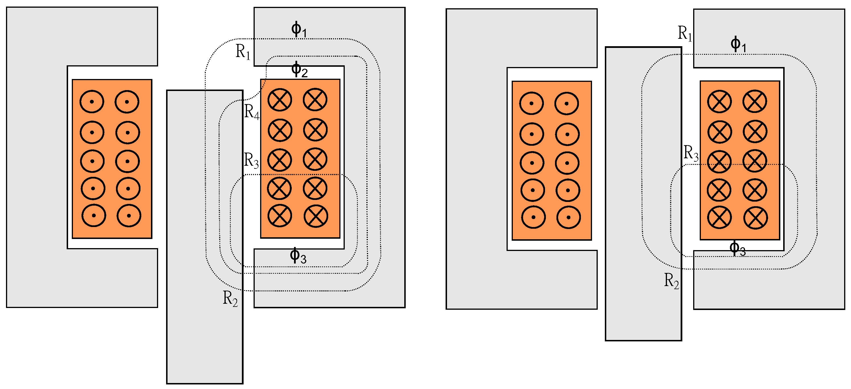
2.2.1. Analytical Model

The key to understanding the force (F) generation principle of a reluctance-type actuator, is thus the change in reluctance R with respect to the position x (Figure 2). Equation (2) (derived in [44] and extended here by including several leakage flux paths) proves the quadratic relationship between the force and input current and that in the vicinity of x = 0 mm the maximum force is expected as the air gap (and its associated reluctance) suddenly decreases when entering the tooth. In other words, pinpointing the main reluctances of a flux path as a function of the geometric parameters (Figure 2), allows to characterise the force generation of an electromagnet:
F = N 2 i 2 2 d d x 1 R ( x , g , d , D i n , D o u t , a , N ) .
Furthermore, the flux linkages λ and associated inductances L ( x ) can be computed for the dynamical equations detailed in Section 3.1:
λ = L ( x ) i = N 2 R ( x ) i
Therefore, the main reluctances have been identified as a function of the geometrical parameters and two separate configurations can be distinguished as illustrated in Figure 3:
  • the left configuration corresponds to x < 0 and illustrates three main flux paths ϕ 1 , ϕ 2 and ϕ 3 ;
  • the right configuration corresponds to x > 0 and simplifies to two main flux paths ϕ 1 and ϕ 3 .
The precise mathematical calculation of the reluctance of flux paths through air is a practical impossibility as flux usually does not confine itself to any particular path which has a simple mathematical law. Therefore, the flux paths have been simplified by the ones illustrated in Figure 3 by keeping in mind that the flux paths in air between any two surfaces will always arrange themselves such that a maximum possible flux will be produced for a given magnetomotive force (as a result of a current flowing through a coil or produced by a permanent magnet) [45].
The calculation of the reluctances, defined in Figure 3 and Equation (2), can be reduced to straightforward mathematical formulations, as detailed in [45]. The idea is thus to evaluate an actuator based on the power required to fit the electromagnetic force profiles on the gas forces of the RCK-1. To illustrate its operation, the geometrical parameters of an existing solenoid prototype (Table 2), further used to validate the analytical and FEM-models, are implemented in the model and verified against a generic gas force profile representing the compression requirements of the RCK-1, as illustrated in Figure 4. The idea is then to derive the required current-profile based on the intersections between the electromagnetic force and gas force profiles. Based on Figure 4, a maximum current of 4 A seems sufficient to drive the compression. The validation of the analytical model is discussed in detail in the following section.

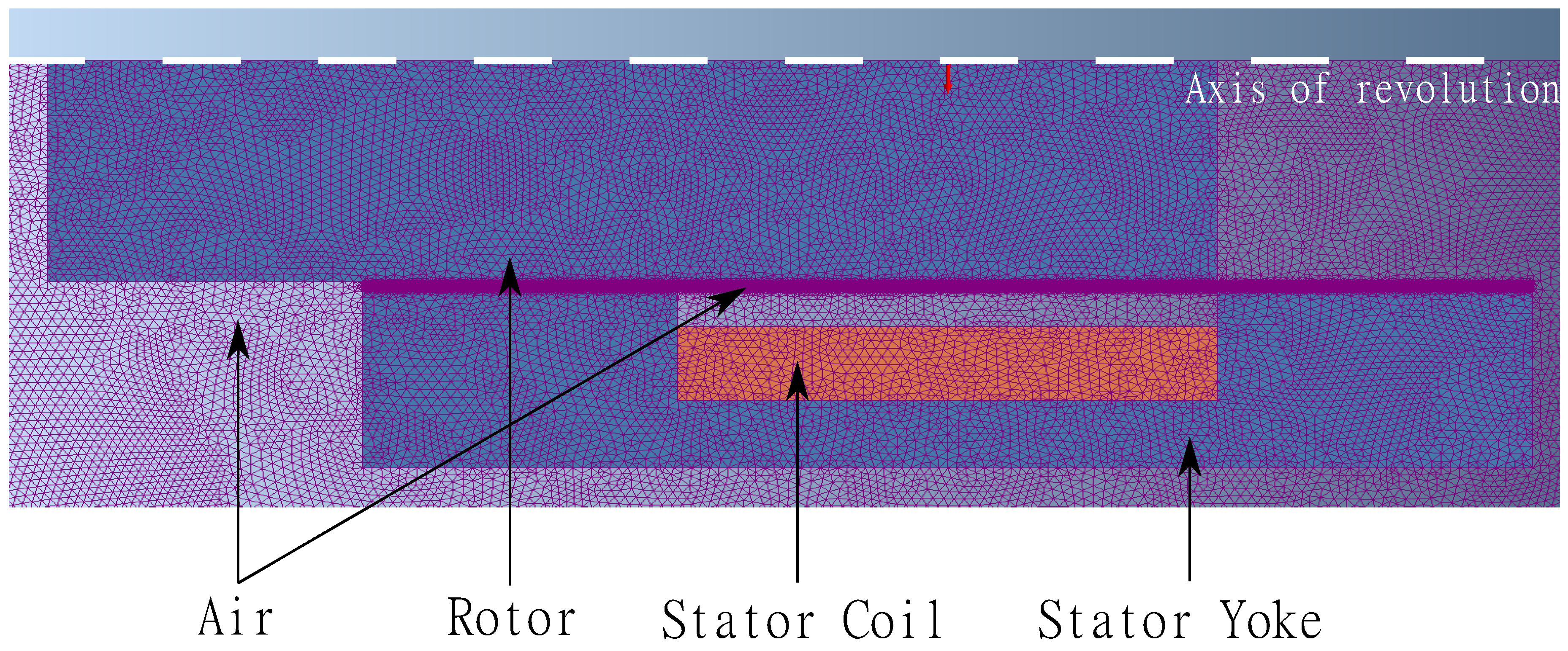
2.2.2. Finite Element Method

The analytic derivation of the electromagnetic force provides the necessary insights regarding the working principle of an electromagnetic actuator in the first step of the optimisation process. Unfortunately, the strategy has its limits, as magnetic materials in general are nonlinear and the magnetic permeability changes with the magnetisation H and the magnetic flux density B. Therefore, a Finite Element Method (FEM), using Mentor MagNet, is adopted in a second step of the optimisation. MagNet is a FEM simulation software used worldwide for the design of motors, sensors, transformers, actuators, solenoids or any component with permanent magnets or coils. It allows to incorporate different nonlinear effects, such as saturation, in the design of a linear electromagnetic compressor. For this, a set of static simulations have been performed using a Matlab script governing the FEM software for the different axial positions and currents. This allowed to parameterise the design and to loop over the different parameters to optimise the actuator.
For the stator yoke and rotor, cold-rolled steel CR10 has been considered with a B H -curve, as illustrated in blue in Figure 5. For the electric coil, N (one of the parameters to be optimised) windings of copper have been selected. The cylinder symmetry of the design allows for the simulation of the complete geometry in a 2D axis-symmetric space dimension surrounded by an air box. A maximum element size of 1 mm has been selected for the different components and a local mesh refinement up to an element size of one-tenth of the air gap thickness g has been implemented in the small air gap between the stator and the rotor to minimise the discretisation error in the parts of interest. This implementation allows to significantly increase the accuracy with a minimal increase in computation time. The agreement between finite element and experimental results has been detailed in the following section. An illustration of the meshed geometry is presented in Figure 6.

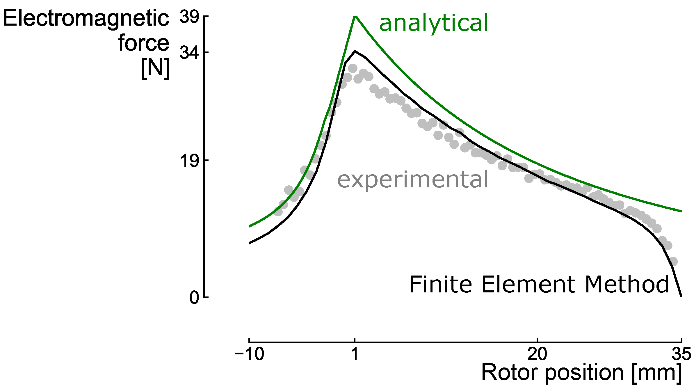
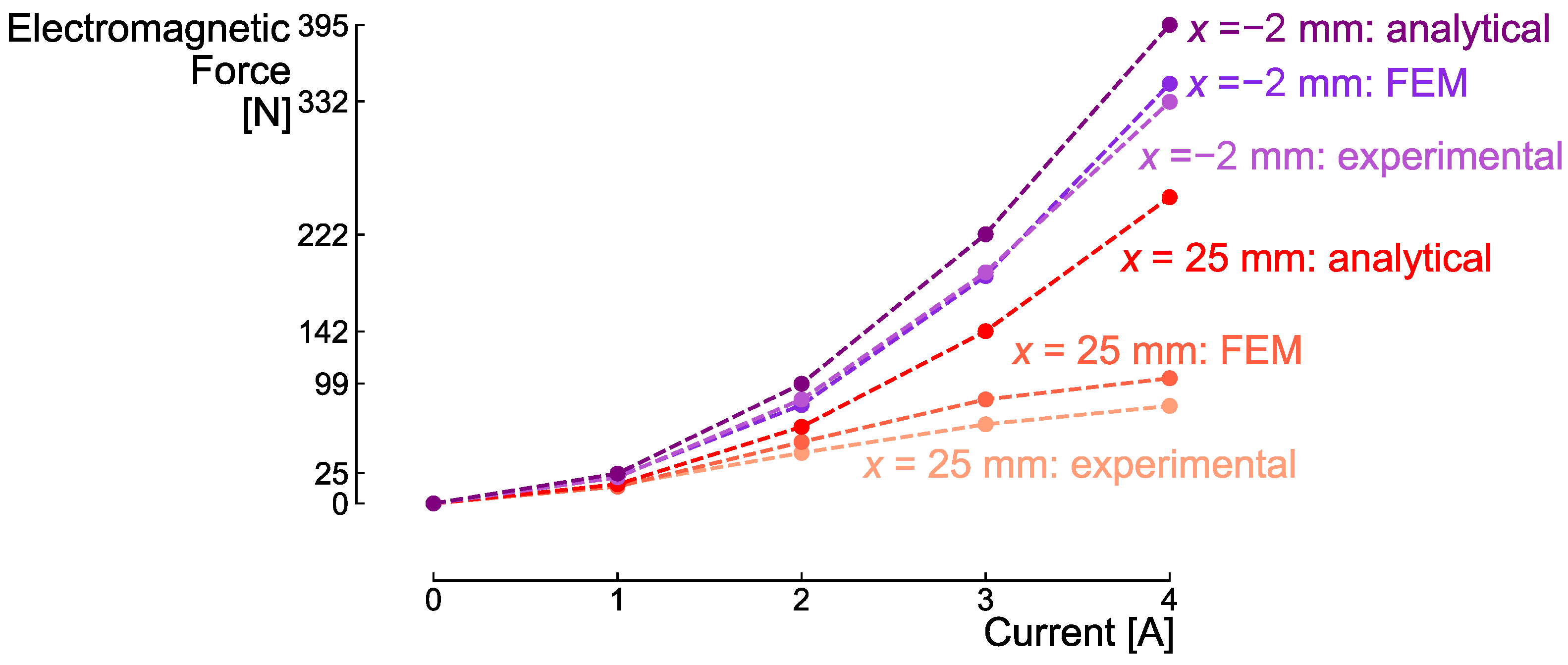
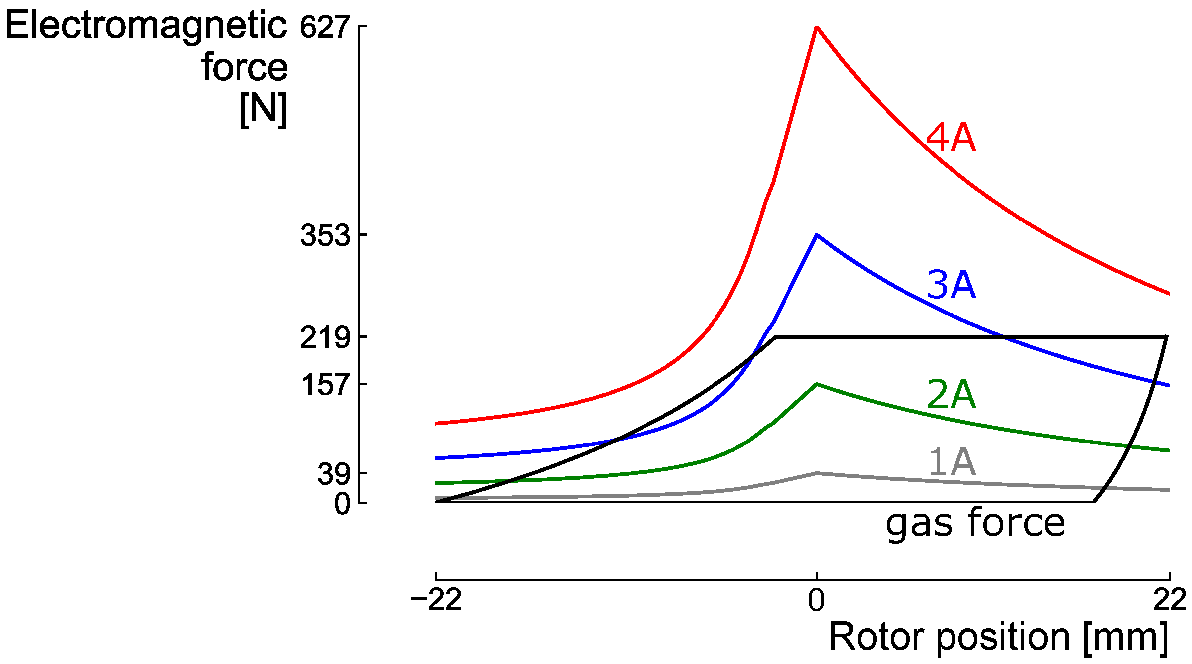
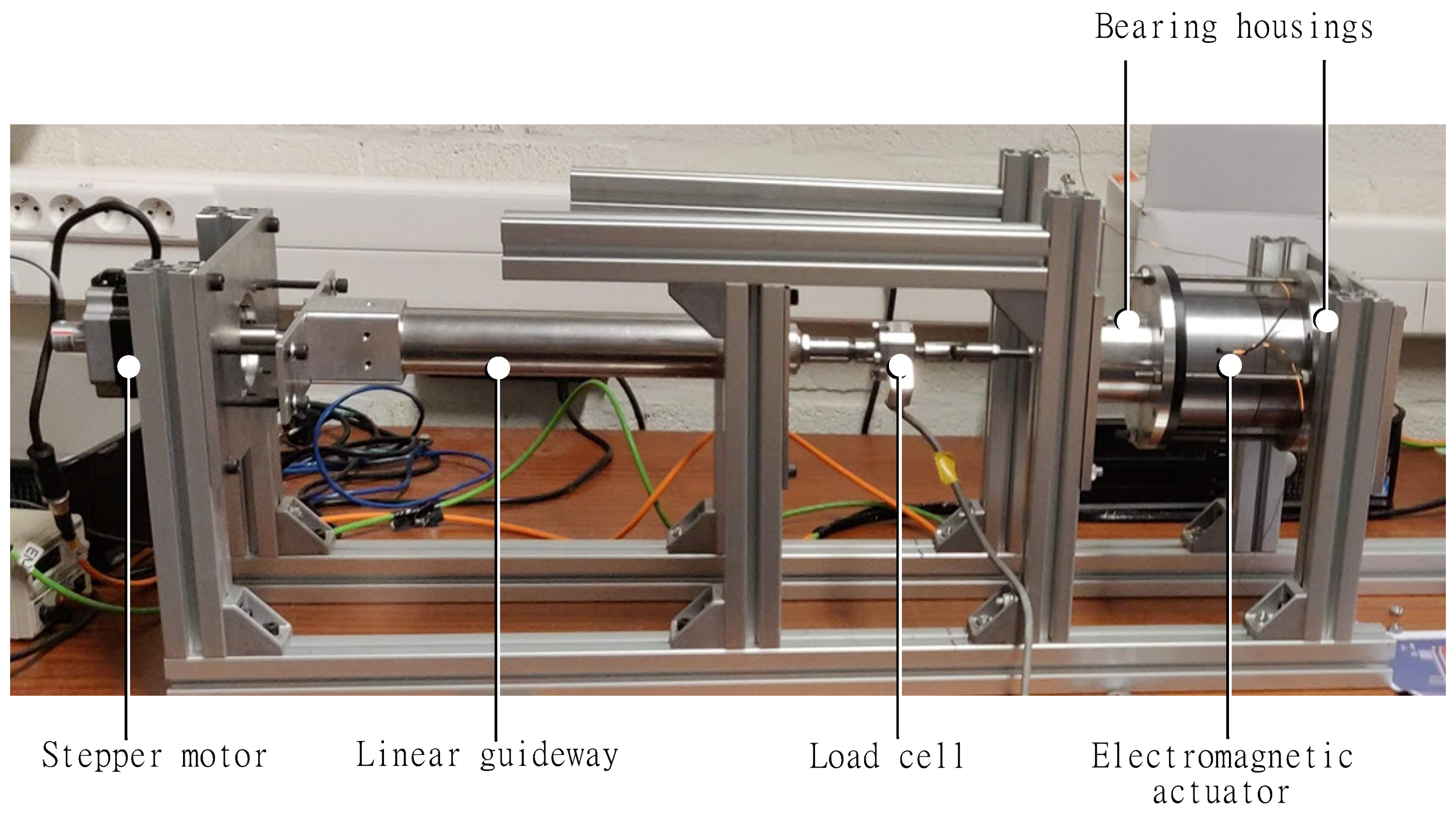
2.2.3. Model Validation

An analytically designed electromagnetic actuator has been developed, including some accessories, to validate the analytical and finite element model. The experimental set-up is highlighted in Figure 7. The prototype itself consists of a plunger and stator yoke in cold-rolled steel CR10 and the windings consist of enamelled copper (AWG 21) wound around a 3D-printed holder. The plunger itself is supported by two bearing housings in aluminium to avoid any radial misalignment and to minimise the friction forces in the actuator. The stepwise rotative motion of a stepper motor is converted into a linear motion by a linear guideway allowing to accurately impose the axial position of the plunger w.r.t. the stator. A force transducer (HBM U9C) is implemented between the plunger and the linear guideway to measure the forces acting on the rotor, while the current is provided to the coil by a 0–60 V range DC power supply. A Beckhoff-module is used to control the stepper motor and capture the forces and axial position of the electromagnetic actuator, where a rotation of 1.8 of the stepper motor is imposed per step, which results in a shift of 0.1 mm in the axial position. An acquisition time of 10 ms is chosen before performing another rotation to obtain a steady state configuration. This allows us to ignore the dynamic effects associated to any flux changes in the system.
Figure 8 highlights the agreement between the analytical, finite element and experimental results for a solenoid actuator with parameters highlighted in Table 2 (with a small input current of 1 A to make sure no saturation effects occur). In Figure 9, the upper three curves demonstrate the quadratic relationship between the applied current and electromagnetic force as previously explained with Equation (2).
However, the discrepancy between the analytical on the one hand and the finite element and experimental results on the other hand for higher currents at rotor position x = 25 mm in Figure 9, proves the limitations of the analytical formulations where saturation is not considered. This results in a limitation of the output force at higher currents, justifying the finite element procedure followed in a second step of the optimisation.

3. Design Optimisation

Following the description of the actuator models in previous section, this section provides the design parameters, constraints and objective functions, which define the design optimisation case. To acquire the optimised designs, this section ends with the underlying optimisation algorithm and the multi-fidelity optimisation approach.

3.1. Design Parameters

Based on the analytical model, the most dominant parameters (and their corresponding ranges) of the electromagnetic actuator can be distinguished. The number of windings N and the current i both have a quadratic relation with the force F (Equation (2)). However, increasing the number of windings quadratically increases the back-electromotive force d λ d t (back-emf) of the system and therefore lowers the maximum available current (and thus force) of the system [44]:
V = R i + d λ d x d x d t ,
with V the voltage, R the static resistance, L the inductance and λ the flux-linkage of the system. Therefore, the number of windings is limited to 1000 turns. A second way to optimise the force is by maximising the change in reluctance d 1 R ( x ) d x , which is mainly characterised by the air gap between the stator and the rotor. Therefore, as saturation is considered, the geometry of rotor and stator is included in the design process. To make sure the geometric constraints are complied with, the ranges of the air gap, the plunger diameter, the diameter of the rotor and the inner diameter are defined relatively with respect to each other:
g < d < D in < D out .
Finally, the tooth length a is incorporated to make sure the gas forces can be complied with during the full stroke of the compressor. Conclusively, the design parameters (illustrated in Figure 2) and their corresponding ranges considered in the optimisation algorithm are presented in Table 3.
For each design evaluation, two additional degrees of freedom are present. The first degree of freedom is the operating current, which is evaluated incrementally between 0 A and 10 A. The lowest current that satisfies the compression requirements is selected as operating current for a specific design. The second degree of freedom relates to the piston position and relative rotor displacement. The sudden reluctance change when the rotor enters the tooth can be placed adequately with respect to the gas forces, to optimally benefit from its associated force peak (Figure 8). In other words, the relationship between the piston position x p and relative displacement of the rotor x is selected for each design evaluation:
x p = x peak + x .
Therefore, when evaluating a design with respect to the compressor requirements, different values of x peak are evaluated to find the optimal relationship between the piston position x p and the position of the rotor x. The concept is illustrated in Figure 10, where the same electromagnetic force-displacement profile (i.e., same input current) is shifted with respect to the gas forces. In the particular case in Figure 10, the blue curve (piston position is 34 mm) illustrates the correct relative position between piston and actuator to make sure the gas forces can be compensated with that particular minimal current.

3.2. Constraints

Next to the degrees of freedom illustrated in the previous section, electrodynamic constraints need to be complied with, in order to achieve a feasible design. An obvious constraint is that the design needs to comply with the gas forces, which are modelled using an isentropic compression. Therefore, a decrease in volume V in the compression chamber results in an increase in pressure P:
P V γ = constant ,
assuming a constant heat capacity ratio γ = C p C v . The theoretical P-V diagram of the crank-driven reciprocating compressor RCK-1 for a nominal outlet pressure of 2.07 bar [40] is converted into a force–displacement relationship (Figure 10).
The flux change with respect to the coil results in a counteracting voltage in that coil. Therefore, the movement of the rotor with respect to the stator results in a back-emf in the coils, which limits the maximum available current (and thus force) of the electromagnetic actuator (Equation (4)). Considering the flow requirements of the RCK-1 and the available voltage sources (TDK-Lambda: Z+600 Series) in the lab, a maximum voltage of 60 V , a maximum current of 10 A and a maximum velocity d x d t of 0.25 m / s are considered. To evaluate if the constraint on the voltage V is complied with, d λ d x is calculated analytically in case of the analytic model, or by numerical differentiation in case of the FEM. Based on the maximum current available (to avoid future heat issues), an American Wire Gauge 18-cable is selected. As a result, the static resistance R is calculated based the length and cross section of the copper wire required to obtain the number of windings, considering a fill factor of 0.7 [46]. An alternative could be to determine the winding window and determine the amount of windings for a given voltage, from which the wire diameter can be calculated.

3.3. Objective Functions

To determine the performance of the evaluated designs, minimising the peak power requirement and minimising the copper volume are selected as objectives. While the peak power requirement correlates with the total power consumed of the system, the copper volume reflects the dominant factor in the electromagnetic actuator price and is related to the overall dimensions, i.e., footprint, of the actuator as well. The copper volume V Cu is directly related to the number of windings:
V Cu = N π 2 D in + d D cable 2 8 .
The peak power required is determined by the maximum current supplied during the stroke I max and the corresponding voltage V max :
P peak = V I max .
Both objectives suggest an inversely proportional relation: When the number of windings (and thus copper volume) increases, the required current (and thus power) reduces. However, increasing the number of windings increases the back-emf, which induces an increase in voltage. Furthermore, when evaluating Equation (2), the input current is an important parameter for the electromagnetic force generation, determining the compliance of a design with respect to the constraints. Therefore, determining the optimised designs is not straightforward, and therefore these objectives are selected in the optimisation algorithm.

3.4. Multi-Fidelity Optimisation Approach

To obtain the optimal electromagnetic performance, the design parameters need to be characterised simultaneously. For this system, the system performance is determined by the minimal peak power and copper volume required to overcome the gas forces. As a trade-off exists between minimising the peak power and minimising the copper volume, a Pareto set of designs exists, where each design dominates every other design in one objective. In this work, the Nondominated Sorting Genetic Algorithm (NSGA-II) is applied to characterise this Pareto set of designs [29,47]. The optimisation algorithm starts with a population size of 60 design samples, based on a rule of thumb of 10 samples per design parameter [48], and the algorithm is characterised with a crossover probability of 0.9. The mutation probability is set at 0.1, which is higher than typical mutation probability values [49], to avoid local minima in subsequent steps in the multi-fidelity optimisation approach.
During a design optimisation, the configuration of the next population requires information from the fully evaluated previous population, which essentially limits the parallel processing of evaluations up to the size of a single population. Therefore, a complete design optimisation is computationally expensive. To improve the computational efficiency, we applied a 3-step multi-fidelity optimisation approach, which characterises the design trends based on model evaluations with low CPU time (i.e., handful of seconds) and uses this information to construct an optimised design space for the FEM design optimisation (Figure 11). In the first step, the design optimisation is performed on an analytical model with low CPU time, with a current ranging from 0 A to 10 A, evaluated in fine steps of 0.25 A. As this analytical model does not include saturation effects and tends to overestimate the force of an actuator, the resulting peak power and volume are not achievable in reality and therefore too optimistic. However, the provided minimum peak power (and thus current) illustrates that no fine evaluation of the current is required below this minimum current, as the final optimised design will achieve a current above this minimum current due to saturation. Moreover, the minimum volume illustrates that any design generated in the next optimisation steps with a volume below this minimum volume can be discarded. Both interventions (i.e., no evaluation of low current profiles and discarding designs with low copper volume) lead to a significant increase in computational efficiency of the FEM design optimisation, without losing potential optimised design configurations.
In the second step, the FEM is evaluated in the optimisation process, with a current ranging from the minimum current (defined during the analytical optimisation) up to 10 A, evaluated in coarse steps of 1 A. Following this coarse designs, the third step of the optimisation is performed on the FEM, with a fine current evaluation in steps of 0.25 A in the resulting current range. Therefore, the fine evaluation of the current is focused on the region where the optimised designs will occur, based on the information from the analytical and coarse optimisation, while discarding small volumes before the FEM to further improve the computational efficiency. Based on a sensitivity analysis of the analytical model, 75 generations are considered for the FEM optimisation. This fixed computational budget is allocated equally over the second and third optimisation step, which balances the importance of design space exploration and design refinement. An imbalance in the allocation of the computational budget might lead to different solutions, but similar trends in the design parameters are expected.

4. Results

This section illustrates the results achieved during every step of the multi-fidelity optimisation procedure. At the first step, the peak power and volume lower limit are defined, followed by the initial coarse optimisation. Finally, the fine optimisation provides the characteristics of the set of optimised designs.

4.1. First Step: Optimisation of Analytical Model

Despite the lack of saturation characteristics in the analytical model, applying the multi-objective optimisation algorithm on this model reveals a Pareto set of optimised designs, which identifies the trade-off between minimising the peak power and minimising the copper volume. While the optimised peak power and volume on the analytic model are too optimistic, these minima also provide valuable information to narrow down the computational cost for the next optimisation steps. In this first step, a population of 60 designs is evaluated over 100 generations to achieve convergence. As the analytic model is quickly evaluated (few seconds) and the evaluations can be performed in parallel over the number of available processors, the computational cost for this step is negligible compared to the next optimisation steps.
The optimisation of the analytic model identifies a minimum achievable copper volume of 40.4 cm 3 at a peak power of 285.9 W , whereas the minimum peak power of 199.2 W is achieved at 95.0 cm 3 (Figure 12). The design that achieves the minimum peak power achieves the minimum required current as well (i.e., 4.0 A). As the analytic model generates results that are too optimistic, the optimised performance design, in reality, will perform at a current higher than 4.0 A, while the real design with the smallest copper volume will attain a copper volume larger than 40.4 cm 3 , as nonlinear effects such as saturation are not taken into account. This information is further used in the second optimisation step to reduce the number of current evaluations and discard small copper volumes before the computationally expensive FEM initiates.

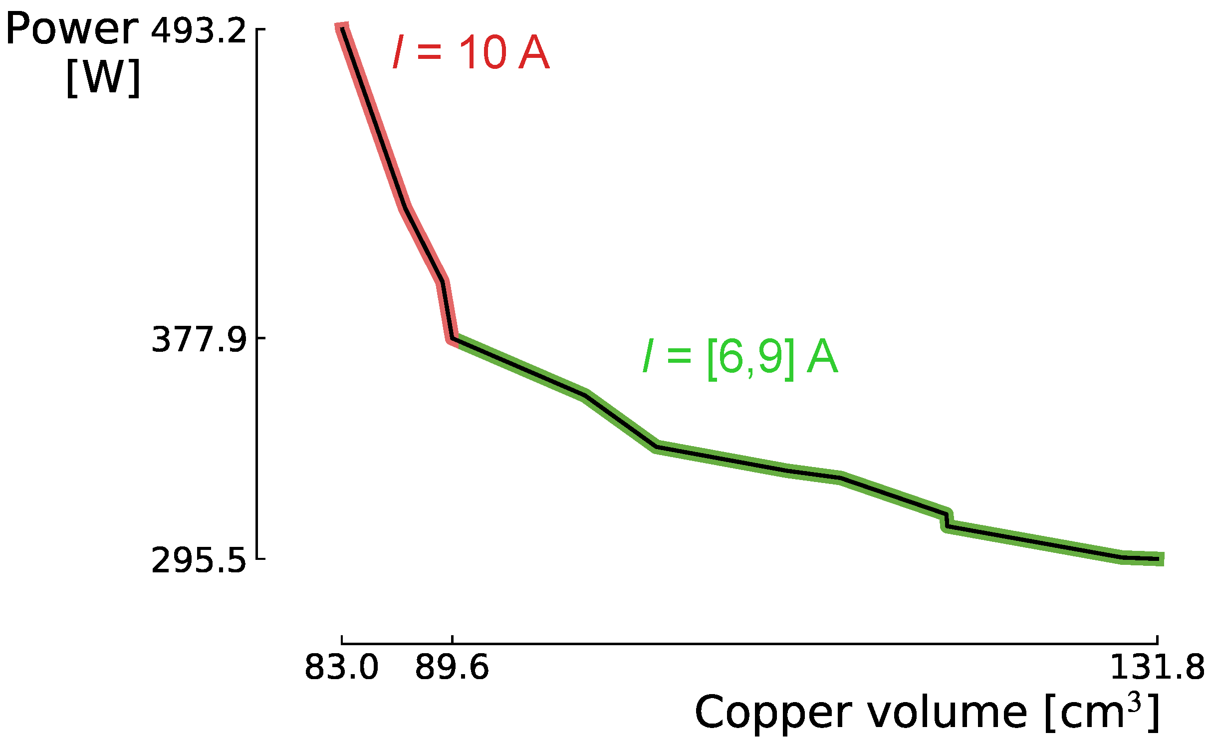
4.2. Second Step: Coarse Optimisation

In the second optimisation step, a coarse optimisation is performed on the FEM. For every model evaluation, different current profiles are evaluated to determine the minimum required operating current for that design. Based on the results of the analytic optimisation, the number of evaluated currents can be reduced, without loss of viable solutions. The lowest current profile is set at 4 A, as the analytic optimised results indicate that no feasible design can be constructed that achieves a minimum current of 4.0 A or less. Therefore, for every model evaluation, seven current profiles are evaluated (ranging between 4 A and 10 A), as opposed to 10 current profiles, which reduces the computational cost by 30%. Moreover, initial design configurations with a copper volume < 40.4 cm 3 are discarded before the FEM initiates. A fixed computational budget of 3 days is allocated to this second optimisation step, resulting in 50 generations for a population of 18 samples (i.e., 10 min per model evaluation). The optimised designs illustrate again the trade-off between minimising the peak power and copper volume, with a minimum required peak power of 295.5 W at a copper volume of 131.8 cm 3 , while the minimum copper volume of 83.0 cm 3 is achieved at a peak power of 493.2 W (Figure 13). The designs which require a relative high peak power (i.e., between 377.9 W and 493.2 W ) operate with a current of 10 A, while the other designs (with lower power requirements) operate between 6 A and 9 A. Hence, 58% of the resulting peak power range is determined by designs operating at 10 A, while the corresponding copper volume range (i.e., between 83.0 cm 3 and 89.6 cm 3 ) composes only 13% of the copper volume range of the optimised designs. Consequently, this set of designs illustrate that in their peak power and volume range, a large power increase is required to gain a marginal decrease in copper volume. Moreover, as these designs operate at the current upper limit, their feasibility is sensitive to uncertainty during design and operation. This allows to shift the focus towards the lower current designs in the third step of the optimisation, where the current range of interest will be more finely evaluated.

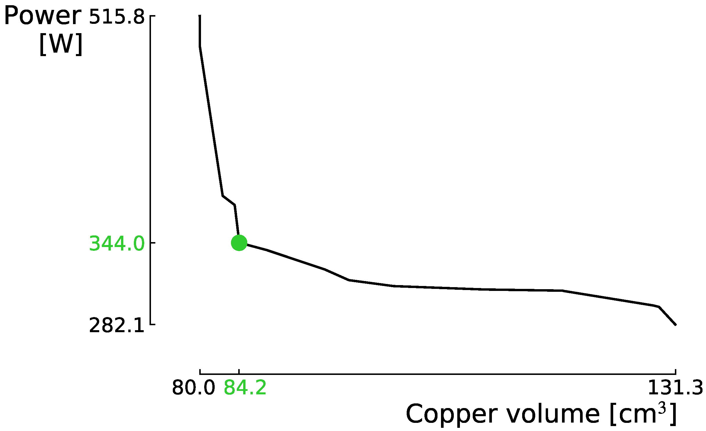
4.3. Third Step: Fine Optimisation
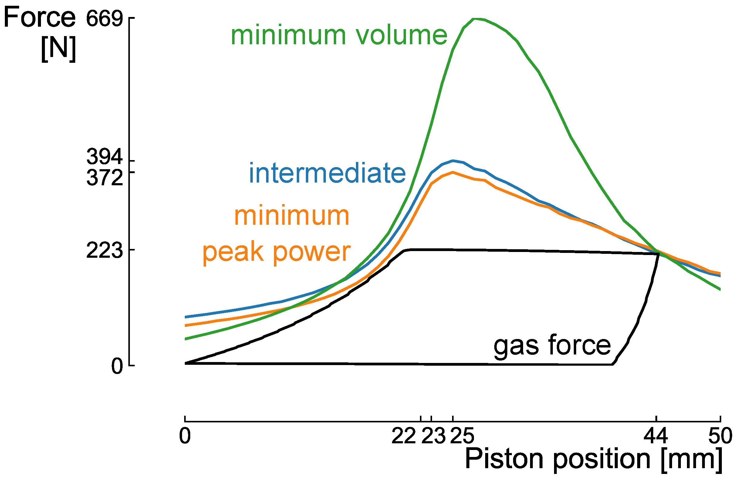
Based on the information from the two previous optimisation steps, the fine optimisation procedure is configured to provide the final optimised designs. The fine optimisation considers current profiles between 5.25 A and 9.0 A in steps of 0.25 A. Moreover, 10 A is evaluated as well to cover the entire trade-off, while any volume < 83.0 cm 3 is discarded ahead of the expensive FEM. The optimisation continues with the designs provided during the coarse optimisation, which improves the computational efficiency of the method. When evaluating an additional 25 generations, the computational cost of the entire method (i.e., seven current evaluations for a population of 18 over 50 generations in step 2, plus 17 current evaluations for a population of 18 over 25 generations in step 3) is reduced by 74% as opposed to an entire fine optimisation procedure between 0 A and 10 A (i.e., 40 current evaluations for a population of 18 over 75 generations). In the quantification of the computational efficiency, the set-up time and the optimisation time of the analytical model is not considered, due to modest complexity of the analytical model and the significantly lower evaluation time (and ability to perform parallel processing) of the analytical model as opposed to the FEM, i.e., 1 × 10 2 times lower, respectively.
The Pareto front illustrates the trade-off between minimising the peak power and minimising the copper volume (Figure 14), as demonstrated by the coarse optimisation (Figure 13). Following the fine evaluation of the current in the considered design region, a design with a lower minimum peak power is determined during the fine optimisation ( 282.1 W at 5.5 A) as opposed to the minimum peak power achieved during the coarse optimisation ( 295.5 W at 6 A). Moreover, due to the additional generations, the minimum acquired copper volume is improved as well (from 83.0 cm 3 in the coarse optimisation, down to 80.0 cm 3 in the fine optimisation). An intermediate alternative is highlighted, operating at 344.0 W with a copper volume of 84.2 cm 3 (Table 4). When comparing with the design achieving the minimum copper volume, on one hand, this intermediate alternative operates at 33.3% lower peak power, while the copper volume is increased by only 5.3%. On the other hand, when comparing with the design achieving the minimum peak power, the intermediate alternative achieves a 39.1% copper volume reduction, while the operating peak power is increased by 21.9%.

4.4. Discussion

The Pareto front in Figure 14 will be detailed using the three designs highlighted in Table 4. When evaluating the evolution of different optimisation parameters one by one, a few particular trends can be noticed. To explain these, an extremely simplified analytical equation can be used, detailed in [44], for the solenoid actuator (and its corresponding parameters):
F = i 2 2 μ 0 π a 2 d N 2 g ( a + x ) 2
When comparing the second and third design of Table 4, the trade-off between the amount of windings N and the current i is clear: The increase in the amount of windings results in a smaller current required to provide the same force (Equation (10)), which decreases the peak power of the actuator. However, this advantage is constrained. The quadratic relationship between N and the back-emf, as detailed in Section 3.1, limits the maximum available current with a certain voltage supply. Furthermore, it results in an increase of the resistance of the coil, which further limits this maximum available current.
The first geometric parameter is the tooth length a, which determines the width of the force peak illustrated in Figure 8. When evaluating Equation (10), the ratio a 2 ( a + x ) 2 influences the force generation of the actuator. In other words, as x denotes the relative position of the rotor with respect to the tooth, and as the range of x is fixed due to the stroke of the compressor, a larger a will result in an increase of that particular ratio. Keeping x small compared to the tooth length means physically staying in the region where the sudden change in reluctance takes place, making sure sufficient force can be provided over the full stroke.
As mentioned in the Section 3.1, the inner and outer diameter ( D i n and D o u t ) of the actuator play a small role in the force generation. Nevertheless, they were incorporated to cope with saturation issues and to scale alongside the other parameters, in order to provide the required volume for the windings.
The last two geometric parameters, the rotor diameter d and the air gap thickness g, seem to go hand in hand based on Equation (10). However, an increase of both parameters when comparing the first two designs of Table 4, unexpectedly resulted in a lower current with a decrease of the number of windings N. The decrease of the reluctance by increasing the diameter d, seems to be larger than the increase of reluctance by increasing the air gap thickness g, resulting in a lower current required to drive the compression.
Evaluating Table 4 (and Figure 14), keeping in mind both constraints, the first design is not desired due to its extremely large peak power for a rather small reduction of the volume of copper as opposed to the second design. In this case, the design with a lower peak power is preferred, as the thermal aspect of the actuator is not considered in this design optimisation. Therefore, the optimal design lies somewhere in the range of the breaking point, where a small decrease in copper volume does not result in a large increase in required peak power. The selected optimal designs are plotted on the compression requirements in Figure 15, indicated by their input current. The resulting control strategy will thus consist of the intersections between the different electromagnetic force profiles and the gas forces. When focusing on the force profiles of the three selected designs, the intermediate and minimal power designs have a similar trend as the analytical profiles detailed in Figure 4 and Figure 8, which indicates that these designs operate in linear, non-saturated conditions. However, the minimal volume design illustrates a large force peak, followed by a steep force drop, as saturation occurs due to the minimal volume (resulting in smaller surfaces) and higher currents (resulting in an increased flux). For the sake of completeness, the final geometries are drawn in the CAD-software Inventor in Figure 16.

5. Conclusions

This paper described the design optimisation and analysis of a solenoid actuator for a long stroke linear compressor by means of a multi-objective, multi-fidelity optimisation algorithm, which takes advantage of the speed and accuracy of the analytical model and Finite Element Method, respectively. Both the analytical and finite element model were experimentally validated and showed a good agreement (errors within 10%) with the experimental results. The computational cost of the proposed optimisation approach was reduced by 74%, as opposed to an entire fine Finite Element Method optimisation. The optimisation objective was to minimise the operating peak power and the copper volume, subject to the constraint of fitting the electromagnetic force-profiles on the compression requirements of a reciprocating air compressor. The results illustrate a clear trade-off between minimising the peak power and volume, resulting in an optimal performance design which achieves 282.1 W and 131.3 cm 3 , while the smallest copper volume of 80.0 cm 3 is achieved at a peak power of 515.8 W . Taking into account this trade-off, an intermediate design is highlighted (peak power of 344.0 W at a copper volume of 84.2 cm 3 ). The trade-off between the number of windings N and input current i remains a dominant design characteristic; nevertheless, the power requirements of the actuator can be decreased drastically by cleverly adapting the geometric parameters. This analysis and optimisation strategy allows investigating more complex linear electromagnetic actuator geometries required for higher power application in future work, where permanent magnets will have to be included to cope with the higher forces and velocities. The use of an optimised permanent magnet design might furthermore remove the necessity of a spring to guarantee the reciprocating motion of the linear compressor.

Author Contributions

J.B. established the analytical and finite element model and designed and performed the experiments to validate them. J.B. and D.C. contributed equally to the optimisation strategy and analysis of the data as well as the writing of the paper. F.C., W.D.P., J.V.M. and B.V. supervised the project. All authors read and agreed to the published version of the manuscript.

Funding

This research is funded by Flanders Innovation & Entrepreneurship Agency (VLAIO) Baekeland-mandate HBC.2018.2055 and Fonds de la Recherche Scientifique - FNRS (33856455-5001419F FRIA-B1).

Acknowledgments

Flanders Innovation & Entrepreneurship Agency (VLAIO) is gratefully acknowledged for its support within the Baekeland-mandate HBC.2018.2055. Furthermore, we acknowledge Flanders Make for the support of our team. The second author acknowledges the support of Fonds de la Recherche Scientifique - FNRS (33856455-5001419F FRIA-B1).

Conflicts of Interest

The authors declare no conflict of interest. The founding sponsors had no role in the design of the study; in the collection, analyses, or interpretation of data; in the writing of the manuscript, and in the decision to publish the results.

References

  1. Hawken, P. Drawdown: The Most Comprehensive Plan Ever Proposed to Reverse Global Warming; Penguin Books: New York, NY, USA, 2017. [Google Scholar]
  2. Liang, K.; Stone, R.; Hancock, W.; Dadd, M.; Bailey, P. Comparison between a Crank-drive Reciprocating Compressor and a Novel Oil-free Linear Compressor. Int. J. Refrig. 2014, 45, 25–34. [Google Scholar] [CrossRef]
  3. Bradshaw, C.; Groll, E.; Garimella, S. Linear compressors for electronics cooling: Energy recovery and the useful benefits. In Proceedings of the International Compressor Engineering Conference, West Lafayette, IN, USA, 16–19 July 2012. [Google Scholar]
  4. Ku, B.; Park, J.; Hwang, Y.; Lee, J. Performance evaluation of the energy efficiency of crank-driven compressor and linear compressor for a household refrigerator. In Proceedings of the International Compressor Engineering Conference, West Lafayette, IN, USA, 12–15 July 2010. [Google Scholar]
  5. Bailey, P.; Dadd, M.; Stone, C. An oil-free linear compressor for use with compact heat exchangers. In Proceedings of the International Conference on Compressors and their Systems 2009, London, UK, 7–9 September 2009; pp. 259–268. [Google Scholar]
  6. Kim, J.K.; Roh, C.G.; Kim, H.; Jeong, J.H. An experimental and numerical study on an inherent capacity modulated linear compressor for home refrigerators. Int. J. Refrig. 2011, 34, 1415–1423. [Google Scholar] [CrossRef]
  7. Won Sung, J.; Park, J.C.; Kim, G.S.; Won, C.Y.; Choi, S. Sensorless stroke control for linear compressors. Int. J. Appl. Electromagn. Mech. 2005, 24, 604219. [Google Scholar]
  8. Yang, S.B. Output Control Apparatus for Linear Compressor and Method of the Same. U.S. Patent US6176683B1, 6 April 1999. [Google Scholar]
  9. Hahn, G.W.; Kusumba, S.; Mcintyre, M.L.; Latham, J.W. Method for Operating a Linear Compressor. U.S. Patent US20180187674, 13 February 2018. [Google Scholar]
  10. Oh, K.T.; Kim, J.W. Apparatus for Controlling Linear Compressor and Method Thereof. U.S. Patent US6289680B1, 4 November 1999. [Google Scholar]
  11. Latham, J.; McIntyre, M.L.; Mohebbi, M. Sensorless Resonance Tracking and Stroke Control of a Linear Vapor Compressor Via Nonlinear Observers. IEEE Trans. Ind. Electron. 2018, 65, 3720–3729. [Google Scholar] [CrossRef]
  12. Chun, T.W.; Ann, J.R.; Yoo, J.Y.; Lee, C.W. Analysis and control for linear compressor system driven by PWM inverter. In Proceedings of the 30th Annual Conference of IEEE Industrial Electronics Society, Busan, Korea, 2–6 November 2004; pp. 263–267. [Google Scholar]
  13. Otaibi, Z.A. Spring-Less Buried Magnet Linear-Resonant Motor. U.S. Patent US9350221B2, 15 April 2011. [Google Scholar]
  14. Otaibi, Z.A. Spring-less permanent magnet linear-resonant motor for compressor applications. In Proceedings of the IEEE International Conference on Power and Energy (PECon), Kota Kinabalu, Malaysia, 2–5 December 2012. [Google Scholar]
  15. Poltschak, F.; Ebetshuber, P. Design of Integrated Magnetic Springs for Linear Oscillatory Actuators. IEEE Trans. Ind. Appl. 2018, 54, 2185–2192. [Google Scholar] [CrossRef]
  16. Jiang, H.; Liang, K.; Li, Z. Characteristics of a novel moving magnet linear motor for linear compressor. Mech. Syst. Signal Process. 2019, 121, 828–840. [Google Scholar] [CrossRef]
  17. Redlich, R.; Unger, R.; der Walt, N. Linear compressors: Motor configuration, modulation and systems. In Proceedings of the International Compressor Engineering Conference, West Lafayette, IN, USA, 23–26 July 1996. [Google Scholar]
  18. Cadman, R.V.; Cohen, R. Electrodynamic Oscillating Compressors: Part 1—Design Based on Linearized Loads. J. Basic Eng. 1969, 91, 656–663. [Google Scholar] [CrossRef]
  19. Cadman, R.V.; Cohen, R. Electrodynamic Oscillating Compressors: Part 2—Evaluation of Specific Designs for Gas Loads. J. Basic Eng. 1969, 91, 664–670. [Google Scholar] [CrossRef]
  20. Dainez, P.; Oliveira, J.; Nied, A.; Santos Matos Cavalca, M. A linear resonant compressor model based on a new linearization method of the gas pressure force. Int. J. Refrig. 2014, 48, 201–209. [Google Scholar] [CrossRef]
  21. Jonge, A.D. Analysis and optimisation of a linear motor for the compressor of cryogenic refrigeration. Adv. Cryog. Eng. 1981, 27, 631–640. [Google Scholar]
  22. Pollak, E.; Soedel, W.; Cohen, R.; Friedlaender, F. On the resonance and operational behavior of an oscillating electrodynamic compressor. J. Sound Vib. 1979, 67, 121–133. [Google Scholar] [CrossRef]
  23. Chen, N.; Tang, Y.J.; Wu, Y.N.; Chen, X.; Xu, L. Study on static and dynamic characteristics of moving magnet linear compressors. Cryogenics 2007, 47, 457–467. [Google Scholar] [CrossRef]
  24. Sung, B.; Lee, E.; Lee, J. A design method of solenoid actuator using empirical design coefficients and optimisation technique. In Proceedings of the 2007 IEEE International Electric Machines Drives Conference, Antalya, Turkey, 3–5 May 2007; pp. 279–284. [Google Scholar]
  25. Bijanzad, A.; Hassan, A.; Lazoglu, I. Analysis of solenoid based linear compressor for household refrigerator. Int. J. Refrig. 2017, 74, 116–128. [Google Scholar] [CrossRef]
  26. Tsai, N.C.; Chiang, C.W. Design and analysis of magnetically-drive actuator applied for linear compressor. Mechatronics 2010, 20, 596–603. [Google Scholar] [CrossRef]
  27. Wu, J.; Huang, Y.; Song, Y.; Wu, D. Integrated design of a novel force tracking electro-hydraulic actuator. Mechatronics 2019, 62, 102247. [Google Scholar] [CrossRef]
  28. De Paepe, W.; Coppitters, D.; Abraham, S.; Tsirikoglou, P.; Ghorbaniasl, G.; Contino, F. Robust Operational Optimization of a Typical micro Gas Turbine. Energy Procedia 2019, 158, 5795–5803. [Google Scholar] [CrossRef]
  29. Coppitters, D.; De Paepe, W.; Contino, F. Surrogate-assisted robust design optimisation and global sensitivity analysis of a directly coupled photovoltaic-electrolyzer system under techno-economic uncertainty. Appl. Energy 2019, 248, 310–320. [Google Scholar] [CrossRef]
  30. Verleysen, K.; Coppitters, D.; Parente, A.; De Paepe, W.; Contino, F. How can power-to-ammonia be robust? Optimization of an ammonia synthesis plant powered by a wind turbine considering operational uncertainties. Fuel 2020, 266, 117049. [Google Scholar] [CrossRef]
  31. Rao, J.S.; Tiwari, R. Design optimisation of double-acting hybrid magnetic thrust bearings with control integration using multi-objective evolutionary algorithms. Mechatronics 2009, 19, 945–964. [Google Scholar] [CrossRef]
  32. Lee, S.; Yi, H.; Han, K.; Kim, J.H. Genetic algorithm-based design optimisation of electromagnetic valve actuators in combustion engines. Energies 2015, 8, 13222–13230. [Google Scholar] [CrossRef]
  33. Leati, E.; Poltschak, F.; Scheidl, R. An electromagnetically actuated high frequency oscillation pump. Mechatronics 2017, 47, 233–245. [Google Scholar] [CrossRef]
  34. Ciarella, A.; Tsotskas, C.; Hahn, M.; Werter, N.; De Breuker, R.; Beaverstock, C.; Friswell, M.I.; Yang, Y.; Özgen, S.; Antoniadis, A.; et al. A Multi-Fidelity, Multi-Disciplinary Analysis and Optimization Framework for the Design of Morphing UAV Wing. In Proceedings of the 16th AIAA/ISSMO Multidisciplinary Analysis and Optimization Conference, Dallas, TX, USA, 22–26 June 2015; p. 2326. [Google Scholar]
  35. Reitenbach, S.; Schnoes, M.; Becker, R.G.; Otten, T. Optimization of compressor variable geometry settings using multi-fidelity simulation. In Proceedings of the ASME Turbo Expo 2015: Turbine Technical Conference and Exposition, Montreal, QC, Canada, 15–19 June 2015. [Google Scholar]
  36. Wang, J.; Howe, D.; Lin, Z. Design Optimization of Short-Stroke Single-Phase Tubular Permanent-Magnet Motor for Refrigeration Applications. IEEE Trans. Ind. Electron. 2010, 57, 327–334. [Google Scholar] [CrossRef]
  37. Zhi, L.; Yan, L.; Yuan, Z. Parameters Optimization of Linear Compressor for Refrigerator. Appl. Mech. Mater. 2013, 331, 84–87. [Google Scholar]
  38. Rane, M.V.; Uphade, D.B. Novel Long Stroke Reciprocating Compressor for Energy Efficient Jaggery Making. In Proceedings of the IOP Conference Series: Materials Science and Engineering, London, UK, 11–13 September 2017; Volume 232, p. 012004. [Google Scholar]
  39. Gomis-Bellmunt, O.; Galceran-Arellano, S.; Sudrià-Andreu, A.; Montesinos-Miracle, D.; Campanile, L.F. Linear electromagnetic actuator modeling for optimisation of mechatronic and adaptronic systems. Mechatronics 2007, 17, 153–163. [Google Scholar] [CrossRef]
  40. Bently Nevada. RCK-1 Reciprocating Compressor Simulation Kit, Technical Report. 2015.
  41. Arnold, K.; Stewart, M. Chapter 11—Reciprocating Compressors **Reviewed for the 1999 edition by Lonnie W. Shelton of Paragon Engineering Services, Inc. In Surface Production Operations: Design of Gas-Handling Systems and Facilities, 2nd ed.; Arnold, K., Stewart, M., Eds.; Gulf Professional Publishing: Woburn, MA, USA, 1999; pp. 286–326. [Google Scholar]
  42. Ribas, F.; Deschamps, C.; Fagotti, F.; Morriesen, A.; Dutra, T. Thermal Analysis of Reciprocating Compressors—A Critical Review. In Proceedings of the International Compressor Engineering Conference, West Lafayette, IN, USA, 17–20 July 2006. [Google Scholar]
  43. Choi, B.J.; Jang, C.Y.; Cho, M.S.; Park, S.H.; Kim, H.; Shin, J.M.; Jeon, Y.H.; Roh, C.G. Linear Compressor. U.S. Patent US20090047154A1, 30 August 2004. [Google Scholar]
  44. Fitzgerald, A.E.; Charles Kingsley, J.; Umans, S.D. Electric Machinery; McGraw-Hill Higher Education: New York, NY, USA, 2003. [Google Scholar]
  45. Roters, H.C. Electromagnetic Devices; John Wiley and Sons: New York, NY, USA, 1941. [Google Scholar]
  46. Querfurth, W. Coil Winding: A Description of Coil Winding Procedures, Winding Machines and Associated Equipment; G. Stevens Mfg. Company: Peoria, IL, USA, 1954. [Google Scholar]
  47. Giorgetti, S.; Coppitters, D.; Contino, F.; Paepe, W.D.; Bricteux, L.; Aversano, G.; Parente, A. Surrogate-Assisted Modeling and Robust Optimization of a Micro Gas Turbine Plant With Carbon Capture. J. Eng. Gas Turbines Power 2020, 142, 011010. [Google Scholar] [CrossRef]
  48. Tsirikoglou, P.; Abraham, S.; Contino, F.; Bağci, Ö.; Vierendeels, J.; Ghorbaniasl, G. Comparison of metaheuristics algorithms on robust design optimisation of a plain-fin-tube heat exchanger. In Proceedings of the 18th AIAA/ISSMO Multidisciplinary Analysis and Optimization Conference, Denver, CO, USA, 5 June 2017; p. 3827. [Google Scholar]
  49. Sharma, N.; Anupama, K. On the use of NSGA-II for multi-objective resource allocation in MIMO-OFDMA systems. Wirel. Netw. 2011, 17, 1191–1201. [Google Scholar] [CrossRef]
Figure 1. Conceptual drawing of a linear compressor consisting of an electromagnetic actuator rigidly connected to a piston where x p denotes the position of the piston from Bottom Dead Centre (BDC) to Top Dead Centre (TDC).
Actuators 09 00038 g001
Figure 2. Schematic illustration of a solenoid actuator.
Actuators 09 00038 g002
Figure 3. Conceptual illustration of the main flux paths (and corresponding reluctances) in a solenoid actuator where the left image corresponds to a configuration with x < 0 and the right figure to a configuration for x > 0 .
Actuators 09 00038 g003
Figure 4. Comparison of the analytical results of the solenoid actuator with geometry detailed in Table 2 to the compression requirements of the RCK-1 for multiple input currents. A maximum current between 3 A and 4 A seems sufficient to drive the compression.
Actuators 09 00038 g004
Figure 5. BH curve of cold-rolled steel CR10 in the materials library of Mentor Magnet.
Actuators 09 00038 g005
Figure 6. Axis symmetrical geometry in Mentor Magnet.
Actuators 09 00038 g006
Figure 7. Experimental set-up to measure the static force displacement profiles.
Actuators 09 00038 g007
Figure 8. Comparison between the analytical, finite element and experimental results as a function of the rotor position x for an input current of 1 A for a solenoid actuator with parameters highlighted in Table 2.
Actuators 09 00038 g008
Figure 9. Comparison between the analytical, finite element and experimental results as a function of the current for the axial positions x = −2 mm and x = 25 mm for a solenoid actuator with parameters highlighted in Table 2.
Actuators 09 00038 g009
Figure 10. Illustration of the concept to find the relationship between the piston position x p and relative position of the rotor x for a certain electromagnetic design.
Actuators 09 00038 g010
Figure 11. The scheme of the 3-step optimisation approach illustrates the refinement of the current. At the first step, the analytical model is optimised, resulting in an indication on the minimum current achievable. Then, in the second step, a coarse optimisation is applied on the Finite Element Method (FEM), by evaluating the currents starting from the previously indicated minimum current up to 10 A, in steps of 1 A. This coarse optimisation indicates the current range that relates to the optimised designs of interest. Finally, a fine optimisation is conducted by a fine evaluation of the current in the range of interest.
Actuators 09 00038 g011
Figure 12. The optimised Pareto front of the analytic optimisation illustrates that designs with a copper volume smaller than 40.4 cm 3 and operating below 199.2 W will conflict with the operating constraints in the optimisation of the Finite Element Method (FEM).
Actuators 09 00038 g012
Figure 13. The Pareto front of the coarse optimisation illustrates that a significant part of the optimal peak power range is characterised by designs operating at 10 A.
Actuators 09 00038 g013
Figure 14. The Pareto front of the fine optimisation illustrates that an intermediate design ( 344.0 W and 84.2 cm 3 ) operates at 33.3% lower peak power than the design achieving minimum copper volume, while the copper volume is increased by only 5.3%.
Actuators 09 00038 g014
Figure 15. The electromagnetic force profiles for the designs presented in Table 4 and the compression requirements of the RCK-1.
Actuators 09 00038 g015
Figure 16. CAD-model in Inventor of the 3 design highlighted in Table 4 displaying the final values of the geometric optimisation parameters to give a visual overview of the difference between the 3 designs.
Actuators 09 00038 g016
Table 1. Specifications of the Reciprocating Compressor Kit RCK-1.
Specifications Reciprocating Compressor Kit
Stroke s (mm)44.2
Length connecting rod l (mm)127
Outlet pressure P o u t (bar)2.07
Inlet pressure P i n (bar)0.85
Compression ratio7.9:1
Diameter piston D p (mm)50.8
Clearance volume V c (cc)13.04
Nominal speed n (rpm)100
Piston mass M p (kg)0.505
Volumetric efficiency η v (%)90
Table 2. Specifications of the Solenoid Prototype.
Specifications Electromagnetic Prototype
Tooth length a (mm)35
Diameter plunger d (mm)65
Airgap g (mm)1.5
Inner diameter yoke D i n (mm)100
Outer diameter yoke D o u t (mm)120
Distance between 2 teeth h (mm)50
Number of windings N (turns)780
Input current i (A)1
Table 3. Optimisation Parameters and Their Corresponding Ranges.
Specifications Electromagnetic Prototype
Number of windings N (turns)[300–1000]
Tooth length a (mm)[22.1–100]
Outer diameter yoke D o u t (mm)[100–200]
Inner diameter yoke D i n (mm)[60–85]% of D out
Diameter plunger d (mm)[65–95]% of D in
Airgap g (mm)[2–10]% of d
Table 4. Design configurations of the design achieving minimum peak power, minimum copper volume and the intermediate design.
Minimum VolumeIntermediateMinimum Peak Power
volume copper V C u (cm 3 )80.084.2131.3
peak power P peak (W)515.8344.0282.1
current I (A)10.08.05.5
voltage V (V)51.643.051.3
number of windings N375363509
tooth length a (mm)76.376.376.3
outer diameter D out (mm)134.4133.4147.9
inner diameter D in (mm)98.497.6108.5
plunger diameter d (mm)66.481.790.7
air gap thickness g (mm)1.92.42.6
peak position x p e a k (mm)252322

