Article

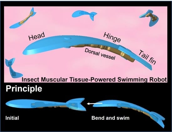
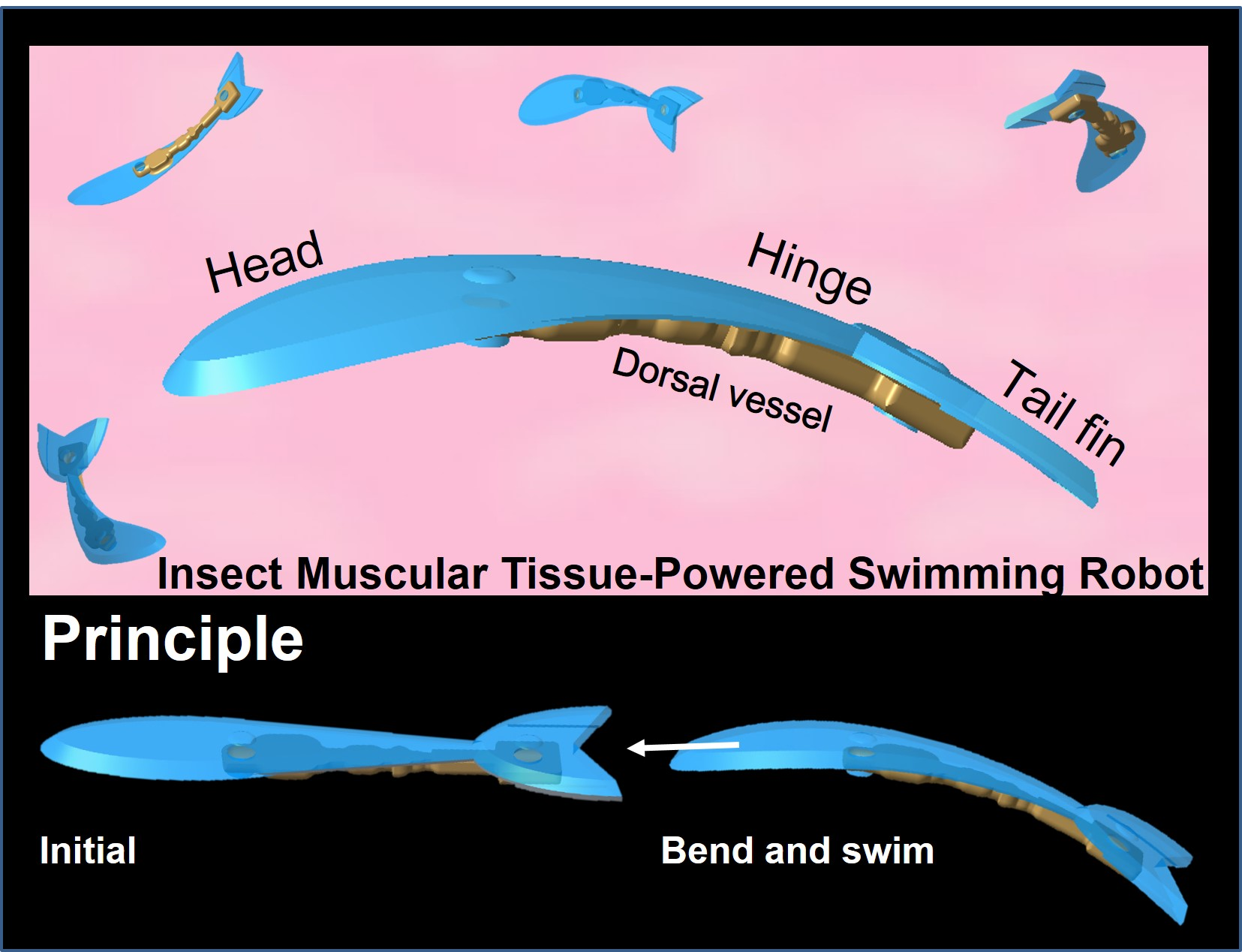
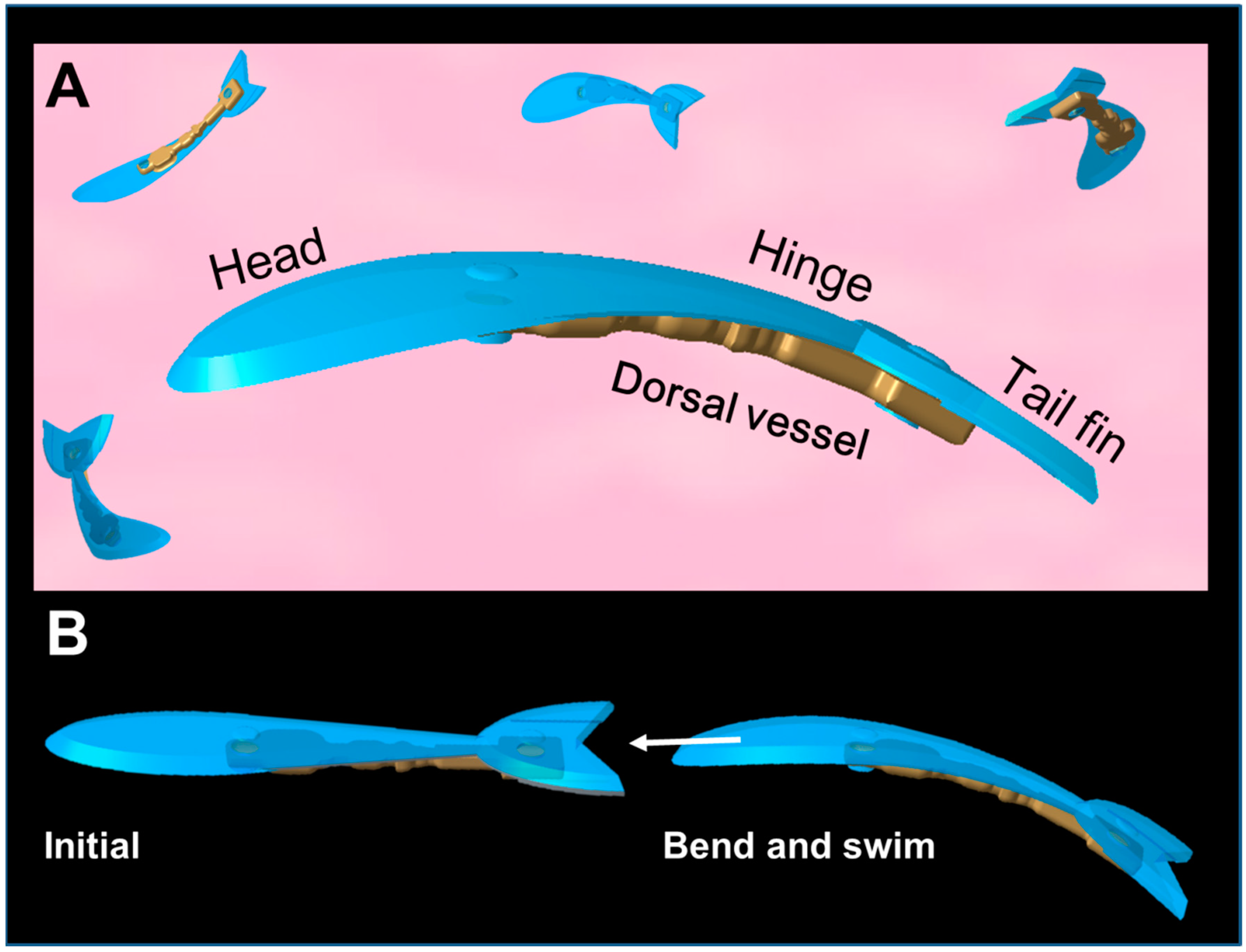
Insect Muscular Tissue-Powered Swimming Robot

1
Division of Materials Science, Nara Institute of Science and Technology, Ikoma 6300192, Japan
2
Laboratory for Integrated Biodevices, Center for Biosystems Dynamics Research, RIKEN, Suita 5650871, Japan
3
Department of Mechanical Engineering, Osaka University, Suita 5650871, Japan
4
Global Center for Medical Engineering and Informatics, Osaka University, Suita 5650871, Japan
5
Department of Mechanical Engineering and Robotics, Shinshu University, Ueda 3868567, Japan
6
Institute for Open and Transdisciplinary Research Initiatives, Osaka University, Suita 5650871, Japan
*
Authors to whom correspondence should be addressed.
Both authors contributed equally to this work.
Actuators 2019, 8(2), 30; https://doi.org/10.3390/act8020030
Submission received: 22 February 2019 / Revised: 2 April 2019 / Accepted: 4 April 2019 / Published: 8 April 2019

Abstract

:
Bio-actuators that use insect muscular tissue have attracted attention from researchers worldwide because of their small size, self-motive property, self-repairer ability, robustness, and the need for less environment management than mammalian cells. To demonstrate the potential of insect muscular tissue for use as bio-actuators, three types of these robots, a pillar actuator, a walker, and a twizzer, have been designed and fabricated. However, a model of an insect muscular tissue-powered swimming robot that is able to float and swim in a solution has not yet been reported. Therefore, in this paper, we present a prototype of an insect muscular tissue-powered autonomous micro swimming robot that operates at room temperature and requires no temperature and pH maintenance. To design a practical robot body that is capable of swimming by using the force of the insect dorsal vessel (DV), we first measured the contraction force of the DV. Then, the body of the swimming robot was designed, and the design was confirmed by a simulation that used the condition of measured contraction force. After that, we fabricated the robot body using polydimethylpolysiloxane (PDMS). The PDMS body was obtained from a mold that was fabricated by a stereo lithography method. Finally, we carefully attached the DV to the PDMS body to complete the assembly of the swimming robot. As a result, we confirmed the micro swimming robot swam autonomously at an average velocity of 11.7 μm/s using spontaneous contractions of the complete insect DV tissue. These results demonstrated that the insect DV has potential for use as a bio-actuator for floating and swimming in solution.

Graphical Abstract

1. Introduction

Bio-actuators are different from soft biomimetic actuators [1]; bio-actuators are a kind of actuator with an integrated biological organism and a micro structure made using polydimethylpolysiloxane (PDMS), polymer [2], and polylactic acid [3]. The principle of bio-actuators exploits their advantages of being self-actuated, wireless, and mechanochemical transducers that require no externally coupled energy source or stimuli, and a number of research studies on micro devices and cellular mechanical devices that use bio-actuators have been completed (see, for example, [4,5,6]). Two kinds of cells and tissues have mainly been used, mammalian and insect muscle cells and tissues, to demonstrate the potential of bio-actuators. Mammalian cells (such as cardiac and skeletal muscle cells) have received considerable attention, and bio-hybrid microdevices (the body structure can be made from polymer) were reported, including a pillar actuator and micro heart pumps [7,8,9,10,11], and different kinds of robots, including walking and swimming robots [12,13,14,15,16,17,18,19].
However, these mammalian muscle cells and tissue-integrated devices require precise environmental control to keep the contractile ability of the muscle cells. The culture medium must be replaced often, and the pH and temperature of the medium must be strictly controlled around 7.4 °C and 37 °C, respectively [20,21]. On the other hand, the tissues of insects are generally robust over a much wider range of living conditions compared with those of mammals. Baryshyan et al. [21] and Akiyama et al. [22] selected the insect tissue and the dorsal vessel (DV) as a bio-actuator. The DV is a central pulsating blood vessel located along the back of an insect, and it acts as a heart. This means that the DV autonomously contracts at a constant frequency without any kind of control or stimuli. The DV tissue was used to demonstrate a micro-pillar actuator [22,23], a walking robot [24], and an atmospheric-operable bio-actuator [20], which worked at room temperature for 90 days without medium replacement [23]. In these studies, this kind of actuator was also capable of working at temperatures from 5 to 40 °C, although the contracting velocity and frequency of the motion decreased with a lowering of temperature and the actuator was irreversibly damaged when the temperature was decreased below 5 °C. In addition, the chemical controllability of contractions using crustacean cardioactive peptide (CCAP) has been confirmed [25,26,27].
As the above studies about DV actuators demonstrate, the fundamental concept for fabricating insect cells and tissue-powered robots has been established. However, since all these previous bio-actuators were used in a liquid solution environment, the problems of weight, as the DV and robot body are large and heavy, and of the surface condition need to be addressed, which significantly limits the walking ability of conventional robots and even requires a specially fabricated surface to enhance moving velocity.
Swimming is a more effective method for moving in a solution than walking. Because the buoyancy force acting on the robot body in the solution is lightened relative to the force of gravity, the surface condition will not influence the motion of the robot, and the swimming robot has more degrees of freedom. Although a frog muscle tissue-actuated robot has been reported [16], it was larger and not autonomously actuated. All these reasons extend the possible applications of swimming robots by making it easier to carry more weight and extending the moving area. However, because the DV is heavier than the solution, a well-considered design of the robot body to keep the DV afloat in the solution and to allow for possible deformation when swimming is required.
Therefore, in this paper, we propose the concept of an insect muscular tissue-actuated autonomous swimming robot (Figure 1A). For this robot, we fixed the DV to the head and tail fin parts of the robot body and when the DV contracts, the tail fin of the robot bends significantly and pushes away the solution, which provides the pushing force and makes the robot move forward (Figure 1B).
Prior to fabricating the prototype swimming robot, in this research, we first measured the contraction force generated by the DV when we fixed it onto our self-made jig. Then, based on the measured results, we designed the prototype of the swimming robot of a several mm scale. The deformation of the robot was simulated and estimated using finite element analysis simulation software with an elastic model. Next, we verified the practicality of the robot body design by calculating the bending displacement; and we fabricated the body by a polydimethylpolysiloxane (PDMS) (SILPOT 184, Dow Corning Toray Co., Ltd., Tokyo, Japan) molding process. After that, the assembly of the swimming robot was completed by attaching the whole DV onto the body. Finally, the insect muscular tissue-powered swimming robot swam and was evaluated by measuring the moving distance from top and side video images.

2. Materials and Methods

2.1. Insect and its DV Preparation

As described in our previous reports [20,22,28,29], we used the final stage larvae of lepidopteran inchworms, Ctenoplusia agnate (Figure S1A). The inchworms were raised at room temperature (from 20–25 °C) on an artificial diet. Their DVs were excised manually under a stereomicroscope after undergoing surface sterilization in 70% ethanol solution to clean them. Then, these excised DVs were cultured in the culture medium (TC-100 insect culture medium, Sigma-Aldrich, Tokyo, Japan), supplemented with 10% fetal bovine serum and 1% penicillin-streptomycin. The preparation process requires the capability of distinguishing the DV tissue from other tissues (Figure S1B) that have a similar appearance.

2.2. Measurement of DV Contractile Force

The contractile force is the most import factor for the design of the swimming robot body. Therefore, we measured the contractile force of the DV tissue first. We previously developed the measuring method and measured several types of micro scale forces from other kinds of tissues, such as adhesion force [30,31] and tensile force [26,27]. The present measurement method results were used to evaluate the fundamental contractile properties of the DV tissue in the case of imposed length strain. The details of the measuring procedure were previously reported [29]. The contractile force autonomously generated by the DV was measured as a voltage signal through a force transducer by the micro force measurement and recording system (T009; Tech Alpha Co., Tokyo, Japan). These was no external control or stimuli applied on the DV. Stored data were analyzed with Excel. The temperature of the chamber in which the DV was placed on the self-made jig was kept at 25 °C based on temperature measurements using a thermocouple mounted in the force measurement system (Figure S2A).
For the measuring process, as shown in Figure S2B, we first fixed the two ends of the DV to the jig in the measurement system, then, the right side of the jig was fixed in place, and the left side was put in contact to the force transducer. When the DV contracted, the extra displacement generated a voltage signal that was recorded. At least 10 DV contraction cycles were recorded to measure the contractile force. The recorded data were analyzed with Excel. Furthermore, to maximize the muscular contractile force, the most appropriate extension was over 20% [32]; therefore, we verified different tension conditions of the DV to find the differences (Figure 2). When we applied a tension to extend the DV by more than 30% of its length, the DV was permanently damaged; therefore, we measured the contractile force of the DV in three tension conditions of the initial length, initial length + 10%, and initial length + 30%.

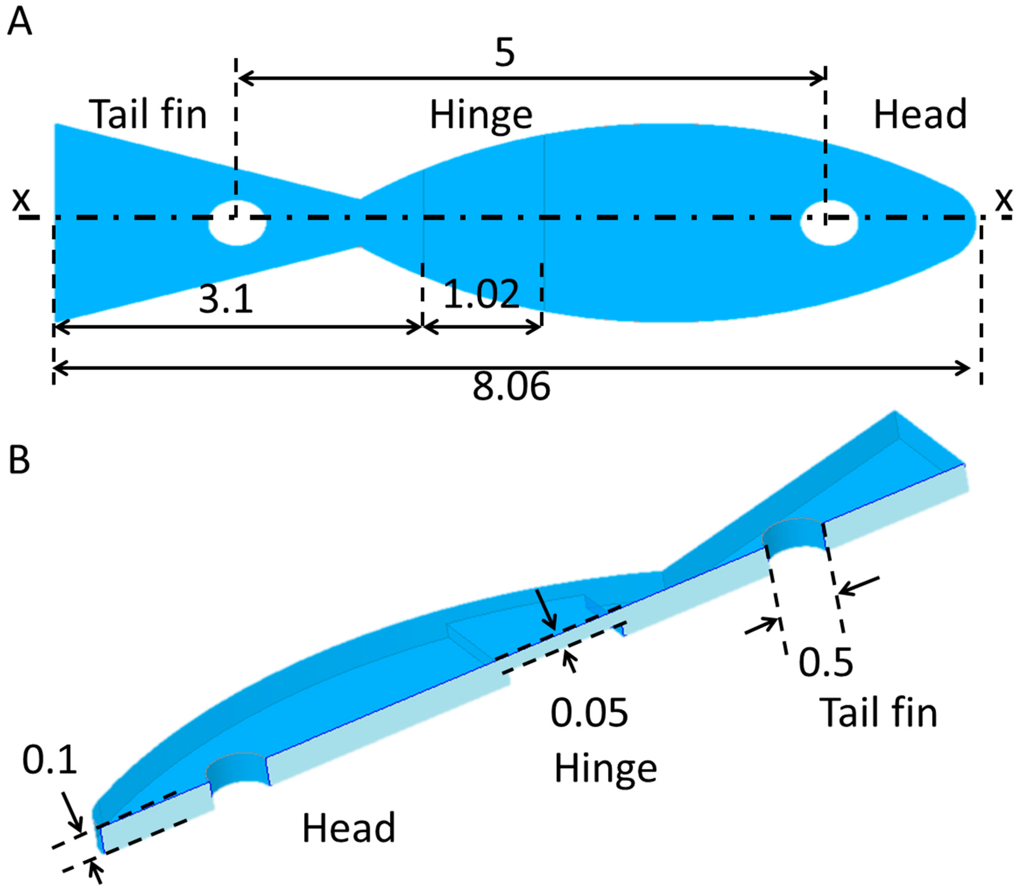
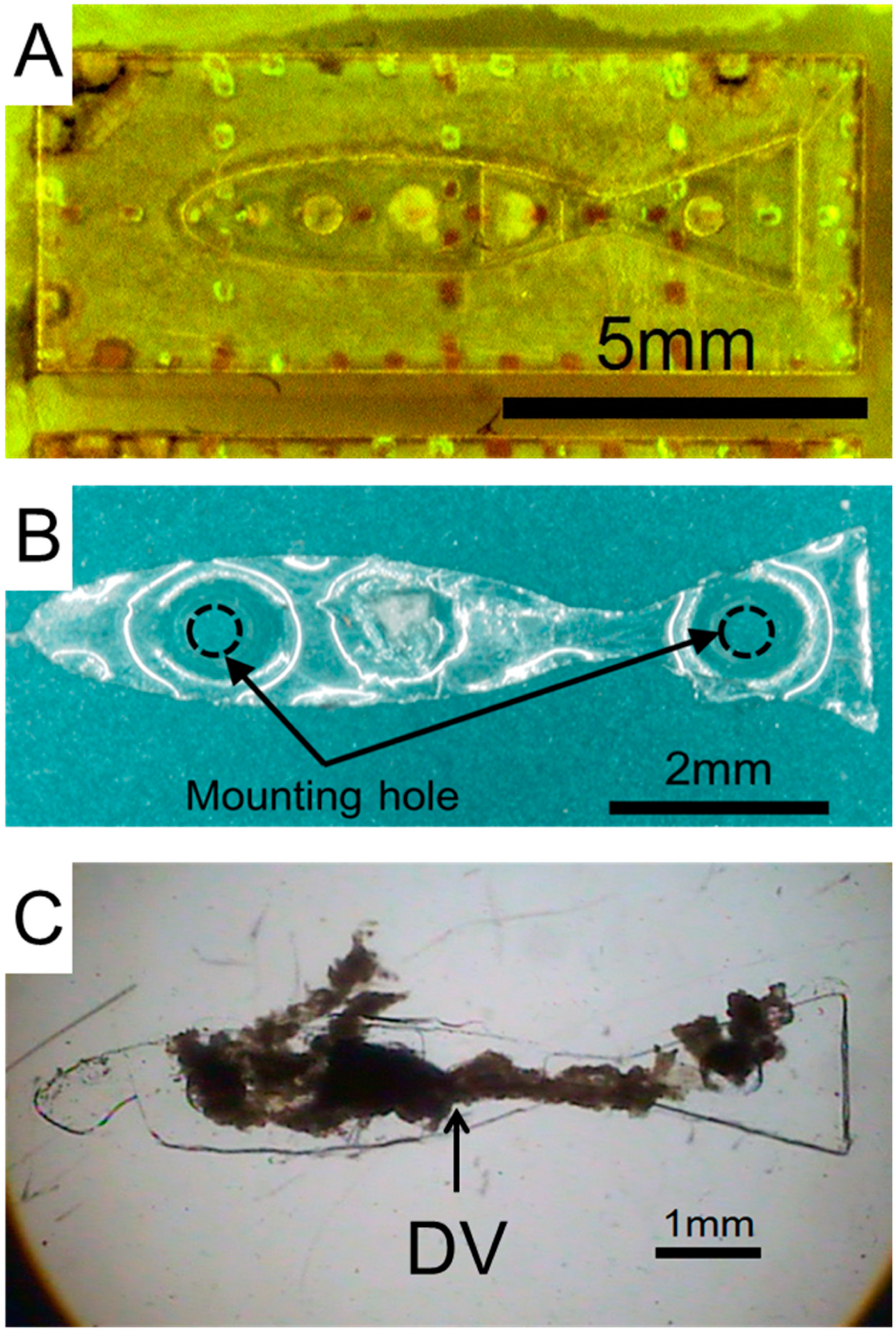
2.3. Design and Fabrication of the Prototype Swimming Robot

We designed the prototype swimming robot as shown in Figure 3. Based on the investigated value of the contractile force and the size of a complete DV tissue, we employed a fish body shape closely modeled after the actual anatomy of a mackerel. The design consisted of the head, hinge, and tail fin parts (Figure 3A). We thought that when the contractile force was applied on the tail fin, the tail fin would bend and push away a small amount of solution and achieve the driving force to swim forward.
The body was made of PDMS and its width and length were 8.06 × 2.3 mm (the ratio of the length axis to the short axis of this body size was 0.28, which is the value for a bluefin tuna body [33]). Two holes, each 500 μm in diameter, were made near each end of the body to hold the DV tissue in place when it was fixed to the body. To easily bend the body, the hinge thickness was 0.05 mm (Figure 3B), and the thickness of other body areas was 0.1 mm to allow manual handling. Then, to verify the principle of the design, we used a linear elastic deformation model (because the force of a bio-actuator is extremely small, the deformation is also small; therefore, instead of a complicated hyperelastic model, a simple elastic model was selected [34]) with the finite element simulation software, COMSOL Multiphysics (ver. 4.3a, COMSOL AB, Stockholm, Sweden), used to estimate possible deformation of the designed body (Figure 4). We first designed the body and input the body geometry into the software, then meshed the body using a pyramid type mesh. The simulation conditions are shown in Figure S3A,B. The head was fixed and held the body in place. Then, force was applied on the tail fin; specifically, a contractile force from 50 to 100 μN was loaded onto the edges of the tail fin where the DV tissue was fixed and the head of the body was constrained in the plane. Two things influence the displacement of the tail fin: The hinge thickness and Young’s modulus of the material. For easy handling, the thickness was set to 0.05 mm. The Young’s modulus of PDMS can be adjusted using the ratio of the curing agent (when the ratio is increased, Young’s modulus decreases) [35]. Normally, the ratio used is 10:1 and then Young’s modulus is around 2 MPa; we used that value of Young’s modulus for the simulation. Poisson’s ratio was 0.49 [32]. Simulation results for the deformation are shown in Figure 4A. The maximum displacement of the tail fin was about 1.3 mm (Figure 4B). This strongly suggested that the tail fin of the swimming robot would be able to bend significantly, and the motion would lead to forward movement by spontaneous contractions of the DV tissue. As a reference, we also investigated the relation between the displacement and hinge thickness and Young’s modulus when the applied force was 75 μN. The hinge thickness was from 0.03 to 0.10 mm, and Young’s modulus of PDMS was set from 0.4 to 2 MPa. These results are shown in Figure S3C,D. When the hinge thickness was increased, especially over 0.07 μm, the displacement of the tail fin decreased sharply. The displacements decreased with the increasing Young’s modulus.

2.4. Fabrication of Prototype Robot Body

The body for the swimming robot was fabricated in a molding PDMS process (Figure S4). The mold was fabricated by the stereolithography method. After the mold was fabricated (Figure 5A), uncured PDMS (Sylpod184, Dow Corning Toray, Tokyo, Japan) was poured into the mold. Next, a sliding glass was placed on the mold and they were pressed together in a vise in order to remove excess uncured PDMS. After baking at 80 °C for 90 min, the body and the slide glass were detached from the mold. Finally, the body was carefully peeled off without tearing and washed (Figure 5B).

2.5. Assembly of DV Tissue onto the Prototype Robot

For easy handling, the body of the robot was hydrophilized using an oxygen plasma asher (PIB-10, Vacuum Device, Ibaragi, Japan), and to prevent the DV from attaching to undesired areas of the robot body, most of the body was coated with Cell Tak (BD Biosciences, Franklin Lakes, NJ, USA). Then, while the body was immersed in the culture medium, the DV tissue was manually attached to the body using tweezers and while viewing the operation under the stereomicroscope. The body of the robot was then incubated at room temperature (20–25 °C) without medium replacement (Figure 5C).

2.6. Image Analysis for Evaluation of the Swimming Robot

The swimming robot was observed at room temperature in all the experiments. The deformation distance of the tail fin and moving distance of the swimming robot were respectively observed with a digital zoom microscope (KH-7700, Hirox, Tokyo, Japan) and a zoom microscope (AZ-100, Nikon, Tokyo, Japan) equipped with a Charge Coupled Device (CCD) camera. The obtained movies were analyzed with commercial analysis software (DippMotion, Ditect, Tokyo, Japan)

3. Results and Discussion

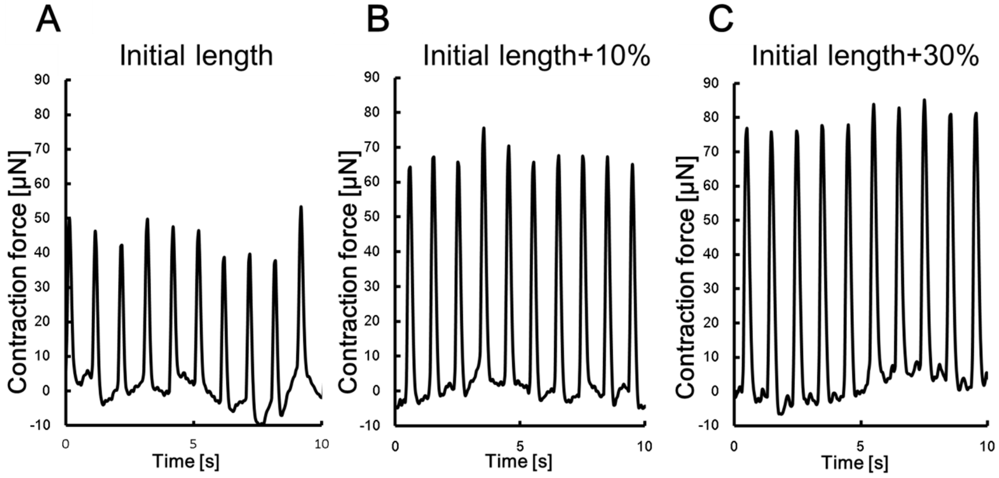
3.1. Measurement of DV Contractile Force

The results of the DV contractile force are shown in Figure 2A–C. In these conditions of the initial DV length, initial length + 10%, and initial length + 30%, the average contractile forces were approximately 42.7, 66.8, and 79.6 μN, respectively. In previous research [29], the force was confirmed to range from 7 to 100 μN and the present average values are in that range. The tension condition significantly affected the force performance, and the contractile force measured from the initial length + 30% condition of the DV was selected to design the body of the robot. Table 1 summarizes the performance of the bio-actuators that were described in other studies and this study. Uesugi et al. [29] measured the contractile forces of DV tissues loaded with 20% strain. The measured contractile forces were from 10.5 µN to 87.3 µN. The values were similar to our study findings. Palmer et al. [36] measured the contractile force of cardiomyocytes and obtained a value of 22.3 kPa, while Lin et al. [37] also measured them and obtained a value of 23.7 kPa. These contractile forces were larger than our study findings. The low contractile performance of our study could be due to two reasons. The first reason was the damage of the DV tissues by the manual operations of dissection and handling for fabrication of the micro robot. The second reason was shrinking of the DV tissues. When excising the DV tissue from larvae, the DV tissues shrank extensively and the contractile force could also correspondingly decrease. On the other hand, the contractile force of engineered heart tissues (EHTs) was nearly the same order as in our study (3 kPa, obtained by Zimmermann et al. [38]). However, those heart tissues required careful maintenance of the environment.
In addition, although the average contractile forces were from 42.7 to 79.6 μN, which seems small, with proper strategies (consider the use of light material and driving algorithm) of body material selection, structure design, and control [2,39,40], the bio-actuator can be used to handle small delicate objects.

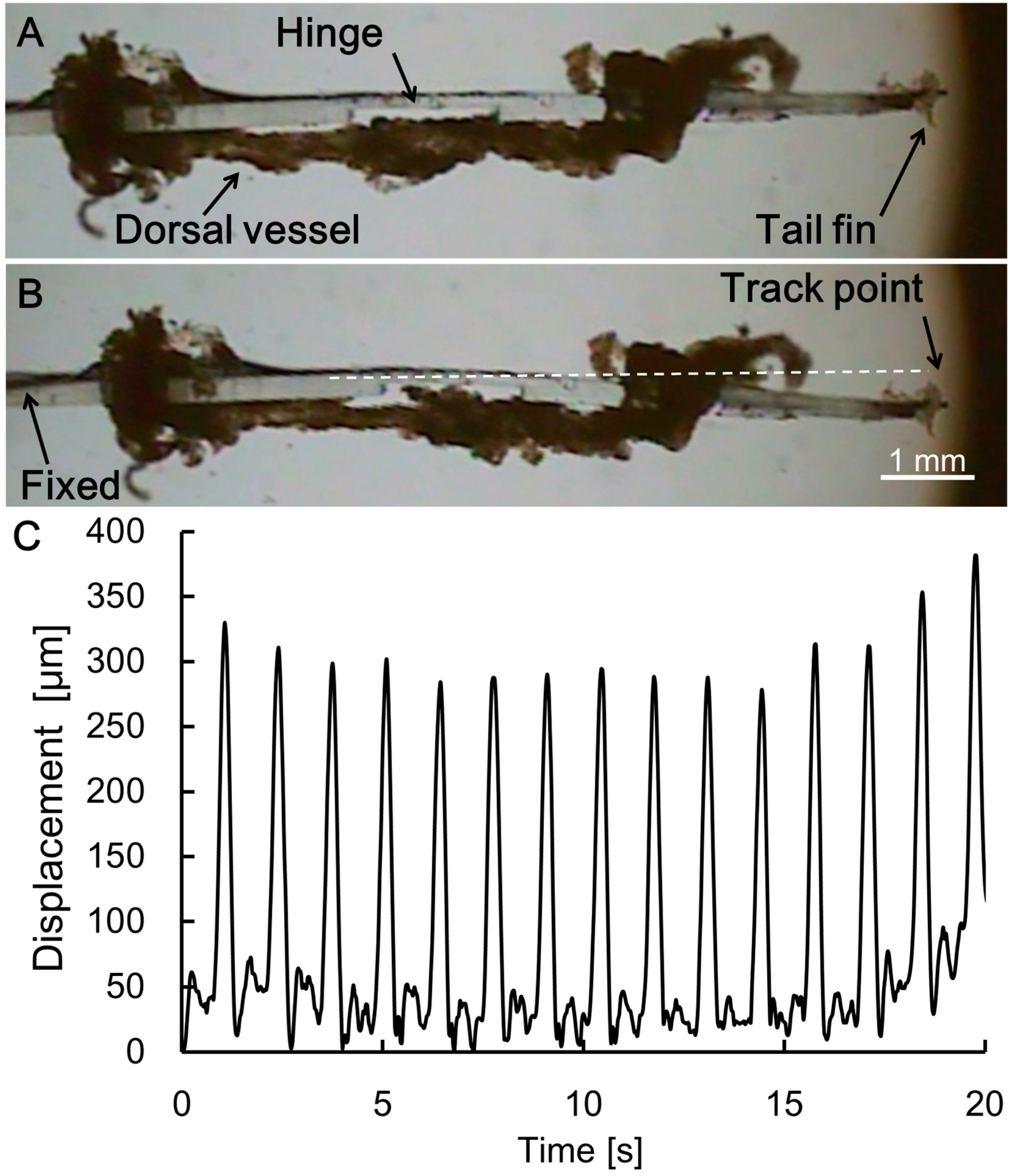
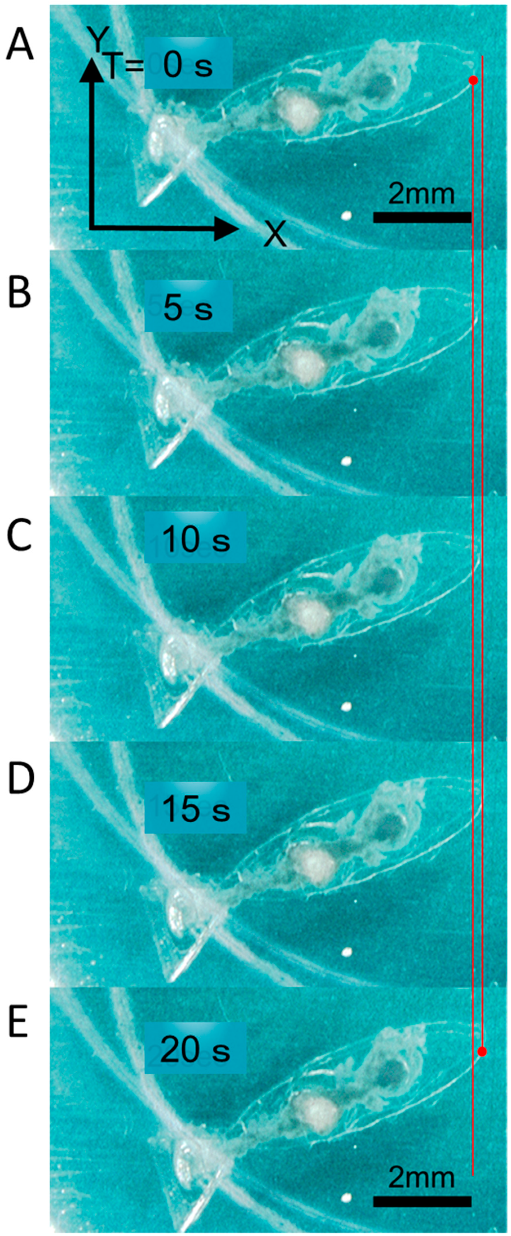
3.2. Motion Analysis of the Swimming Robot Tail Fin

The deformation of the tail fin motion of the prototype swimming robot was measured from the top (Figure 6 and Video S1). Views of the relaxing and contracting swimming robot are shown in Figure 6A,B. The DV tissue under the body contracted spontaneously, and that action bent the body. The change in the distance between the relaxed and contracted conditions was measured as 257.41 μm to 387.51 μm. The motion was stable and continuous (Figure 6C). The measured value was significantly less than the predicted value in the simulation, which was 0.65 to 1.04 mm. We attributed the difference to three possible causes: The actual stiffness of the PDMS, which depends on the baking time and temperature, differed from the stiffness assumed in the simulation; there was variability of the contractile force among individual DV tissues; and the DV tissue was damaged during assembly. Even so, when we compared our displacement with other displacements obtained previously, approximately 30 μm (PDMS pillar) [28], 25 μm (PDMS pillar) [22], and 120 μm (actuator in air) [20], our displacement was larger.

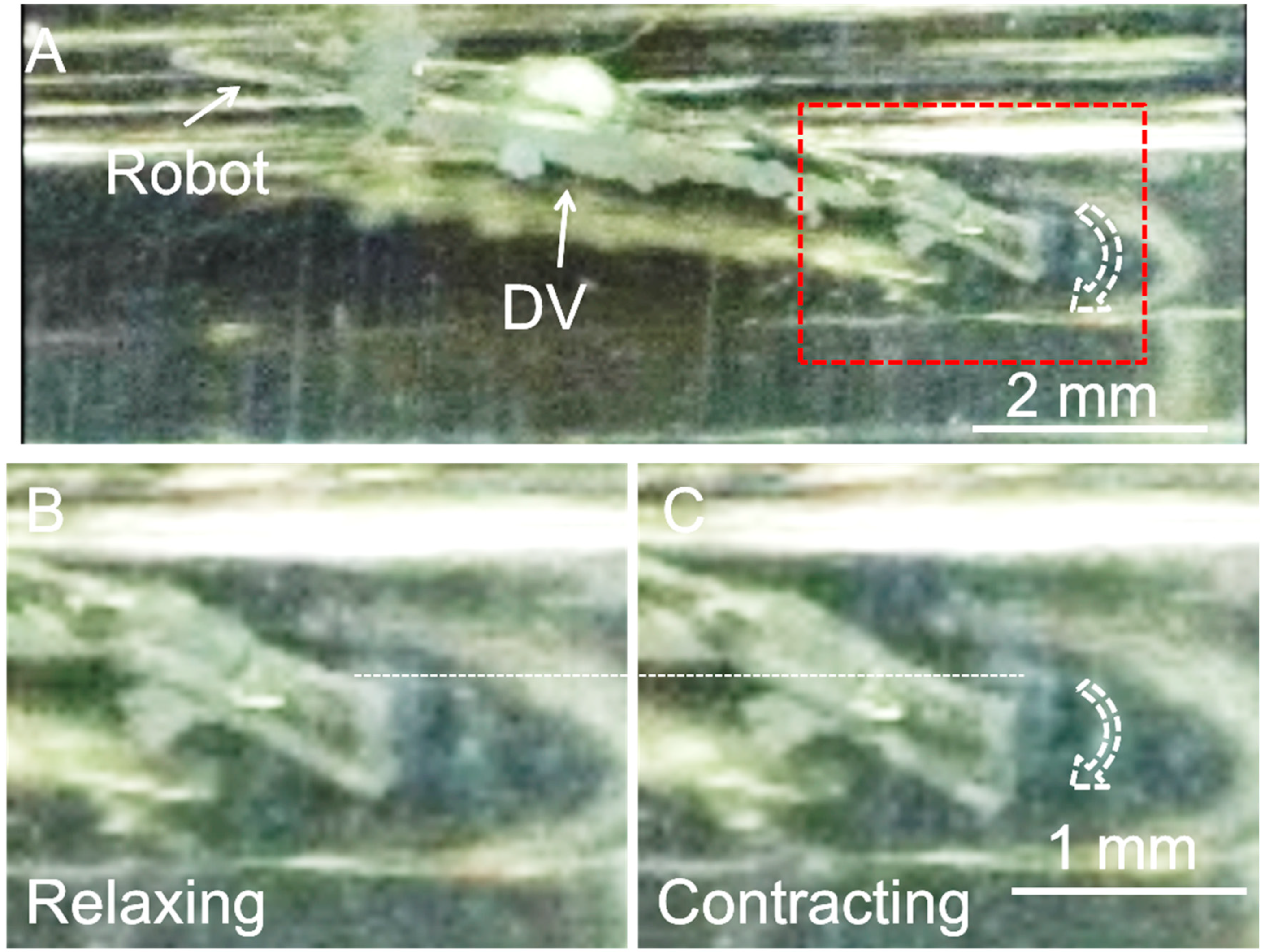
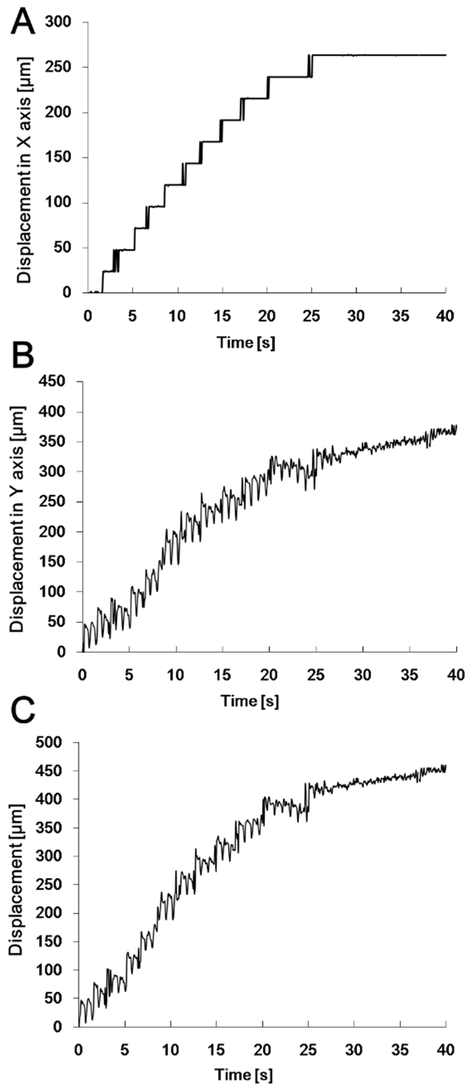
3.3. Motion Analysis of the Swimming Robot

After the confirmation of tail fin motion for the fixed body, the robot was released into a liquid solution to observe its actual swimming capability. Just as in the motions captured in Figure 6 and Figure 7, and Video S2, the robot shook its tail fin and swam. During 30 s, the robot swam a distance of 457 μm while the DV tissue contracted 11 times (Figure 8 and Figure 9, and Video S3). Based on these results, we calculated the average stroke and forward velocity as 44.7 μm and 11.7 μm/s. The direction of swimming was not exclusively in the forward direction; the displacement on the X-axis (Figure 9A) was 2/3 of that on the Y-axis (Figure 9B), and the swimming velocity on the X-axis (Figure 9A) was approximately 10 μm/s, which was 2/3 of that on the Y-axis (Figure 9B), which lead to a side motion (Figure 9C). These results showed the contractile force of the DV was utilized poorly and the swimming robot needed a balance adjustment after the DV tissue was assembled. The efficiency of swimming could be improved by using a balancer or reconsidering the design of the robot body by adding more hinges or a wing for horizontal balance. If the contractile force of the DV is evoked efficiently by improving the shape of the body shape to cancel the side motion, theoretically, the forward velocity of the swimming robot will increase to 44.7 μm/s (single average stroke).
Although the swimming speed of our insect muscular tissue-powered robot was significantly slower than that of some other swimming robots as shown in Table 2 [6], when we compared the potential properties of long-term driving and robustness, our insect tissue-powered robot had obvious advantages. First, it is relatively easy to achieve mm-order muscle tissue without careful control of the environment. Secondly, our robot is cost-effective as a research model for bio-actuators without conducting animal (vertebrata) experiments. According to our previous work [23], the DV tissues works at 0.15 Hz on average for 90 days. The whole contraction time during its life time can be roughly estimated at 1.17 × 10⁶ times. The DV tissues that were extended and fixed on the robot body might have an influence on the life time.

4. Conclusions

In this paper, for the first time, we designed and presented a prototype insect tissue-powered autonomous swimming robot that functioned at room temperature without temperature and pH maintenance. We first measured the contraction force of different tension conditions of the DV as 42.7 to 79.6 μN. Next, the swimming robot body was designed and simulated using the above measured force, and the estimated deformation of the body was 1.3 mm. Then, we fabricated the body using PDMS. Finally, we carefully attached a DV tissue to the PDMS body to complete the assembly of the swimming robot. Although the swimming speed (11.7 μm/s (actual), 44.7 μm/s (theoretical)) was slower than that of other types of swimming robots, by improving the shape of the body, such as through a lighter and smaller design or by accelerating the movement by adding a chemical reagent, we expect it will be possible to increase the swimming speed significantly. This research is important for two reasons. First, we proved that insect DV tissue has high potential to be used as a bio-actuator element for swimming robots. Second, we offered a fundamental, cost-effective, near-to-life, easy-to-maintain, bio-actuator solution to help researchers explore the research field of bio-actuators, without animal (vertebrata) experiments.

Supplementary Materials

The following are available online at https://www.mdpi.com/2076-0825/8/2/30/s1, Figure S1: Insect tissue material, Figure S2: Micro force measurement and recording system, Figure S3: Details of the simulation, Figure S4: Fabrication process for the robot body, Video S1: The deformation of the tail fin motion of the prototype swimming robot was measured from this video, Video S2: The motions showing that the robot shook its tail fin and swam, Video S3: During 30 s, the robot swam a distance of 457 μm while the DV tissue contracted 11 times, Video S4: 10 times faster movie of S3.

Author Contributions

Data curation, Y.Y., K.U. and M.H.; Formal analysis, Y.A.; Funding acquisition, Y.Y.; Investigation, K.U.; Methodology, Y.Y.; Project administration, K.M.; Supervision, K.M.; Validation, Y.S. and Y.T.; Writing—original draft, Y.Y.

Funding

The present work was supported by JSPS, MEXT KAKENHI Grant Numbers 20034017, 21676002, 21225007, 21111503, 22860020, 23111705, and 23700557, 26249027, 17H01254.

Conflicts of Interest

The authors declare no conflict of interest.

References

  1. Umedachi, T.; Vikas, V.; Trimmer, B.A. Softworms: The design and control of non-pneumatic, 3D-printed, deformable robots. Bioinspir. Biomim. 2016, 11, 025001. [Google Scholar] [CrossRef]
  2. Slesarenko, V.; Engelkemier, S. Strategies to Control Performance of 3D-Printed, Cable-Driven Soft Polymer Actuators: From Simple Architectures to Gripper Prototype. Polymers 2018, 10, 846. [Google Scholar] [CrossRef] [PubMed]
  3. Yalikun, Y.; Noguchi, Y.; Kamamichi, N.; Tanaka, Y. Atmospheric-Operable 3D Printed Walking Bio-Robot Powered by Muscle-Tissue of Earthworm. In Proceedings of the 2018 IEEE/RSJ International Conference on Intelligent Robots and Systems (IROS), Madrid, Spain, 1–5 October 2018; pp. 7595–7600. [Google Scholar]
  4. Stanton, M.M.; Trichet-Paredes, C.; Sanchez, S. Applications of three-dimensional (3D) printing for microswimmers and bio-hybrid robotics. Lab Chip 2015, 15, 1634–1637. [Google Scholar] [CrossRef]
  5. Chan, V.; Asada, H.H.; Bashir, R. Utilization and control of bioactuators across multiple length scales. Lab Chip 2014, 14, 653–670. [Google Scholar] [CrossRef] [PubMed]
  6. Feinberg, A.W. Biological Soft Robotics. Annu. Rev. Biomed. Eng. 2015, 17, 243–265. [Google Scholar] [CrossRef]
  7. Morishima, K.; Tanaka, Y.; Ebara, M.; Shimizu, T.; Kikuchi, A.; Yamato, M.; Okano, T.; Kitamori, T. Demonstration of a bio-microactuator powered by cultured cardiomyocytes coupled to hydrogel micropillars. Sens. Actuators B Chem. 2006, 119, 345–350. [Google Scholar] [CrossRef]
  8. Tanaka, Y.; Morishima, K.; Shimizu, T.; Kikuchi, A.; Yamato, M.; Okano, T.; Kitamori, T. An actuated pump on-chip powered by cultured cardiomyocytes. Lab Chip 2006, 6, 362–368. [Google Scholar]
  9. Tanaka, Y.; Sato, K.; Shimizu, T.; Yamato, M.; Okano, T.; Kitamori, T. A micro-spherical heart pump powered by cultured cardiomyocytes. Lab Chip 2007, 7, 207–212. [Google Scholar] [CrossRef]
  10. Park, J.; Kim, I.C.; Baek, J.; Cha, M.; Kim, J.; Park, S.; Lee, J.; Kim, B. Micro pumping with cardiomyocyte-polymer hybrid. Lab Chip 2007, 7, 1367–1370. [Google Scholar] [CrossRef]
  11. Tanaka, Y.; Fujita, H. Fluid driving system for a micropump by differentiating iPS cells into cardiomyocytes on a tent-like structure. Sens. Actuators B Chem. 2015, 210, 267–272. [Google Scholar] [CrossRef]
  12. Kim, J.; Park, J.; Yang, S.; Baek, J.; Kim, B.; Lee, S.H.; Yoon, E.-S.; Chun, K.; Park, S. Establishment of a fabrication method for a long-term actuated hybrid cell robot. Lab Chip 2007, 7, 1504–1508. [Google Scholar] [CrossRef]
  13. Williams, B.J.; Anand, S.V.; Rajagopalan, J.; Saif, M.T. A self-propelled biohybrid swimmer at low Reynolds number. Nat. Commun. 2014, 5, 3081. [Google Scholar] [CrossRef] [PubMed]
  14. Feinberg, A.W.; Feigel, A.; Shevkoplyas, S.S.; Sheehy, S.; Whitesides, G.M.; Parker, K.K. Muscular thin films for building actuators and powering devices. Science 2007, 317, 1366–1370. [Google Scholar] [CrossRef] [PubMed]
  15. Nawroth, J.C.; Lee, H.; Feinberg, A.W.; Ripplinger, C.M.; Mccain, M.L.; Grosberg, A.; Dabiri, J.O.; Parker, K.K. A tissue-engineered jellyfish with biomimetic propulsion. Nat. Biotechnol. 2012, 30, 792–797. [Google Scholar] [CrossRef]
  16. Herr, H.; Dennis, R.G. A swimming robot actuated by living muscle tissue. J. Neuroeng. Rehabil. 2004, 1, 6. [Google Scholar] [CrossRef] [PubMed]
  17. Chan, V.; Park, K.; Collens, M.B.; Kong, H.; Saif, T.A.; Bashir, R. Development of miniaturized walking biological machines. Sci. Rep. 2012, 2, 857. [Google Scholar] [CrossRef] [PubMed]
  18. Park, S.-J.; Gazzola, M.; Park, K.S.; Park, S.; Di Santo, V.; Blevins, E.L.; Lind, J.U.; Campbell, P.H.; Dauth, S.; Capulli, A.K.; et al. Phototactic guidance of a tissue-engineered soft-robotic ray. Science 2016, 353, 158–162. [Google Scholar] [CrossRef] [PubMed]
  19. Xi, J.; Schmidt, J.J.; Montemagno, C.D. Self-assembled microdevices driven by muscle. Nat. Mater. 2005, 4, 180–184. [Google Scholar] [CrossRef]
  20. Akiyama, Y.; Sakuma, T.; Funakoshi, K.; Hoshino, T.; Iwabuchi, K.; Morishima, K. Atmospheric-operable bioactuator powered by insect muscle packaged with medium. Lab Chip 2013, 13, 4870–4880. [Google Scholar] [CrossRef]
  21. Baryshyan, A.L.; Domigan, L.J.; Hunt, B.; Trimmer, B.A.; Kaplan, D.L. Self-assembled insect muscle bioactuators with long term function under a range of environmental conditions. RSC Adv. 2014, 4, 39962. [Google Scholar] [CrossRef]
  22. Akiyama, Y.; Odaira, K.; Iwabuchi, K.; Morishima, K. Long-term and room temperature operable bio-microrobot powered by insect heart tissue. In Proceedings of the IEEE International Conference on Micro Electro Mechanical Systems (MEMS), Cancun, Mexico, 23–27 January 2011; pp. 145–148. [Google Scholar]
  23. Akiyama, Y.; Odaira, K.; Iwabuchi, K.; Morishima, K. Long-term and room temperature operable bioactuator powered by insect dorsal vessel tissue. Lab Chip 2009, 9, 140–144. [Google Scholar] [CrossRef] [PubMed]
  24. Akiyama, Y.; Odaira, K.; Sakiyama, K.; Hoshino, T.; Iwabuchi, K.; Morishima, K. Rapidly-moving insect muscle-powered microrobot and its chemical acceleration. Biomed. Microdevices 2012, 14, 979–986. [Google Scholar] [CrossRef] [PubMed]
  25. Akiyama, Y.; Iwabuchi, K.; Furukawa, Y.; Morishima, K. Biological contractile regulation of micropillar actuator driven by insect dorsal vessel tissue. In Proceedings of the 2008 2nd IEEE RAS & EMBS International Conference on Biomedical Robotics and Biomechatronics, Scottsdale, AZ, USA, 19–22 October 2008; pp. 501–505. [Google Scholar]
  26. Uesugi, K.; Akiyama, Y.; Hoshino, T.; Akiyama, Y.; Yamato, M.; Okano, T.; Morishima, K. Measuring mechanical properties of cell sheets by a tensile test using a self-attachable fixture. J. Robot. Mechatron. 2013, 25, 603–610. [Google Scholar] [CrossRef]
  27. Uesugi, K.; Akiyama, Y.; Hoshino, T.; Akiyama, Y.; Yamato, M.; Okano, T.; Morishima, K. Measurement system for biomechanical properties of cell sheet. In Proceedings of the 2013 IEEE/RSJ International Conference on Intelligent Robots and Systems, Tokyo, Japan, 3–7 November 2013; pp. 1010–1015. [Google Scholar]
  28. Akiyama, Y.; Iwabuchi, K.; Furukawa, Y.; Morishima, K. Fabrication and evaluation of temperature-tolerant bioactuator driven by insect heart cells. In Proceedings of the Twelfth International Conference on Miniaturized Systems for Chemistry and Life Sciences, San Diego, CA, USA, 12–16 October 2008; pp. 1669–1671. [Google Scholar]
  29. Uesugi, K.; Shimizu, K.; Akiyama, Y.; Hoshino, T.; Iwabuchi, K.; Morishima, K. Contractile Performance and Controllability of Insect Muscle-Powered Bioactuator with Different Stimulation Strategies for Soft Robotics. Soft Robot. 2016, 3, 13–22. [Google Scholar] [CrossRef]
  30. Uesugi, K.; Akiyama, Y.; Yamato, M.; Okano, T.; Hoshino, T.; Morishima, K. Development of cell-sheet handling tool for measurement of cell sheet adhesion force. In Proceedings of the 2009 International Symposium on Micro-NanoMechatronics and Human Science, Nagoya, Japan, 9–11 November 2009; pp. 614–619. [Google Scholar]
  31. Uesugi, K.; Akiyama, Y.; Hoshino, T.; Akiyama, Y.; Yamato, M.; Okano, T.; Morishima, K. Measuring adhesion force of a cell sheet by the ninety-degree peel test using a multi hook type fixture. J. Biomech. Sci. Eng. 2013, 8, 129–138. [Google Scholar] [CrossRef]
  32. Gordon, A.M.; Huxley, A.F.; Julian, F.J. The variation in isometric tension with sarcomere length in vertebrate muscle fibres. J. Physiol. 1966, 184, 170–192. [Google Scholar] [CrossRef]
  33. Videler, J.J. Fish Swimming; Springer: Dordrecht, The Netherlands, 1993; Volume 10, ISBN 9780470015902. [Google Scholar]
  34. Houaria, B.; Chellali, B. Study of the mechanical behavior of a hyperelastic membrane. Sens. Transducers 2014, 168, 108–112. [Google Scholar]
  35. Wang, Z.; Volinsky, A.A.; Gallant, N.D. Crosslinking Effect on Polydimethylsiloxane Elastic Modulus Measured by Custom-Built Compression Instrument. J. Appl. Polym. Sci. 2014, 131, 41050. [Google Scholar] [CrossRef]
  36. Palmer, R.O.Y.E.; Brady, J.; Roos, P.; Roy, E.; Brady, A.J. Mechanical measurements using a pipette attachment from isolated system cardiac myocytes. Am. J. Physiol. Cell Physiol. 1996, 270, C697–C704. [Google Scholar] [CrossRef]
  37. Lin, G.; Pister, K.S.J.; Roos, K.P. Surface micromachined polysilicon heart cell force transducer. J. Microelectromechan. Syst. 2000, 9, 9–17. [Google Scholar] [CrossRef]
  38. Zimmermann, W.H.; Melnychenko, I.; Eschenhagen, T. Engineered heart tissue for regeneration of diseased hearts. Biomaterials 2004, 25, 1639–1647. [Google Scholar] [CrossRef]
  39. Xu, Q. Design and Implementation of Large-Range Compliant Micropositioning Systems; Wiley: Hoboken, NJ, USA, 2016; ISBN 9781119131434. [Google Scholar]
  40. Vijayasai, A.P.; Sivakumar, G.; Mulsow, M.; Lacouture, S.; Holness, A.; Dallas, T.E. Haptic controlled three-axis MEMS gripper system. Rev. Sci. Instrum. 2010, 81, 105114. [Google Scholar] [CrossRef] [PubMed]
Figure 1. (A) Schematic views of an insect muscular tissue-powered swimming robot. The body of the swimming robot can be separated into the head, hinge, and tail fin parts. (B) The two ends of the DV are fixed to the head and tail fin of the robot body, and when the DV contracts, the robot bends and pulls away from the solution, thereby moving forward.
Actuators 08 00030 g001
Figure 2. Results obtained by the contractile force measurement method for three tension conditions: (A) Initial length, (B) initial length + 10%, and (C) initial length + 30%. The respective average contractile forces were approximately 42.7, 66.8, and 79.6 μN.
Actuators 08 00030 g002
Figure 3. Schematic drawings showing the dimensions (unit: mm) of the prototype swimming robot. (A) Top view of the robot body. (B) Cross-sectional view on the X-X line in (A).
Actuators 08 00030 g003
Figure 4. Simulation results obtained for the designed swimming robot body. (A) Deformation results are shown for the DV contraction forces of 50, 60, 70, 80, 90, and 100 μN. (B) Simulation results show the displacement of tail fin increased with the contraction force.
Actuators 08 00030 g004
Figure 5. Photos of the products. (A) The mold fabricated by the stereolithography method. (B) The PDMS body of the robot after the baking process was carried out at 80 °C for 90 min. (C) The swimming robot with the attached DV.
Actuators 08 00030 g005
Figure 6. Motion analysis of the swimming robot tail fin. (A) Image of the swimming robot tail fin in a relaxed condition. The head of the robot was fixed and the motion of the track point was analyzed. (B) Image of the swimming robot tail fin in a contracting condition. The tail fin was slightly bent. The white scale bar is 1 mm. (C) Displacement of the tail fin of the swimming robot was plotted from the image analysis.
Actuators 08 00030 g006
Figure 7. Motion of the swimming robot when it was released into a solution environment. (A) Image taken from the side direction of a video recording showing a bending motion of the tail fin. (B) Image of the swimming robot in a relaxed condition. (C) Image of the swimming robot in a contracted condition.
Actuators 08 00030 g007
Figure 8. Images showing the swimming of the insect muscle powered robot. (AE) The images were captured from the video recording of S2 at 5 s intervals, and the robot swam for a distance of about 400 μm at a velocity of 11.7 μm/min. The left and right vertical red lines indicate the initial and final positions in the video, respectively.
Actuators 08 00030 g008
Figure 9. The motion analysis results obtained for the swimming robot. The direction of swimming was separated into X-axis and Y-axis motions. (A) Displacement of the swimming robot on the X-axis. (B) Displacement of the swimming robot on the Y-axis. (C) Total displacement of the swimming robot.
Actuators 08 00030 g009
Table 1. Contractile performance of each type of biological actuator.
Biological ComponentDiameterPerformanceReference
ForceNormalizing
Insect dorsal vessel tissue217 µm42.7 µN (10% strain)
66.8 µN (20% strain)
79.6 µN (30% strain)
1.15 kPa (10% strain)
1.81 kPa (20% strain)
2.15 kPa (30% strain)
This study
Insect dorsal vessel tissue~500 µm10.5 to 87.3 µN (20 % strain)-[29]
Cardiomyocyte20 to 30 µm11.5 µN22.3 kPa[36]
Cardiomyocyte~30 µm12.6 µN23.7 kPa[37]
Engineered heart tissue
(Cardiomyocyte+ ECMs gel)
~1 mm-3 kPa[38]
Table 2. Comparison between other tissue type-swimming robots and our insect muscular tissue-powered robot.
Size (mm)MaterialEnvironment MaintenanceSpeed (µm/s)Tissue TypeReference
2PDMSNecessary5–10Cardiomyocyte cluster[13]
2PDMSNecessary81Cardiomyocyte cluster[13]
6PDMSNecessary400Cardiac cell tissue[14]
8PDMSNecessary1500Cardiac cell tissue[15]
8.02PDMSUnnecessary within 90 days [23] 11.7/44.7 (theoretical) Insect tissueThis study
120PDMSNecessary45,000Frog muscle tissue[16]

