Simultaneous Enhancement of Bending and Blocking Force of an Ionic Polymer-Metal Composite (IPMC) by the Active Use of Its Material Characteristics Change
Abstract
1. Introduction
2. Specimen Preparation
2.1. Materials
2.2. IPMCs with the Thin Silver Coating
2.3. IPMCs with the Thick Silver Coating
2.4. Storage of IPMCs
3. Prior Knowledge of the Dehydrated IPMC
4. Measurement
4.1. Bending Test
4.2. Force Generation
4.3. Evaluation of the IPMC Bending Stiffness
4.4. Scrutinizing the Silver Layer Condition
5. Results and Discussion
5.1. Nafion-Based IPMC
5.1.1. Bending, Blocking Force and Bending Stiffness under the Constant Voltage
5.1.2. Bending and Blocking Force under the Constant Current
5.1.3. Characteristics of the Silver Layer
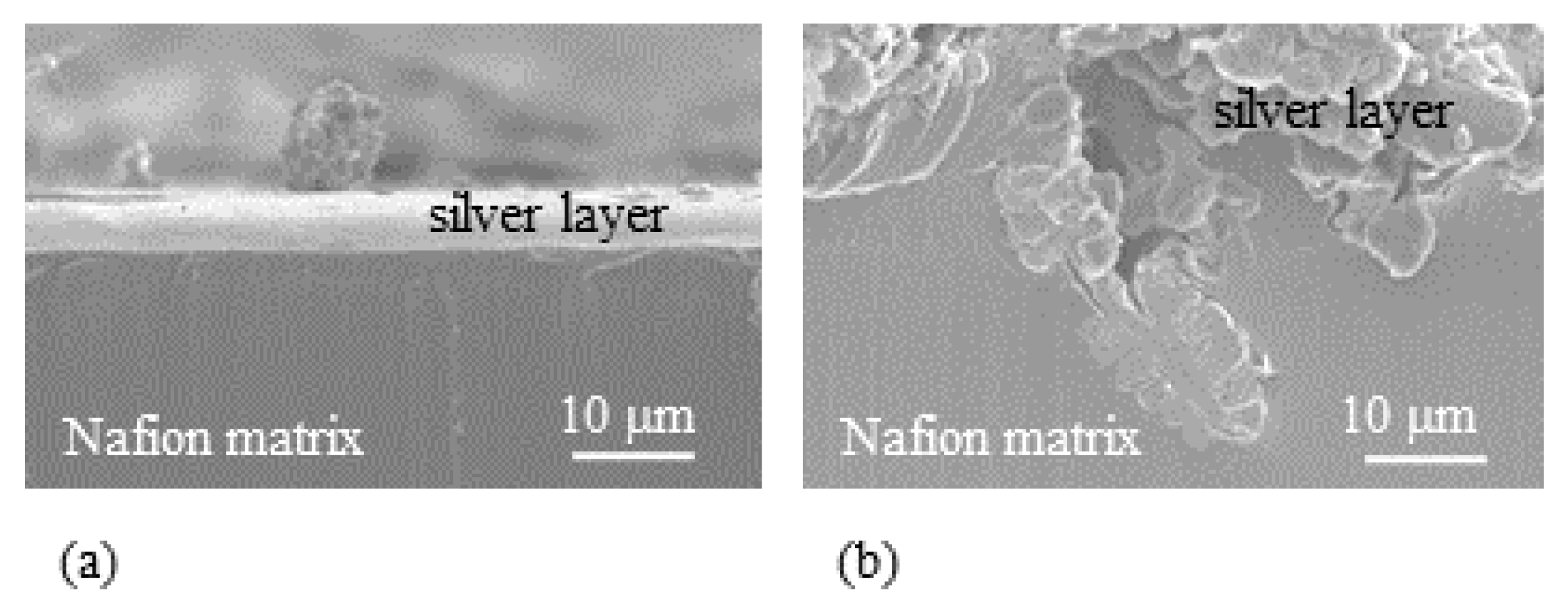
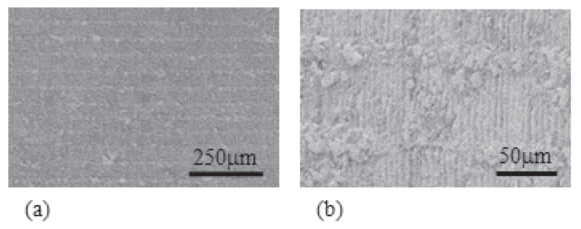
- Experiment (i) Since the averaged thickness of L-Naf is 208 m and that of S-Naf is 188 m as summarized in Table 1, the silver coating of L-Naf is 10 m thicker than that of S-Naf based on the simple calculation (208 m − 188 m) ÷ 2 = 10 m. However, the SEM images in Figure 10 show that the silver layer of L-Naf penetrates a bit far inside of Nafion body, the penetration depth of silver is not included in that 10 m, while the silver layer of S-Naf is formed merely on the Nafion surface.In addition to the SEM images shown in Figure 10, we obtained the following outcomes concerning the above-described experiments, (ii), (iii) and (iv).
- Experiment (ii) We found that the mass ratio of silver to oxygen in the oxidized silver coating of L-Naf was 6:1, while that of the reduced silver coating was 20:1. This EDX result suggests that the voltage impose and its polarity change causes the characteristic change of L-Naf, and it is true for S-Naf, too.
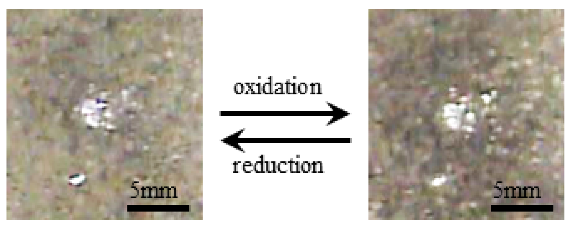
- Experiment (iii) Upon the voltage imposed on S-Naf and L-Naf, the color of their anode surface changed from bright white to a slight dark brown due to the oxidation of silver into silver dioxide. The polarity change of voltage resulted in the change of dark brown surface back into to the initial bright white surface due to the reduction of silver dioxide into silver. Figure 11 shows the typical surface color change of L-Naf by the redox reaction.
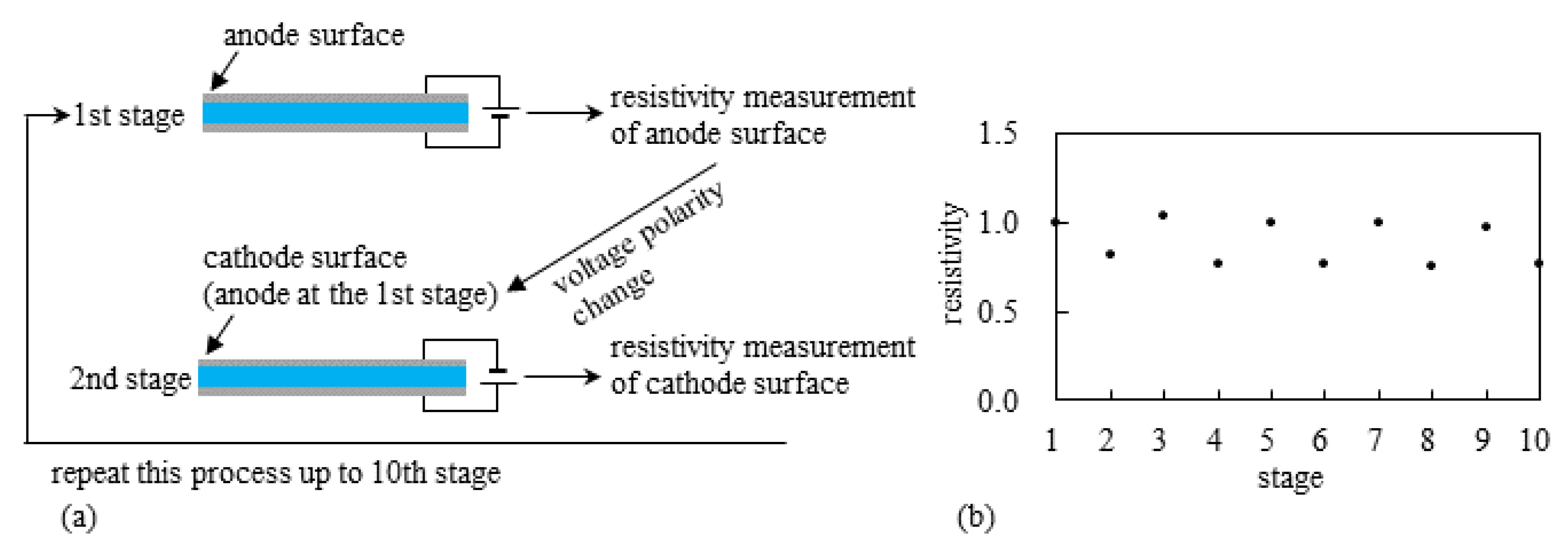
- Experiment (iv) The resistivity measurement of the silver coating of S-Naf and L-Naf was performed by the procedure illustrated in Figure 12a. 2 V was imposed on L-Naf for 100 s, then the anode surface resistivity was measured using four probe method as the 1st stage. Next, 2 V was again imposed on the same L-Naf with the reversed polarity for 100 s, and the resistivity of cathode surface (corresponding to the anode surface at the 1st stage) was measured as the 2nd stage. This process was repeated up to the 10th stage. The same measurement was performed for the S-Naf, too. The resistivity behavior of L-Naf is shown in Figure 12b. The data at the odd number stages represents the resistivity of the oxidized silver coating (anode), while the data at the even number stages represents the resistivity of the reduced silver coating (cathode). Clearly, the alternate increment and decrement of the resistivity was observed, which suggests the alternate induction of silver redox reaction. It was also true for S-Naf. Outcomes from the experiments of (ii), (iii) and (iv) suggest that the induction of silver redox reaction on the IPMC surface. What is described in this section suggests that the silver redox reaction is actually induced and it could even lead to the change of mechanical characteristics of the IPMC, . Consequently, such material characteristics change originating from the silver redox reaction could result in the simultaneous enhancement of bending and blocking force generation of the IPMC.
5.2. Selemion CMV-Based IPMC
5.2.1. Bending and Blocking Force under Constant Voltage
5.2.2. Bending and Blocking Force under the Constant Current
5.3. Structure of Thick Silver Layer on L-Naf
5.3.1. Role of the Thick Silver Coating for the Improvement of L-Naf Performance
5.3.2. Stick-Slip-Surface Treated IPMC
5.3.3. The Local Bending Curvature of IPMC
6. Conclusions
Author Contributions
Funding
Conflicts of Interest
Appendix A
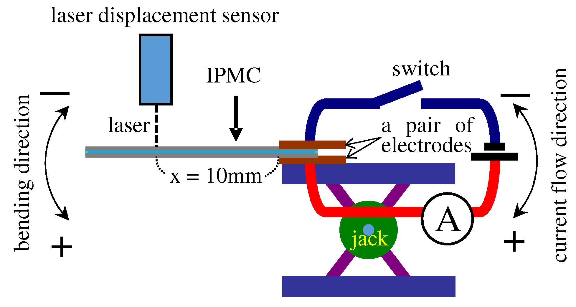
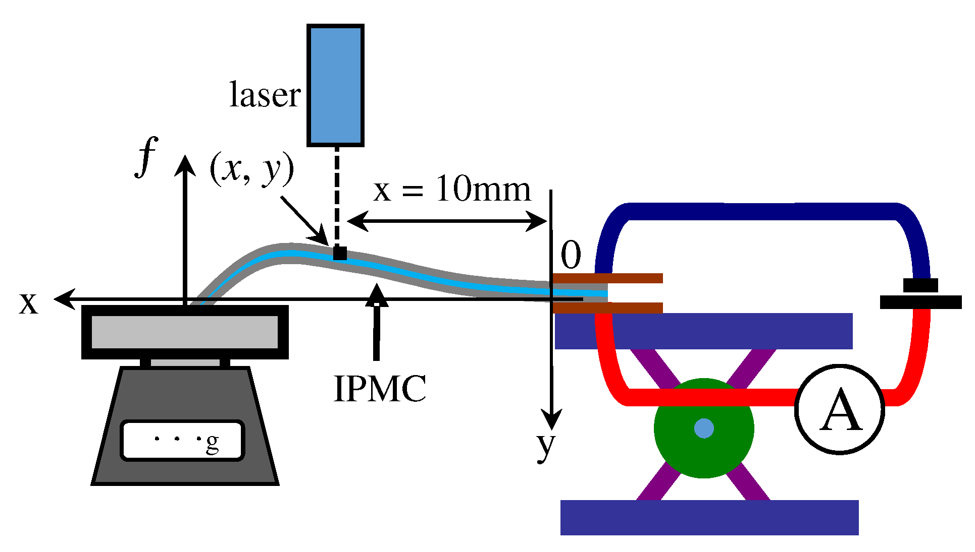
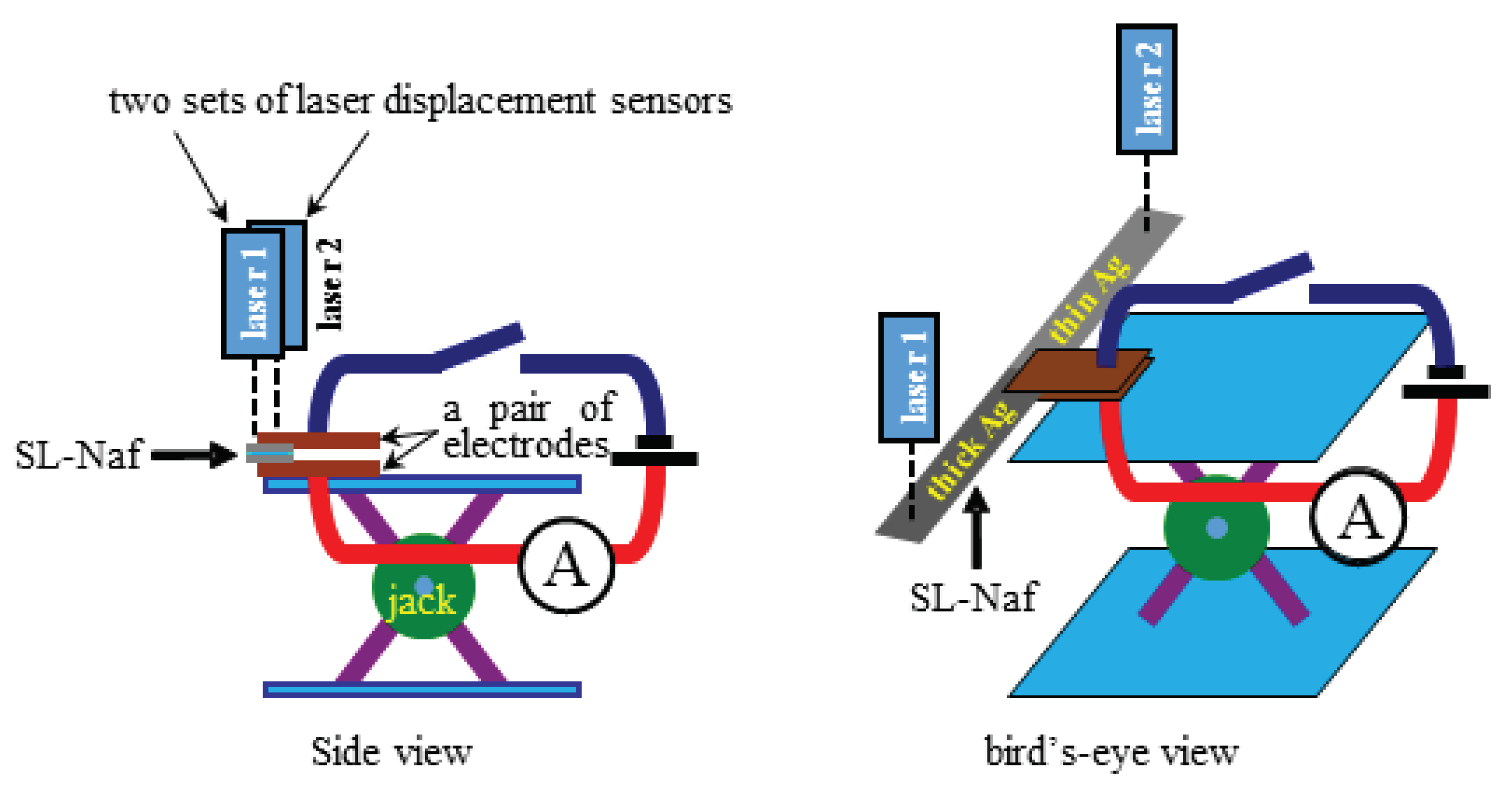
- 1st step: Blocking force, f, and the coordinate, (x, y), were measured simultaneously as a function of time. In this measurement, x was fixed at 10 mm as illustrated in Figure 5.
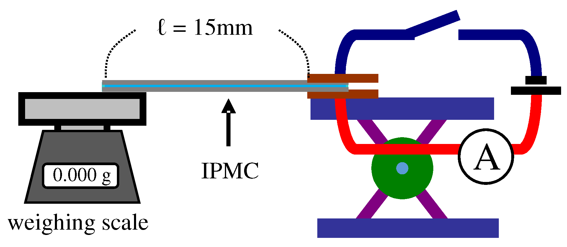
- 2nd step: Equation (A1) associates with and y [39]. They computed the time dependence of IPMC Young’s modulus using the experimental data of time-evolution of coordinate sets of ten representative points of IPMC. But we employed the coordinate set of single point of IPMC for simplicity. Thus, at first, we computationally obtained the formulas approximating the experimental data curve of “The single representative point coordinate (x = 10 mm, y) vs. Time”, where the formulas obtained is denoted by Y(t, x).: Laplace transformation, I: moment of inertia of area of IPMC, ℓ: ℓ = 15 mm, F(t): The definition is given in the 3rd step as below.
- 3rd step: We computationally obtained the formula of trendline approximating the experimental data curve of “Blocking force f vs. Time”, where the formula obtained is denoted by (p).
- 4th step: Plugging all the experimentally measured quantities of ℓ, x and I, and the computationally obtained formulas of (p,x) and (p) into Equation (A1), (p) is obtained. Performing the inverse Laplace transformation resulted in .
References
- Sandeep, O.S.; Padmanabhan, R. Design and Development of a Bi–Metallic Based Micro Pump. Int. J. Res. Mech. Eng. 2014, 2, 38–42. [Google Scholar]
- Chhabra, A.; Parkash, J.; Singh, A. A Study on Thermal Expansion Using Different Alloys for MEMS Actuators. Int. J. Res. Manag. Sci. Technol. 2015, 3, 133–136. [Google Scholar]
- Claeyssen, F.; Le Letty, R.; Barillot, F.; Sosnicki, O. Amplified Piezoelectric Actuators: Static & Dynamic Applications. Ferroelectrics 2007, 351, 3–14. [Google Scholar]
- Jänker, P.; Claeyssen, F.; Grohmann, B.; Christmann, M.; Lorkowski, T.; Le Letty, R.; Sosniki, O.; Pages, A. New Actuators for Aircraft and Space Applications. In Proceedings of the ACTUATOR 2008—11th International Conference on New Actuators, Bremen, Germany, 9–11 June 2008. [Google Scholar]
- Jang, S.; Lee, G.; Kim, H.; Ahn, K.; Park, J.; Ryew, S. Hydraulic Actuators in Application of Robot manipulator. In Proceedings of the 8th IEEE International Conference on Automation Science and Engineering, Seoul, Korea, 20–24 August 2012; pp. 924–925. [Google Scholar]
- Tanaka, T.; Nishio, I.; Sun, S.T.; Ueno-Nishio, S. Collapse of Gels under an Electric Field. Science 1982, 218, 467–469. [Google Scholar] [CrossRef] [PubMed]
- Osada, Y.; Okuzaki, H.; Hori, H. A Polymer Gel with Electrically Driven Motility. Nature 1992, 355, 242–244. [Google Scholar] [CrossRef]
- Otake, M.; Inaba, M.; Inoue, H. Kinematics of Gel Robots made of Electro-Active Polymer PAMPS Gel. In Proceedings of the 2000 IEEE International Conference on Robotics and Automation, San Francisco, CA, USA, 24–28 April 2000; pp. 488–493. [Google Scholar]
- Maeda, S.; Hara, Y.; Yoshida, R.; Hashimoto, S. Active Polymer Gel Actuators. Int. J. Mol. Sci. 2010, 11, 52–66. [Google Scholar] [CrossRef] [PubMed]
- Ionov, L. Hydrogel-based actuators: Possibilities and limitations. Mater. Today 2014, 17, 494–503. [Google Scholar] [CrossRef]
- Hara, S.; Zama, T.; Takashima, T.; Kaneto, K. Artificial Muscles Based on Polypyrrole Actuators with Large Strain and Stress Induced Electrically. Polym. J. 2004, 36, 151–161. [Google Scholar] [CrossRef]
- Choi, H.-J.; Song, Y.-M.; Chung, I.; Ryu, K.-S.; Jo, N.-J. Conducting polymer actuator based on chemically deposited polypyrrole and polyurethane-based solid polymer electrolyte working in air. Smart Mater. Struct. 2009, 18, 024006. [Google Scholar] [CrossRef]
- Yan, B.; Wu, Y.; Guo, L. Recent Advances on Polypyrrole Electroactuators. Polymer 2017, 9, 446. [Google Scholar] [CrossRef]
- O’Halloran, A.; O’Malley, F.; McHugh, P. A review on dielectric elastomer actuators, technology, applications, and challenges. J. Appl. Phys. 2008, 104, 071101. [Google Scholar] [CrossRef]
- Zhao, Z.; Shuai, C.; Gao, Y.; Rustighi, E.; Xuan, Y. An application review of dielectric electroactive polymer actuators in acoustics and vibration control. J. Phys. Confer. Ser. 2016, 744, 012162. [Google Scholar] [CrossRef]
- Bar-Cohen, Y. (Ed.) Electroactive Polymer (EAP) Actuators as Artificial Muscles: Reality, Potential, and Challenges; SPIE BOOK PRESS: Bellingham, WA, USA, 2004. [Google Scholar]
- Carrico, J.D.; Tyler, T.; Leang, K.K. A comprehensive review of select smart polymeric and gel actuators for soft mechatronics and robotics applications: Fundamentals, freeform fabrication, and motion control. Int. J. Smart Nano Mater. 2017, 8, 144–213. [Google Scholar] [CrossRef]
- Oguro, K.; Kawami, Y.; Takenaka, H. Bending of an ion-conducting polymer film-electrode composite by an electric stimulus at low voltage. Trans. J. Micromach. Soc. 1992, 5, 27–30. [Google Scholar]
- Oguro, K.; Asaka, K.; Takenaka, H. Polymer film actuator driven by low voltage. In Proceedings of the 4th International Symposium on Micro Machine and Human Science, Nagoya, Japan, 13–15 October 1993; pp. 39–40. [Google Scholar]
- Bar-Cohen, Y.; Xue, T.; Joffe, B.; Lih, S.-S. Electroactive polymers (EAP) low mass muscle actuators. Proc. SPIE 1997, 3041, 697–701. [Google Scholar]
- He, Q.; Yu, M.; Song, L.; Ding, H.; Zhang, X.; Dai, Z. Experimental Study and Model Analysis of the Performance of IPMC Membranes with Various Thickness. J. Bionic Eng. 2011, 8, 77–85. [Google Scholar] [CrossRef]
- He, Q.; Yu, M.; Yu, D.; Ding, Y.; Dai, Z. Significantly Enhanced Actuation Performance of IPMC by Surfactant-Assisted Processable MWCNT/Nafion Composite. J. Bionic Eng. 2013, 10, 359–367. [Google Scholar] [CrossRef]
- Park, J.H.; Lee, S.W.; Song, D.S.; Jho, J.Y. Highly Enhanced Force Generation of Ionic Polymer–Metal Composite Actuators via Thickness Manipulation. Appl. Mater. Interfaces 2015, 7, 16659–16667. [Google Scholar] [CrossRef] [PubMed]
- Kim, K.J.; Shahinpoor, M. Development of Three-Dimensional Polymeric Artificial Muscles. Proc. SPIE 2001, 4329, 223–232. [Google Scholar]
- He, Q.; Song, L.; Yu, M.; Dai, Z. Fabrication, characteristics and electrical model of an ionic polymer-metal carbon nanotube composite. Smart Mater. Struct. 2015, 24, 075001. [Google Scholar] [CrossRef]
- Trabia, S.; Hwang, T.; Kim, K.J. A fabrication method of unique Nafion® shapes by painting for ionic polymer-metal composites. Smart Mater. Struct. 2016, 25, 085006. [Google Scholar] [CrossRef]
- Asaka, K.; Oguro, K.; Nishimura, Y.; Mizuhara, M.; Takenaka, H. Bending of polyelectrolyte membrane-platinum composite by electric stimuli I, response characteristics to various waver forms. Polym. J. 1995, 27, 436–440. [Google Scholar] [CrossRef]
- Salehpoor, K.; Shahinpoor, M.; Mojarrad, M. Linear and platform type robotic actuators made from ion-exchange membrane-metal composites. Proc. SPIE 1997, 3040, 192–198. [Google Scholar]
- Shahinpoor, M.; Bar-Cohen, Y.; Xue, T.; Simpson, J.O.; Smith, J. Some Experimental Results on Ionic Polymer-Metal Composites (IPMC) As Biomimetic Sensors and Actuators. Proc. SPIE 1998, 3324, 245–267. [Google Scholar]
- Kim, S.-M.; Kim, K. Palladium buffer-layeredhigh performance ionic polymer-metal composites. Smart Mater. Struct. 2008, 17, 035011. [Google Scholar]
- Wang, Y.; Che, H.; Wanga, Y.; Zhu, Z.; Li, D. Effect of Dehydration on the Mechanical and Physicochemical Properties of Gold- and Palladium-Ionomeric Polymer-Metal Composite (IPMC) Actuators. Electrochim. Acta 2014, 129, 450–458. [Google Scholar] [CrossRef]
- Nishida, G.; Sugiura, M.; Maschke, B.; Ikeura, R. Multi-Input Multi-Output Integrated Ionic Polymer Metal Composite for Energy Control. Micromachines 2012, 3, 126–136. [Google Scholar] [CrossRef]
- Uchida, M.; Taya, M. Solid polymer electrolyte actuator using electrode reaction. Polymer 2001, 41, 9281–9285. [Google Scholar] [CrossRef]
- Biswal, D.K.; Nayak, B. Analysis of Time Dependent Bending Response of Ag-IPMC Actuator. Procedia Eng. 2016, 144, 600–606. [Google Scholar] [CrossRef]
- Tamagawa, H.; Nogata, F.; Popovic, S. Roles of Ag redox reaction and water absorption inducing the Selemion bending. J. Membr. Sci. 2005, 251, 145–150. [Google Scholar] [CrossRef]
- Tamagawa, H.; Nogata, F. Atomic structural change of silver-plating layers on the surfaces of Selemion, resulting in its excellent bending controllability. Sens. Actuators B Chem. 2006, 114, 781–787. [Google Scholar] [CrossRef]
- Tamagawa, H.; Nogata, F.; Sasaki, M. Charge quantity as a sole factor quantitatively governing curvature of Selemion. Sens. Actuators B Chem. 2007, 124, 6–11. [Google Scholar] [CrossRef]
- Onouchi, Y.; Sasaki, M.; Tamagawa, H. Current-controlled Selemion bending in the controlled humidity environment. Sens. Actuators B Chem. 2009, 135, 465–471. [Google Scholar] [CrossRef]
- Tamagawa, H.; Yagasaki, M.; Nogata, F. Mechanical characteristics of ionic polymer-metal composite in the process of self-bending. J. Appl. Phys. 2002, 92, 7614–7618. [Google Scholar] [CrossRef]
- Johanson, U.; Mäeorg, U.; Sammelselg, V.; Brandell, D.; Punning, A.; Kruusmaa, M.; Aabloo, A. Electrode reactions in Cu–Pt coated ionic polymer actuators. Sens. Actuators B Chem. 2008, 131, 340–346. [Google Scholar] [CrossRef]
- Wang, M.; Yu, M.; Lu, M.; He, Q.; Ji, K.; Liu, L. Effects of Cu2+ Counter Ions on the Actuation Performance of Flexible Ionic Polymer Metal Composite Actuators. J. Bionic Eng. 2018, 15, 1047–1056. [Google Scholar] [CrossRef]
- Naito, K.; Tsutsumi, T.; Yamada, T.; Yashiro, K. Processing method utilizing stick-slip phenomenon for formingperiodic micro/nano-structure. J. Mater. Process. Technol. 2016, 238, 267–273. [Google Scholar] [CrossRef]
- Naito, K.; Yamada, T.; Tsutsumi, T.; Yashiro, K. Wettability of a microgrid-structured polymer film with microfabrication utilizing the stick–slip phenomenon. J. Appl. Polym. Sci. 2017, 134, 45140. [Google Scholar] [CrossRef]








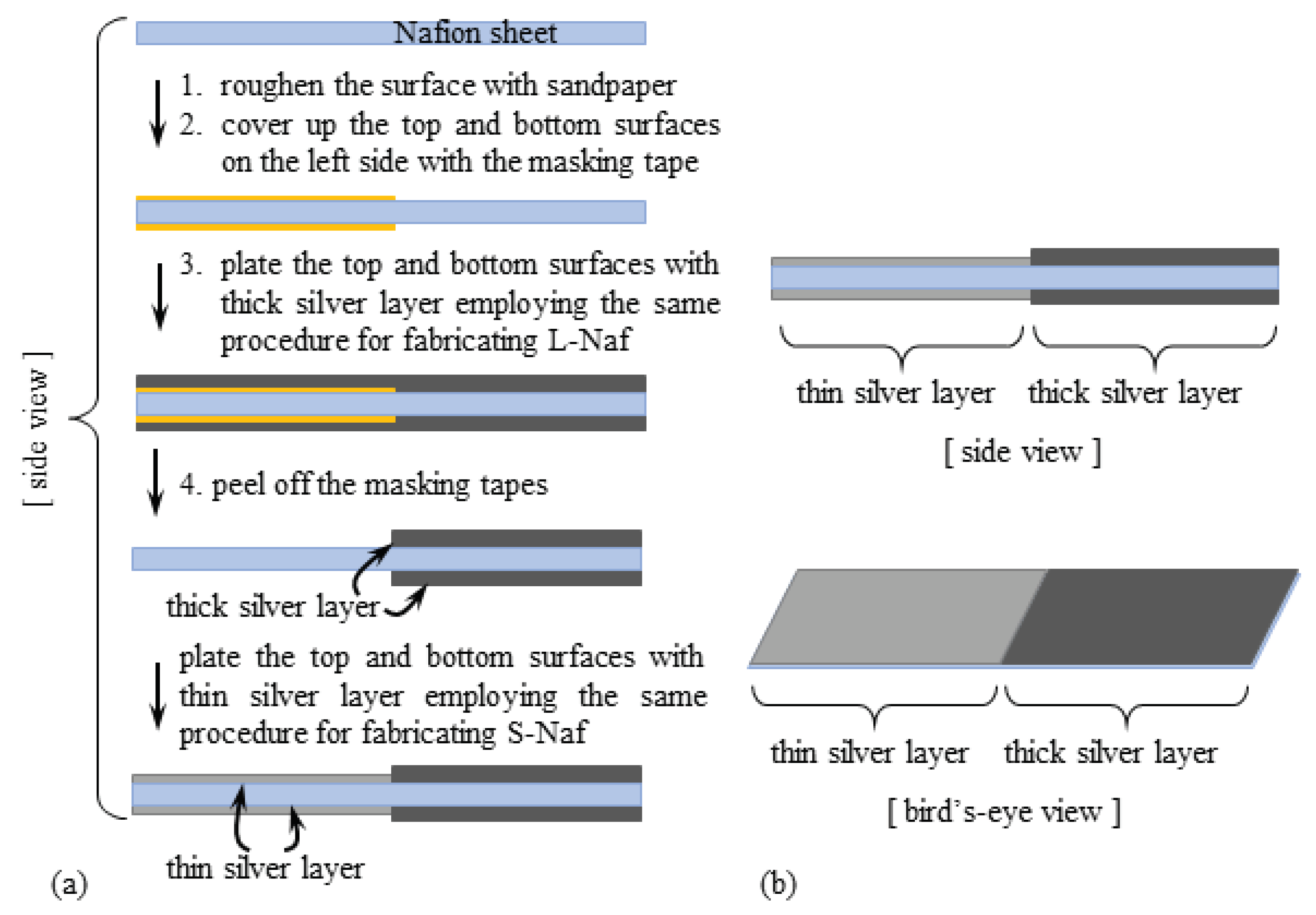

| Nafion-Based | Selemion CMV-Based | |
|---|---|---|
| thin (S) silver coatings thickness/μm | S-Naf | S-CMV |
| 188 | 192 | |
| thick (L) silver coatings thickness/μm | L-Naf | L-CMV |
| 208 | 205 | |
| thin & thick silver coatings thickness/μm | SL-Naf | - |
| 189–210 | - | |
| thick silver coatings thickness/μm | SS-Naf | - |
| 207 | - |
© 2019 by the authors. Licensee MDPI, Basel, Switzerland. This article is an open access article distributed under the terms and conditions of the Creative Commons Attribution (CC BY) license (http://creativecommons.org/licenses/by/4.0/).
Share and Cite
Tamagawa, H.; Okada, K.; Mulembo, T.; Sasaki, M.; Naito, K.; Nagai, G.; Nitta, T.; Yew, K.-C.; Ikeda, K. Simultaneous Enhancement of Bending and Blocking Force of an Ionic Polymer-Metal Composite (IPMC) by the Active Use of Its Material Characteristics Change. Actuators 2019, 8, 29. https://doi.org/10.3390/act8010029
Tamagawa H, Okada K, Mulembo T, Sasaki M, Naito K, Nagai G, Nitta T, Yew K-C, Ikeda K. Simultaneous Enhancement of Bending and Blocking Force of an Ionic Polymer-Metal Composite (IPMC) by the Active Use of Its Material Characteristics Change. Actuators. 2019; 8(1):29. https://doi.org/10.3390/act8010029
Chicago/Turabian StyleTamagawa, Hirohisa, Kazuki Okada, Titus Mulembo, Minoru Sasaki, Keishi Naito, Gakuji Nagai, Takahiro Nitta, Khai-Chun Yew, and Kota Ikeda. 2019. "Simultaneous Enhancement of Bending and Blocking Force of an Ionic Polymer-Metal Composite (IPMC) by the Active Use of Its Material Characteristics Change" Actuators 8, no. 1: 29. https://doi.org/10.3390/act8010029
APA StyleTamagawa, H., Okada, K., Mulembo, T., Sasaki, M., Naito, K., Nagai, G., Nitta, T., Yew, K.-C., & Ikeda, K. (2019). Simultaneous Enhancement of Bending and Blocking Force of an Ionic Polymer-Metal Composite (IPMC) by the Active Use of Its Material Characteristics Change. Actuators, 8(1), 29. https://doi.org/10.3390/act8010029


