Article

Simultaneous Enhancement of Bending and Blocking Force of an Ionic Polymer-Metal Composite (IPMC) by the Active Use of Its Material Characteristics Change

1
Department of Mechanical Engineering, Faculty of Engineering, Gifu University, 1-1 Yanagido, Gifu, Gifu 501-1193, Japan
2
Applied Physics Course, Gifu University, 1-1 Yanagido, Gifu, Gifu 501-1193, Japan
3
Department of Mechanical and Material Engineering, UTAR Sungai Long Campus, Jalan Sungai Long, Bandar Sungai Long, Cheras, Kajang 43000, Selangor, Malaysia
4
Graduate School of Advanced Mathematical Sciences, Meiji University, 4-21-1, Nakano, Nakano-ku, Tokyo 165-8525, Japan
*
Author to whom correspondence should be addressed.
Actuators 2019, 8(1), 29; https://doi.org/10.3390/act8010029
Submission received: 24 December 2018 / Revised: 14 March 2019 / Accepted: 15 March 2019 / Published: 25 March 2019

Abstract

:
The exhibition of significantly large bending is a remarkable characteristic of an ionic polymer-metal composite (IPMC). However, its inability to generate a high enough force is a major problem in achieving a practical IPMC actuator. The simultaneous enhancement of bending and force generation is needed for broadening the potential of the IPMC actuator as a practical engineering device. Corrosive materials as a flexible electrode of the IPMC is usually not preferred, whereas a noncorrosive material such as platinum is broadly used. Here, we used silver, a corrosive metal, as an IPMC electrode intentionally. The silver electrode exhibits a reversible redox reaction upon an external electric stimulation. That silver redox reaction resulted in the material characteristics change of the IPMC, and it consequently resulted in the simultaneous enhancement of the IPMC bending curvature and blocking force generation. It was further found that the thicker silver coating anchored into the far inside of the IPMC led to the occurrence of a significant silver redox reaction and it altered the material characteristics of the IPMC, consequently turning the IPMC into a greatly deformable and high force generative one.

1. Introduction

Actuators hold a pivotal place in the automotive industry, aviation industry, precision machinery industry, medical equipment and consumer electronics industry. Nowadays, various types of actuators are available such as bimetal actuators [1,2], piezoelectric actuators [3,4] and hydraulic actuators [5]. The existing actuators are essentially metal- or ceramic-based. Their deformations are precisely controllable and they are high force generative, too.
Electroactive polymer-based actuators such as hydrogels [6,7,8,9,10], conducting polymers [11,12,13], and dielectric elastomers [14,15] are categorized as soft actuators. Since their primary constituent material is polymer, their motion is quite flexible and similar to muscle motion unlike metal- and ceramic-based actuators. Therefore, the soft actuators are sometimes called artificial muscles [11,16,17].
Ionic polymer metal composite (IPMC), invented in the early 1990s, is also one of the electroactive polymers [18,19]. IPMC consists of a sheet of ion exchange membrane sandwiched between two flexible metal electrodes. This simply structured IPMC could exhibit a large deformation upon a low voltage [18,19]. Based on this, it was expected that the fabrication of a practical IPMC actuator could be achieved. However, it has remained unachieved up until today primarily due to the difficulty in realizing high force generation by the IPMC [20,21,22,23]. There have been some attempts of improving the IPMC force generation by thickening the individual components of IPMC (ion exchange membrane and electrode) [21,22,23], since it was theoretically expected that the improvement of the IPMC rigidity could lead to a higher force generation. However, the improvement of rigidity causes the side effect of diminishing the degree of bending as expected from the view of the strength of materials [24,25,26]. How can we solve this dilemma?
For the IPMC flexible electrode, platinum is usually used [17,18,19,20,21,22,23,24,25,26,27,28,29,30]. If not platinum, a chemically stable material such as gold (Au) is usually used [17,30,31,32]. In fact, the study of IPMCs bearing corrosive electrodes is rare, though not that such IPMC studies have never been done before [33,34,35,36,37,38]. We have been involved in the investigation of the IPMCs bearing silver (Ag) electrodes rather than platinum (Pt) electrodes for the past 20 years. The IPMC of an ion exchange membrane sheet sandwiched between two thin silver electrodes exhibits quite intriguing characteristics [35,36,37,38]. The IPMC of Selemion CMV (Selemion CMV is an ion exchange membrane manufactured by Asahi Galss Co. Ltd., Tokyo, Japan), sandwiched between two thin flexible silver electrodes, exhibits bending upon the imposition of only a few volts. We found that its large bending was always accompanied by a silver redox reaction, 2Ag + 1/2O 2 ⇌ Ag 2 O. The silver oxidation took place on the IPMC anode surface. The polarity change of the voltage caused the reduction of Ag 2 O into 2Ag and 1/2O 2 . So, a reversible silver redox reaction took place. It was also found that the induction of large bending requires a threshold imposed voltage, V t h [37]. The degree of IPMC bending abruptly increases once the voltage imposed on the IPMC reaches V t h . This strongly suggests that the silver redox reaction causes the IPMC large bending. Therefore, the IPMC material characteristics must have drastically changed at V t h , and consequently, the IPMC comes to exhibit a large bending.
Chemically stable and noncorrosive metal is usually preferred as a flexible electrode of IPMC, since the deterioration of the IPMC is unfavorable in every respect. Contrary to such a common notion, the active use of the unstable characteristics of IPMC components may be an effective tool for the induction of large bending and it could lead to the high blocking force generation, too. Using the unstable corrosive silver could bring us some benefits for the improvement of IPMC performance. It is expected that forming thick silver electrodes on the IPMC surfaces could cause the redox reaction of a large quantity of silver upon electric stimulation, resulting in the enhancement of the IPMC bending and force generation.
In this work, we fabricated both Nafion-based (Nafion is an ion exchange membrane manufactured by DuPont, Milwaukee, WI, USA) and Selemion CMV-based IPMCs bearing silver electrodes and quantitatively evaluated their bending and blocking force generation performance.

2. Specimen Preparation

2.1. Materials

Nafion- and Selemion CMV-based IPMCs were fabricated. Both contain -SO 3 H atomic group, but their structure is different from each other. The entire Nafion body consists of the random network of fluorocarbon chains bearing -SO 3 H groups as illustrated in Figure 1a. The main body of Selemion CMV is the hydrophobic polymer fabric and the fabric surface is coated with ion exchange resin containing -SO 3 H as in Figure 1b.

2.2. IPMCs with the Thin Silver Coating

The IPMCs having the thin silver coating were fabricated by the following procedure: The Nafion surface was roughened using sandpaper. After washing away the debris, it underwent the following silver mirror reaction: Two solutions respectively denoted as Sol-A and Sol-B were prepared. Sol-A consisted of silver nitrate (1.2 g), 17 N ammonium hydroxide (4 g) and deionized water (60 g). Sol-B consisted of d-(+)-glucose (0.8 g), NaOH (1.6 g) and deionized water (60 g). The surface-roughened Nafion sheet was submerged into 15 g of Sol-A for a few minutes. Subsequently, 15 g of Sol-B was added to it to induce the silver mirror reaction. The reaction ceased in several minutes, and the silver-plated Nafion sheet was washed with water in order to get rid of the silver debris. This silver plating process was repeated four times. The Selemion CMV-based IPMC was fabricated by plating its surface, and the procedure was same as that used for the plating of Nafion. Both resultant Nafion- and Selemion CMV-based IPMCs bore thin silver coatings serving as electrodes.

2.3. IPMCs with the Thick Silver Coating

A different type of IPMCs was fabricated. The surface roughened Nafion sheet was submerged into 15 g of Sol-A for 24 h so that the Sol-A permeated into the Nafion body from its surface. Then 15 g of Sol-B was added to it and left untouched for another 24 h. Then the resultant silver-plated Nafion was washed with water to get rid of the silver debris. This silver plating process was repeated four times. The silver layers appeared to be formed from the surface to a bit far inside of the Nafion body. Further, a fast silver plating treatment which is same as the procedure described in the Section 2.2, was repeated four times. So, the silver plating was performed eight times in total. The Selemion CMV underwent the same silver plating process, and thick silver coatings were formed on its surfaces. The resultant Nafion-based and Selemion CMV-based IPMCs bore thick silver coatings on their surfaces.

2.4. Storage of IPMCs

These IPMCs fabricated were stored in a desiccator with a desiccant for dehydration. The dehydrated Nafion- and Selemion CMV-based IPMCs were segmented into strips (20 mm in length and 2 mm in width). The strips of Nafion-based IPMC with thin and thick silver coatings were denoted as S-Naf and L-Naf, respectively. In the same manner, Selemion CMV-based IPMC strips with thin and thick silver coatings were denoted as S-CMV and L-CMV, respectively. The notations are summarized in Table 1 along with the thickness measured using the micrometer.

3. Prior Knowledge of the Dehydrated IPMC

Prior to detailing our study, the characteristics peculiar to our IPMC need to be explained. IPMC is usually electrically activated in the highly hydrated state. It is broadly accepted that the shift of mobile hydrated ions contained in the IPMC body under the applied voltage causes a gradient of the swelling ratio across the IPMC’s thickness direction, resulting in bending [32]. Therefore, the IPMC can even be electrically actuated in an aqueous solution on purpose [18,19]. Without hydration, the mobile hydrated ions are not generated in the IPMC body, and consequently, it is impossible to achieve the IPMC actuation. However, our IPMC was stored in a dry environment as detailed in the Section 2.4, and it absorbs only a minute quantity of water from the air, even when it is actuated. Because of this slight hydration, this conventional bending mechanism is not tenable for our IPMC bending. Nevertheless, the bending is induced by the imposition of voltage on the IPMC. We speculate that silver redox reaction is responsible for the bending of such a slightly hydrated IPMC [35,36,37,38]. We hypothesize that the silver redox reaction causes the atomic structural change of the silver coating and it could cause the bending [36].

4. Measurement

We take up the S-Naf in order to concisely explain the experiments we performed. IPMC can be electrically activated only when it contains a minimum amount of water. IPMC characteristics are quite susceptible to environmental humidity, since the IPMC absorbs water from the air [38]. All the specimens we fabricated absorbed water from the air when in use. Therefore, all the measurements shown in this paper were made along with monitoring the absolute humidity of the environment. Sometimes the experiments were performed in an environmental chamber in order to regulate the humidity condition, however we only used this a few times, since the precise humidity control is extremely difficult even when using the environmental chamber. The spatial distribution of such artificially generated humidity appears to be a bit heterogeneous compared to the naturally generated humidity, resulting in slightly different influences on the bending performance of IPMC compared with the naturally generated humidity. Therefore, we used the environmental chamber only when performing the experiments described in the Section 5.3.2. Since those experiments were performed in the winter, the environmental humidity was extremely low and IPMC could not be electrically activated. Hence, it was inevitably needed to raise the environmental humidity.
The threshold voltage of the silver redox reaction, V t h is dependent on the environmental absolute humidity. Based on our investigations of Nafion- and Selemion CNV-based IPMCs for years [35,36,37], we found that V t h is around 0.7 V as long as the absolute humidity is no less than 10 gm 3 . The typical way of determining V t h is described in the ref. [37]. All the experiments in this study except for one described in the Section 5.3.3 in this study were performed in the air with the absolute humidity equal to or greater than 10 gm 3 . Hence, throughout this work, V t h is 0.7 V for any IPMC specimen we fabricated.

4.1. Bending Test

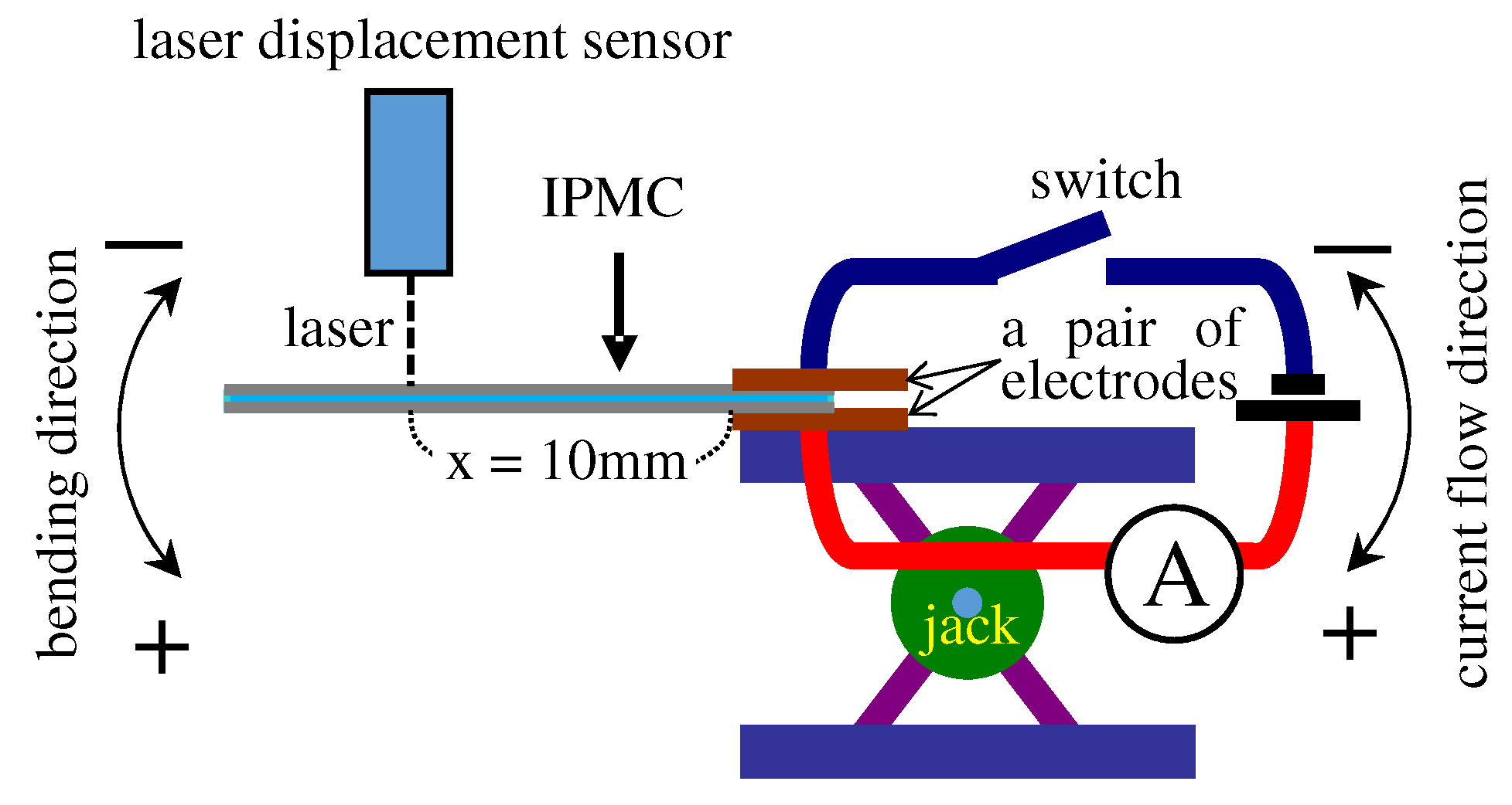
The S-Naf was horizontally clamped with a pair of electrodes as illustrated in Figure 2. Its vertical displacement under a constant voltage of 2 V was measured as a function of time using a laser displacement sensor. Simultaneously, the current was measured using an ammeter. The vertical displacement and current were later converted into curvature and charge, respectively. Next, the vertical displacement of S-Naf under a constant current of 0.1 mA was measured as a function of time.

4.2. Force Generation

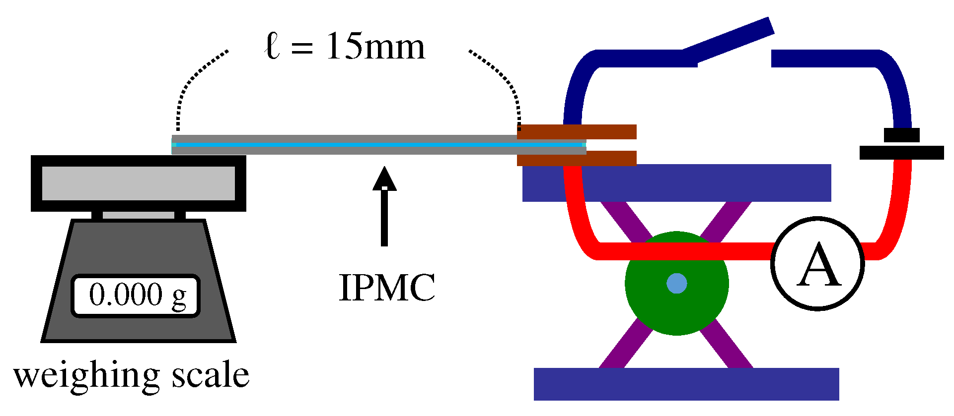
One end of the S-Naf was horizontally clamped with a pair of electrodes, and the tip was placed on the stage of a weighing scale as illustrated in Figure 3. The weighing scale acquired the blocking force generated by the downward bending of S-Naf under the constant voltage 2 V as a function of time, and simultaneously, the current induced was measured. Next, the blocking force generated by S-Naf under the constant current (not constant voltage) of 0.1 mA was measured as a function of time.
The same measurements described in the Section 4.1 and Section 4.2 were performed using L-Naf, S-CMV and L-CMV in place of S-Naf. All the experimental conditions for L-Naf were same as those for the S-Naf. But, for the S-CMV and the L-CMV, the imposed constant voltage was 1.5 V instead of 2 V and the imposed constant current was 0.35 mA instead of 0.1 mA.

4.3. Evaluation of the IPMC Bending Stiffness

The bending stiffness of S-Naf, L-Naf, S-CMV and L-CMV during the bending was evaluated. This evaluation procedure is detailed in the Section 5.1.1 and Appendix A.

4.4. Scrutinizing the Silver Layer Condition

As to be detailed in Section 5.1.1, we found that L-Naf exhibits both a large bending curvature and a high blocking force generation, and we speculated that the redox reaction of silver coatings on L-Naf played a pivotal role on enhancing both the bending curvature and the blocking force. Hence, we performed the following four measurements of L-Naf in order to know the state of the silver coating: (i) Cross-sectional observation of silver coating using SEM, (ii) EDX analysis of silver coating, (iii) Optical microscope observation of surface color of silver coating (note: the redox reaction of silver causes the color change “2Ag (white) + 1/2O 2 ⇌ Ag 2 O (black)”) and (iv) Measurement of silver coating resistivity using the four probe method. For comparison, the same analysis was performed for S-Naf.

5. Results and Discussion

5.1. Nafion-Based IPMC

5.1.1. Bending, Blocking Force and Bending Stiffness under the Constant Voltage

The time dependence of the bending curvature of S-Naf and L-Naf under 2 V is shown in Figure 4a, where the absolute humidity (AH) is given in the captions of individual diagrams from now on. The bending curvature of L-Naf is greater than that of S-Naf, despite the rigidity of L-Naf being greater than S-Naf because of their thickness difference (see Table 1). Figure 4b shows the time dependence of the blocking force of S-Naf and L-Naf under 2 V. The blocking force of L-Naf is also greater than that of S-Naf. The silver redox reaction took place for the measurements shown in Figure 4a,b, since the imposed voltage was greater than V t h (= 0.7 V).
The bending of a silver-coated IPMC is basically governed by the quantity of charge (or current) imposed on it [35,36,37,38]. The greater bending curvature of L-Naf than S-Naf as in Figure 4a suggests that the greater quantity of charge was generated in L-Naf than in S-Naf. This explains why the L-Naf, which is more rigid than S-Naf, exhibited a larger bending curvature than S-Naf. The greater bending curvature must lead to the greater blocking force. In fact, a greater blocking force by L-Naf more than that of S-Naf was observed as shown in Figure 4b. However, it is necessary to quantitatively verify if L-Naf is truly more rigid than S-Naf and if a greater quantity of charge was truly generated in L-Naf more than in S-Naf.
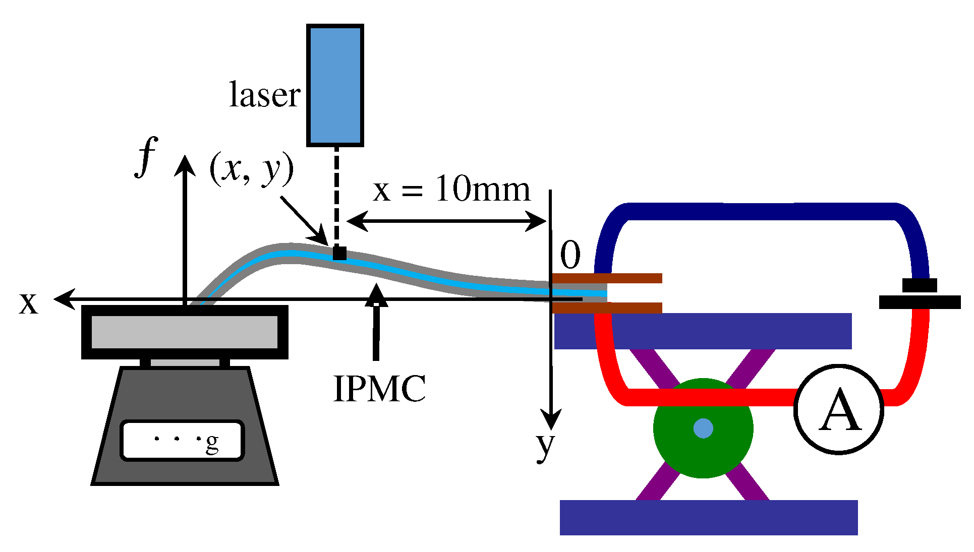
For the purpose of quantitatively evaluating the IPMC rigidity, the actual IPMC bending stiffness needs to be obtained. Since the IPMC is not structurally homogeneous, its Young’s modulus cannot be defined strictly speaking. Nevertheless, the moment of inertia of the area of the IPMC must basically be constant during bending. Hence, the bending stiffness can be approximately represented by E ¯ I where E ¯ and I are the representative value of Young’s modulus and the moment of inertia of the area of IPMC, respectively. Therefore, we can regard that the evaluation of E ¯ is equivalent to the evaluation of bending stiffness of E ¯ I . The representative value of Young’s modulus, E ¯ I , can be evaluated using the time evolution of the blocking force, f, and the coordinates of the representative point of the IPMC, (x, y), (see Figure 5). Therefore, we obtained the profile of E ¯ of the IPMC during the blocking force measurement. The procedure of obtaining E ¯ is essentially the same procedure developed by Tamagawa et al. [39], but we simplified it as explained in Appendix A. Figure 6 represents the E ¯ vs. Time of individual specimens. Here, L-Naf exhibits a drastic change of E ¯ over time, while the others do not. Further discussion of E ¯ behavior is given in the Section 5.1.3 and Section 5.2.1. Next, the charge quantity is evaluated. Figure 7 shows the time dependence of charge generated in L-Naf and S-Naf when the experiments for Figure 4a,b were performed. The charge Q(t) was obtained by numerically computing Equation (1), where the current, I(t), was experimentally measured using an ammeter equipped to the experimental setups (see Figure 2 and Figure 3). For both measurements of bending and blocking force, the quantity of charge generated in L-Naf was greater than that in S-Naf. Hence, it is quite understandable why the L-Naf exhibited greater bending curvature and greater blocking force than S-Naf, even though L-Naf is more rigid than S-Naf.
Q ( t ) = 0 t I ( τ ) d τ
Now, one question arises: If the imposition of a greater quantity of charge on the IPMC inevitably results in a greater bending and greater blocking force, there may be no need for going through great pains to fabricate a Nafion-based IPMC with “thick” silver coatings such as L-Naf. In fact, what needs to be done might be merely to impose a greater quantity of charge on the ordinary Nafion-based IPMC coated with “thin” silver like S-Naf. This issue is discussed in the next Section 5.1.2.

5.1.2. Bending and Blocking Force under the Constant Current

In order to settle the question raised in the previous section, the time dependence of the curvature of S-Naf and L-Naf under a constant current of 0.1 mA was measured, and the result is shown in Figure 8a. L-Naf exhibited a greater bending curvature than S-Naf even under the imposition of the same quantity of charge. The time dependence of the blocking force of S-Naf and L-Naf under the constant current of 0.1 mA is shown in Figure 8b and it shows that L-Naf exhibited a greater blocking force than S-Naf. So, L-Naf, which is mechanically more rigid than S-Naf according to Figure 6a, exhibited a greater bending curvature as well as a greater blocking force. It is understandable that the mechanically more rigid L-Naf generated higher blocking force than S-Naf. However, it is counterintutive that such a more mechanically rigid L-Naf exhibited the greater bending curvature than S-Naf by the impose of same quantity of charge. Figure 9 shows the time dependence of voltage generated when the experiments shown in Figure 8a,b were performed. Virtually, the voltage generated was beyond V t h for all the experiments. Therefore, silver redox reaction was inevitably induced for all the experiments performed under 0.1 mA current. The occurrence of the silver redox reaction suggests that the variation of the atomic structure of the silver coatings of the IPMC [36], and which could result in the change of mechanical characteristics of the IPMC of L-Naf as shown in Figure 6a. Such mechanical characteristics change must have led to the simultaneous enhancement of bending and blocking force generation of L-Naf. Therefore, the use of a corrosive metal like silver as an electrode material is not necessarily unbeneficial to the IPMC performance. The change of the material characteristics of IPMC by using a less stable and corrosive material is one of the strong tools for the improvement of IPMC performance. But why didn’t E ¯ of S-Naf have as large of a change as L-Naf? In the next section, it will be discussed.

5.1.3. Characteristics of the Silver Layer

The silver layer on the IPMC surface connected to the positive terminal of power supply exhibits an oxidation 2Ag + 1/2O 2 → Ag 2 O, while the reversal of polarity induces a reduction 2Ag + 1/2O 2 ← Ag 2 O. This redox reaction is accompanied by the atomic structural change of the silver layers [36], and it must have played a pivotal role in enhancing both the bending curvature and the blocking force. Hence, we performed the following four different experiments described in the Section 4.4 in order to scrutinize the silver layer state.
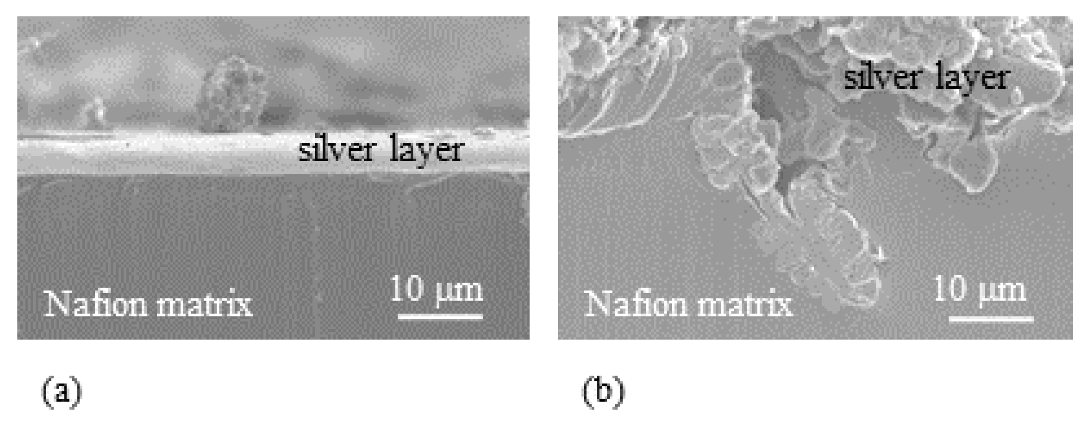
  • Experiment (i) Since the averaged thickness of L-Naf is 208 μ m and that of S-Naf is 188 μ m as summarized in Table 1, the silver coating of L-Naf is 10 μ m thicker than that of S-Naf based on the simple calculation (208 μ m − 188 μ m) ÷ 2 = 10 μ m. However, the SEM images in Figure 10 show that the silver layer of L-Naf penetrates a bit far inside of Nafion body, the penetration depth of silver is not included in that 10 μ m, while the silver layer of S-Naf is formed merely on the Nafion surface.
    In addition to the SEM images shown in Figure 10, we obtained the following outcomes concerning the above-described experiments, (ii), (iii) and (iv).
  • Experiment (ii) We found that the mass ratio of silver to oxygen in the oxidized silver coating of L-Naf was 6:1, while that of the reduced silver coating was 20:1. This EDX result suggests that the voltage impose and its polarity change causes the characteristic change of L-Naf, and it is true for S-Naf, too.
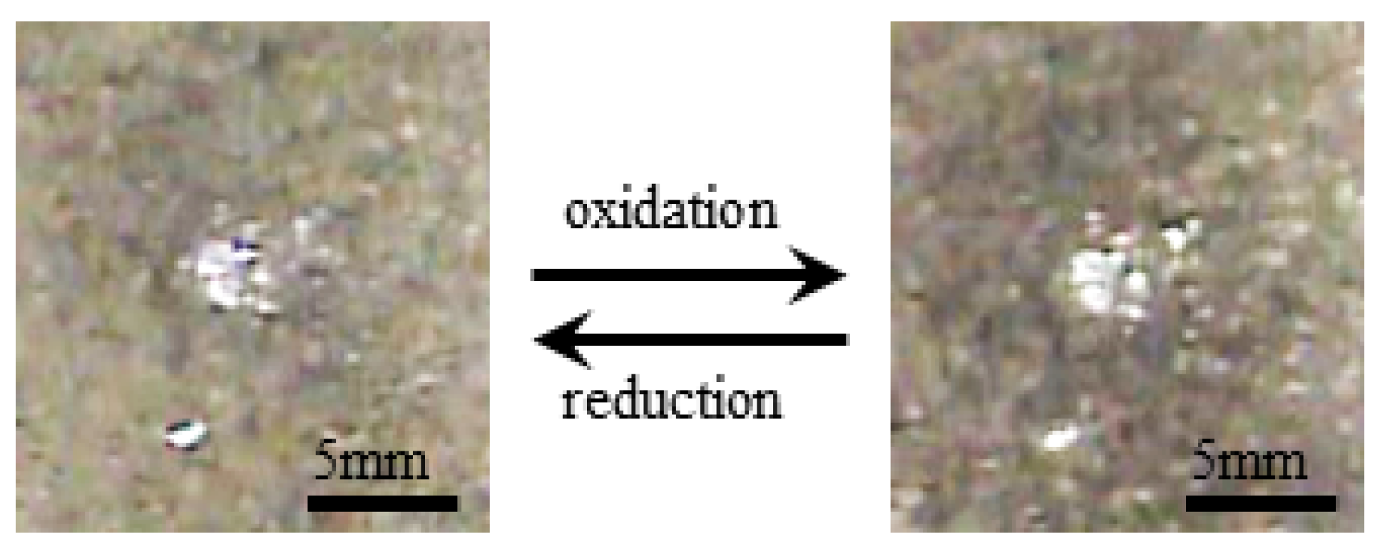
  • Experiment (iii) Upon the voltage imposed on S-Naf and L-Naf, the color of their anode surface changed from bright white to a slight dark brown due to the oxidation of silver into silver dioxide. The polarity change of voltage resulted in the change of dark brown surface back into to the initial bright white surface due to the reduction of silver dioxide into silver. Figure 11 shows the typical surface color change of L-Naf by the redox reaction.
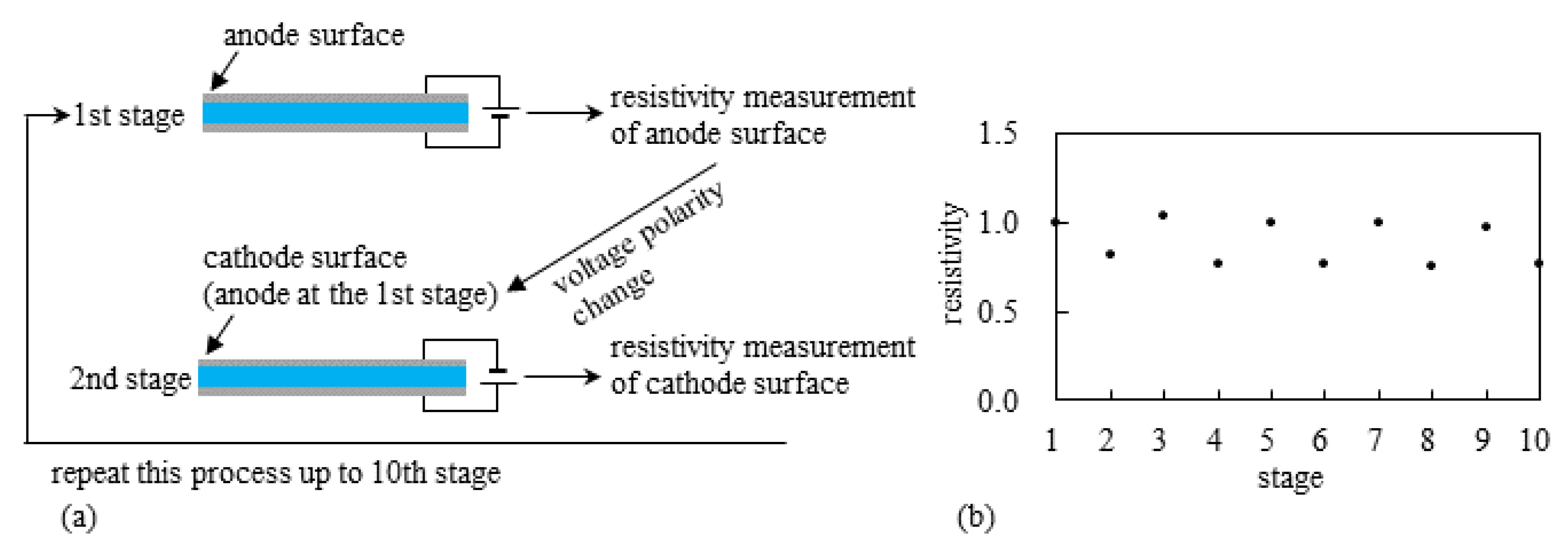
  • Experiment (iv) The resistivity measurement of the silver coating of S-Naf and L-Naf was performed by the procedure illustrated in Figure 12a. 2 V was imposed on L-Naf for 100 s, then the anode surface resistivity was measured using four probe method as the 1st stage. Next, 2 V was again imposed on the same L-Naf with the reversed polarity for 100 s, and the resistivity of cathode surface (corresponding to the anode surface at the 1st stage) was measured as the 2nd stage. This process was repeated up to the 10th stage. The same measurement was performed for the S-Naf, too. The resistivity behavior of L-Naf is shown in Figure 12b. The data at the odd number stages represents the resistivity of the oxidized silver coating (anode), while the data at the even number stages represents the resistivity of the reduced silver coating (cathode). Clearly, the alternate increment and decrement of the resistivity was observed, which suggests the alternate induction of silver redox reaction. It was also true for S-Naf. Outcomes from the experiments of (ii), (iii) and (iv) suggest that the induction of silver redox reaction on the IPMC surface. What is described in this section suggests that the silver redox reaction is actually induced and it could even lead to the change of mechanical characteristics of the IPMC, E ¯ . Consequently, such material characteristics change originating from the silver redox reaction could result in the simultaneous enhancement of bending and blocking force generation of the IPMC.
Why did the impose of the same quantity of charge on the S-Naf and the L-Naf result in the greater bending curvature of L-Naf than that of S-Naf as shown in Figure 8a? As to L-Naf, it is attributed to “(I) the greater quantity of silver on the L-Naf surface than on S-Naf” and to “(II) the penetration of silver into a bit far inside of Nafion matrix of L-Naf as seen in Figure 10”. Concerning (I), the greater quantity of silver of L-Naf was involved in the redox reaction, since L-Naf silver coating is thicker than that of S-Naf. This leads to the more significant characteristics change of the L-Naf than the S-Naf, and consequently, resulting in the significant enhancement of bending and blocking force generation. Concerning (II), penetration of the silver coating into a bit far inside of the Nafion matrix positions the silver atoms and -SO 3 H groups at closer range to each other. The -SO 3 H groups serve as a sort of supportive electrolyte. Therefore, the silver redox reaction is highly promoted in the L-Naf. For the reasons (I) and (II), the redox reaction of the greater quantity of silver on the L-Naf was highly enhanced and more effectively influenced on the material characteristics change of L-Naf than those of S-Naf. Therefore, the L-Naf exhibited the greater bending and the greater blocking force than S-Naf. Such behavioral difference between L-Naf and S-Naf is also observed in the te representative value of Young’s modulus behavior, too. Why does the L-Naf exhibit the drastic change of E ¯ with time, while the S-Naf does not? (This question was raised at the end of the previous section). Because the redox reaction of silver is highly promoted in the L-Naf than the S-Naf, it is significantly reflected in the material characteristics change of L-Naf. However, the smaller quantity of silver which was not far inside of S-Naf was unable to significantly contribute to the induction of the material characteristics change of S-Naf. The fundamental importance of the penetration of electrode metal into the ion exchange matrix for the enhancement of the IPMC bending was recognized soon after the invention of IPMC [20,22,29]. However, those works refer to the electrical conductivity of electrode and the noncorrosive electrodes were used. Our emphasis does not lie in the electrode electrical conductivity but rather in the intentionally-induced silver redox reaction and the material characteristics change of the IPMC such as the atomic structural change of silver coating [36].

5.2. Selemion CMV-Based IPMC

5.2.1. Bending and Blocking Force under Constant Voltage

Figure 13a shows the time dependence of the bending curvature of the S-CMV and the L-CMV under 1.5 V. The silver layer of the L-CMV was thicker than that of the S-CMV, and the L-CMV exhibited slightly smaller bending than the S-CMV. As reported before, the IPMC comprising Selemion CMV sandwiched between the silver coatings exhibits a proportional relationship between its bending curvature and the total charge imposed on it [37,38]. Thus, we rearranged the curvature data shown in Figure 13a into the curvature vs. total charge as shown in Figure 14a. Both curves of the S-CMV and the L-CMV form an almost same data curve. Next, Figure 13b shows blocking force vs. time of the S-CMV and the L-CMV under 1.5 V. Figure 13b is rearranged into blocking force vs. charge as shown in Figure 14b. According to Figure 13a, the L-CMV appeared to be slightly less deformable than the S-CMV, while Figure 14b shows that the blocking force by L-CMV was a bit greater than that by the S-CMV. This result could be attributed to the slightly greater mechanical strength of the L-CMV than that of S-CMV, that is, as predicted using the strength of materials, the slightly more rigid L-CMV exhibited slightly smaller bending curvature and greater blocking force than S-CMV. The measurement of the representative value of Young’s modulus, E ¯ , of S-CMV and L-CMV was performed using the same procedure employed for the S-Naf and the L-Naf. Contrary to our speculation, E ¯ of L-CMV was about half of E ¯ of the S-CMV as shown in Figure 6b. Selemion CMV comprises a polymeric fabric coated with ion exchange resin as illustrated in Figure 1b. So, in the silver plating treatment, not the whole body of Selemion CMV absorbed the Sol-A but only the thin ion exchange resin layers did. Hence, the repetition of the silver plating process did not result in the formation of a thick silver coating which well penetrated into the Selemion CMV matrix but merely resulted in the accumulation of silver particles on the Selemion CMV surfaces. The silver particles that merely accumulated on the L-CMV could not enhance the L-CMV mechanical strength. Nevertheless, we computed the moment of inertia of area of the L-CMV using the thickness of the L-CMV including the silver layer thickness. It could result in the underestimation of E ¯ of the L-CMV. We recomputed E ¯ of the L-CMV under the assumption that the effective thickness of L-CMV is same as that of the S-CMV and obtained the result represented by the dashed line in Figure 6b. It is quantitatively only a bit greater than E ¯ of S-CMV. This result is in line with the experimental results that L-CMV is slightly less deformable than S-CMV as shown in Figure 13a and the blocking force by the L-CMV is a bit greater than that by the S-CMV as shown in Figure 13b. However, what is fundamentally important does not lie in the precise estimation of E ¯ but rather in the precise estimation of the trend of E ¯ against time. Figure 6 suggests that only L-Naf exhibits a drastic change of E ¯ . Changeable material characteristics must be fundamentally necessary to achieve the simultaneous enhancement of bending and blocking force generation of the IPMC. With little changeable material characteristics, significant simultaneous enhancement of bending and blocking force generation can not be expected.

5.2.2. Bending and Blocking Force under the Constant Current

Figure 15a,b show curvature vs. charge and blocking force vs. charge of S-CMV and L-CMV under 0.35 mA, respectively. Figure 15a suggests that L-CMV is, as expected, slightly less deformable than S-CMV in response to the charge imposed. On the other hand, the L-CMV generated slightly greater blocking force than the S-CMV. Figure 14 and Figure 15 are interpreted that the rigid L-CMV is slightly less deformable than S-CMV but is able to generate a bit greater blocking force than S-CMV. So, the use of Selemion CMV as a matrix of IPMC does not result in the creation of an IPMC which can simultaneously suffice the exhibition of large deformation and high blocking force generation, even though the large quantity of silver is accumulated on the Selemion CMV surface.

5.3. Structure of Thick Silver Layer on L-Naf

So far, it is shown that the induction of the silver redox reaction could result in an atomic structural change and it could lead to the improvement of bending and blocking force generation of IPMC. Redox reaction of metal coating of IPMC is not so unusual phenomenon. Johanson et al. observed the creation and loss of copper layer of the copper-platinum plated Nafion IPMC during the actuation [40]. Wang et al. performed the cyclic voltammetry of the IPMC contiaining Cu 2 + and confirmed the occurrence of redox reaction Cu ⇌ Cu + 2e [41]. Uchida and Taya fabricated an IPMC by plating a Nafion with copper and platinum. They achieved a large bending and at the same time observed the occurrence of reversible creation and loss of copper layer by the polarity change of voltage imposed on the IPMC even about two decades ago [33]. Although Uchida and Taya still attributed the large IPMC bending to the shift of mobile hydrated Cu 2 + , we think that it is significantly owing to the atomic structural change of copper layer. Kim et al. fabricated an IPMC coated with platinum and palladium (no copper) and observed the simultaneous enhancement of bending and blocking force generation [30]. They observed the occurrence of redox reaction of platinum on the IPMC surface by mean of the cyclic voltammetry, although the cyclic voltammmetry was performed for the IPMC in 0.5 M H 2 SO 4 aqueous solution and it was different condition from those employed for the bending and blocking force measurements. Kim et al. appeared to notice some influence of redox reaction of platinum component in the electrode on the IPMC performance, but they did not provide the mechanism how the platinum redox reaction lead to the simultaneous enhancement of bending and blocking force generation.
Our IPMC does not contain copper or platinum, but the occurrence of metal layer redox reaction can easily take place. We come to notice that even more active use of redox reaction of silver coating could significantly improve the IPMC performance and broaden its potential usefulness. With such notions in mind, we performed the further investigations described below.

5.3.1. Role of the Thick Silver Coating for the Improvement of L-Naf Performance

The thicker silver coating of the L-Naf appears to play a pivotal role in its displaying of the advantageous characteristics. However, merely forming a thicker silver layer on the IPMC does not necessarily lead to the simultaneous enhancement of bending and force generation as indicated by the experimental results for S-CMV and L-CMV so far shown. It was speculated earlier that the structural relationship between the silver and -SO 3 H groups ion exchange membrane (Nafion) is one of the fundamental factors for the induction of unusually superb performance of L-Naf. Figure 16a illustrates the cross-sectional view of L-Naf. The silver coating was formed from the Nafion surface into far inside of the Nafion body. Figure 16b illustrates the cross-sectional view of L-CMV. The silver of L-CMV does not penetrate into far inside of the Selemion CMV body. Most of the silver of the L-CMV is merely accumulated on the Selemion CMV surfaces. Bearing that in mind, we propose an idea for an effectively deformable and simultaneously effectively force generative IPMC: Achieving the deeper penetration of silver layer into the ion exchange membrane body could result in an IPMC which can exhibit the effective bending and higher force generation.

5.3.2. Stick-Slip-Surface Treated IPMC

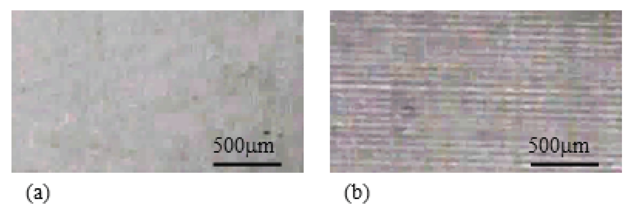
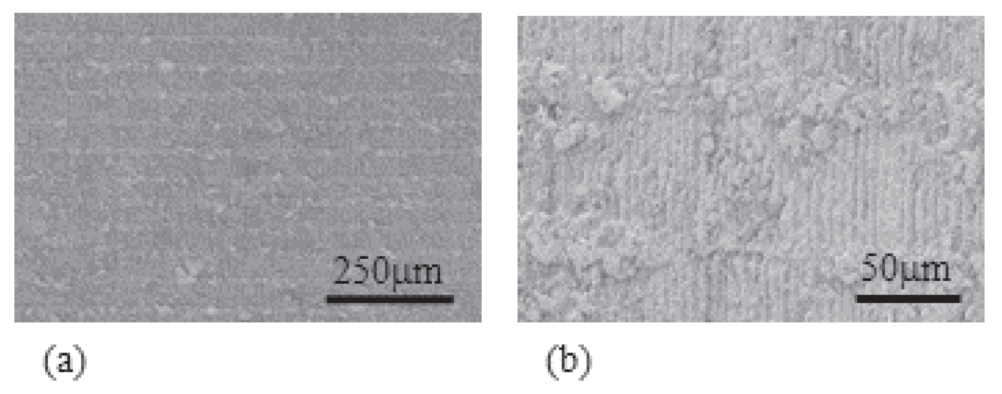
Although it is suggested in the previous section that the formation of a thicker silver coating from the Nafion surface toward the significantly far inside of the Nafion body could result in the quite effective simultaneous bending and blocking force generation, it is not easy to put it in practice. As a trial, we performed the scathing of Nafion surface through the stick-slip micro level surface treatment [42,43]. Figure 17a shows the non-treated surface of Nafion. Using the stick-slip surface treatment, Nafion came to have a number of micro level grooves as shown in Figure 17b. Notice that those grooves are usually invisibly fine and shallow and it is not clearly visible even by electron microscope. The visible grooves in the optical microscope photo of Figure 17b is owing to the right lighting. The same silver plating treatment for the L-Naf fabrication was performed for this stick-slip surface-treated Nafion. The resulting IPMC is denoted by SS-Naf. Although the grooves formed on the Nafion surface before the silver plating are not so clearly visible by the electron microscope observation, the embedment of silver in those grooves are clearly seen as shown in Figure 18.
Bending and blocking force measurements were performed for SS-Naf. The experimental results are shown in Figure 19 and Figure 20. For comparison, the same experiments were performed for the L-Naf, too, and the experimental outcomes are given in Figure 19 and Figure 20. These diagrams suggest that the performance of SS-Naf by far exceeds that of L-Naf. (Attention: The bending and blocking force behaviors of L-Naf shown in Figure 19 and Figure 20 are a bit different from those shown in Figure 4 and Figure 8. It is primarily due to the environmental humidity difference and the use of environmental chamber as described at the beginning of the Section 4).

5.3.3. The Local Bending Curvature of IPMC

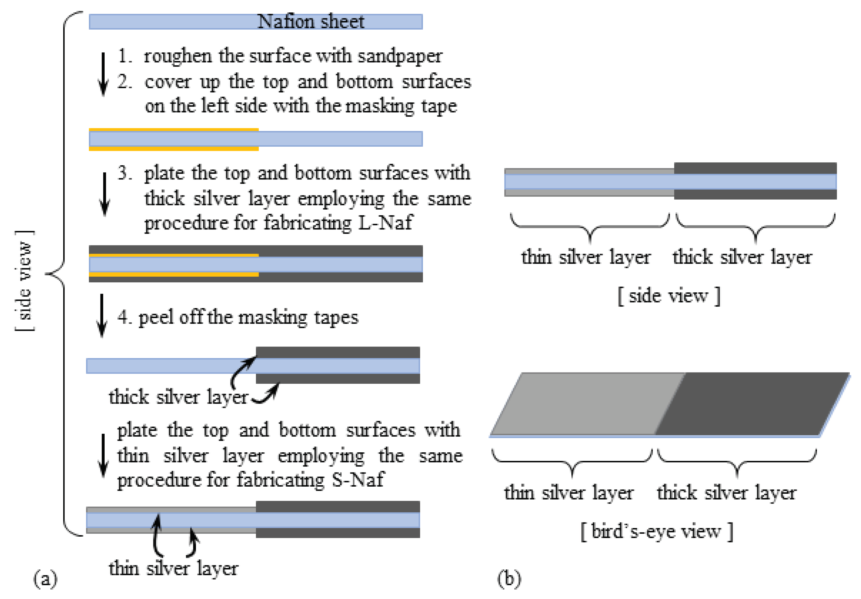
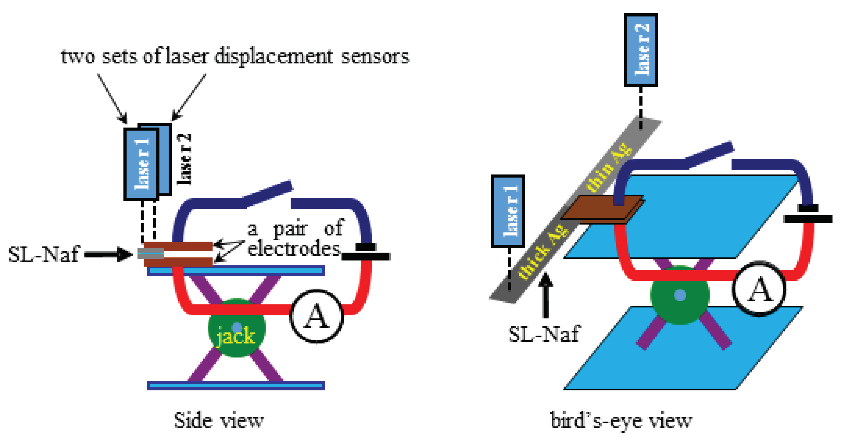
If the thickness of the silver coatings on the Nafion surfaces played a fundamental role in bending and blocking force generation, we speculated that the locally different degree of bending in a single piece of Nafion-based IPMC is achievable by controlling the local thickness of the silver coating. If this speculation is verified, “silver coating thickness control” could become a tool for fabricating ununiformly-deformable IPMCs. We performed the following verification tests: A strip of Nafion-based IPMC was prepared. One half of its surface was covered with a thick silver coating and the rest of the surface was covered with a thin silver coating. The fabrication procedure is exactly described as shown in Figure 21, where the resultant IPMC is hereafter called SL-Naf (see Table 1). The central part of SL-Naf was clamped between a pair of electrodes, and the vertical displacement of SL-Naf under the voltage imposed was measured using the laser displacement sensors as a function of time using the setup illustrated in Figure 22. Laser 1 detects the vertical displacement of the thick silver coating part of SL-Naf, while Laser 2 detects the vertical displacement of the thin silver coating part of the same SL-Naf. We performed the same measurement using the specimen of S-Naf. We refrained from using the environmental chamber, since the absolute humidity was around 8 gm 3 , which is below 10 gm 3 but not extremely low for the IPMC testing and the induction of silver redox reaction was well-expected due to the high enough imposed voltage.
The measured vertical displacement was computed into the bending curvature as shown in Figure 23. The bending curvature of the thick silver coating part of the SL-Naf is greater than that of the thin silver coating part. The bending curvatures of the S-Naf detected by Laser 1 and Laser 2 behaved quite similarly. Furthermore, the bending curvature of thin silver coating part of the SL-Naf represented by the symbol “+” in Figure 23 was quite similar to those bending curvature behaviors of S-Naf represented by the symbols “∘” and “•”, while the bending curvature of thick silver coating part of the SL-Naf represented by the symbol “×” was by far greater than the bending curvatures of the others.

6. Conclusions

We found that the enhancement of bending and force generation of the silver-plated Nafion IPMC could be simultaneously achieved simply by forming a thick silver coating on the Nafion surface. But it is necessary to form the silver coating at the far inside of the Nafion body away from the surfaces. Simply piling up the thick silver coating on the Nafion surface does not work well. We proposed an idea of a new IPMC which could exhibit both effective bending and force generation. We also experimentally confirmed that the degree of bending of the silver-coated Nafion IPMC is controllable by adjusting the thickness of silver coatings. These improvements of IPMC performance owes primarily to the active use of redox reaction of silver coating. The redox reaction leads to the drastic change of IPMC’s characteristics, resulting in the broadening of potential usefulness of IPMC as a soft actuator.

Author Contributions

H.T. conceived this work. H.T., K.O., T.M., K.N. and K.-C.Y. performed the experiments. K.I. performed the theoretical analysis and computation. G.N. checked the validity of theory. H.T. wrote the draft. T.M., K.N. and T.N. checked the logic described in the draft. M.S. and T.N. are the supervisors of T.M.

Funding

This research received no external funding.

Conflicts of Interest

The authors declare no conflict of interest.

Appendix A

Computational procedure of the representative value of Young’s modulus, E ¯
  • 1st step: Blocking force, f, and the coordinate, (x, y), were measured simultaneously as a function of time. In this measurement, x was fixed at 10 mm as illustrated in Figure 5.
  • 2nd step: Equation (A1) associates E ¯ ( t ) with f and y [39]. They computed the time dependence of IPMC Young’s modulus using the experimental data of time-evolution of coordinate sets of ten representative points of IPMC. But we employed the coordinate set of single point of IPMC for simplicity. Thus, at first, we computationally obtained the formulas approximating the experimental data curve of “The single representative point coordinate (x = 10 mm, y) vs. Time”, where the formulas obtained is denoted by Y(t, x).
    Y ^ ( p , x ) = F ^ ( p ) x 2 ( x ) 6 p E ^ ( p ) I
    ^ : Laplace transformation, I: moment of inertia of area of IPMC, : = 15 mm, F(t): The definition is given in the 3rd step as below.
  • 3rd step: We computationally obtained the formula of trendline approximating the experimental data curve of “Blocking force f vs. Time”, where the formula obtained is denoted by F ^ (p).
  • 4th step: Plugging all the experimentally measured quantities of , x and I, and the computationally obtained formulas of Y ^ (p,x) and F ^ (p) into Equation (A1), E ^ (p) is obtained. Performing the inverse Laplace transformation resulted in E ¯ ( t ) .

References

  1. Sandeep, O.S.; Padmanabhan, R. Design and Development of a Bi–Metallic Based Micro Pump. Int. J. Res. Mech. Eng. 2014, 2, 38–42. [Google Scholar]
  2. Chhabra, A.; Parkash, J.; Singh, A. A Study on Thermal Expansion Using Different Alloys for MEMS Actuators. Int. J. Res. Manag. Sci. Technol. 2015, 3, 133–136. [Google Scholar]
  3. Claeyssen, F.; Le Letty, R.; Barillot, F.; Sosnicki, O. Amplified Piezoelectric Actuators: Static & Dynamic Applications. Ferroelectrics 2007, 351, 3–14. [Google Scholar]
  4. Jänker, P.; Claeyssen, F.; Grohmann, B.; Christmann, M.; Lorkowski, T.; Le Letty, R.; Sosniki, O.; Pages, A. New Actuators for Aircraft and Space Applications. In Proceedings of the ACTUATOR 2008—11th International Conference on New Actuators, Bremen, Germany, 9–11 June 2008. [Google Scholar]
  5. Jang, S.; Lee, G.; Kim, H.; Ahn, K.; Park, J.; Ryew, S. Hydraulic Actuators in Application of Robot manipulator. In Proceedings of the 8th IEEE International Conference on Automation Science and Engineering, Seoul, Korea, 20–24 August 2012; pp. 924–925. [Google Scholar]
  6. Tanaka, T.; Nishio, I.; Sun, S.T.; Ueno-Nishio, S. Collapse of Gels under an Electric Field. Science 1982, 218, 467–469. [Google Scholar] [CrossRef] [PubMed]
  7. Osada, Y.; Okuzaki, H.; Hori, H. A Polymer Gel with Electrically Driven Motility. Nature 1992, 355, 242–244. [Google Scholar] [CrossRef]
  8. Otake, M.; Inaba, M.; Inoue, H. Kinematics of Gel Robots made of Electro-Active Polymer PAMPS Gel. In Proceedings of the 2000 IEEE International Conference on Robotics and Automation, San Francisco, CA, USA, 24–28 April 2000; pp. 488–493. [Google Scholar]
  9. Maeda, S.; Hara, Y.; Yoshida, R.; Hashimoto, S. Active Polymer Gel Actuators. Int. J. Mol. Sci. 2010, 11, 52–66. [Google Scholar] [CrossRef] [PubMed]
  10. Ionov, L. Hydrogel-based actuators: Possibilities and limitations. Mater. Today 2014, 17, 494–503. [Google Scholar] [CrossRef]
  11. Hara, S.; Zama, T.; Takashima, T.; Kaneto, K. Artificial Muscles Based on Polypyrrole Actuators with Large Strain and Stress Induced Electrically. Polym. J. 2004, 36, 151–161. [Google Scholar] [CrossRef] [Green Version]
  12. Choi, H.-J.; Song, Y.-M.; Chung, I.; Ryu, K.-S.; Jo, N.-J. Conducting polymer actuator based on chemically deposited polypyrrole and polyurethane-based solid polymer electrolyte working in air. Smart Mater. Struct. 2009, 18, 024006. [Google Scholar] [CrossRef]
  13. Yan, B.; Wu, Y.; Guo, L. Recent Advances on Polypyrrole Electroactuators. Polymer 2017, 9, 446. [Google Scholar] [CrossRef]
  14. O’Halloran, A.; O’Malley, F.; McHugh, P. A review on dielectric elastomer actuators, technology, applications, and challenges. J. Appl. Phys. 2008, 104, 071101. [Google Scholar] [CrossRef]
  15. Zhao, Z.; Shuai, C.; Gao, Y.; Rustighi, E.; Xuan, Y. An application review of dielectric electroactive polymer actuators in acoustics and vibration control. J. Phys. Confer. Ser. 2016, 744, 012162. [Google Scholar] [CrossRef]
  16. Bar-Cohen, Y. (Ed.) Electroactive Polymer (EAP) Actuators as Artificial Muscles: Reality, Potential, and Challenges; SPIE BOOK PRESS: Bellingham, WA, USA, 2004. [Google Scholar]
  17. Carrico, J.D.; Tyler, T.; Leang, K.K. A comprehensive review of select smart polymeric and gel actuators for soft mechatronics and robotics applications: Fundamentals, freeform fabrication, and motion control. Int. J. Smart Nano Mater. 2017, 8, 144–213. [Google Scholar] [CrossRef]
  18. Oguro, K.; Kawami, Y.; Takenaka, H. Bending of an ion-conducting polymer film-electrode composite by an electric stimulus at low voltage. Trans. J. Micromach. Soc. 1992, 5, 27–30. [Google Scholar]
  19. Oguro, K.; Asaka, K.; Takenaka, H. Polymer film actuator driven by low voltage. In Proceedings of the 4th International Symposium on Micro Machine and Human Science, Nagoya, Japan, 13–15 October 1993; pp. 39–40. [Google Scholar]
  20. Bar-Cohen, Y.; Xue, T.; Joffe, B.; Lih, S.-S. Electroactive polymers (EAP) low mass muscle actuators. Proc. SPIE 1997, 3041, 697–701. [Google Scholar]
  21. He, Q.; Yu, M.; Song, L.; Ding, H.; Zhang, X.; Dai, Z. Experimental Study and Model Analysis of the Performance of IPMC Membranes with Various Thickness. J. Bionic Eng. 2011, 8, 77–85. [Google Scholar] [CrossRef]
  22. He, Q.; Yu, M.; Yu, D.; Ding, Y.; Dai, Z. Significantly Enhanced Actuation Performance of IPMC by Surfactant-Assisted Processable MWCNT/Nafion Composite. J. Bionic Eng. 2013, 10, 359–367. [Google Scholar] [CrossRef]
  23. Park, J.H.; Lee, S.W.; Song, D.S.; Jho, J.Y. Highly Enhanced Force Generation of Ionic Polymer–Metal Composite Actuators via Thickness Manipulation. Appl. Mater. Interfaces 2015, 7, 16659–16667. [Google Scholar] [CrossRef] [PubMed]
  24. Kim, K.J.; Shahinpoor, M. Development of Three-Dimensional Polymeric Artificial Muscles. Proc. SPIE 2001, 4329, 223–232. [Google Scholar]
  25. He, Q.; Song, L.; Yu, M.; Dai, Z. Fabrication, characteristics and electrical model of an ionic polymer-metal carbon nanotube composite. Smart Mater. Struct. 2015, 24, 075001. [Google Scholar] [CrossRef]
  26. Trabia, S.; Hwang, T.; Kim, K.J. A fabrication method of unique Nafion® shapes by painting for ionic polymer-metal composites. Smart Mater. Struct. 2016, 25, 085006. [Google Scholar] [CrossRef]
  27. Asaka, K.; Oguro, K.; Nishimura, Y.; Mizuhara, M.; Takenaka, H. Bending of polyelectrolyte membrane-platinum composite by electric stimuli I, response characteristics to various waver forms. Polym. J. 1995, 27, 436–440. [Google Scholar] [CrossRef]
  28. Salehpoor, K.; Shahinpoor, M.; Mojarrad, M. Linear and platform type robotic actuators made from ion-exchange membrane-metal composites. Proc. SPIE 1997, 3040, 192–198. [Google Scholar]
  29. Shahinpoor, M.; Bar-Cohen, Y.; Xue, T.; Simpson, J.O.; Smith, J. Some Experimental Results on Ionic Polymer-Metal Composites (IPMC) As Biomimetic Sensors and Actuators. Proc. SPIE 1998, 3324, 245–267. [Google Scholar]
  30. Kim, S.-M.; Kim, K. Palladium buffer-layeredhigh performance ionic polymer-metal composites. Smart Mater. Struct. 2008, 17, 035011. [Google Scholar]
  31. Wang, Y.; Che, H.; Wanga, Y.; Zhu, Z.; Li, D. Effect of Dehydration on the Mechanical and Physicochemical Properties of Gold- and Palladium-Ionomeric Polymer-Metal Composite (IPMC) Actuators. Electrochim. Acta 2014, 129, 450–458. [Google Scholar] [CrossRef]
  32. Nishida, G.; Sugiura, M.; Maschke, B.; Ikeura, R. Multi-Input Multi-Output Integrated Ionic Polymer Metal Composite for Energy Control. Micromachines 2012, 3, 126–136. [Google Scholar] [CrossRef]
  33. Uchida, M.; Taya, M. Solid polymer electrolyte actuator using electrode reaction. Polymer 2001, 41, 9281–9285. [Google Scholar] [CrossRef]
  34. Biswal, D.K.; Nayak, B. Analysis of Time Dependent Bending Response of Ag-IPMC Actuator. Procedia Eng. 2016, 144, 600–606. [Google Scholar] [CrossRef] [Green Version]
  35. Tamagawa, H.; Nogata, F.; Popovic, S. Roles of Ag redox reaction and water absorption inducing the Selemion bending. J. Membr. Sci. 2005, 251, 145–150. [Google Scholar] [CrossRef]
  36. Tamagawa, H.; Nogata, F. Atomic structural change of silver-plating layers on the surfaces of Selemion, resulting in its excellent bending controllability. Sens. Actuators B Chem. 2006, 114, 781–787. [Google Scholar] [CrossRef]
  37. Tamagawa, H.; Nogata, F.; Sasaki, M. Charge quantity as a sole factor quantitatively governing curvature of Selemion. Sens. Actuators B Chem. 2007, 124, 6–11. [Google Scholar] [CrossRef]
  38. Onouchi, Y.; Sasaki, M.; Tamagawa, H. Current-controlled Selemion bending in the controlled humidity environment. Sens. Actuators B Chem. 2009, 135, 465–471. [Google Scholar] [CrossRef]
  39. Tamagawa, H.; Yagasaki, M.; Nogata, F. Mechanical characteristics of ionic polymer-metal composite in the process of self-bending. J. Appl. Phys. 2002, 92, 7614–7618. [Google Scholar] [CrossRef]
  40. Johanson, U.; Mäeorg, U.; Sammelselg, V.; Brandell, D.; Punning, A.; Kruusmaa, M.; Aabloo, A. Electrode reactions in Cu–Pt coated ionic polymer actuators. Sens. Actuators B Chem. 2008, 131, 340–346. [Google Scholar] [CrossRef]
  41. Wang, M.; Yu, M.; Lu, M.; He, Q.; Ji, K.; Liu, L. Effects of Cu2+ Counter Ions on the Actuation Performance of Flexible Ionic Polymer Metal Composite Actuators. J. Bionic Eng. 2018, 15, 1047–1056. [Google Scholar] [CrossRef]
  42. Naito, K.; Tsutsumi, T.; Yamada, T.; Yashiro, K. Processing method utilizing stick-slip phenomenon for formingperiodic micro/nano-structure. J. Mater. Process. Technol. 2016, 238, 267–273. [Google Scholar] [CrossRef]
  43. Naito, K.; Yamada, T.; Tsutsumi, T.; Yashiro, K. Wettability of a microgrid-structured polymer film with microfabrication utilizing the stick–slip phenomenon. J. Appl. Polym. Sci. 2017, 134, 45140. [Google Scholar] [CrossRef]
Figure 1. Side view of the structure of (a) Nafion and (b) Selemion CMV.
Actuators 08 00029 g001
Figure 2. An apparatus for IPMC bending tests.
Actuators 08 00029 g002
Figure 3. An apparatus for IPMC blocking force measurement.
Actuators 08 00029 g003
Figure 4. (a) Curvature vs. Time and (b) Blocking force vs. Time of S-Naf and L-Naf under 2 V. The blocking force is normalized as the blocking force of 1 mm-width IPMC. Absolute humidity (AH) ∼ 10 gm 3 .
Actuators 08 00029 g004
Figure 5. Coordinate system set on the IPMC. f: Blocking force; (x, y): A coordinate set of the representative point of IPMC.
Actuators 08 00029 g005
Figure 6. (a) E ¯ (representative value of Young’s modulus) of S-Naf and L-Naf under 2 V; (b) Solid lines: E ¯ of S-CMV and L-CMV under 1.5 V. Dashed line: L-CMV E ¯ obtained by employing the corrected moment of inertia of area. AH ∼ 10 gm 3 .
Actuators 08 00029 g006
Figure 7. Charge vs. Time of S-Naf and L-Naf. (a) in the bending tests shown in Figure 4a; (b) in the blocking force measurement shown in Figure 4b. For both diagrams, the charge represents the total charge per the unit surface area of IPMC. AH ∼ 10 gm 3 .
Actuators 08 00029 g007
Figure 8. (a) Curvature vs. Time of and (b) Blocking force vs. Time of S-Naf and L-Naf under the current 0.1 mA The blocking force is normalized as the blocking force of 1 mm-width IPMC. AH ∼ 11 gm 3 .
Actuators 08 00029 g008
Figure 9. Voltage vs. Time of S-Naf and L-Naf under the current 0.1 mA (a) in the bending curvature measurement shown in Figure 8a and (b) in the blocking force measurement shown in Figure 8b. AH ∼ 11 gm 3 .
Actuators 08 00029 g009
Figure 10. Cross-sectional SEM photos of (a) S-Naf and (b) L-Naf.
Actuators 08 00029 g010
Figure 11. Photos of the L-Naf surface under the induction of redox reaction.
Actuators 08 00029 g011
Figure 12. (a) The procedure of resistivity measurement; (b) Typical resistivity behavior of L-Naf, where the resistivity data is normalized by the resistivity of 1st stage.
Actuators 08 00029 g012
Figure 13. (a) Curvature vs. Time and (b) Blocking force vs. Time of S-CMV and L-CMV under 1.5 V. The blocking force was normalized as the blocking force of 1 mm-width IPMC. AH ∼ 10 gm 3 .
Actuators 08 00029 g013
Figure 14. (a) Curvature vs. Charge in the bending tests shown in Figure 13a; (b) Blocking force vs. Charge in the blocking force measurement shown in Figure 13b. The charge represents the total charge per the unit surface area of IPMC. AH ∼ 10 gm 3 .
Actuators 08 00029 g014
Figure 15. (a) Curvature vs. Charge and (b) Blocking force vs. Charge of S-CMV and L-CMV under 0.35 mA current. The charge represents the total charge imposed on the IPMC unit surface area and the blocking force was normalized as the blocking force of 1 mm-width IPMC. AH ∼ 11 gm 3 .
Actuators 08 00029 g015
Figure 16. Illustrations of cross sectional views of (a) S-Naf and (b) L-CMV.
Actuators 08 00029 g016
Figure 17. Optical micrographs of Nafion surface (a) non-treated; (b) stick-slip surface treated.
Actuators 08 00029 g017
Figure 18. Optical micrographs of SS-Naf surface (a) at low magnification and (b) at high magnification.
Actuators 08 00029 g018
Figure 19. Curvature vs. Time of S-Naf and L-Naf (a) under the constant voltage 2 V; (b) under the constant current 0.1 mA. AH ∼ 12 gm 3 .
Actuators 08 00029 g019
Figure 20. Blocking force vs. Time of S-Naf and L-Naf (a) under the constant voltage 2 V and (b) under the constant current 0.1 mA. The blocking force was normalized as the blocking force of 1 mm-width IPMC. AH ∼ 13 gm 3 .
Actuators 08 00029 g020
Figure 21. (a) Processing procedure SL-Naf; (b) Structure of SL-Naf.
Actuators 08 00029 g021
Figure 22. Experimental setup for measuring the SL-Naf bending curvature.
Actuators 08 00029 g022
Figure 23. Curvature vs. Time of SL-Naf and S-Naf. AH ∼ 8 gm 3 .
Actuators 08 00029 g023
Table 1. Notation of ionic polymer-metal composites (IPMCs) and their experimentally measured thickness.
Nafion-BasedSelemion CMV-Based
thin (S) silver coatings
thickness/μm
S-NafS-CMV
188192
thick (L) silver coatings
thickness/μm
L-NafL-CMV
208205
thin & thick silver coatings
thickness/μm
SL-Naf-
189–210 1 -
thick silver coatings 2
thickness/μm
SS-Naf-
207-
†1 Thick part = 210 μm, Thin part = 189 μm; †2 We regard SS-Naf silver layers as “thick” silver coatings.