Article

Ionic Polymer Microactuator Activated by Photoresponsive Organic Proton Pumps

by
Khaled M. Al-Aribe
1,
George K. Knopf
2,* and
Amarjeet S. Bassi
3
1
Department of Mechanical Engineering, Abu Dhabi University, Abu Dhabi, United Arab Emirates
2
Department of Mechanical and Materials Engineering, the University of Western Ontario, London, Ontario N6A 5B9, Canada
3
Department of Chemical and Biochemical Engineering, the University of Western Ontario, London, Ontario N6A 5B9, Canada
*
Author to whom correspondence should be addressed.
Actuators 2015, 4(4), 237-254; https://doi.org/10.3390/act4040237
Submission received: 27 August 2015 / Revised: 16 October 2015 / Accepted: 21 October 2015 / Published: 26 October 2015
(This article belongs to the Special Issue Biophysical Micro- and Nano-Actuators)

Abstract

:
An ionic polymer microactuator driven by an organic photoelectric proton pump transducer is described in this paper. The light responsive transducer is fabricated by using molecular self-assembly to immobilize oriented bacteriorhodopsin purple membrane (PM) patches on a bio-functionalized porous anodic alumina (PAA) substrate. When exposed to visible light, the PM proton pumps produce a unidirectional flow of ions through the structure’s nano-pores and alter the pH of the working solution in a microfluidic device. The change in pH is sufficient to generate an osmotic pressure difference across a hydroxyethyl methacrylate-acrylic acid (HEMA-AA) actuator shell and induce volume expansion or contraction. Experiments show that the transducer can generate an ionic gradient of 2.5 μM and ionic potential of 25 mV, producing a pH increase of 0.42 in the working solution. The ΔpH is sufficient to increase the volume of the HEMA-AA microactuator by 80%. The volumetric transformation of the hydrogel can be used as a valve to close a fluid transport micro-channel or apply minute force to a mechanically flexible microcantilever beam.

1. Introduction

A variety of microfluidic devices are used to transport and manipulate very small quantities of liquid for medical diagnostics, environmental monitoring, and chemical analysis [1]. These highly integrated systems are comprised of a variety of passive microstructures and active mechanisms that enable efficient fluid transport, mixing, sample separation, and in situ chemical reactions. The very small size of these different functional components have significantly reduced the required volume of biological or chemical samples, lowered operating costs due to the consumption of small quantities of reagents, and increased the overall speed of analysis. However, the microfluidic chip platform and micro-mechanisms in contact with the samples and reagent solutions must be disposable because it can only be used once to avoid biological or chemical sample cross-contamination. Sophisticated high precision rapid response micro-electromechanical (MEMS) solutions are possible but cost prohibitive if fabricated on, or embedded within, these disposable platforms. In addition, conventional MEMS technology often requires an external electrical power source that produces an electromagnetic field that may inadvertently affect the biological sample or chemical reagent solution.
An alternative approach to manipulating liquid through microfluidic structures is to exploit environmentally sensitive polymers, such as hydrogels, that undergo expansion (swelling) and contraction (deswelling) when exposed to a variety of environmental stimuli including changes in pH, temperature, electrical fields, light, carbohydrates and antigens [2]. The large conformational changes of the hydrogel structure under select stimuli have been used to regulate the flow of liquids in a variety of microfluidic systems [3,4] or drive a simple micropump.
The primary advantages of hydrogels over other environmentally sensitive polymers for Micro-Total Analysis Systems (μTAS) and Lab-on-Chip (LoC) devices includes the relatively simple fabrication methodology, no external electrical power requirement, no embedded or integrated electronics, significant displacements (up to 185 μm), and relatively large force generation (~22 mN) [5]. Researchers have developed a number of different microfluidic valves and pumps including selectively photo-polymerizing the hydrogel around posts inside microchannels to adjust the liquid flow based on changes in the surrounding solution [6]. Yu et al. [7] proposed an alternative design where two hydrogel bistrips were attached to a microchannel. The simple device changed its volume and shape under varying local pH conditions. The pH-sensitive hydrogels are the least intrusive method for many biomedical applications where the microactuators must operate in solutions, such as body fluids. However, the relatively slow non-instantaneous transformation of hydrogel response to changes in pH makes this microactuator unsuitable for some applications.
A thin photoelectric transducer that controls the expansion and shrinkage of a pH sensitive ionic polymer microactuator is described in this paper. The actuator shell is a cylindrical hydroxyethyl methacrylate-acrylic acid (HEMA-AA) gel plug constructed in a microfluidic channel as shown in Figure 1. The method of actuation is a light driven proton pump based on the photon responsive behavior of purple membranes (PMs) extracted from bacteriorhodopsin (bR) and chemically self-assembled on rigid nano-porous anodic alumina membranes. The membrane provides a separation barrier between the ionic solution that surrounds the gel microactuator and the KCl buffer solution. The principle of operation is that when the transducer is exposed to visible light (568 nm), the protons (H+) in the solution around the actuator flow to the KCl buffer solution causing swelling action. The design and microfabrication of the proposed ionic polymer microactuator that can be activated by the photoresponsive bR-PM proton pumps are described in Section 2 and Section 3, respectively. Several experiments on the functional behavior of the light driven pH gradient transducer and the working mechanism of the hydrogel microactuator are examined in Section 4. Finally, general observations about the design and performance are summarized in Section 5.
Figure 1. Illustration showing the insertion of the light-activated nano-porous bR-PAA transducer in a microfluidic chip reservoir and the basic mechanism for transporting H+ ions between the two separated KCl ionic solutions.
Actuators 04 00237 g001

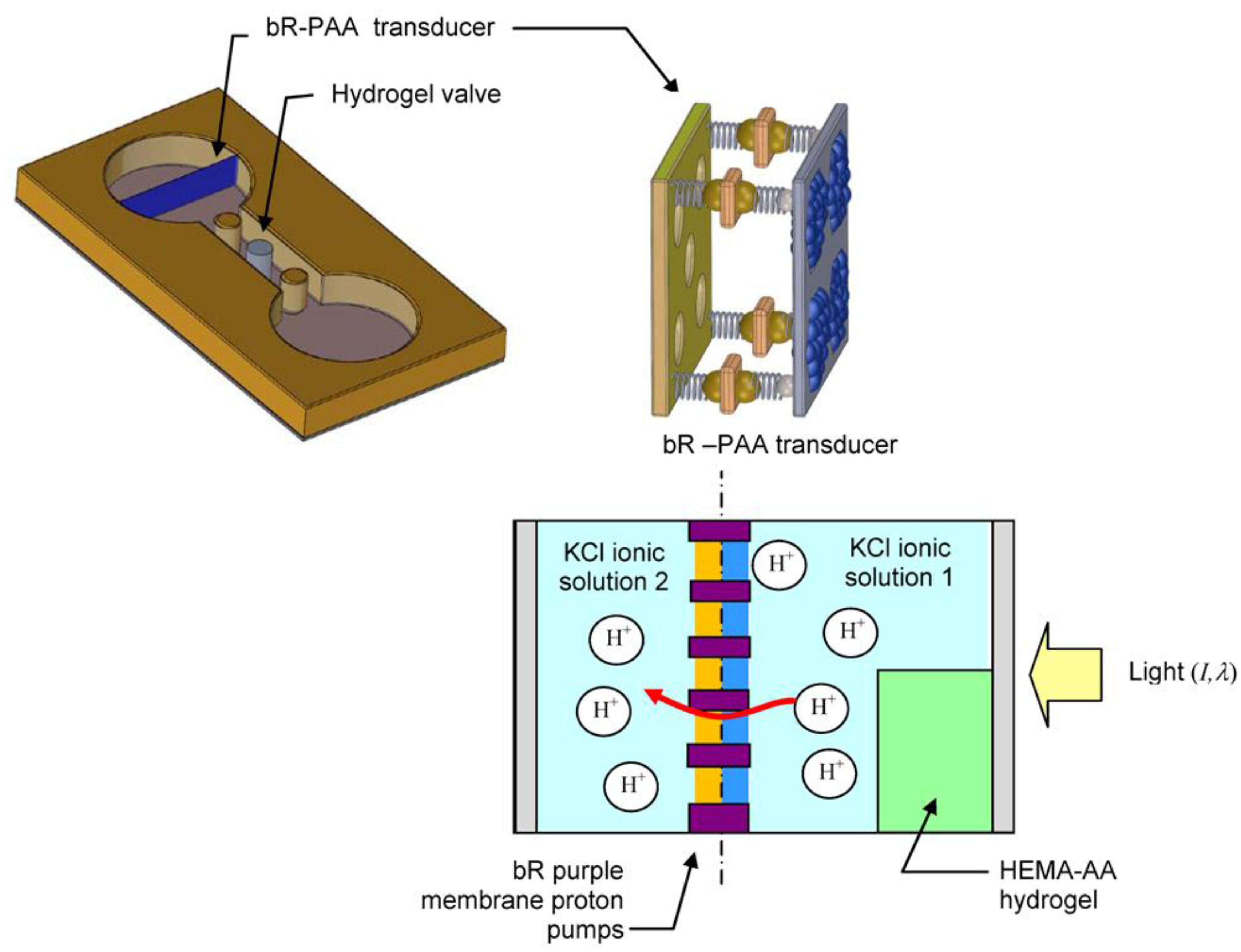
2. Light Driven Hydrogel Microactuator

The primary mechanism for generating a displacement, force or pressure is the expansion and contraction of the hydrogel actuator shell in response to the change in pH (ΔpH) of the surrounding solution. To externally control the volumetric transformation, a light responsive proton pump is used to generate a unidirectional flow of ions through the nano-porous membrane that increases or decreases the pH of the two separated ionic solutions. The key operating principles of the method of actuation (photoresponsive proton pumps) and actuating shell (ionic polymer gel) are described below.

2.1. Method of Actuation—Photoresponsive Proton Pumps

The ionic polymer gel microactuator is activated by an ultrathin biologically-based light transducer acting as a photon-powered proton pump. The organic material used to create the proton pumps is a light-harvesting protein found in the plasma membrane of Halobacterium salinarium [8,9,10]. In nature, the Archaea H. salinarium uses bacteriorhodopsin (bR) molecules as light sensitive carrier proteins to transport H+ ions from the cytoplasmic to the extracellular side through a transmembrane ion channel.
The purple membrane (PM) fragments, Figure 2a, are bR proteins comprised of linear pigment retinal bounded between seven amino helices arranged inside a lipid layer [9,10,11,12]. These PM patches are typically ~5 nm thick and have irregular shapes with a diameter of several hundred nanometers. An individual PM fragment will contain approximately 75% bacteriorhodopsin (bR) and 25% lipids [9]. The retinal protein is the functional molecule of the bR and gives the PM its dominant purple color. When exposed to sunlight the bR undergoes a photocycle process that transports H+ ions from the cytoplasm (interior) side of the cell membrane into the outer medium through transmembrane channels [9,12,13,14]. The PM is stable over prolonged periods of light exposure and preserves its photochemical characteristics under both dry and wet conditions. Figure 2b shows the measured optical absorbance characteristics of bR over the visible spectrum. The optical absorbance at a wavelength is the ratio of light intensity transmitted through the test sample and the original incident light intensity.
Figure 2. Bacteriorhodopsin (bR) membrane fragment and spectral absorbance in the visible light range. (a) SEM photograph of a bR purple membrane (PM) fragment (b) Measured optical absorbance of bR over the visible spectrum using a µQuant Microplate Spectrophotometer (from Bio-Tek Instruments).
Actuators 04 00237 g002
From the perspective of proton pump efficiency, it is critical that the spatially distributed PMs on the ultrathin photoelectric film are all oriented in the same direction when immobilized on the transducer surface [15,16]. Since the measured photoelectric signal is the collective response of many proton pumps acting simultaneously, the thin film fabrication technique must prevent a mixture of cytoplasmic and extracellular sides being adsorbed on the same electrode. In other words, efficient photon to ion flow and charge separation requires a common orientation PM patches on the electrode surface. Orientation specificity is necessary to control how the bR proton pumps are adsorbed onto the substrate. This can be achieved by applying number of different ways including the biotin labeling technique [17,18,19] used in this research. The biotinylation technique requires only one reactive residue that is located at the extracellular side of bR. Furthermore, it can be accessed at a specific pH making biotin labeling a highly repeatable and reproducible process at the molecular level.

2.2. Microactuator Shell—Ionic Polymer Hydrogel

An ionic polymer hydrogel, such as HEMA-AA, will undergo an abrupt volumetric change when the pH gradient creates an ion concentration difference between the inside and outside of the gel structure causing some H+ ions to move across the gel and thereby producing an osmotic pressure difference across the gel structure. If the osmotic pressure generated by ion movement into the gel exceeds the outside pressure, the internal forces will cause the tangled networks of crosslinked polymer chains to expand outward and the hydrogel to swell. If the networked hydrogel is immersed in a suitable ionic solution, then the polymer chains will absorb water and the association, dissociation and binding of the various ions to these chains will cause the hydrogel material to enlarge producing a usable micro-force.
Two important design considerations for developing pH-sensitive microactuator are the size of the hydrogel actuating shell and the ion concentration of the solution that surrounds the gel. The primary mechanism that influences the swelling response time of the gel structure is the diffusion of ions into the surrounding medium. In general, a relatively small hydrogel structure will react quicker to the ΔpH than a much larger mechanism [4,5,14,20] because the ion diffusion time in the gel network is dependent on the square of diffusion length [21]. Consequently, a fabricated hydrogel structure with a large surface-to-volume ratio will have more surface exposure to the activating solution and respond faster to ΔpH. The response time of the gels can be further increased by immersing the material in a buffered solution with a high concentration of H+ ions [20].

3. Microfabrication Processes

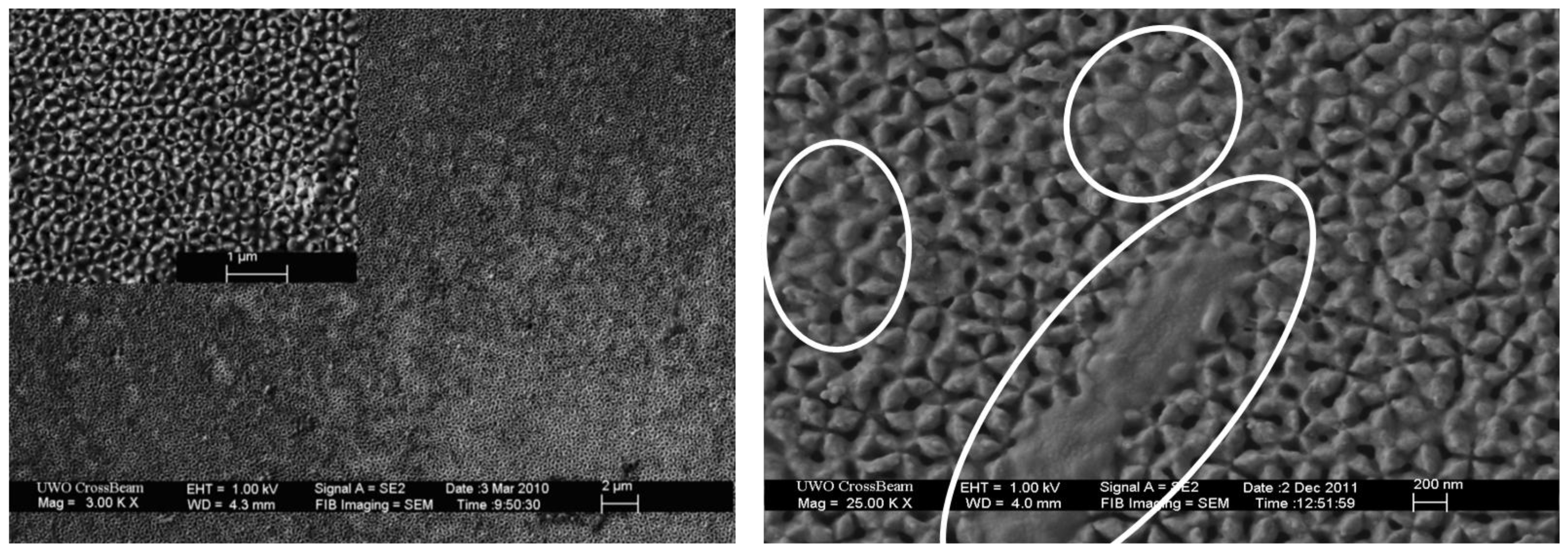
3.1. Light Driven bR-PAA Transducer

The mechanism for actuation is the light controlled transfer of protons across a very thin nano-porous substrate. The substrate must be sufficiently “stiff” to prevent the undesired deflection of the transducer under liquid or gel pressure, but not too thick to significantly impede the flow of ions. The substrate porosity (pore size and density) also impacts the rate in which the ions diffuse into and out-of the target solution. The pores must also be small enough not to allow the gel material to protrude, or ooze, into the ionic solution. To address these concerns, a 100 μm thick porous anodic alumina (PAA) substrate was used in this research. The selected PAA had a percent porosity of 20% and average pore diameter of 100 nm.
The self-assembly of the bR monolayer on the proton pump transducer’s surface requires first coating the PAA substrate with a thin layer of titanium (Ti) and then gold (Au). The role of the Ti is to create an adhesive layer that permanently connects the Au layer to the PAA substrate. The gold (Au) surface has a high affinity for thiol adsorption and forms a strong bond with the HS terminal of the thiols. For this experimental study the PAA substrate was first coated with a 3 nm Ti layer and then a 17 nm Au layer. Preliminary tests confirmed that the Au deposition method could produce coated surfaces as smooth as 0–4 nm maximum surface roughness. Once the nano-porous substrate is coated with an ultra-thin Au layer it can be bio-functionalized with biotinylated thiols. These thiols are used to adsorb the biotinylated bR on the transducer surface by mediating the sterptavidin proteins.
The process of assembling the bR monolayer starts with the biotin labeling technique first described by Henderson [17]. This procedure is essential to immobilize the bR purple membranes (PMs) on the porous substrate and ensure the efficiency of the proton pumps by orient the PM in a common direction. The biotin labeling procedure begins by adding 100 μL of 20 mg/mL biotin ester in dimethyl formamide to 2 mL of 1.9 mg/mL PMs suspended in 0.1 M sodium bicarbonate at pH 8.5. The solution is then mixed in an orbit shaker for 2 h at 20 °C, centrifuged and re-suspended in 0.1 M sodium bicarbonate at pH 8.5. This procedure is repeated three times and then the mixture rests for ~12 h to remove any biotin that remains weakly attached to the hydroxyl groups of the PMs. The resultant biotin-protein suspension is then further dialyzed against two changes of phosphate buffer saline (PBS) at pH 7.4 [18]. Finally, the bR proteins are suspended in PBS at a pH of 7.4.
The next step in the molecular self-assembly process is to incubate the Au coated substrate for 4 days at room temperature in a 4.5 × 10⁻⁴ M mixture of biotin terminated thiol and hydroxyl terminated thiol dissolved in ethanol. The mass ratio between the biotin-thiol and hydroxyl-thiol was 1:4. Upon completion the transducer substrate is washed with ethanol, milliQ water, and phosphate buffer saline (PBS) at pH 7.4. It is then further incubated at room temperature in 1 mL of 0.25 mg/mL streptavidin in PBS at a pH of 7.4 for 30 min. Finally, the prepared streptavidin covered substrate surface is washed thoroughly with PBS at a pH of 7.4 and incubated at room temperature in the biotinylated bR for 60 min [18].
Prior studies have shown that biotin labeling is highly effective and can produce a very thin bR PM layer that is <13 nm [16,22]. Figure 3 shows SEM photographs of the self-assembled ultra-thin bR films on the biofunctionalized PAA substrate at different magnifications. The encircled areas in the enlarged SEM image show the PM coated areas which partially cover porosity features on the PAA substrate. For these experiments the biotin ester (Biotin-XX) was purchased from Invitrogen (www.invitrogen.com), the biotinylated and hydroxyl-terminated thiols were acquired through nanoScience Instruments (www.nanoscience.com), and the streptavidin was obtained from Sigma-Aldrich.
Figure 3. SEM photographs of the self-assembled ultra-thin bR film on porous PAA substrate with increasing magnification. The enlarged area is shown in the upper left corner of the low magnification left photograph. Note that areas of significant PM coverage are encircled in white for the highly magnified image in the right photograph.
Actuators 04 00237 g003

3.2. pH Sensitive HEMA-AA Microactuator Shell

The hydrogel microactuator shell of the light driven device is created by chemically cross-linking the pH sensitive monomer acrylic acid (AA) to the neutral monomer 2-hydroxyethyl methacrylate (HEMA) with the cross linker ethylene glycol dimethacrylate. To prevent the pre-polymerization, the acrylic acid (AA) and HEMA is first purified by vacuum distillation at temperatures of less than 70 °C and 80 °C, respectively. The cross-linker ethylene glycol dimethacrylate is, however, used without undergoing additional purification. In this research the pH-sensitive hydrogel was created by carefully mixing the following materials (and mass quantities) to produce a homogeneously structured network: 2-hydroxyethyl methacrylate (0.5024 g), acrylic acid (0.095 g), ethylene glycol dimethacrylate (0.0195 g), and Irgacure 651 (0.013 g). The mixture is then poured into a cylindrical shaped PDMS mold with diameter of 75 μm and height of 100 μm. Polymerization of the actuator shell was achieved in 120 s using a 365 nm light source and Karl Suss MJB3 Mask Aligner at 12.5 mW/cm2.

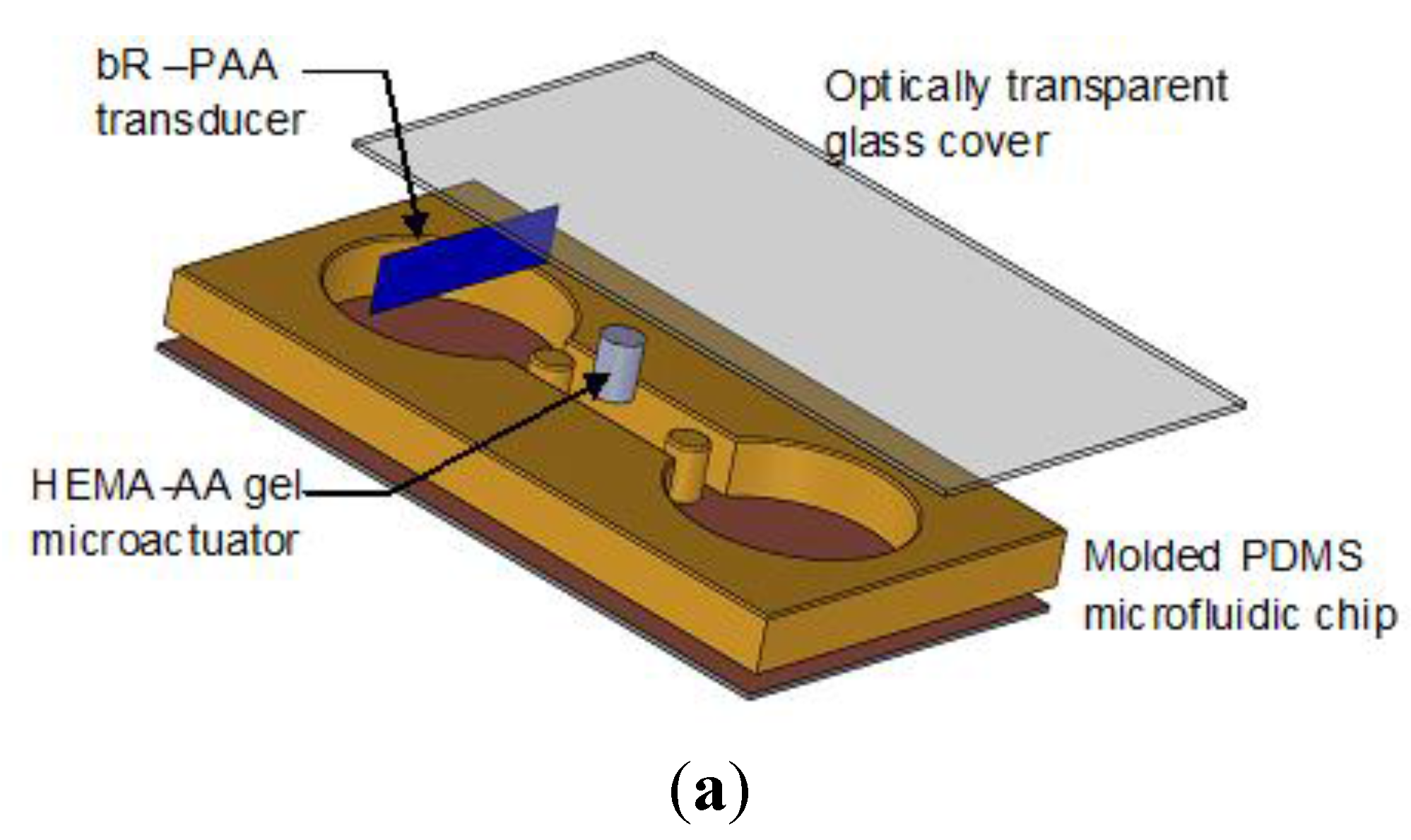
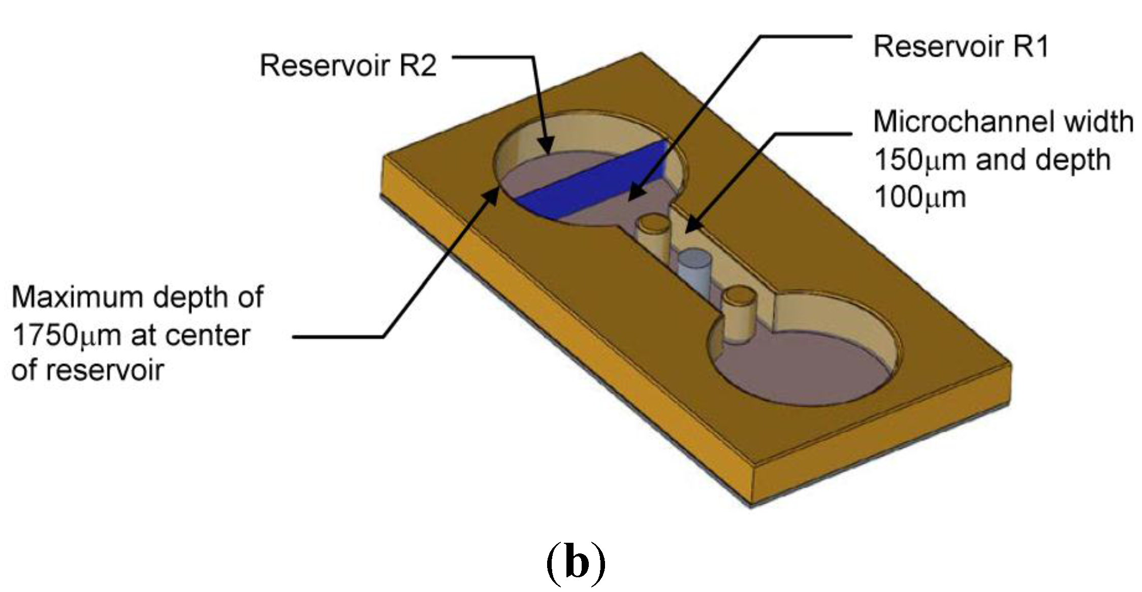
3.3. Polydimethylsiloxane (PDMS) Microfluidic Chip

The key steps in manufacturing the optically transparent polydimethylsiloxane (PDMS) microfluidic chip involve creating a photomask, spin coating SU-8 photoresist, polymerizing the SU-8 mold, and stamping the mold with PDMS to cast the final part in PDMS [1]. For this application, the SU-8 mold is fabricated by initially soaking a glass substrate in 20% HCl for two hours and then rinsing it with de-ionized water. The substrate is dried at 200 °C on a hot plate for 15 min and then cooled at room temperature in a clean room. Once cooled the coated substrate is coated with a 100 μm SU-8 3050 negative photoresist film by spinning it at 500 rpm for 5 s and then at 1000 rpm for 30 s. The photoresist film is further baked on a hotplate for 45 min at 95 °C. It is important that the heating and cooling stages of the photoresist fabrication process be performed gradually at 2–3 °C/min steps to avoid large temperature gradients across the film. These gradients will cause local stresses that affect the surface smoothness, and may generate cracks in the film and cause premature separation of the mold from the substrate.
The photoresist structure is then exposed to three doses of 365 nm light source (350 W Hg Arc lamp) for 12 s per dose. A 1 minute rest period exists between each dose to prevent overheating. After light treatment, the photoresist is baked once more for 1 min at 65 °C and 5 min at 95 °C. The photoresist is now placed in a SU-8 developing solution, gently rinsed with isopropanol for 10 s, and dried with compressed nitrogen. To avoid creating surface cracks, the resultant SU-8 micro mold is annealed by baking it at 200 °C on a hot plate for 20 min.
Finally, the PDMS replicated microfluidic chip used for experimental testing is produced from the SU-8 micromold using a PDMS casting process (Sylgard 184 kit from Dow Corning). The kit materials are appropriately mixed and de-gassed using a vacuum desiccator to ensure a homogenous mixture. To remove trapped air bubbles at the interface of the SU-8 mold and poured PDMS it is necessary to use a vacuum. Furthermore, the polymerization of the PDMS can be accelerated by incubating the material at 80 °C for 120 min. Once polymerized, the replicant PDMS chip is gently peeled off the mold in acetone to ensure that the microfeatures are not destroyed. The PDMS microfluidic device is then exposed to oxygen plasma for 15 s in STS Reactive Ion Etch System to make the chip’s surface hydrophilic. Although a variety of techniques have been described in the literature to make the PDMS surface hydrophilic [23], oxygen plasma was selected to ensure optical transparency. The fabricated hydrophilic PDMS chip can be stored in de-ionized water for up to 14 days [24].

3.4. Microfluidic Chip Assembly

The fabricated bR-PAA light activated transducer is inserted perpendicular to the flow channel in one of the major semi-spherical 3500 μm diameter reservoirs (Figure 4). The transducer forms a pH-controllable semi-porous barrier between the ionic solutions in the partitioned reservoirs R1 and R2. The assembly process involves mechanically stretching the flexible PDMS microfluidic device, inserting the bR-PAA transducer at the desired location, and then carefully releasing the polymer chip to tightly seal the edges. The mechanical seal eliminates any possible contamination that may arise from a chemical adhesive. The pH sensitive HEMA-AA gel microactuator is carefully inserted between two fixed posts molded in the microfluidic channel. Once the ionic KCl solution fills the reservoirs and microchannel, an optically transparent glass cover is placed on top of the device and sealed contamination and evaporation.
Figure 4. The components and assembly of the microfluidic chip used in this study. Note that the bR-PAA transducer is inserted perpendicular to the flow channel. (a) Individual components of the experimental PDMS microfluidic chip with two identical semi-spherical 3500 μm diameter reservoirs. (b) Assembled device and key dimensions. Note that the transducer divides one of the dominant reservoirs into two equal sections R1 and R2.
Actuators 04 00237 g004aActuators 04 00237 g004b

4. Experimental Results and Discussion

Experiments were performed to observe the functional behavior of the light-driven pH gradient transducer and the working mechanism of the hydrogel microactuator. The apparatus used to measure changes in the H+ ion concentration and pH of the activating solution is shown in Figure 5. However, prior to experimentation, several calibration tests were undertaken to examine the photo-electrochemical activity of the thiols adsorbed on Au-coated nano-porous PAA substrate and the streptavidin built on the thiols layer before depositing the light sensitive bR PMs. The preliminary tests showed that when exposed to visible light (18 mW, 568 nm), the thiols adsorbed on gold and the streptavidin built on the thiols layer produced no measurable photo-electrochemical activity. In other words, without the presence of bR PMs the transducer would not function as a proton pump. Any observed photoelectric and electrochemical behavior during the experiments will be the result of the photon responsive bR-PAA transducer.
Figure 5. Experimental apparatus used to measure the changes in pH of the ionic solution and observe swelling/deswelling of the hydrogel microactuator. A close-up view of the microchannel on the experimental PDMS microfluidic chip is shown on the right.
Actuators 04 00237 g005

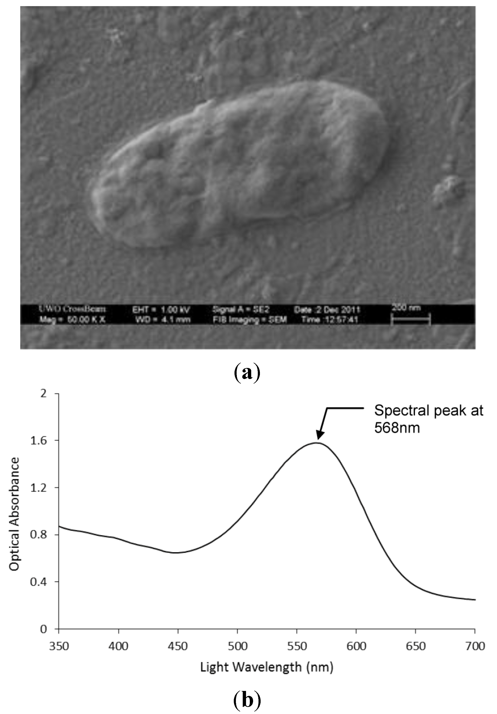
4.1. Photoelectric Analysis

A photocell was initially created by covering the dried bR film between its Au-PAA substrate and an optically transparent Indium Tin Oxide (ITO) contact glass plate to examine the photoelectric behavior of the proposed transducer. The gold and ITO surfaces act as microelectrodes that permit this simple sandwich structure to form a closed electronic circuit. The photocell was activated by an 18 mW, 568 nm light source because this wavelength corresponds to the peak photo-excitation of bR PMs. A nano-volt/micro-Ohm meter (Agilent 34420A) was used to record the voltage differences as shown in Figure 6. The photocell experiments demonstrated that the bR monolayer could generate nearly 1.33 mV/(mW·cm2) at this intensity and wavelength. It is important to note that no additional signal processing or amplification was performed during the experiment.
Figure 6. Measured response of a photocell constructed from the bR-PAA transducer when exposed to an 18 mW, 568 nm light source.
Actuators 04 00237 g006

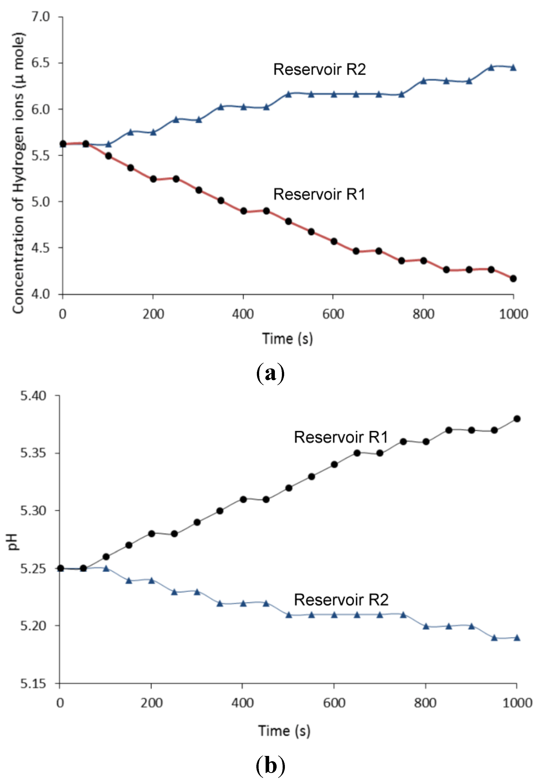
4.2. Light Driven pH Gradient Transducer

In the next set of experiments the reservoirs of the assembled microfluidic chip were filled with a 200 mM KCl solution. The electric potential dynamics of the ion solutions were measured using the nano-volt/micro-Ohm meter with platinum electrodes and the ΔpH of the liquids were recorded using a high-precision pH meter (Jenco Instruments 6230N). The pH meter enabled a sampling time of 1 s with a high degree of pH sensitivity of 0.01 pH units. To eliminate measurement distortions arising from electronic circuits no additional signal processing or amplification was performed. Furthermore, to minimize the effects of natural ionic diffusion across the nano-porous membrane, the liquid in the reservoirs (R1 and R2) on both sides of the transducer are initially equal and have the same ionic strength. All experiments in this study examined the unidirectional transport of H+ ions from the reservoir on the biofunctionalized side (R1) of the bR-PAA transducer to the second reservoir (R2). In addition, the bR-PAA transducer was investigated when the ionic solution’s pH was above 4.5 to avoid any potential interference that may occur at the isoelectric point of the bR proton pump. Unless stated otherwise, the pH measuring electrode was inserted in the microchannel at a distance of 250 μm from the transducer located in the first chamber or reservoir (R1) of the microfluidic chip.

4.2.1. Ion Transfer under Fixed Light Intensity

The first set of tests examined the electrochemical characteristics of the activating solution for a fixed light wavelength (568 nm) and intensity (18 mW). The light source was an 18 mW Melles Griot Argon Ion laser with a mechanical shutter and optical fiber angled at ~60° with the horizontal to deliver uniform illumination across the entire photosensitive surface of the bR-PAA transducer. Under dark conditions, the bR-PAA transducer showed no measurable changes. However, when the monochromatic light first illuminates the active transducer surface, the bR PM proton pumps start to transport H+ ions from the ionic solution at transducer’s interface to the ionic fluid in the opposite reservoir through the nano-porous membrane. The change in H+ ion concentration and pH of the liquids in reservoirs R1 and R2, arising from this transport process, is shown in Figure 7. Although the optically powered bR based opto-electrochemical transducer is relatively slow when compared to electrically driven pH gradient transducers, this transducer is able to transport ions between solutions without introducing additional electrical currents. As well, the system is remotely driven by a focused light beam that can originate from outside the enclosure or reservoir chamber.
Figure 7. The change in H+ ion concentration and pH over time of the two reservoirs separated by the bR-PAA transducer when exposed to a fixed 18 mW, 568 nm light source. (a) Change in H+ ion concentration over time. (b) The observed pH in the adjacent solutions over time.
Actuators 04 00237 g007

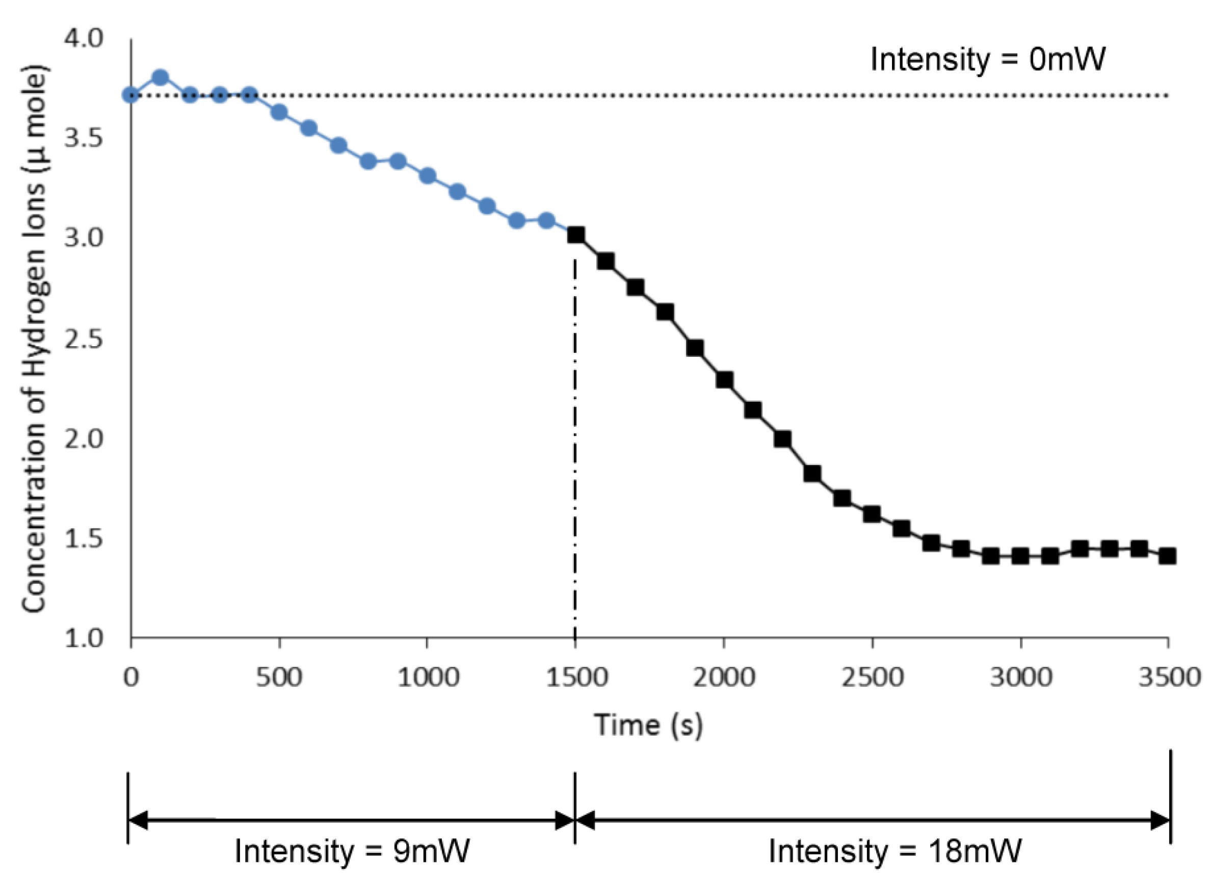
4.2.2. Ion Transfer under Variable Light Intensity

The change in H+ ion concentration is also a function of the light intensity as shown in Figure 8. Note that the dashed line at H+ concentration of 3.7 µmole shows no change in ion transfer when bR-PAA transducer is not exposed to light (i.e., 0 mW) for 3500 s. The blue line with circular symbols in Figure 8 is the change in H+ ion concentration over time (1500 s) when exposed to 9 mW light source. The black line with square symbols is shows the rapid increase in flow of ions as the intensity of the light is doubled to 18 mW from 1500 to 3500 s. Note that after 2500 s the concentration of H+ ions reached a steady state value around 1.5 µM due to the depletion of the hydrogen ions in the working solution. The active surface of the bR-PAA transducer is 0.2 cm. In general, the ion concentration is decreased producing an increase in the solution’s alkalinity. Simultaneously, these mechanisms increase the concentration of the hydrogen ions and, thereby, increase the acidity of the liquid in the opposite reservoir (R2).
Figure 8. The change in H+ ion concentration of the solution in reservoir R1 as a function of exposure to different levels of light intensity (0 mW, 9 mW, 18 mW).
Actuators 04 00237 g008
The measured pH changes in the solution are also a function of the light intensity as shown in Figure 9. These results indicate that a minimum level of light energy is necessary to activate the bR proton pumps and, thereby, alter the solution’s pH. Note that the nonlinear behavior is not unexpected as the observed pH change is the combined activity of the bR’s proton pumping action (which is inherently nonlinear) and the electrostatic interaction of ions transported across the bR-PAA transducer. The light-driven bR proton pumping action instantaneously depletes the concentration of the hydrogen ions at the interface of the bR surface with the ionic fluid. This depletion is compensated by diffusion of hydrogen ions from higher ion concentration regions in the same reservoir. However, the electrostatic repulsive forces between the mobile ions will randomly displace in the solution until the concentration is homogenized [25].
Figure 9. The change in steady-state pH of the solution in reservoir R1 as the intensity of light striking the bR-PAA transducer increases from 0 to 18 mW.
Actuators 04 00237 g009

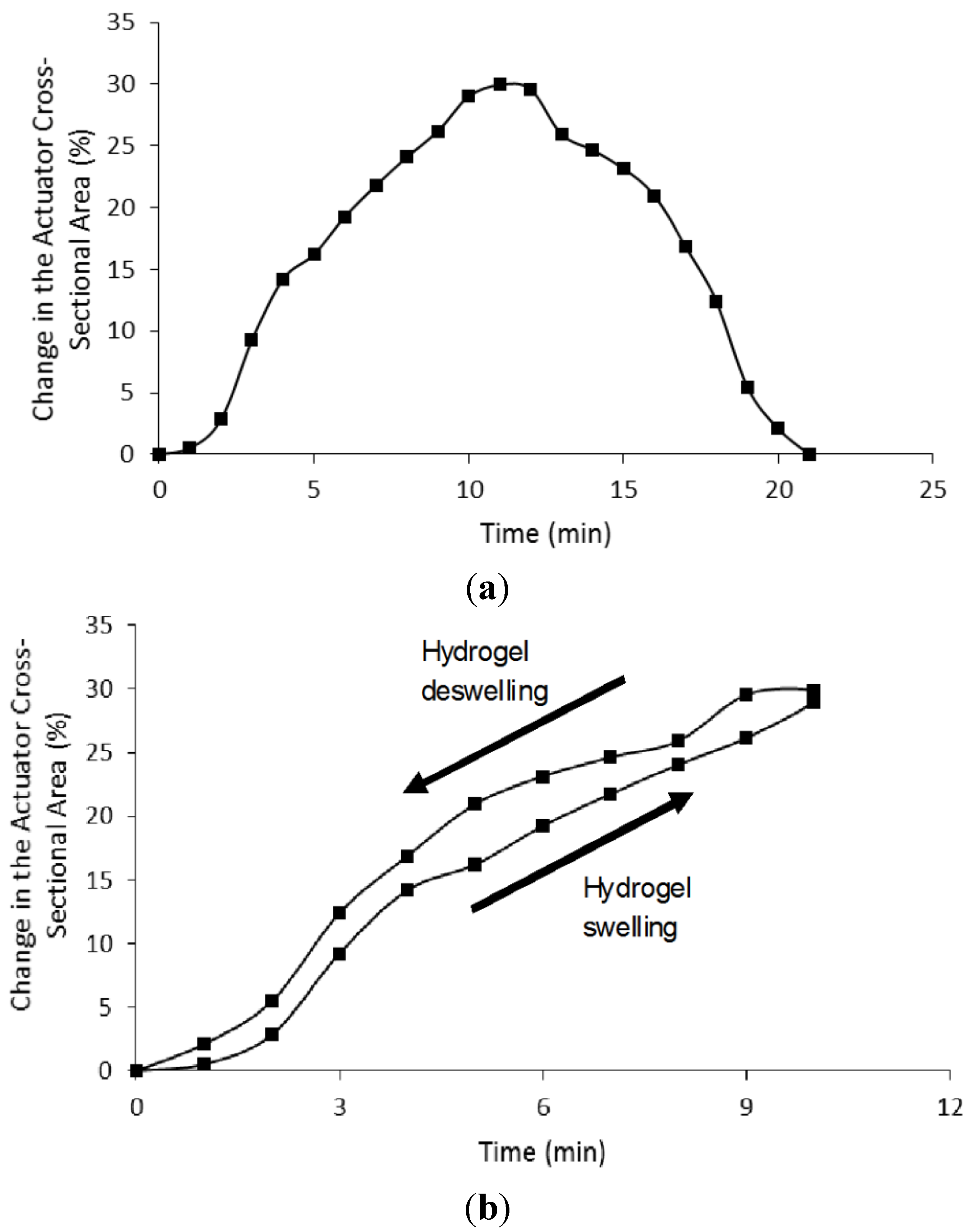
4.3. Microactuator Swelling Analysis

Microactuators are often very small material structures and mechanisms that perform mechanical work in response to external stimuli. The resulting mechanical action is able to generate tiny displacements or induce micro-forces on the surrounding medium [26]. In this regard, the swelling and de-swelling behavior of environmentally responsive hydrogels have been used as a valve actuator to control the flow of liquid along a variety of transport or mixing channels in LOC devices. The hydrogel micro-devices can be designed to both exhibit relatively large displacements and expand around structural obstacles. However, many of these gel actuating devices described in the literature are triggered using electrical or temperature control signals [27]. In contrast, the pH responsive hydrogel micro-actuators described in this paper can be driven by altering the ionic properties of the working fluid [28].
For simplicity the mechanical function of the hydrogel microactuator is to regulate fluid flow by acting as a valve that reduces the channel width when liquid pH exceeds a threshold value (Figure 10). The microactuator performance was evaluated by observing the geometrical changes to the HEMA-AA hydrogel actuator when the bR-PAA transducer is exposed to the monochromic light. The hydrogel actuator has a diameter of 75 μm and length of 100 μm. The chip was filled with an ionic solution of KCl with an ionic strength of 200 mM and at pH of 4.4. The pKa of the acrylic acid based hydrogel is 4.7 [29].
In this experiment the pH sensitive hydrogel was allowed to expand freely in the microchannel without any structural constraints. To prevent evaporation and contamination the experimental PDMS microfluidic chip was covered by 100 μm thick glass and sealed with an adhesive. The light source (18 mW, 568 nm) was delivered to the active photoresponsive side of the bR-PAA transducer using a flexible optical fiber. Physical changes to the volume, length and diameter of the hydrogel were observed within the first five minutes (Figure 11). The recorded measurements showed a volumetric change of more than 80% in less than 85 min. Similarly, an increase in length and diameter of 22% and 23%, respectively, was observed.
Figure 10. Photograph of the HEMA-AA gel actuator in the microchannel with an ionic solution that has a pH equivalent to reservoir R1.
Actuators 04 00237 g010
Figure 11. Measured dimensional changes to the HEMA-AA hydrogel actuator embedded in the microchannel as the bR-PAA transducer is exposed to a constant (18 mW, 568 nm) light source. (a) Percent change in gel volume over time. (b) Percent change in radial and axial displacements of gel over time.
Actuators 04 00237 g011
Figure 12. Changes in cross-sectional area and the observed hysteresis effect when H+ ions flow out of and then into the working solution. (a) Percentage change in hydrogel cross-sectional area over time when the flow of H+ ions is reversed at 10 minutes. Note that it takes at least two minutes after switching transducers for the hydrogel to respond and begin to contract. (b) Hysteresis effect exhibited by the hydrogel microactuator.
Actuators 04 00237 g012
The pH sensitive HEMA–AA hydrogel actuator was also examined for the swelling reversibility. In this set of experiments the direction of ion flow into the working solution was reversed by introducing a second bR-PAA transducer that acted as a second independent proton pumping station. The first bR-PAA transducer pumped H+ ions into the microchannel when activated by light, whilst the second bR-PAA pumped ions out of the same channel when triggered by the light signal. Note that both were not activated simultaneously. In this manner the expansion and contraction strokes of the microactuator material could be reversed by simply switching the light signal between these two opposite acting transducers. The percentage change in hydrogel cross-sectional area over time for swelling and then deswelling is shown in Figure 12a. The cross-sectional area was increased by 30% in the first 10 minutes of light exposure to bR-PAA transducer #1. At this time, the light was directed to the active surface of bR-PAA transducer #2 to increase the concentration of H+ ions in the working solution and, consequently, reduced the liquid pH. Once the switch in lighting had occurred the hydrogel would continue to expand for another minute and then remain constant for a further minute before beginning to deswell. However, the time response characteristics of the swelling/deswelling HEMA–AA hydrogel are comparable to the published results of other researchers [30,31]. This observation also implies that the ion transport processes into the polymer gel network is not instantaneous. The hysteresis behavior, Figure 12b, is not unexpected because the driving forces behind the hydrogel swelling stroke are the osmotic pressure and the repulsive forces between the charged polymer network responsive pendant groups, whereas the shrinking stroke is dependent mainly on the fluid flow out of the polymer network. Richter et al. [29] also observed a similar hysteresis phenomenon in pH responsive hydrogels.

5. Conclusions

The design, fabrication and experimental characterization of an ionic polymer microactuator driven by a photoresponsive transducer based on bacteriorhodopsin (bR) proton pumps have been described. The bR proton pumps are molecularly labeled, organized and adsorbed on Au-coated porous anodic alumina (PAA) substrate using a thiol-biotin-straptavidin molecular architecture technique. The self-assembled monolayer of bR proton pumps had a total thickness of 12.33 nm. When exposed to the monochromic light (18 mW, 568 nm), the proton pumps would transport hydrogen ions (H+) across the bR-PAA nano-porous membrane altering the pH of the working solution. The observed ΔpH was sufficient to trigger the swelling of a simple HEMA-AA gel microvalve inserted in a PDMS microfluidic device. Further experiments showed that it was also possible to reverse the swelling of the hydrogel by introducing a second bR-PAA transducer positioned to pump ions in the opposite direction. In other words, it was possible to create a hydrogel microactuator with forward and return strokes using the identical light driven bR-PAA transducers and light switching.

Acknowledgments

This work has been supported by the Natural Sciences and Engineering Research Council of Canada (NSERC). Portions of this research were carried out with the support of the staff in the Western Nanofabrication Facility at the University of Western Ontario.

Author Contributions

The authors contributed equally to the work.

Conflicts of Interest

The authors declare no conflict of interest.

References

  1. Abgrall, P.; Gué, A.-M. Lab-on-chip technologies: Making a microfluidic network and coupling it into a complete microsystem—A review. J. Micromech. Microeng. 2007, 17, R15–R49. [Google Scholar] [CrossRef]
  2. Watanabe, T.; Akiyama, M.; Totani, K.; Kuebler, S.M.; Stellacci, F.; Wenseleers, W.; Braun, K.; Marder, S.R.; Perry, J.W. Photoresonsive hydrogel microstructure fabricated by two-photon initiated polymerization. Adv. Funct. Mater. 2002, 12, 611–614. [Google Scholar] [CrossRef]
  3. Liu, R.H.; Yu, Q.; Beebe, D. Fabrication and characterization of hydrogel-based microvalves. J. Microelectron. Syst. 2002, 11, 45–53. [Google Scholar] [CrossRef]
  4. Baldi, A.; Gu, Y.; Loftness, P.E.; Siegel, R.A.; Ziaie, B. A hydrogel-actuated environmentally sensitive microvalve for active flow control. J. Microelectromech. Syst. 2003, 12, 613–621. [Google Scholar] [CrossRef] [Green Version]
  5. Al-Aribe, K.; Knopf, G.K.; Bassi, A.S. Photo-responsive hydrogel for controlling flow on a microfluidic chip. Proc. SPIE 2006, 6343. [Google Scholar] [CrossRef]
  6. Beebe, D.; Mensing, G.; Walker, G. Physics and Applications of Microfluidics in Biology Silicon based replication technology of 3D-microstuctures by conventional CD-injection molding techniques. In Proceedings of Transducers’97, Chicago, IL, USA, 16–19 June 2002; pp. 1415–1418.
  7. Yu, Q.; Bauer, J.M.; Moore, J.S.; Beebe, D.J. Responsive biomimetic hydrogel valve for microfluidics. Appl. Phys. Lett. 2001, 78, 2589–2591. [Google Scholar] [CrossRef]
  8. Oesterhelt, D.; Stoeckenius, W. Rhodopsin-like protein from the purple membrane of Halbacterium. Nature 1971, 233, 149–152. [Google Scholar]
  9. Hampp, N. Bacteriorhodopsin as a photochromic retinal protein for optical memories. Chem. Rev. 2000, 100, 1755–1776. [Google Scholar] [CrossRef] [PubMed]
  10. Wang, W.W.; Knopf, G.K.; Bassi, A. Photoelectric properties of a detector based on dried bacteriorhodopsin film. Biosens. Bioelectron. 2005, 21, 1309–1319. [Google Scholar] [CrossRef] [PubMed]
  11. Varo, G.; Lanyi, J. Thermodynamics and energy coupling in the bacteriorhodopsin photocycle. Biochemistry 1991, 30, 5016–5022. [Google Scholar] [CrossRef] [PubMed]
  12. Kuhlbrandt, W. Bacteriorhodopsin—the movie. Nature 2000, 406, 569–570. [Google Scholar] [CrossRef] [PubMed]
  13. Eroglu, I.; Aydemir, A.; Turker, L.; Yucel, M. Photoresponse of bacteriorhodopsion immobilized in polyacrylamide gel membranes. J. Membr. Sci. 1994, 86, 171–179. [Google Scholar] [CrossRef]
  14. Liu, S.Y.; Kono, M.; Ebrey, T.G. Effect of pH buffer molecules on the light-induced currents from oriented purple membrane. Biophys. J. 1991, 60, 204–216. [Google Scholar] [CrossRef]
  15. Schranz, M.; Noll, F.; Hampp, N. Oriented purple membrane monolayers covalently attached to gold by multiple thiole linkages analyzed by single molecule force spectroscopy. Langmuir 2007, 23, 11134–11138. [Google Scholar] [CrossRef] [PubMed]
  16. Al-Aribe, K.; Knopf, G.K.; Bassi, A.S. Photoelectric monolayers based on self-assembled and oriented purple membrane patches. J. Microelectron. Syst. 2011, 20, 800–810. [Google Scholar] [CrossRef]
  17. Henderson, R.; Stubb, J.; Whytock, S. Specific labelling of the protein and lipid on the extracellular surface of purple membrane. J. Mol. Biol. 1978, 123, 259–274. [Google Scholar] [CrossRef]
  18. Chen, D.; Lu, Y.; Sui, S.; Xu, B.; Hu, K. Oriented assembly of purple membrane on solid support mediated by molecular recognition. J. Phys. Chem. B 2003, 107, 3598–3605. [Google Scholar] [CrossRef]
  19. Ren, Q.; Zhao, Y.; Han, L.; Zhao, H. A nanomechanical device based on light-driven proton pumps. Nanotechnology 2006, 17, 1778–1785. [Google Scholar] [CrossRef]
  20. Chiu, Y.; Varanasi, P.P.; McGlade, M.J.; Varanasi, S. pH-induced swelling kinetics of polelectrolyte hydrogels. J. Appl. Polymer Sci. 1995, 58, 2161–2176. [Google Scholar] [CrossRef]
  21. Lin, C.-C.; Metters, A.T. Hydrogels in controlled release formulations: Network design and mathematical modeling. Adv. Drug Deliv. Rev. 2006, 58, 1379–1408. [Google Scholar] [CrossRef] [PubMed]
  22. Al-Aribe, K.; Knopf, G.K.; Bassi, A.S. Fabrication of an optically driven pH-gradient generator based on self-assembled proton pumps. Microfluid. Nanofluid. 2012, 12, 325–335. [Google Scholar] [CrossRef]
  23. Feng, J.-T.; Zhao, Y.-P. Influence of different amount of Au on the wetting behavior of PDMS membrane. Biomed. Microdevices 2008, 10, 65–72. [Google Scholar] [CrossRef] [PubMed]
  24. Kim, B.; Peterson, E.T.K.; Papautsky, I. Long-term stability of plasma oxidized PDMS Surfaces. In Proceedings of IEEE EMBS, San Francisco, CA, USA, 1–4 September 2004; pp. 5013–5016.
  25. Horn, C.; Steinem, C. Photocurrents generated by bacteriorhodopsin adsorbed on nano-black lipid membranes. Biophys. J. 2005, 89, 1046–1054. [Google Scholar] [CrossRef] [PubMed]
  26. Tabib-Azar, M. Microactuators; Electrical, Magnetic, Thermal, Optical, Mechanical, Chemical and Smart Structures, 1st ed.; Kluwer Academic Publishers: New York, NY, USA, 1998; pp. 219–274. [Google Scholar]
  27. Richter, A.; Kuckling, D.; Howitz, S.; Gehring, T.; Arndt, K. Electronically controllable microvalves based on smart hydrogels: Magnitudes and potential applications. J. Microelectromech. Syst. 2003, 12, 748–753. [Google Scholar] [CrossRef]
  28. Dong, L.; Agarwal, A.K.; Beebe, D.J.; Jiang, H. Adaptive liquid microlenses activated by stimuli-responsive hydrogels. Nature 2006, 442, 551–554. [Google Scholar] [CrossRef] [PubMed]
  29. Richter, A.; Paschew, G.; Klatt, S.; Lienig, J.; Arndt, K.; Hans-Jürgen, P.; Adler, H.P. Review on hydrogel-based pH sensors and microsensors. Sensors 2008, 8, 561–581. [Google Scholar] [CrossRef]
  30. Jang, J.; Jhaveri, S.J.; Rasin, B.; Koh, C.Y.; Ober, C.K.; Thomas, E.L. Three dimensionally-patterned submicrometer-scale hydrogel/air networks that offer a new platform for biomedical applications. Nano Lett. 2008, 8, 1456–1460. [Google Scholar] [CrossRef] [PubMed]
  31. Peppas, N.A.; Hilt, J.Z.; Khademhosseini, A.; Langer, R. Hydrogels in biology and medicine: From molecular principles to bionanotechnology. Adv. Mater. 2006, 18, 1345–1360. [Google Scholar] [CrossRef]

