1. Introduction
Recently, with the development of nanotechnology, manipulation under an observation instrument at a high resolution is becoming increasingly important for researching nanomaterials, such as their fabrication, evaluation, and modification. As technologies evolve, use of the scanning electron microscope (SEM) has become popular, whereby a corresponding positioning technique is required. Compared to the traditional optical microscope, SEM can provide a much higher resolution and a better working environment. However, the space of the SEM chamber is usually so confined that the size of the positioner that can be used is severely limited.
For positioner motions spanning a wide range of excursions, a coarse motion approach and a fine motion approach are necessary. Generally, the two functions are achieved using separate mechanisms, which usually results in a large size for the positioner. A number of efforts have been expended for improving this design feature so that one mechanism could combine coarse and fine motions. A synopsis of these efforts can be found in the literature, including the Inchworm [
1,
2,
3,
4], Impact Drive [
5], and Beetle types [
6,
7]. Recently, a new type of positioner, called the Koala Drive [
8] has been reported. The new operating principle provides a smooth travel sequence, compact size, and a simple construction for its potential application in the scanning probe microscope (STM). The use of the Koala Drive makes the STM design ultracompact and leads accordingly to a high mechanical stability. However, the reported Koala Drive only gives one degree of freedom to the positioner. One would expect a compact positioner with more degrees of freedom for wider applications.
In the present paper, a new ultracompact planar positioner with two degrees of freedom, which is driven by unbalanced frictional forces, is proposed. The working principle is illustrated, and the performance of the prototype is evaluated in atmosphere and in vacuum. Furthermore, we propose additional improvements for the performance of the positioner.
2. Working Principle
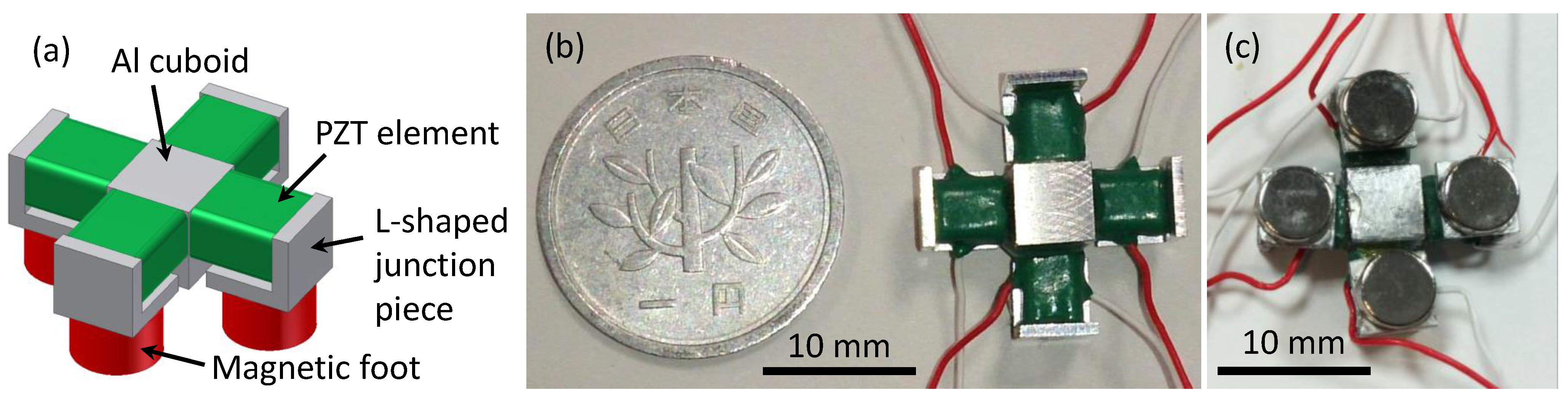
Figure 1a represents the schematic diagram of the designed positioner. Four identical lead zirconate titanate (PZT) multilayer piezoelectric elements (AE0203D04F, NEC TOKIN Corporation), with a 3.5 mm × 4.5 mm × 5 mm in size, and a maximum displacement of 4.6 ± 1.5 μm at a maximum driving voltage of 150 V, were symmetrically joined to an aluminum (Al) cuboid. Correspondingly, four neodymium magnetic feet (5 mm in diameter and 3 mm in thickness, with a magnetic flux density of 374 mT) were fixed to the four PZT piezoelectric elements using L-shaped Al junction pieces, respectively. All of the components were glued using an epoxy bonding agent.
Figure 1b,c show the prototype of the designed positioner with a size of 17 mm × 17 mm × 9 mm. The positioner with such a compact size has potential applications to the microscopes that require significant reductions of the size of the positioner.
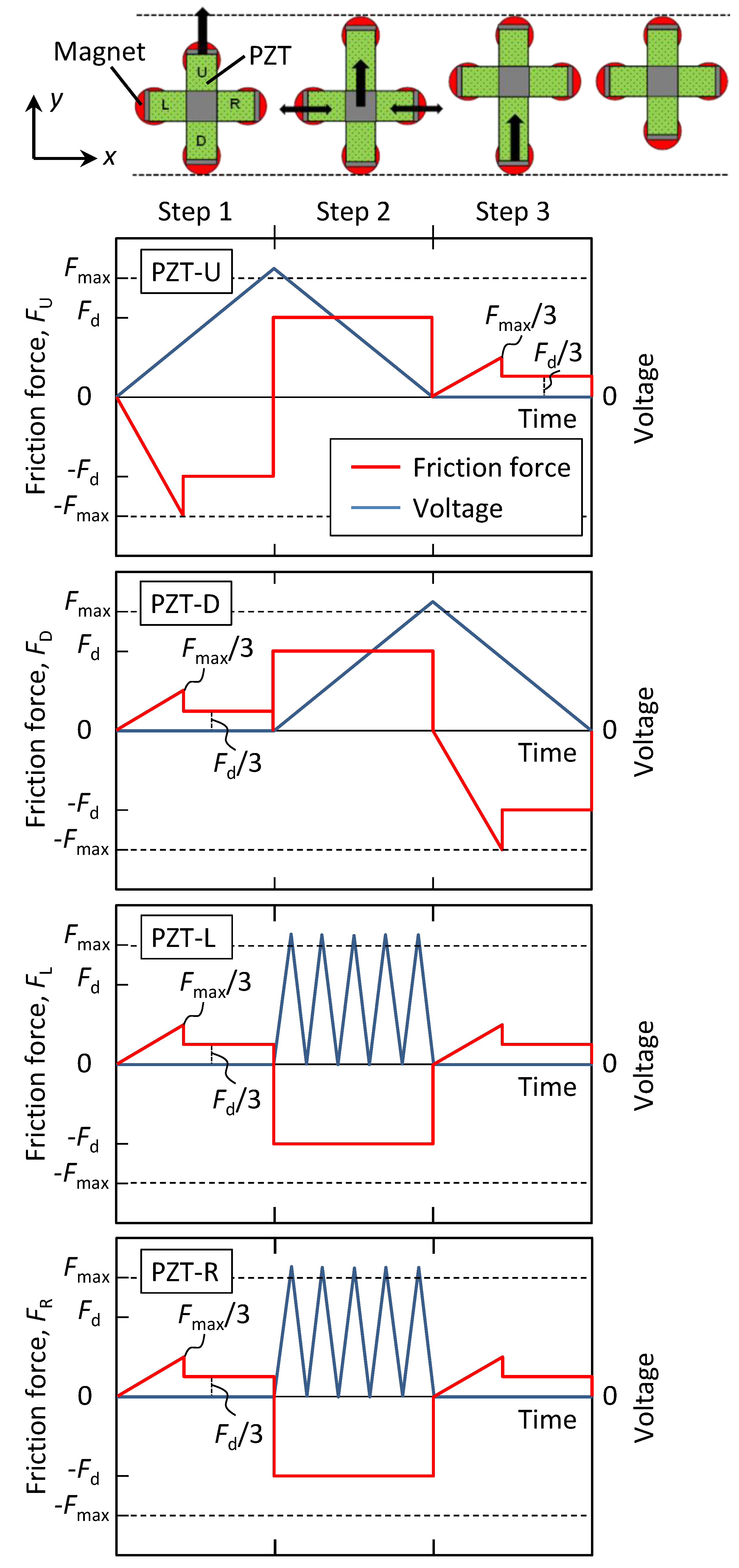
For controlling the motion of the positioner, alternating static and kinetic frictional forces were utilized. Considering one cycle of motion along the
y direction as an example, the voltage patterns applied to the PZT elements and the respective frictional force on the magnetic foot,
F, are illustrated in
Figure 2. Here, the four PZT piezoelectric elements are defined as PZT-up (U), -down (D), -left (L) and -right (R), and the corresponding magnetic feet are defined as magnet-U, -D, -L and -R, respectively, as indicated in
Figure 2. In addition, the maximum static frictional force is defined as
Fmax, the kinetic frictional force as
Fd, and the frictional force along the
y direction as positive.
Figure 1.
(a) Schematic diagram of the designed positioner. (b) Top view of the prototype of the designed positioner compared with a coin. (c) Bottom view of the prototype of the designed positioner.
Figure 1.
(a) Schematic diagram of the designed positioner. (b) Top view of the prototype of the designed positioner compared with a coin. (c) Bottom view of the prototype of the designed positioner.
In Step 1, a voltage is applied to PZT-U only, and PZT-U tends to elongate by overcoming the static frictional forces generated by the magnetic feet. With the increase of the applied voltage, the static frictional force on magnet-U increases more rapidly than those on magnets-D, -L and -R, which equally share the former. At a certain voltage, magnet-U, first, reaches −
Fmax, and PZT-U thus starts to elongate upwards and goes into sliding friction. During Step 1, the respective frictional force on the magnetic foot is expressed by Equation (1) as
where the subscripts U, D, L, and R, stand for magnets-U, -D, -L, and -R, and 1 and 2 (discussed below) stand for Steps 1 and 2, respectively. Note that during Step 1, the frictional forces on magnets-D, -L and -R do not reach
Fmax, and hence PZTs-D, -L, and -R are kept still together with the central Al cuboid due to the restriction of the static frictional forces.
In Step 2, PZT-U contracts and PZT-D elongates upwards simultaneously, under respective decreasing and increasing voltages. Meanwhile, PZTs-L and -R oscillate under a continuous sinusoidal voltage wave, and the prestatic frictional forces on magnets-L and -R change into kinetic frictional forces under the oscillation. With this contribution, PZTs-L and -R move upwards together with PZTs-U and -D, as well as the Al cuboid. On the other hand, magnets-U and -D share the kinetic frictional forces on magnets-L and -R, as expressed by Equation (2) as
Note that during Step 2, although the frictional forces on magnets-U and -D attain a force value equal to Fd, they have not reached Fmax; hence, magnets-U and -D are kept still, and just PZT-U contracts and PZT-D elongates, respectively. It should be mentioned that the oscillation of PZTs-L and -R constitutes the most important proposal of the present research. With the static frictional force changing into a kinetic frictional force, the prebalanced forces become unbalanced, and hence the positioner can be driven to motion.
Finally, in Step 3, similar to that of Step 1, only PZT-D contracts under a decreasing voltage, while the other contacts are kept still and without any voltage applied to them. Utilizing the working principle described above, the positioner can achieve a planar motion to an arbitrary position by combining continuous motions along the x and y directions.
Figure 2.
Illustrations of the working principle of the positioner, the voltage patterns applied to the PZT elements and the corresponding frictional forces on the magnetic feet during one cycle of motion.
Figure 2.
Illustrations of the working principle of the positioner, the voltage patterns applied to the PZT elements and the corresponding frictional forces on the magnetic feet during one cycle of motion.
3. Performance Evaluation
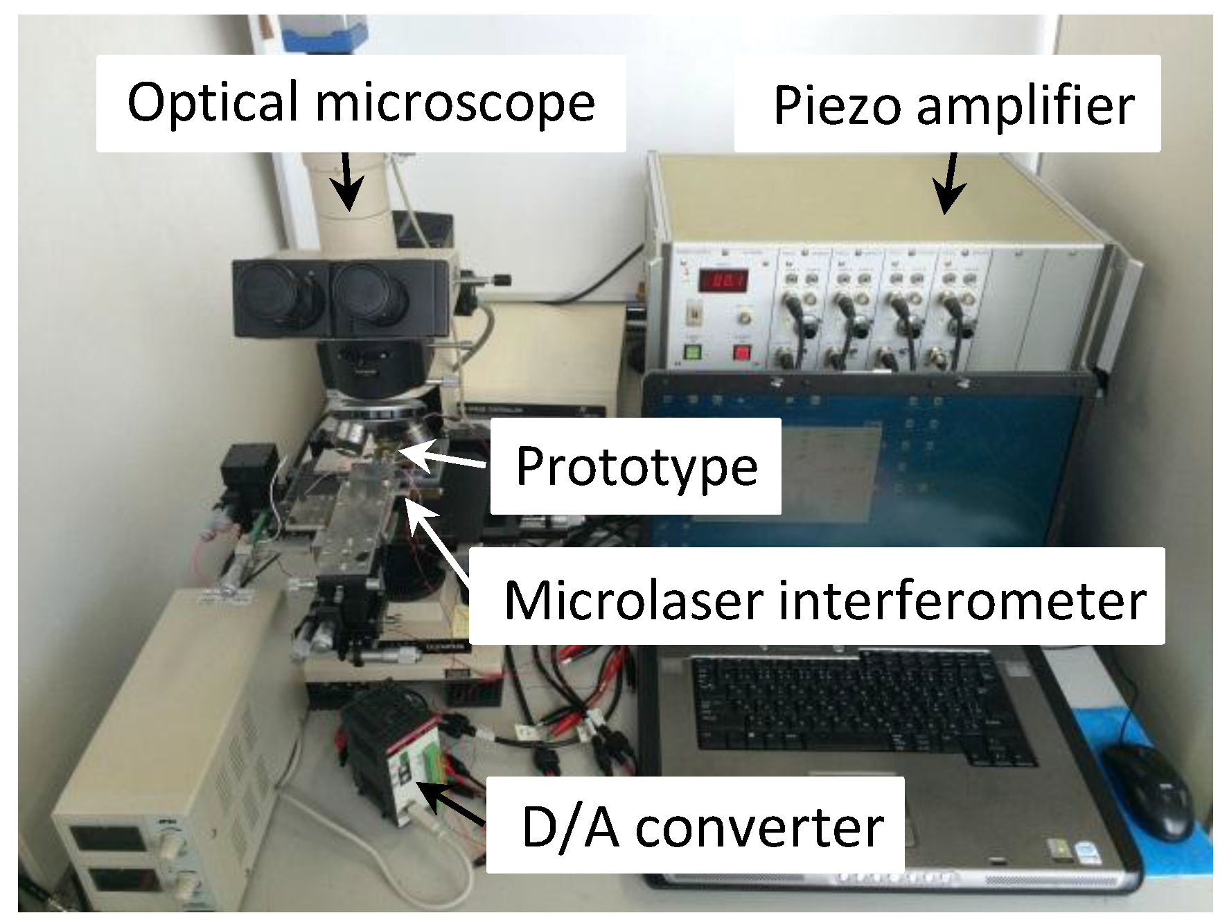
The positioner was operated by a control program created using Visual Basic 6.0. A computer was connected with a D/A converter (DAI12-4 (USB) GY, Contec Co. Ltd., Osaka, Japan), with an output range of 0–10 V, a resolution of 12 bits, and four channels, which plays a role in converting the digital signal from the computer into an analog signal. The analog signals from the D/A converter were then amplified using a piezo amplifier (M-2629B, MESS-TEK Co. Ltd., Saitama, Japan), and the corresponding voltages were output to the PZT elements. The experiment system is shown in
Figure 3.
Figure 3.
The experiment system.
Figure 3.
The experiment system.
For evaluating the performance of the positioner, the motions were conducted on the ferritic stainless plate SUS430 (abbreviated as the “stainless plate”) with a surface roughness of Ra = 0.116 μm. Herein, the stainless plate was used to enhance the frictional forces on the magnetic feet. The applied voltages were increased or decreased by 0.05 V and the maximum voltage applied to PZTs-U and -D was 138 V. The optimum operating conditions were determined by investigating the effects of the oscillation amplitude (A) and the oscillation frequency (f) on the motion of the positioner, both of which affected the oscillations of PZTs-L and -R in Step 2. Under each set of testing conditions, five cycles of motion were conducted three times, and the average travel distance over one cycle (abbreviated as the “step size”) was calculated by dividing the average total travel distance by five. The total travel distance for the five cycles was measured using dedicated software measurements on a magnified view of the motion of the positioner. These experiments were conducted under an optical microscope under atmospheric conditions. Finally, based on the determined optimum values of A and f, the positioner was tested under atmospheric and vacuum conditions for comparison.
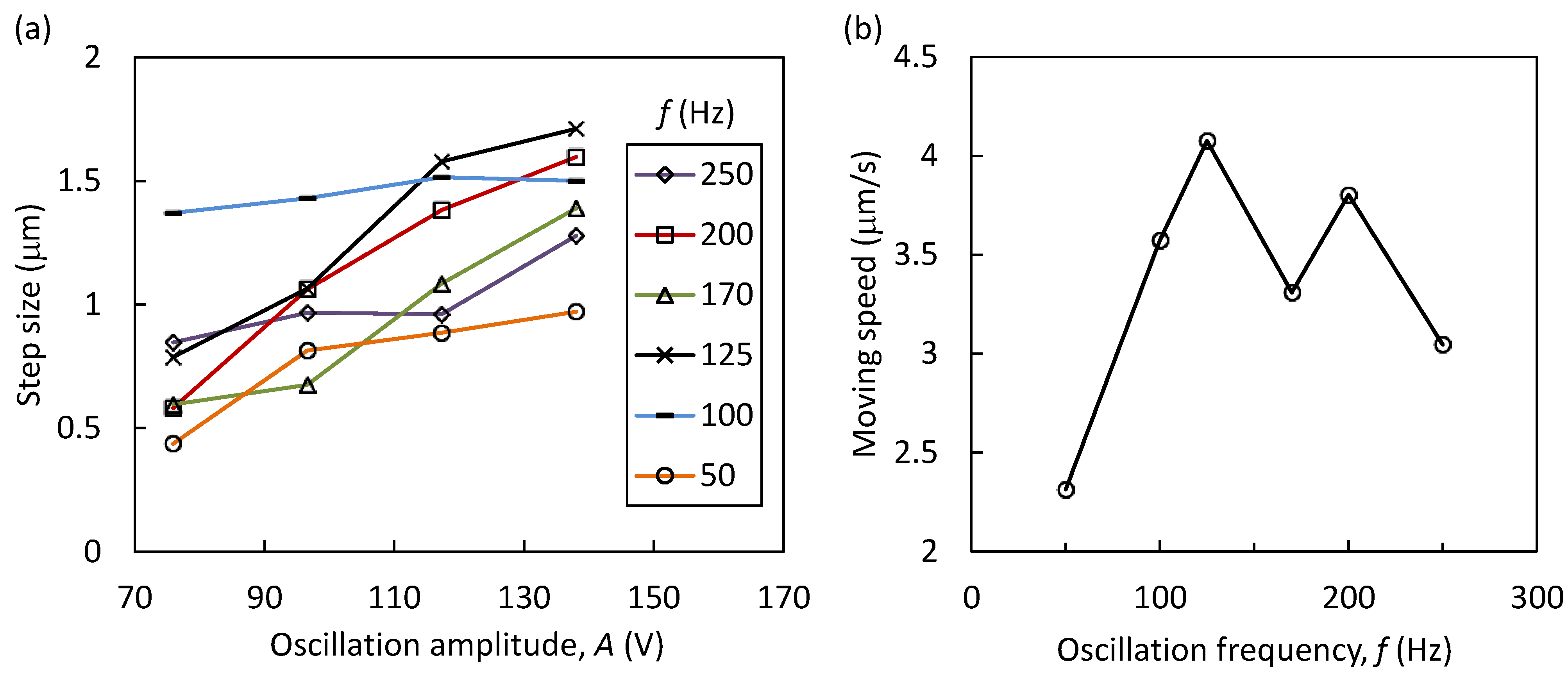
The step size variation as a function of
A (75–138 V) at different values of
f (50–250 Hz) is shown in
Figure 4a. According to the result, the step size under a constant
f monotonically increased with increases in
A, and it reached a maximum step size value at 138 V at an
f value of 125 Hz. The decrease of the step size at
f values above 125 Hz may be due to the fact that the PZT piezoelectric elements or the piezo amplifier could not respond well to a high-oscillation frequency and, hence, inadequate oscillation frequencies were elicited. In addition,
Figure 4b represents the variation of the moving speed
versus the oscillation frequency at an
A value of 138 V, under which it took a period of approximately 400 ms for one cycle. According to these results, the optimum values of
A and
f were determined to be 138 V and 125 Hz, respectively.
Figure 4.
(a) The variation of the step size versus the oscillation amplitude at various oscillation frequencies. (b) The variation of the moving speed versus the oscillation frequency at an A value of 138 V.
Figure 4.
(a) The variation of the step size versus the oscillation amplitude at various oscillation frequencies. (b) The variation of the moving speed versus the oscillation frequency at an A value of 138 V.
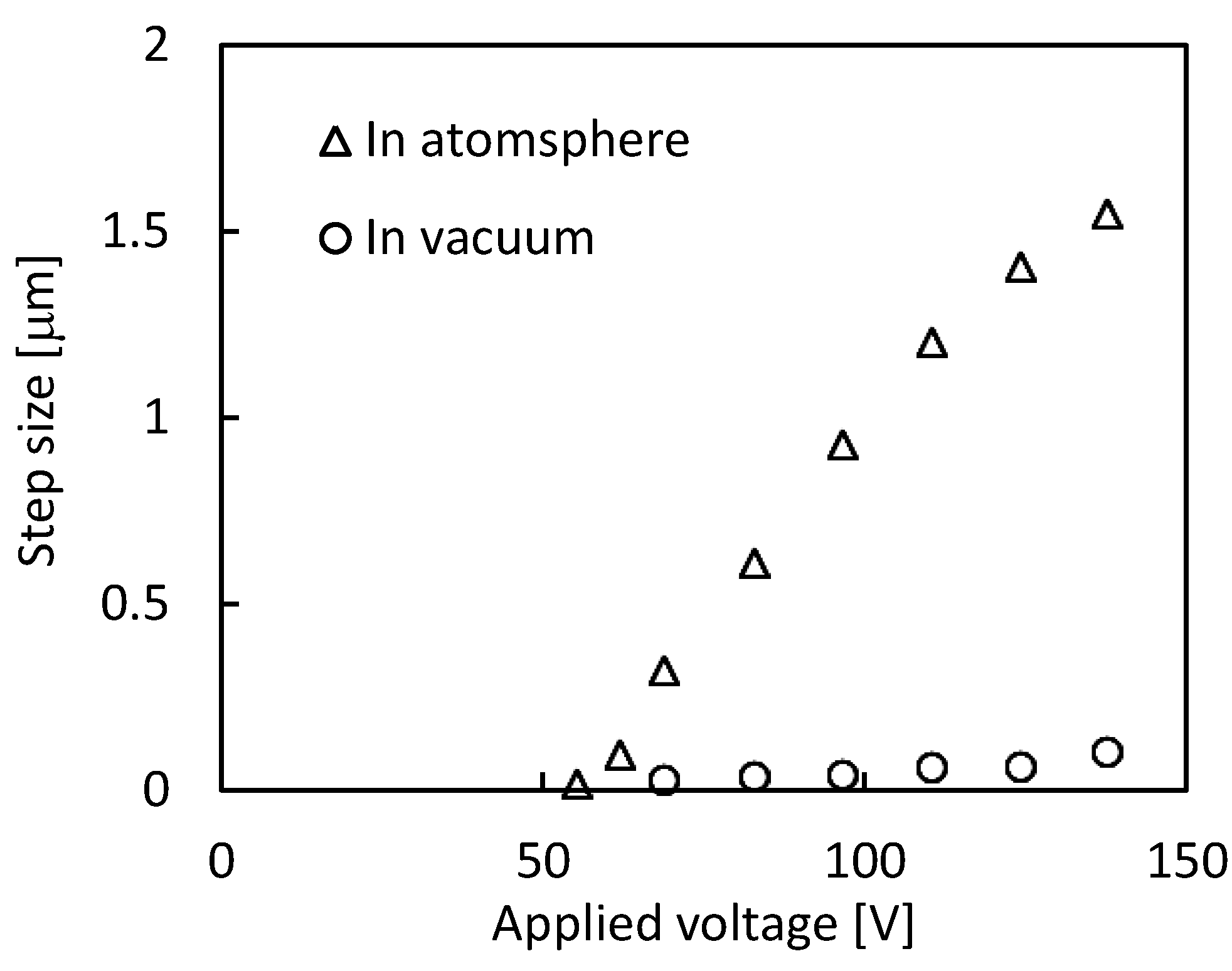
Based on the investigated optimum operating conditions, the motions of the positioner under atmospheric and vacuum conditions were respectively tested at different voltages within a voltage range of 0–138 V that were applied to PZTs-U and -D. The experiments in vacuum were conducted in the SEM chamber (JSM-6510, JEOL Co., Ltd., Tokyo, Japan) under a pressure of 10 Pa. Similar to the experiment described above, five cycles of motion were conducted three times under each set of testing conditions, and the step size was then calculated.
The results are represented in
Figure 5. Under atmospheric conditions, there was a threshold voltage of approximately 50 V, under which the positioner did not operate. When the voltage applied to PZTs-U and -D was above this threshold voltage, the step size monotonically increased at increasing voltages. Herein, we measured a minimum step size of approximately 17 nm at 55 V, under atmospheric conditions. In contrast, the positioner could achieve a maximum moving speed that was approximately 4 μm/s at 138 V, under which the step size was approximately 1.6 μm over a period of 400 ms for one cycle. It should be mentioned that the moving speed may be dependent on the performance of the control program that determines the voltage application, especially for the frequency of the sinusoidal voltage wave. On the other hand, the variation of the step size in vacuum was similar to that in the atmosphere. Nevertheless, the step size in vacuum significantly decreased to values in the submicrometer range. This may have been due to the fact that the vacuum environment desorbed the surface adsorbates from the stainless plate and the magnetic feet, such as the water molecules, oxygen, and others, and the friction coefficient between the magnetic foot and the plate significantly increased [
9,
10,
11]. With the increased friction coefficient, the frictional forces on the magnetic feet increased and resulted in a significant decrease of the step size in vacuum.
According to the analysis above, the performance of the positioner was significantly dependent on the frictional forces on the magnetic feet. We can control the step size by adjusting the frictional force through the variation of the materials of the magnetic foot, substrate, and those of the operational environment.
Figure 5.
The variation of step size versus the applied voltage to PZTs-U and -D under atmospheric and vacuum conditions.
Figure 5.
The variation of step size versus the applied voltage to PZTs-U and -D under atmospheric and vacuum conditions.

