1. Introduction
Electromechanical contactors are widely used switching devices designed to control the flow of electrical power in a variety of industrial, commercial and transportation applications [
1]. They are particularly well known and extensively optimised for alternating current (AC) systems, where zero-crossing of the current naturally assists arc extinction and reduces contact wear. In fact, recent AC contactors have reached a very high level of technological maturity, with standardised designs, predictable lifetimes, and well-established performance characteristics. Their widespread adoption in motor control, power distribution, and automation systems has made them a cornerstone component in modern electrical engineering [
2].
However, when it comes to DC operations, especially at extremely high currents, there is a much more limited availability of literature and market-ready products. Unlike AC systems, DC contact interruption does not benefit from natural current zero-crossings, making arc extinction more difficult and increasing thermal and mechanical stress on the contacts [
3]. Commercially available high-current contactors are often limited by contact erosion, overheating, electromagnetic blow-off forces, and overall device size and cost. Consequently, achieving reliable switching at very high currents, especially in compact and weight-constrained systems, remains a significant design challenge.
In most applications for fast and precise switching, a solid-state device is used. They utilise an electronic semiconductor device such as a thyristor, transistor or MOSFET [
4]. The advantage of using a semiconductor over an electromechanical contactor is that they are much faster at switching. However, their disadvantages are their on-state voltage drop, which results in heat dissipation, and the short circuit condition they cause if they fail. This short circuit condition is dangerous; therefore, generally, for higher current applications, electromechanical contactors are implemented [
5]. Furthermore, when MOSFETs are used to conduct high currents, multiple devices are connected in parallel. This approach increases the overall current-handling capability by distributing the load current across several MOSFETs, thus reducing the electrical and thermal stress on each individual device. This paralleling of MOSFETs lowers the effective on-state resistance of each switching device, which reduces the voltage drop and conduction losses, thus improving the overall thermal performance [
6]. The drawback of this configuration is that the larger the number of parallel devices, the larger the probability that one can fail, hence creating a dangerous short circuit risk. Electromechanical contactors, on the other hand, are switching devices which must be energised through an electromagnetic circuit to turn on. Therefore, they offer greater safety and reliability than MOSFETs since their tendency of failing in a short circuit position is almost null.
A particular transport application where extremely high current capability is required is the cold cranking of heavy-duty vehicles, such as trucks and buses, operating in low-temperature environments. Cold cranking refers to the process of starting an internal combustion engine (ICE) at low ambient temperatures, where the engine oil viscosity increases and battery performance decreases significantly [
7]. Under these conditions, the starter motor requires substantially higher current to overcome increased mechanical resistance, while the battery simultaneously delivers reduced voltage and power due to temperature-dependent electrochemical limitations. This combination results in very high inrush and sustained cranking currents that can exceed the nominal ratings of conventional switching devices.
These operating conditions create a clear need for high-performance contactors specifically designed to handle very high currents reliably, particularly in low-temperature environments. The design of such contactors must consider thermal management, contact material selection, electromagnetic forces, arc suppression techniques, and mechanical durability under repeated high-current operation [
8]. Therefore, careful consideration of both electrical and mechanical design parameters is necessary to develop contactors capable of meeting the demanding requirements of cold cranking applications in heavy-duty vehicles. Typical examples of cold cranking requirements can be found in [
9,
10].
Despite the availability of commercial high-current DC contactors, existing solutions are generally designed for steady-state switching or broader automotive applications and do not explicitly address the combined constraints of very high transient current capability, fast actuation time, and strict volumetric limitations required in cold cranking scenarios. In particular, conventional designs often rely on conservative magnetic circuit sizing and relatively high coil inductance, which leads to longer actuation times (typically >10 ms) and increased device size. Furthermore, much of the existing literature focuses on arc behaviour, contact degradation, or AC contactor optimisation, with comparatively limited emphasis on the electromagnetic actuator design of compact DC contactors under extreme transient loading conditions.
In this context, this work proposes a systematic and application-driven design methodology for high-current DC contactors, combining analytical modelling, finite element analysis (FEA), and experimental validation. The proposed design specifically targets cold cranking requirements by optimising (i) magnetic force density, to enable compact integration; (ii) coil inductance, to reduce current rise time; and (iii) geometric utilisation of standard EI-core structures under strict dimensional constraints.
From a performance perspective, the developed contactor is capable of operating at currents up to 1300 A, while meeting a target closure time of 5 ms within a constrained volume (57 × 71 × 25 mm). This represents a significant improvement in actuation speed and compactness compared to typical high-current DC contactors reported in the literature and industry practice. Additionally, the combined analytical–numerical–experimental approach provides a practical and scalable design workflow, enabling efficient early-stage optimisation while maintaining sufficient accuracy for engineering applications.
This paper presents the design, modelling, and experimental validation of a compact high-performance electromagnetic contactor intended for high-current cold cranking applications in heavy-duty vehicles. The discussion focuses on the physical constraints, material considerations, and electromagnetic design challenges that must be addressed to achieve reliable operation under extreme electrical and environmental conditions. A compact contactor design will be presented for the above-mentioned application through a complete methodology that includes constructing an analytical model of the contactor, building the 2D finite element model in software to validate the analytical model, and assembling a prototype for experimental validation. Testing and analysis of the experimental model will aid in identifying what improvements can be made to fine-tune the existing contactor design.
The paper is organised as follows:
Section 2 presents the requirement for the specific application; then, in
Section 3, the analytical model of the contactor is derived. In
Section 4, the results obtained via FEA are reported and compared with analytical results, and
Section 5 describes the experimental setup, testing and results. Finally, the conclusion and potential directions for future development are discussed in
Section 6.
2. Case Study Introduction
This project consists of the design of a contactor as part of the safety electronics to be used within a battery for cold cranking applications. One of the applications where batteries still dominate the market is for the cranking of an ICE, where a very high current is required for a short period of time to supply the engine starter motor. Some battery technologies have difficulties meeting the cold cracking starting requirements due to the required provision of very high currents while also incorporating safety and switching electronics [
11]. Accommodating both the battery chemistry and the required management electronics within the same limited volume presents a significant challenge. Therefore, the need to research and develop a high volumetric and gravitationally dense safety switching device to cope with the cold cranking requirements is necessary so that in the available battery box space, both the cells and the necessary management and control electronics can be fitted. Hence, a contactor which can provide these high currents for engine cranking over a short duration is required without compromising its mass and volume characteristics.
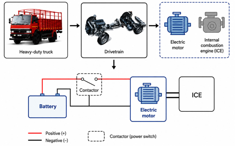
A simplified architecture of a conventional heavy-duty vehicle drivetrain is shown in
Figure 1. The main system components comprise a battery pack, a high-current-carrying contactor, a starter motor, and an ICE. The battery serves as the primary source of electrical energy, supplying high currents required during engine start-up. The contactor acts as an electrically controlled switch, regulating the connection between the battery and the starter motor. Upon activation, the starter motor converts electrical energy into mechanical torque to initiate combustion within the ICE.
Each component within this system imposes specific performance requirements. The battery must be capable of delivering high transient currents while maintaining voltage stability under varying thermal and load conditions. The starter motor is required to generate sufficient torque, and the ICE must reliably achieve ignition and transition to sustained operation. The contactor, positioned between the battery and the starter motor, must handle high inrush currents, provide rapid and reliable switching, and withstand electrical arcing during operation. The contactor must also endure harsh environmental conditions, including vibration and temperature fluctuations.
Given these demanding requirements, the development of a high-performance contactor able to operate with large currents is essential to improving system reliability, efficiency, and safety. This work focuses on the design of the active parts of such a contactor, with a main design constraint related to keeping its mass and volume within the assumed limits. The requirements for the performance of the contactor and the main dimensional constraints are reported in
Table 1.
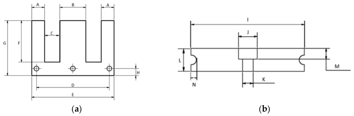
As is common in most automotive applications, a stringent constraint is that of cost and therefore, for this work, it was decided to utilise material cores with standard templates such as EI-cores that are readily available [
12].
Figure 2 shows the geometry of such cores.
The main contacts must be sized according to the current that flows through them, as they form the primary conductive path which carries the full load current when the device is in operation. The design specification for this contactor is 1300 A for 60 s. Therefore, the contacts must be designed to withstand the high current levels without excessive heating or mechanical degradation. Furthermore, they are dimensioned to minimise contact resistance or localised heating and reduce the risk of failure.
Copper is chosen for this application due to its high electrical conductivity, mechanical strength and freedom from corrosion, which allow it to maintain performance even at elevated temperatures [
13]. The sizing is chosen, ensuring that the conductor cross-sectional area is sufficient to absorb the generated heat without exceeding temperature limits and is determined based on standard practices for copper conductors, considering current density limits and the allowable temperature rise, according to [
14].
3. Analytical Modelling and Analysis
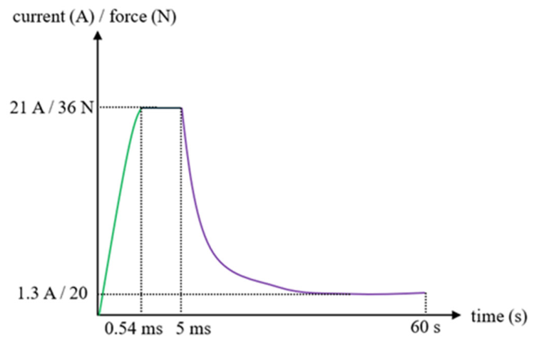
Having defined a design window and the magnetic core of the design, this section then deals with the analytical modelling of the contactor. The operational cycle required is as shown in
Figure 3, which highlights the current required for the actuation of the coil.
The force required for closing the contactor consists of the sum of the forces to compress the spring to overcome friction and that due to the weight of the moving part, thus allowing for the value of the force needed to be determined. This force must be equal to the magnetic force produced by the contactor, which can be expressed as in (1), where B is the flux density, H is the magnetic field and A is the airgap surface.
The magnetic field
can be expressed as a function of the induction B and the permeability of free space
according to the magnetic characterisation of materials B=
. So, by imposing a desired induction value inside the airgap (generally 0.7–1 T), the cross-sectional surface at the airgap value to obtain the desired force can be found by (2).
For this work, the most suitable readily available core was found to be the E-core from the EI42 and the I-core from the EI48 single-phase laminations series [
12], which fit perfectly within the dimension limits given in
Table 1, while allowing for maximum utilisation of the magnetic circuit required for the design. The dimensions of the chosen core are reported in
Table 2.
By neglecting the iron path, the flux density can be expressed according to (3), where
is the number of turns of the coil,
is the current and
is the airgap distance.
Thanks to this linearisation of the problem, the magnetomotive force needed to produce the desired force can be found as in (4).
As a consequence, the force can also be expressed as a function of the magnetomotive force and the airgap according to (5).
Considering that full closure is not achieved immediately (due to the bouncing effects), a reduced holding force and associated holding current must be derived by using (5). Since the analytical model neglects saturation effects and nonlinearities in the BH curve, deviations of the results at small air gaps are expected.
The inductance of the system can be determined through classical inductance methods such as that given by (6), where
is the voltage supplied to the electromagnetic circuit,
is the inductance of the EI-core system,
is the rate of change in current and
is the effective resistance of the copper winding. The proposed actuator is designed for fast transient operation, with actuation times significantly shorter than the thermal time constant of the winding. Consequently, the copper resistance was assumed constant and evaluated at the reference ambient temperature of 40 °C. Under these conditions, self-heating effects during a single actuation are negligible, while temperature-dependent magnetic property variations are expected to have a secondary influence on the transient response.
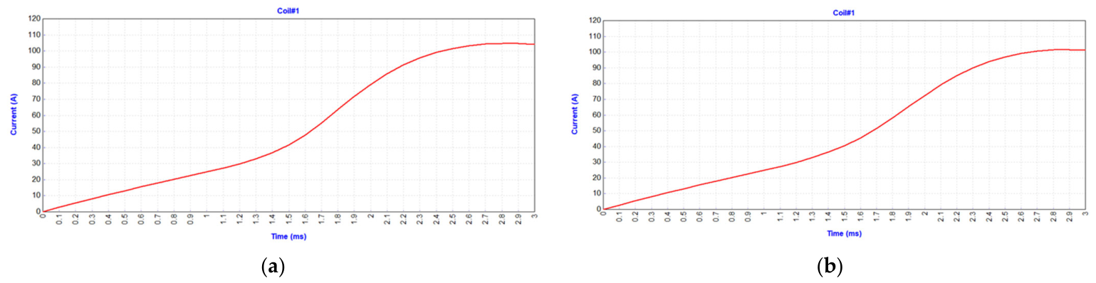
The solution to (6), assuming zero initial conditions, is reported in (7), where t is the time taken for the current to rise from 0 to the holding current with the moving part closed,
is the time constant of the system and I(t) is the peak current reached.
The main constraint for the application is the closure time, so the number of turns for the coil must be designed in order to have an inductance value that allows for meeting the requirements, which can be written as a function of the number of turns
and the reluctance of the system
according to (8). For this application, the number of turns is found to be 90.
It is important to note that the analytical model assumes linear magnetic behaviour, neglecting both magnetic saturation and nonlinear B–H characteristics of the core material. As a result, the model is expected to provide higher accuracy within the linear operating region, while deviations may occur at higher current levels where the core approaches saturation, particularly at small air gaps. In addition, magnetic properties are temperature-dependent and may vary at elevated temperatures, particularly in terms of permeability and iron losses. However, in the present work, the contactor is intended for short-duration cold cranking operations, characterised by transient activation times on the order of a few milli-seconds.
5. Experimental Validation
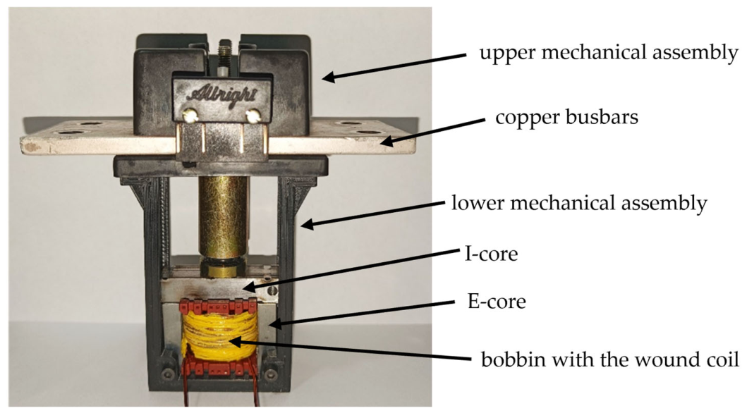
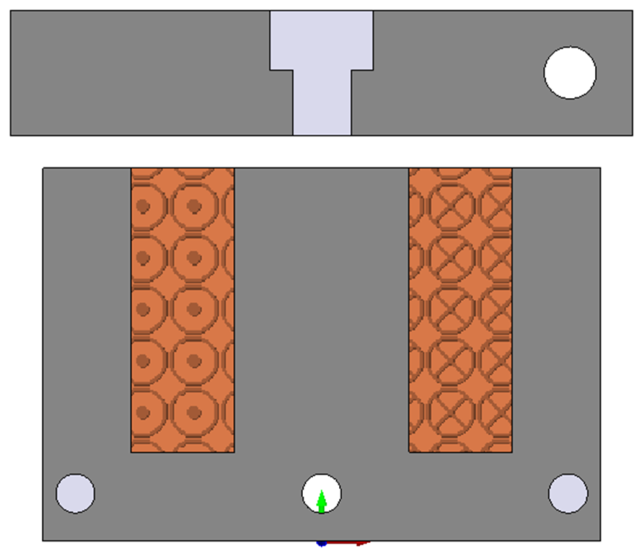
To validate the modelling procedures proposed and discussed above, an experimental prototype of the system shown in
Figure 5 was built in-house. The exact dimensions, materials and winding configuration used in
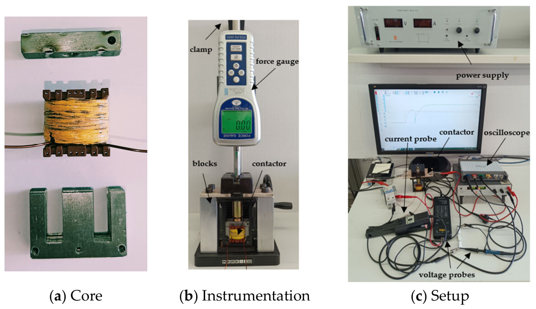
Figure 5 were replicated in the prototype, which is shown in
Figure 7a.
It is important to highlight that the experimental validation was specifically aimed at validating the electromagnetic actuator behaviour, rather than performing full load electrical tests on the main power contacts. Therefore, the present study does not include experimental verification under nominal 1300 A switching conditions, nor analyses of arc phenomena, contact wear, or long-term thermal performance. The contactor with its mechanical assembly is shown in
Figure 7b.
The complete prototype is reported in
Figure 8.
5.1. The Setup
As this work serves mainly as a proof of concept for the electromagnetic design of the contactor, for testing purposes, the mechanical assembly of an existing industrial contactor was used. This was removed from said industrial contactor and customised and fitted to the contactor core shown in
Figure 7a. The main customisation procedures include a minor re-design of the lower housing, the inclusion of guides to direct the motion of the I-core, two blocks to hold the contactor in place and a clamp to hold the force gauge sensor. The resulting prototype is shown in
Figure 7b, while
Figure 7c shows the whole experimental setup required for the testing regime, where the PCE-FG 20 SD force gauge has a 0.02 N resolution.
It is important to note that the experimental prototype focuses primarily on validating the electromagnetic actuator. The mechanical assembly is derived from a modified industrial contactor and does not fully represent a final integrated design optimised for the specific application. As a result, factors such as friction, alignment tolerances, and contact dynamics may differ from those of a purpose-built contactor. These simplifications are not expected to significantly affect the static force validation but may influence dynamic characteristics such as closure speed and contact bounce.
5.2. Testing and Results
A testing regime reflecting the modelling sequences described above was initiated for the contactor, where the main input variable was the voltage source coming from the DC supply. In practice, this input voltage will be set by the vehicle’s battery specifications, but for the purpose of model validation, the input was raised in steps with the power supply on a current limit configuration. For each input voltage, the main measurements recorded were the voltage across the coil, the current in the coil and the force measurement provided by the force gauge. Here, it is important to note that to achieve as accurate results as possible, the weight of the customised mechanical assembly was measured beforehand and derived to amount to approximately 1 N. In all subsequent results, this was then subtracted from the total force generated by the magnetic core.
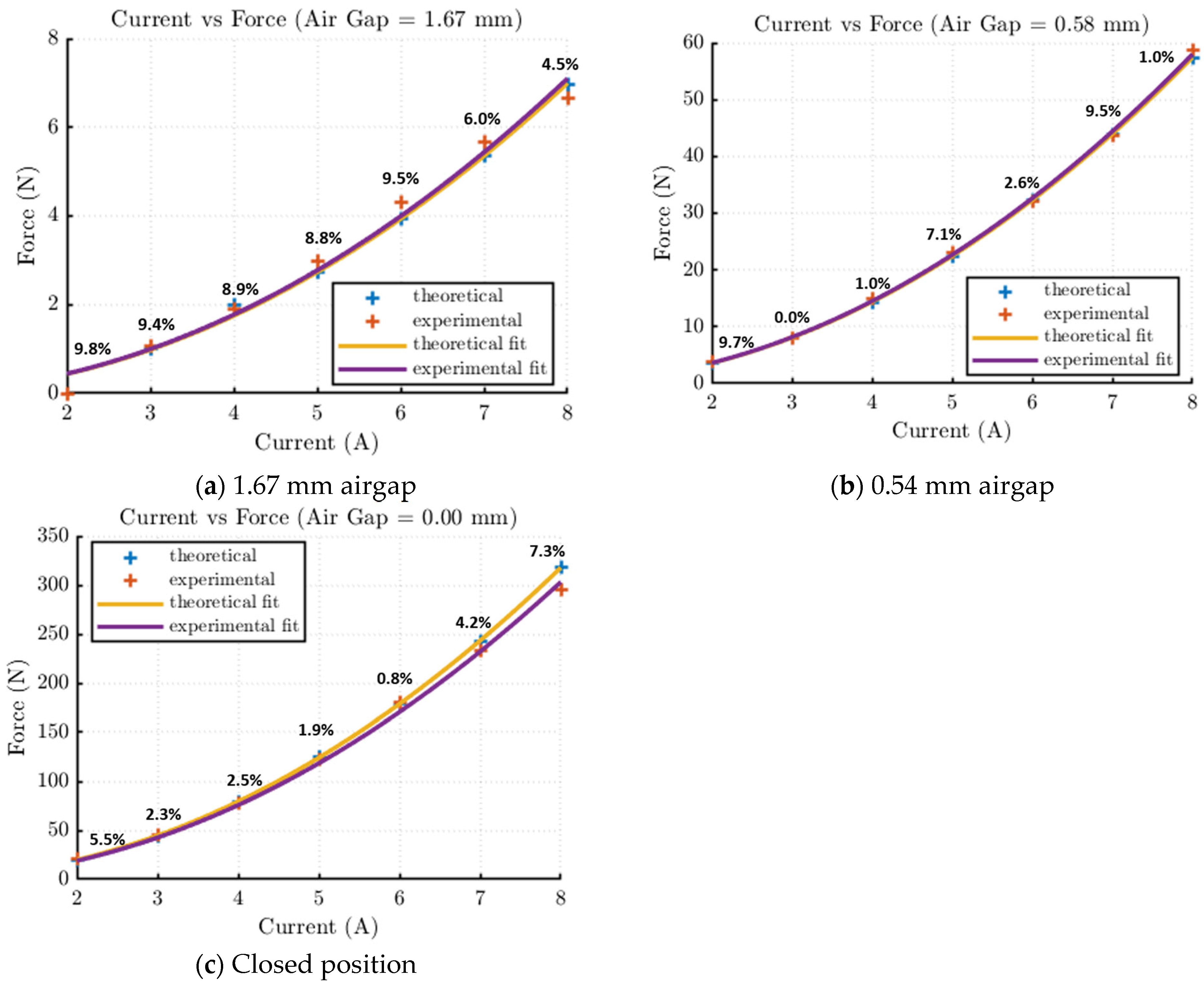
The experimental results for an increasing input coil voltage (and hence coil current) are shown in
Figure 8, where comparisons between the analytical (theoretical) and the experimental results are given.
Figure 9a gives the results when the mover is in a position that results in a 1.67 mm airgap.
Figure 9b,c give similar results when the airgap is 0.58 mm and fully closed respectively. It is important to note that to reduce measurement errors, each experimental test was repeated three times; thus, the experimental results shown in
Figure 8 are the average values of these three tests for each test scenario. The percentage discrepancy between the theoretical and measured value is highlighted near every point in the figures.
5.3. Discussion
The experimental results presented in
Table 4 and
Figure 8 demonstrate a strong correlation between the analytical predictions and the measured electromagnetic force produced by the prototype contactor. The percentage error between analytical and experimental results remained below 10% across the full operating range, with the majority of points showing errors below 5%. This level of agreement validates the analytical modelling approach used in the design stage and confirms that the simplified magnetic circuit model provides a sufficiently accurate prediction of the contactor force for design purposes. The results also confirm the expected quasi-quadratic relationship between the electromagnetic force and coil current, as predicted by the analytical formulation. This relationship is particularly important for contactor design because it shows that relatively small increases in coil current result in significant increases in closing force. Thus, the designer can trade off coil current, number of turns, and available supply voltage to achieve the required closing force while minimising copper losses and thermal stress.
To further contextualise the results, the proposed design can be compared with typical high-current DC contactors reported in the literature and industry, which often exhibit higher inductance and consequently slower actuation times, typically exceeding 10 ms. In contrast, the developed contactor achieves operation at up to 1300 A with a target closure time of approximately 5 ms within strict dimensional constraints. This improvement is primarily attributed to the optimisation of the magnetic circuit and reduced inductance, which enable faster current rise. Additionally, the achieved force levels within a compact volume indicate a favourable force-to-size ratio, highlighting the suitability of the proposed approach for space-constrained automotive applications. A summary comparison between typical high-current DC contactors reported in the literature and industry practice ([
16,
17]) and the proposed design is provided in
Table 4, which shows that the proposed design achieves improved actuation speed and compactness while maintaining comparable current handling capability, highlighting its suitability for cold cranking applications.
Table 4 provides a qualitative overview of state-of-the-art high-current contactor solutions reported in the literature and commercial domain. Since the considered devices are designed for different operating conditions, current ratings, and application requirements, the comparison is intended to highlight general design trends and limitations rather than provide a direct one-to-one quantitative benchmarking.
The influence of magnetic saturation can be further assessed by examining the deviation between analytical and experimental results across the operating range. As shown in
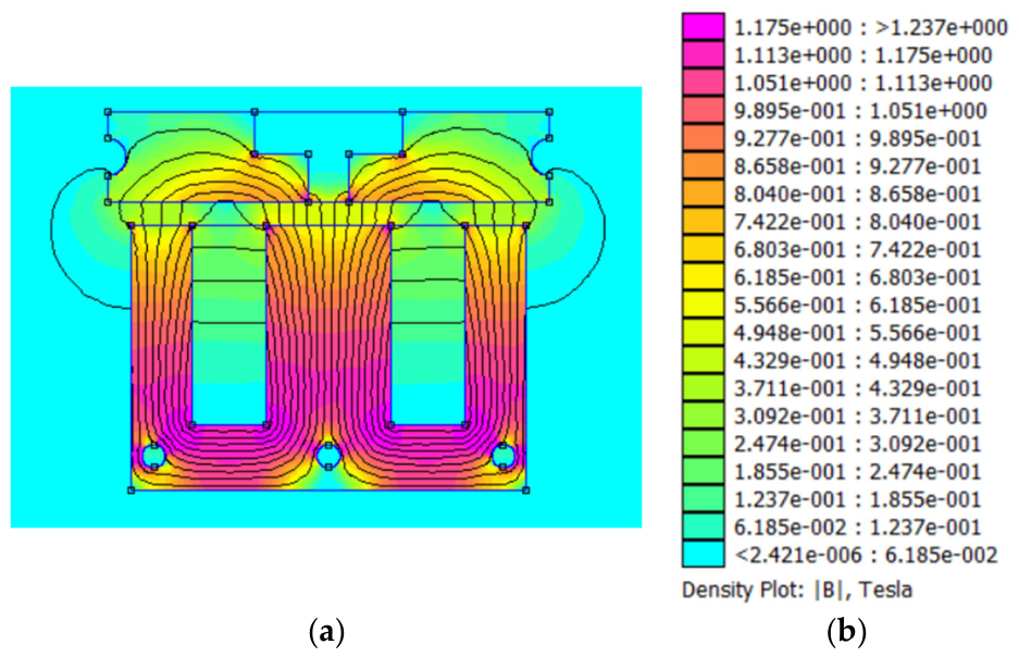
Figure 7, the percentage error remains relatively low (<5%) for coil currents up to approximately 5–6 A, indicating that the magnetic circuit operates predominantly in the linear region. At higher current levels (7–8 A), the error increases to approximately 7–8%, which can be attributed to the onset of magnetic saturation in the core material. This behaviour is consistent with the FE results, where higher flux densities are observed in localised regions of the core. These results, therefore, quantify the impact of neglecting nonlinear magnetic behaviour and confirm that the analytical model slightly overestimates force at higher excitation levels. Additional contributing factors include mechanical friction, minor misalignment in the prototype assembly, and measurement uncertainties associated with the force gauge and current measurements. Despite these factors, the error remains within an acceptable range for engineering design and validates the use of the analytical model as a first-stage design tool.
The comparison between solid and laminated cores discussed in the modelling section also has important design implications. Since the device operates under DC excitation, eddy current losses are minimal during steady-state operation, and therefore, the use of solid cores can be justified from a cost and manufacturing perspective. However, the laminated core configuration resulted in a slightly lower inductance and therefore a faster current rise time, which directly contributes to faster contactor closing time. Given that closing time is one of the key design constraints in cold cranking applications, this result suggests that laminated cores may still provide performance benefits despite the DC nature of the application. Thus, from equation (8), assuming a typical coil resistance of the order of 1–2 Ω, the obtained inductance (~0.8 mH) results in an electrical time constant below 1 ms, enabling the current to reach the required actuation level within the 5 ms closure time constraint. In contrast, typical contactors with inductance exceeding 4 mH exhibit significantly slower current rise, leading to closure times above 10 ms.
From a system-level perspective, the electromagnetic actuator behaviour must be considered in conjunction with the electrical characteristics of the battery during cold cranking. Under such conditions, significant voltage sag occurs due to the high current demand and increased internal resistance at low temperatures. This directly affects the coil excitation voltage and, therefore, the current rise profile governed by (6) and (7). The relatively low inductance achieved in this design (~0.8 mH) enables a rapid current build-up even under reduced voltage conditions, supporting the required fast closure time (~5 ms). While the present experimental validation is performed under controlled supply conditions, the results indicate that the proposed design is well-suited to maintain reliable actuation under realistic cold cranking transients. A fully coupled electro-thermal-mechanical system validation will be addressed in future work.
Despite the strong agreement between analytical, numerical, and experimental results, the present study has, of course, some limitations that should be acknowledged. In fact, the analysis focuses primarily on the electromagnetic actuation and does not include a detailed thermal assessment under repeated high-current cranking cycles, where temperature rise may affect both coil resistance and contact performance. Also, the behaviour of the electrical contacts, including contact stress, erosion, and arc dynamics during switching, is not explicitly modelled, although these effects are critical for long-term reliability. It is also true that the analytical model assumes linear magnetic behaviour and neglects saturation effects outside the validated operating range, which may introduce deviations at higher excitation levels. Finally, the experimental validation is based on a simplified mechanical prototype, which does not fully capture dynamic effects such as contact bounce, damping, and wear. These limitations define the scope of the present work and highlight areas requiring further investigation.
6. Conclusions and Future Developments
This paper presented the design, modelling, and experimental validation of a compact high-performance electromagnetic contactor intended for high-current cold cranking applications in heavy-duty vehicles. The work focused on the electromagnetic actuator design, including magnetic circuit sizing, coil design, and force prediction, under strict dimensional and performance constraints.
An analytical model of the magnetic circuit was used to determine the required coil current, number of turns, and expected electromagnetic force. The analytical results were validated using FE simulations, which showed very close agreement in terms of predicted force and inductance. A physical prototype was constructed and experimentally tested to validate the modelling methodology. The experimental measurements showed good agreement with the analytical predictions, with errors remaining below 10% across the tested operating range. This confirms that the analytical model can be reliably used as a design tool for preliminary sizing and optimisation of electromagnetic contactors.
The results presented in this paper demonstrate that it is possible to design a compact electromagnetic contactor capable of producing the required closing force for high-current cold cranking applications while meeting strict dimensional constraints. The study also highlights the importance of considering magnetic material selection, inductance, and current rise time when designing fast-acting contactors for battery-powered systems.
Future work will focus on extending the present electromagnetic design toward a fully integrated and application-ready contactor system. Priority will be given to (i) thermal modelling and experimental validation under repeated cold cranking cycles, to assess temperature rise and its impact on coil resistance and efficiency; (ii) detailed analysis of contact behaviour, including arc formation, contact erosion, and mechanical stress, to ensure long-term reliability under high-current switching; (iii) dynamic system modelling, incorporating coupled electromagnetic and mechanical effects to analyse closure time, contact bounce, and transient response under realistic supply conditions; and (iv) design optimisation for mass and volumetric efficiency to further improve integration within battery systems. These developments will build directly on the findings of this work, particularly the demonstrated relationship between inductance, current rise, and actuation speed, and will enable the transition from a validated electromagnetic prototype to a fully engineered industrial solution.
Overall, the methodology presented in this work provides a practical framework for the design and development of high-performance DC contactors for harsh environment and high-current automotive applications.