1. Introduction
Unmanned spherical robots, characterized by a fully enclosed spherical shell, integrate the shell with internal drive and power systems, enabling omnidirectional mobility [
1]. Due to the fully enclosed structure, spherical robots exhibit significant advantages in traversing complex outdoor environments involving dust and humidity, compared to traditional wheeled or legged robotic systems [
2]. This characteristic endows spherical robots with enhanced protection and traversability, making them particularly suitable for unmanned field operations such as disaster recovery and exploration [
3,
4].
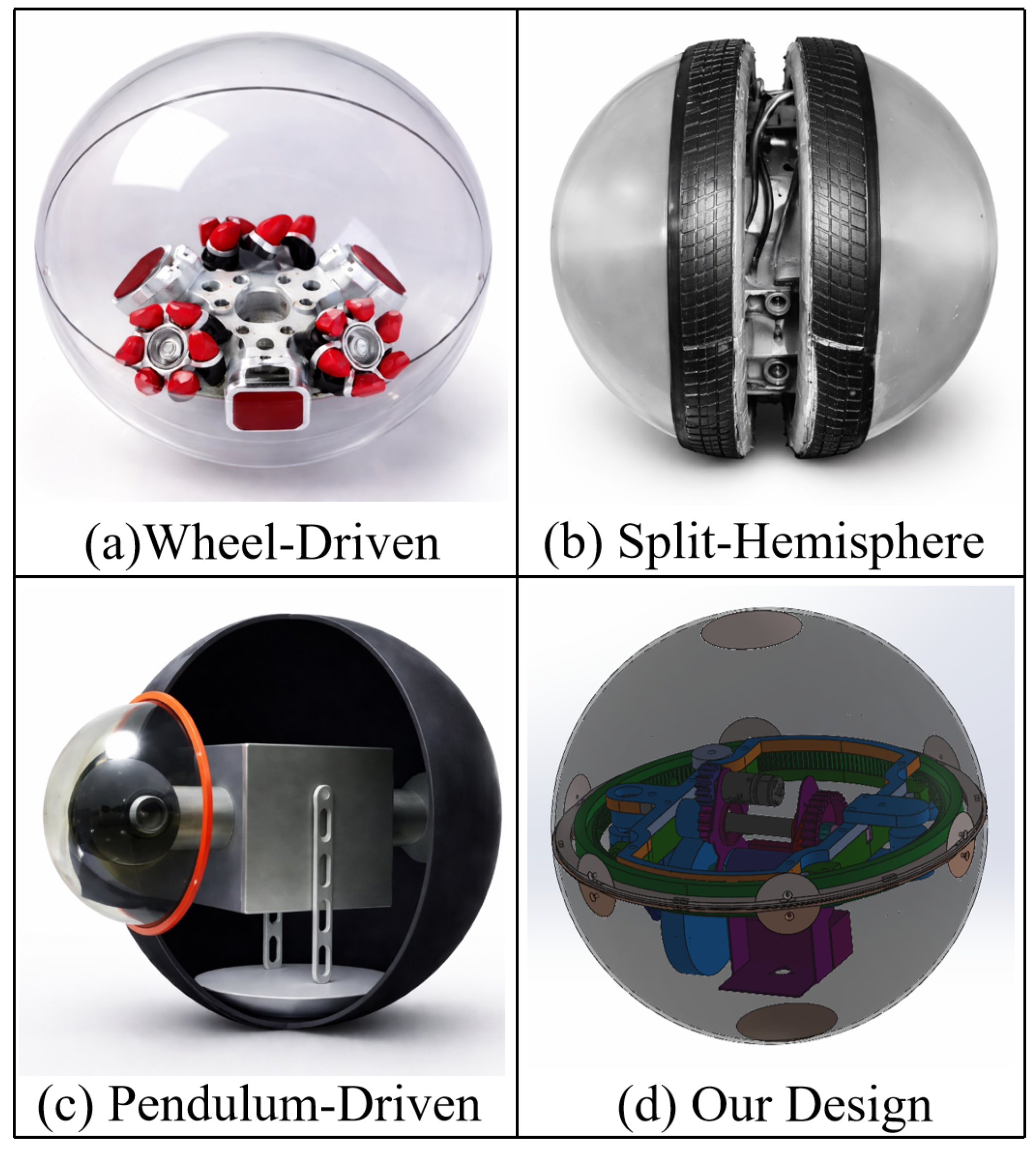
In recent years, various design approaches for unmanned spherical robots have been proposed, as illustrated in
Figure 1. These approaches include wheelbase internal mechanisms, split-hemisphere structures, or gravity pendulum-driven systems [
5,
6]. Each design presents distinct advantages and limitations in unmanned robotic applications. Wheelbase driven mechanisms excel in speed and control performance [
7,
8]; however, their efficiency significantly degrades in complex terrains due to increased energy losses. Reaction wheel and split-hemisphere designs transmit power directly to the ground, offering strong maneuverability; however, their nonenclosed spherical structures limit environmental protection capabilities, which is a critical concern for unmanned operations [
9,
10]. Gravity pendulum-driven systems are compact and energy-efficient due to their transmission principles and structural characteristics, but suffer from insufficient power output, limited instantaneous thrust, and coupled dynamics, which restrict turning agility in unmanned spherical robot applications [
11].
Unmanned spherical robots offer broad application potential, yet their design and control remain challenging. A major challenge stems from the inherent coupling between rolling and yaw motions, which significantly increases the complexity of attitude regulation and path planning in unmanned robotic systems. Moreover, many existing unmanned spherical robots exhibit limited turning agility, restricting their operational effectiveness in confined or complex environments [
12,
13]. Among existing actuation mechanisms, pendulum-driven systems are widely adopted due to their high energy efficiency and structural simplicity. Nevertheless, such systems are subject to nonholonomic constraints that couple translational and rotational motions, leading to large turning radii and slow steering response [
14]. Consequently, improving maneuverability without sacrificing energy efficiency remains a key unresolved challenge for pendulum-driven unmanned spherical robots [
15].
To address these challenges in unmanned spherical robots, a promising solution is the mechanical decoupling of rolling and turning motions [
16,
17]. Such decoupling enables independent control of translational and rotational motions, allowing zero-radius turning while maintaining efficient straight-line rolling. This approach not only simplifies the mechanical structure but also improves control performance and motion accuracy in unmanned spherical robot applications [
18].
In this work, a mechanically decoupled actuation system for unmanned spherical robots is proposed, consisting of a pendulum-driven rolling mechanism and a circular gear rack-based turning mechanism [
19]. The pendulum mechanism generates translational motion by shifting the robot’s center of mass, while the turning mechanism enables precise in-place orientation adjustment through an internal circular gear rack [
20]. This design allows independent execution of linear and rotational motions, thereby enhancing motion flexibility and improving traversability in practical unmanned applications [
21].
The main contributions of this article are as follows:
A mechanically decoupled actuation system for unmanned spherical robots that integrates a pendulum-driven rolling mechanism with a circular gear rack-based turning mechanism, enabling a zero turning radius and enhancing traversability.
A dynamic modeling and control framework that captures the nonholonomic rolling constraints and provides a control-oriented basis for rolling and turning analysis under representative surface conditions.
Comprehensive validation through simulations and unmanned spherical robot prototype experiments, demonstrating improved turning response and terrain adaptability.
2. Spherical Robot Dynamic Analysis
This section analyzes the dynamics of the pendulum-driven spherical robot, where pendulum displacement shifts the center of mass(CoM) to achieve controlled rolling through gravitational and inertial forces [
22]. By examining the dynamics of both the pendulum and shell, the fundamental principles of motion are revealed, providing theoretical support for control optimization and enhanced robot maneuverability [
23].
2.1. Pendulum-Driven Motion
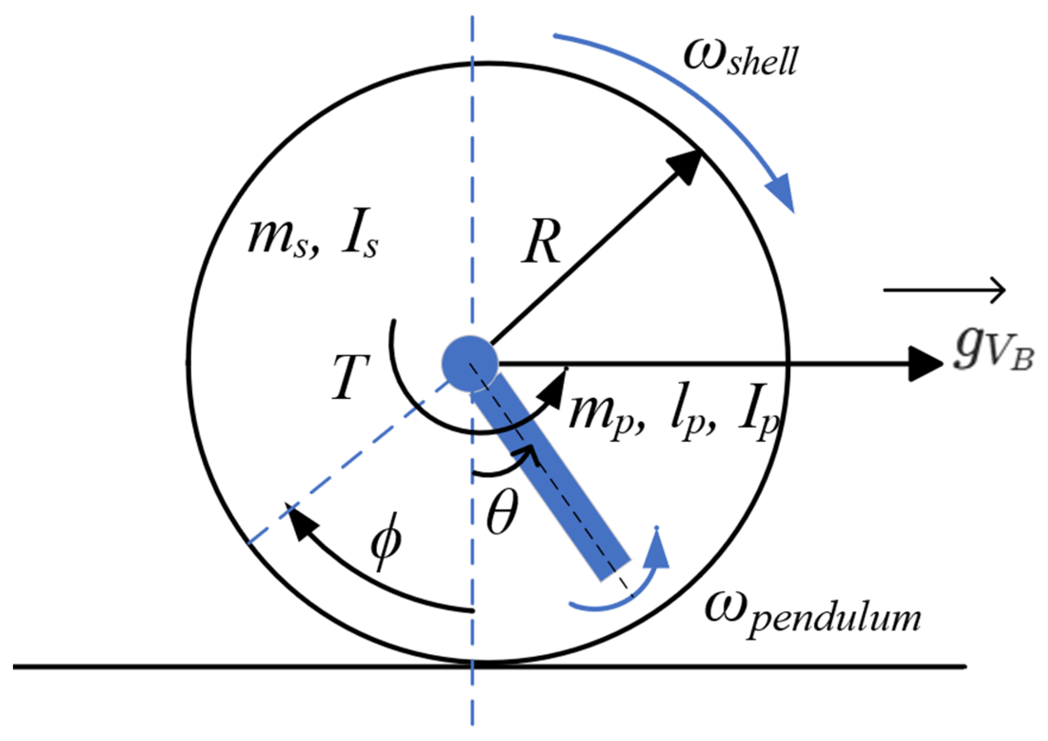
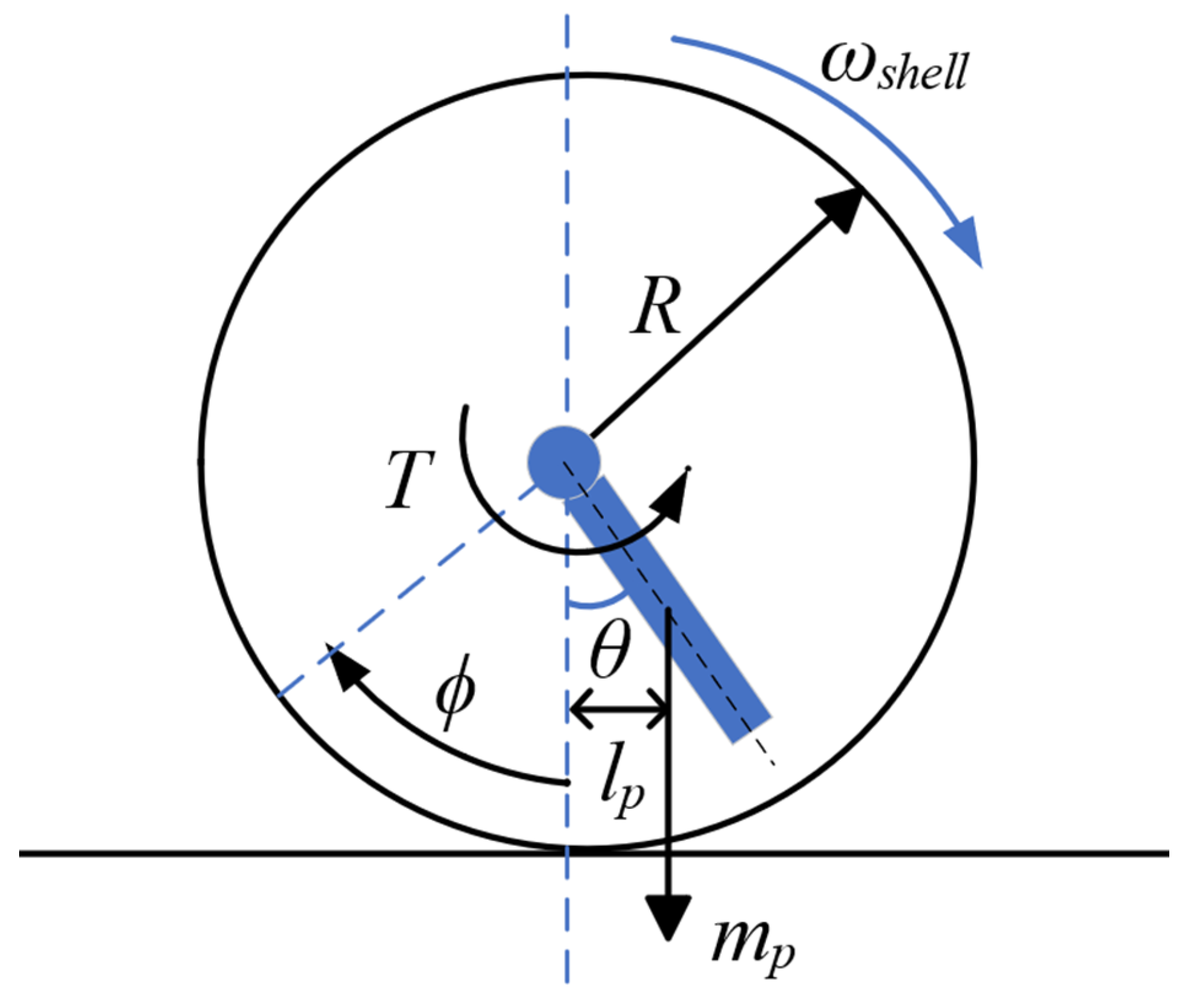
Pendulum-driven locomotion is achieved by shifting the system center of mass (CoM) using an internal pendulum. When the pendulum deflects from its vertical equilibrium, the CoM offset generates a gravitational restoring torque that drives the spherical shell to roll, as illustrated in
Figure 2. In the following,
R denotes the shell radius,
the pendulum mass, and
the distance from the pendulum pivot to its center of mass. The restoring torque is given by
where
g is the gravitational acceleration and
is the pendulum deflection angle from the vertical.
In practice, the shell motion is governed by the interplay between this restoring torque, the shell inertia, and the ground contact conditions. Therefore, in the next subsection we derive the corresponding torque requirements and the no-slip condition, which jointly determine the admissible actuation range for stable rolling. This restoring torque provides the fundamental actuation principle for pendulum-driven rolling.
2.2. Dynamics and Torque Generation
The rolling capability of a pendulum-driven spherical robot is mainly determined by the pendulum parameters
and the ground contact conditions. The gravitational restoring torque
is given in Equation (
1). To initiate forward rolling, the actuation torque
T must overcome the restoring torque:
Friction at the contact point is required to avoid slip. The normal force
N and the corresponding static friction limit are
where
denotes the mass of the shell/frame excluding the pendulum, and
is the coefficient of static friction between the shell and the ground (dimensionless). The resisting torque due to friction is
Under the no-slip condition, the actuation torque must satisfy
Combining the above inequalities, the admissible torque range for pure rolling can be written as
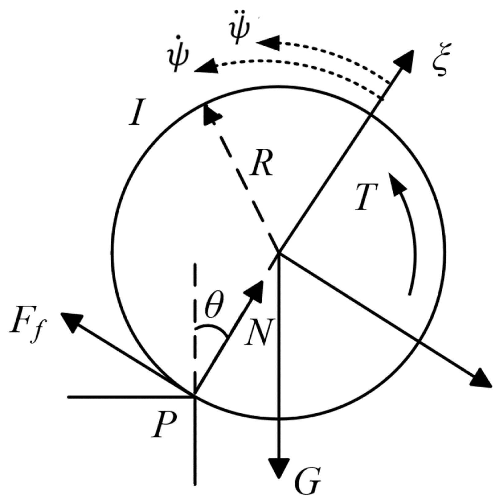
When climbing a slope or traversing small obstacles, the effective gravitational component opposing motion increases, which raises the required actuation torque and tightens the no-slip constraint [
24].
Figure 3 illustrates the force components during slope ascent, including the weight
, the normal force
N, the friction force
, and the applied torque
T at the contact point
P.
This analysis guides actuator sizing and parameter selection for robust terrain traversal.
2.3. Dynamic Modeling of the Spherical Robot
The spherical robot is modeled as a multibody system consisting of an outer shell, an internal pendulum, and a circular gear-rack turning mechanism. Rolling is assumed to occur without slipping. The pendulum actuator generates the primary rolling torque, while the circular rack enables in-place turning of the internal bracket.
To describe both locomotion and internal actuation, the generalized coordinates are defined as
where
denote the shell center position,
is the yaw (heading) angle of the shell,
is the pendulum swing angle, and
is the rotation angle of the central bracket (internal frame) driven by the turning mechanism. A separate variable,
, is introduced below to denote the shell rolling angle used in the no-slip rolling constraint.
The Lagrangian is defined as
where
K and
V are the total kinetic and potential energies, respectively.
To ensure pure rolling, the nonholonomic no-slip constraints are imposed as
where
denotes the shell rolling angle and
is the corresponding rolling angular velocity.
Using the Euler–Lagrange method, the equations of motion can be written in compact form:
where
is the mass matrix,
collects Coriolis/centrifugal terms,
is the gravity vector, and
denotes damping/friction terms. The input vector can be written as
, corresponding to the actuation torques applied to the pendulum drive and the turning mechanism, respectively;
is the associated input mapping (selection) matrix.
The Equations (
8)–(
11) provide a compact description of the coupled dynamics and define the variables used in the controller and simulation analysis. In this work, the analytical model is mainly used for physical insight and parameter selection, whereas the closed-loop performance is evaluated in MuJoCo using forward dynamics with contact interactions. The inertial properties are obtained from geometric approximations based on measured mass and dimensions (e.g., a uniform hollow-sphere approximation for the shell), rather than explicitly deriving and presenting full analytical mass-matrix expressions.
3. Hardware
This section introduces the hardware architecture of the spherical robot, which adopts a mechanically decoupled design of rolling and yaw motion. This enables efficient rolling and zero-radius precise turning across various terrains while maintaining a compact and reliable structure [
25].
3.1. System Architecture and Spherical Shell
The hardware architecture consists of an outer spherical shell and two independent actuation subsystems for rolling and turning. The rolling subsystem generates motion by shifting the pendulum CoM, whereas the turning subsystem employs a compact circular gear-rack mechanism to steer the shell. This mechanically decoupled architecture reduces dynamic interference between rolling and yaw motions and improves stability during combined maneuvers.
The prototype has a shell radius of 0.15 m and a measured total mass of 9.1 kg. A conservative upper-bound mass constraint of 10 kg was adopted for actuator sizing and robustness, accounting for the protective shell, onboard power supply, and impact resistance required for outdoor operation. The prototype was designed to achieve a linear velocity of 0.5 m/s and a yaw rate of 45°/s on flat ground.
The spherical shell serves both as the robot structural frame and as the primary interface with the environment. Its design emphasizes protective capability while maintaining sufficient ground traction, making it suitable for operation in unstructured environments. The shell is fabricated from high strength steel to provide the rigidity required to support the internal components. A thin-walled structure with millimeter-scale thickness is adopted to reduce additional mass while maintaining sufficient stiffness, and the outer surface is treated with a non-slip coating to enhance traction. The central bracket, which supports internal components such as the pendulum and yaw mechanism, is made of Bakelite, a heat-resistant material that balances strength and lightweight characteristics.
To further minimize subsystem interference and facilitate integration of motors and control electronics, the internal layout was designed with modular mounts and optimized cable routing, which improves maintainability and reassembly.
3.2. Pendulum Motion System
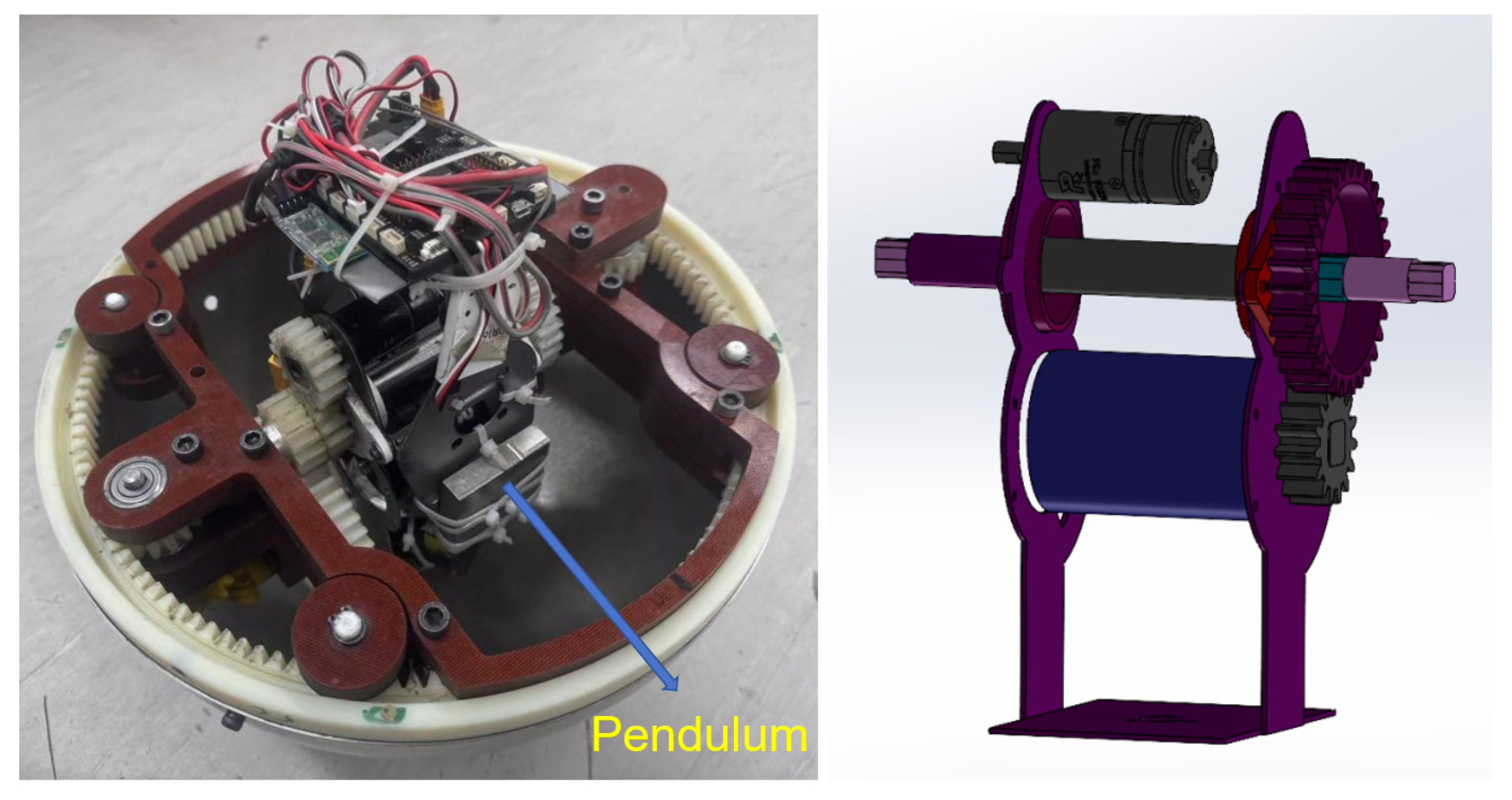
The pendulum-driven rolling subsystem is designed to provide compact torque generation inside the spherical shell. A high-density steel pendulum is mounted on a central shaft supported by two ball bearings to reduce friction and ensure stable oscillatory motion. The actuation is provided by a RoboMaster M3508 motor, and the motor torque is transmitted to the pendulum through a gear train (
Figure 4).
To ensure sufficient torque output and dynamic response, the pendulum CoM is placed close to the shell so that the gravitational offset effectively induces rolling. The internal layout keeps the CoM low and near the geometric center, improving stability during rolling and turning (
Figure 5).
The motor torque is proportional to the input current:
where
is the motor torque,
is the torque constant, and
is the motor current.
The pendulum rotational dynamics about its pivot can be approximated as
where
is the pendulum moment of inertia about the pivot,
is the pendulum angular acceleration, and
denotes damping/friction torque. A lumped-mass approximation is used:
The M3508 motor includes a 19:1 planetary gearbox and an additional external 2:1 reduction stage; therefore, the overall reduction ratio is
. After transmission, the torque applied to the pendulum is
where
is the transmission efficiency.
When the pendulum deviates from equilibrium, the gravitational torque acting on the shell is
which drives the shell rolling motion. The shell inertia is approximated by a uniform hollow-sphere model:
Accordingly, the shell rolling angular acceleration (idealized, without slip) can be written as
where
denotes the shell rolling angle and
. These relations provide an order-of-magnitude estimate for actuator sizing; the closed-loop behavior with contact effects was evaluated in simulation and experiments.
3.3. Circular Gear Rack Turning System
Another subsystem is the circular gear rack turning mechanism, designed to provide independent and precise directional control. Unlike conventional approaches relying on differential drive or center-of-mass displacement, this mechanism decouples rolling and turning by meshing a motor driven pinion with a circular rack fixed on the inner surface of the spherical shell, thereby enabling accurate control of both motions.
The turning principle is realized through the relative motion between the pinion and the annular rack: when the motor drives the pinion, internal components rotate with respect to the shell, producing a net angular displacement around the vertical axis and achieving stable in-place turning.
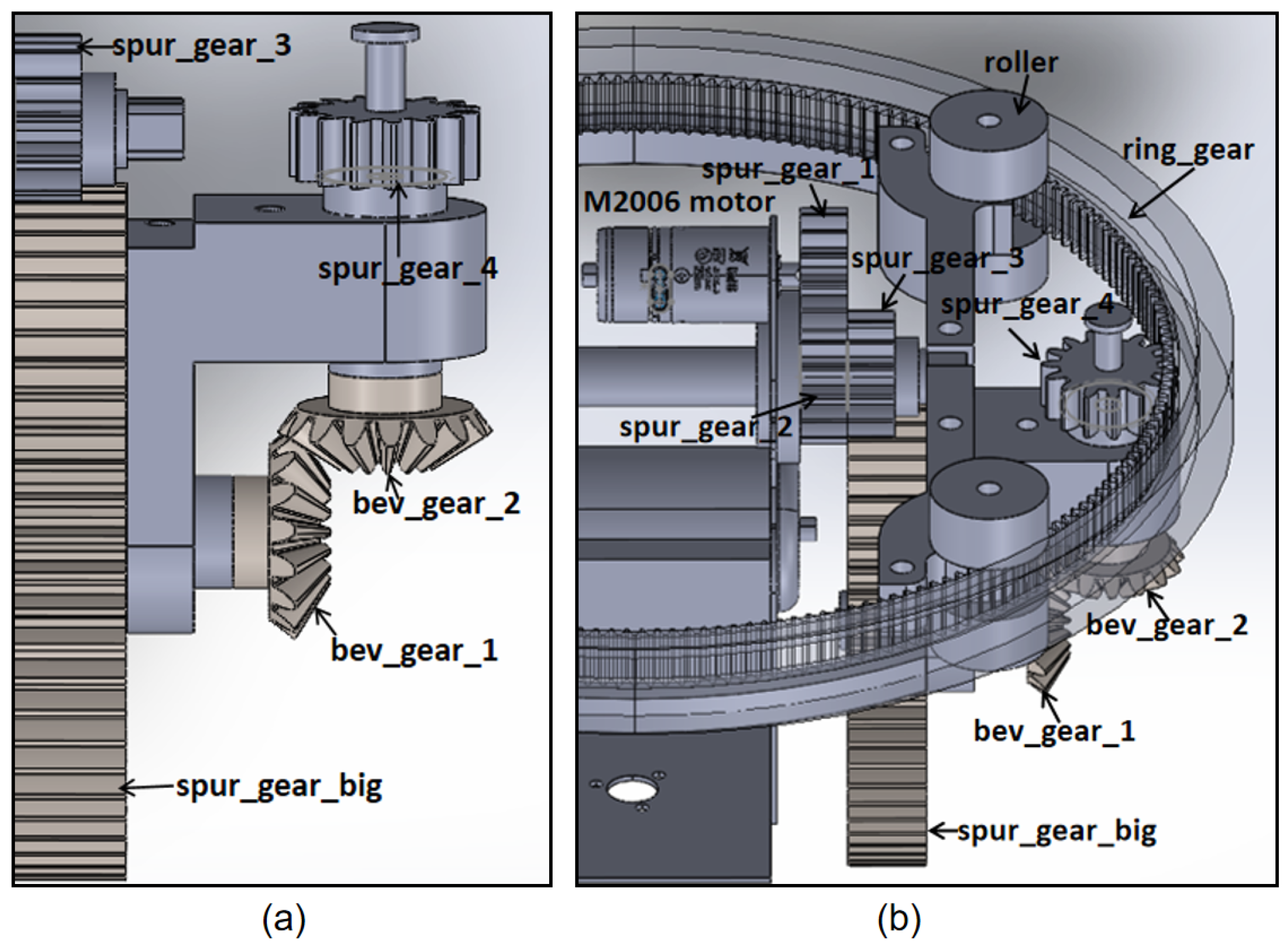
As shown in
Figure 6, the mechanism comprises a high-torque motor, multi-stage gear transmission, coaxial hollow and solid shafts, a central bracket, and a circular rack. A cascaded gear train amplifies torque and reduces speed, while bevel gears redirect power by 90° to engage the fixed rack. This configuration achieves mechanical decoupling, ensures structural stability, and provides efficient torque transmission for precise turning control.
The gear system employs the RoboMaster M2006 motor, which offers a balanced trade off among torque, speed, and compactness. With a peak torque of 3.2 N·m, it can reliably drive the rack under varying load conditions. Powered by the DJI C610 driver and controlled through a hybrid fuzzy PD algorithm, the motor minimizes overshoot and suppresses oscillations during turning.
The circular gear rack mechanism enables stable and independent heading control, while its structure ensures torque amplification and precision. The control strategy provides smooth heading adjustments, and the decoupling of rolling and turning greatly improves the spherical robot’s maneuverability and adaptability in unstructured environments.
From a kinematic perspective, the pinion’s angular displacement
generates the rack displacement
x:
This is directly converted into the shell’s angular displacement
:
For
mm,
mm, and
rad, the resulting shell displacement is
The gear system introduces a motion scaling effect: while the spherical shell undergoes a smaller angular displacement than the pinion, the gear ratio amplifies output torque, ensuring smooth and energy-efficient turning with precise heading control under varying loads. Torque applied to the pinion is transferred via the rack rigidly fixed to the shell, producing a reaction torque that drives the shell to rotate about the yaw axis.
This subsystem design completes the mechanical structure for turning and rolling, enhancing the spherical robot’s turning capability and enabling zero-radius turning.
3.4. System Design
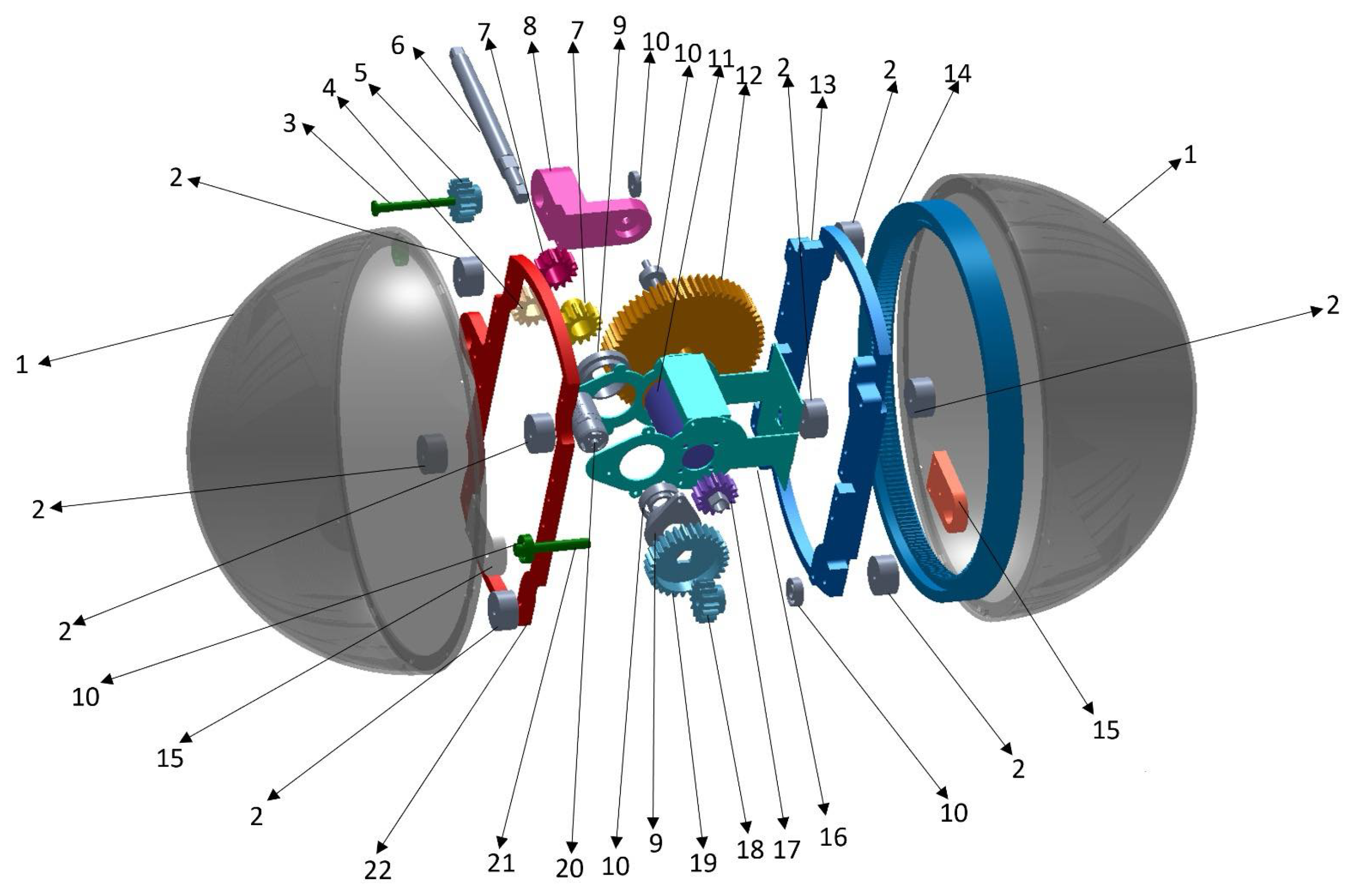
The spherical robot integrates the outer shell and all subsystems into a unified and optimized structure that fulfills the predefined design requirements. As illustrated in
Figure 7, the hardware design adopts a modular assembly strategy to ensure seamless integration and reliable operation of all components.
Control and sensing run on the RoboMaster STM32 board with CAN and UART interfaces for real-time communication. Outer loops operate at 100–200 Hz, and motor drivers regulate current at the kilohertz scale. Safety features include IMU and encoder checks, thermal and current monitoring, and automatic current ramp-down. Bluetooth telemetry enables real-time state monitoring and parameter tuning, while IMU feedback provides roll, pitch, and yaw stabilization against terrain disturbances.
The power system uses a high-capacity 16.8 V battery that is symmetrically distributed inside the shell to maintain mass balance. This layout ensures sufficient current for heavy duty motor operation while simultaneously powering the control electronics and sensors. Power management is optimized to extend endurance, which is critical for long-duration field tasks.
The prototype design emphasizes modularity and ease of maintenance. Motor mounts, gear assemblies, and sensor modules are precisely manufactured with composite materials to ensure reliable long-term operation. The heaviest components, including the pendulum and motors, are positioned near the geometric center to balance mass, reduce the moment of inertia, and enhance yaw stability. Assembly tests validated the design, confirming the interference free operation of the mechanical subsystems. Modular wiring and optimized cable routing further improve maintainability and reassembly.
Table 1 summarizes the key physical and actuation parameters that guided the modeling, control design, and experimental testing.
4. Control System Design for Spherical Robot
This section introduces the design of a fuzzy PD controller that coordinates the pendulum and turning mechanisms. Although mechanically decoupled, the two subsystems must operate in dynamic synchrony to ensure robust motion [
26,
27]. By integrating fuzzy logic with PD control, the proportional and derivative gains are adaptively tuned in real time based on instantaneous errors and their rates of change, thereby improving system stability and robustness [
28].
4.1. Fuzzy PD Controller for Motor Rotation
To achieve smooth and continuous rolling, a fuzzy PD control architecture coordinates the pendulum-driven system and the gear rack turning mechanism. Each actuator is governed by a feedback loop: the outer loop drives the pendulum motor to shift the center of mass for rolling, while the inner loop regulates yaw for directional stability. Gains are adaptively tuned in real time using IMU feedback, enabling smooth trajectory tracking, reduced overshoot, and improved energy efficiency. Shared sensor feedback allows coordinated gain adaptation, and compared with conventional PID control, the fuzzy PD approach demonstrates superior robustness under uncertainties.
During turning, a fuzzy PD controller ensures accurate yaw control and overall stability. The steering motor regulates the yaw angle, while the pendulum motor maintains balance to avoid mass offset. The fuzzy PD controller adaptively tunes the gains, computes the desired angular acceleration, and drives the central bracket via inverse dynamics. Real-time IMU roll feedback suppresses oscillations from inertial coupling, enabling stable in-place rotations.
The fuzzy PD controller employs a fuzzy inference system to dynamically adjust control parameters. The real-time error e and error change are fuzzified and processed through rule bases to determine proportional () and derivative () gains. These rules accelerate error correction, reduce overshoot, and improve stability. Representative rule tables for and are shown below.
Proportional Gain (Kp) Rule Base:
| Error/ΔError | NB | NM | NS | ZO | PS | PM | PB |
| NB | PB | PB | PM | PM | PS | PS | PS |
| NM | PB | PM | PM | PS | PS | PS | ZO |
| NS | PM | PM | PS | PS | PS | ZO | NS |
| ZO | PM | PS | PS | ZO | NS | NS | NM |
| PS | PS | ZO | NS | NS | NS | NM | NM |
| PM | ZO | NS | NM | NM | NM | NM | NB |
| PB | NS | NM | NB | NB | NB | NB | NB |
Derivative Gain (Kd) Rule Base:
| Error/ΔError | NB | NM | NS | ZO | PS | PM | PB |
| NB | PS | PS | NS | NS | NM | NM | ZO |
| NM | PS | PS | NS | NS | NS | NM | ZO |
| NS | ZO | ZO | NS | NS | NS | NS | NS |
| ZO | ZO | ZO | NS | NS | NS | NS | NS |
| PS | ZO | ZO | ZO | ZO | ZO | ZO | ZO |
| PM | ZO | ZO | ZO | ZO | ZO | ZO | ZO |
| PB | ZO | ZO | ZO | ZO | ZO | ZO | ZO |
These rule bases adaptively regulate controller gains: higher gains are applied for large deviations, and lower gains are used near the target to minimize oscillations. After defuzzification, the gains are passed to the PD controller to compute motor torque, enabling smooth and adaptive modulation.
The adaptive capability of the fuzzy PD controller significantly improves robustness and stability, particularly during transitions between rolling and turning, or under external disturbances and nonlinear coupling. Unlike conventional PD controllers with fixed gains, the fuzzy PD controller dynamically adjusts gains in real time, achieving faster convergence, reduced overshoot, and improved energy efficiency.
4.2. Controller Tuning and Optimization
To achieve accurate rolling and turning control, the fuzzy PD controller uses real-time IMU and encoder feedback. The IMU provides attitude angles and angular velocities, while the high-resolution encoders provide motor-speed feedback. These measurements are used to compute control errors and their rates of change, and the combined feedback helps reduce overshoot and drift during trajectory tracking and heading correction.
To suppress noise-induced jitter while preserving adequate responsiveness, low-pass and moving-average filters are applied to the feedback signals. The IMU is sampled at 200 Hz, whereas the outer-loop controller runs at a nominal update rate of
Hz. Therefore, IMU measurements are pre-filtered and down-sampled to
before entering the outer loop. A first-order discrete low-pass filter is applied to the gyro angular-velocity signals and the actuation torque command:
where
is the cutoff frequency. In the implementation,
Hz is used for the gyro signals and
Hz for the torque command. In addition, a moving-average filter is applied to the orientation estimates,
with a window length of
samples. These parameters were selected empirically to suppress high-frequency jitter while preserving the dominant closed-loop dynamics.
The outer-loop control pipeline runs at Hz and completes within a single control cycle, including sensor acquisition, error computation, fuzzy gain adaptation, PD acceleration calculation, inverse-dynamics torque computation, and torque-command transmission. Although the fuzzy inference system performs online gain adaptation, the adjusted values are scaled relative to manually tuned baseline parameters. Therefore, appropriate baseline gains and scaling factors are required for satisfactory control performance.
The controller parameters were tuned in two stages. First, the baseline PD gains were tuned manually under nominal flat-ground conditions by increasing until a sufficiently fast response was obtained and then increasing to suppress oscillations, while ensuring bounded pendulum motion and no-slip rolling. Second, the baseline gains and scaling factors were refined iteratively in MuJoCo by evaluating step and trajectory responses and selecting parameters that reduced rise time, settling time, and overshoot while limiting control effort using a torque/energy proxy (e.g., ). Unless otherwise stated, the final parameter set was kept unchanged across all simulations and experiments.
For the pendulum-driven rolling controller, the baseline gains were chosen to balance responsiveness and damping, with final values of and . For the turning controller, smoother responses were preferred to avoid destabilizing the pendulum motion; the baseline gains were therefore set to and .
Because the error magnitudes differ between rolling and turning, scaling factors are introduced to normalize the control inputs and keep the fuzzy inference system within
. For rolling control, the error scaling factor is 2.0 and the delta-error scaling factor is 1; for yaw control, the error scaling factor is 90 and the delta-error scaling factor is 30. The normalization is defined as
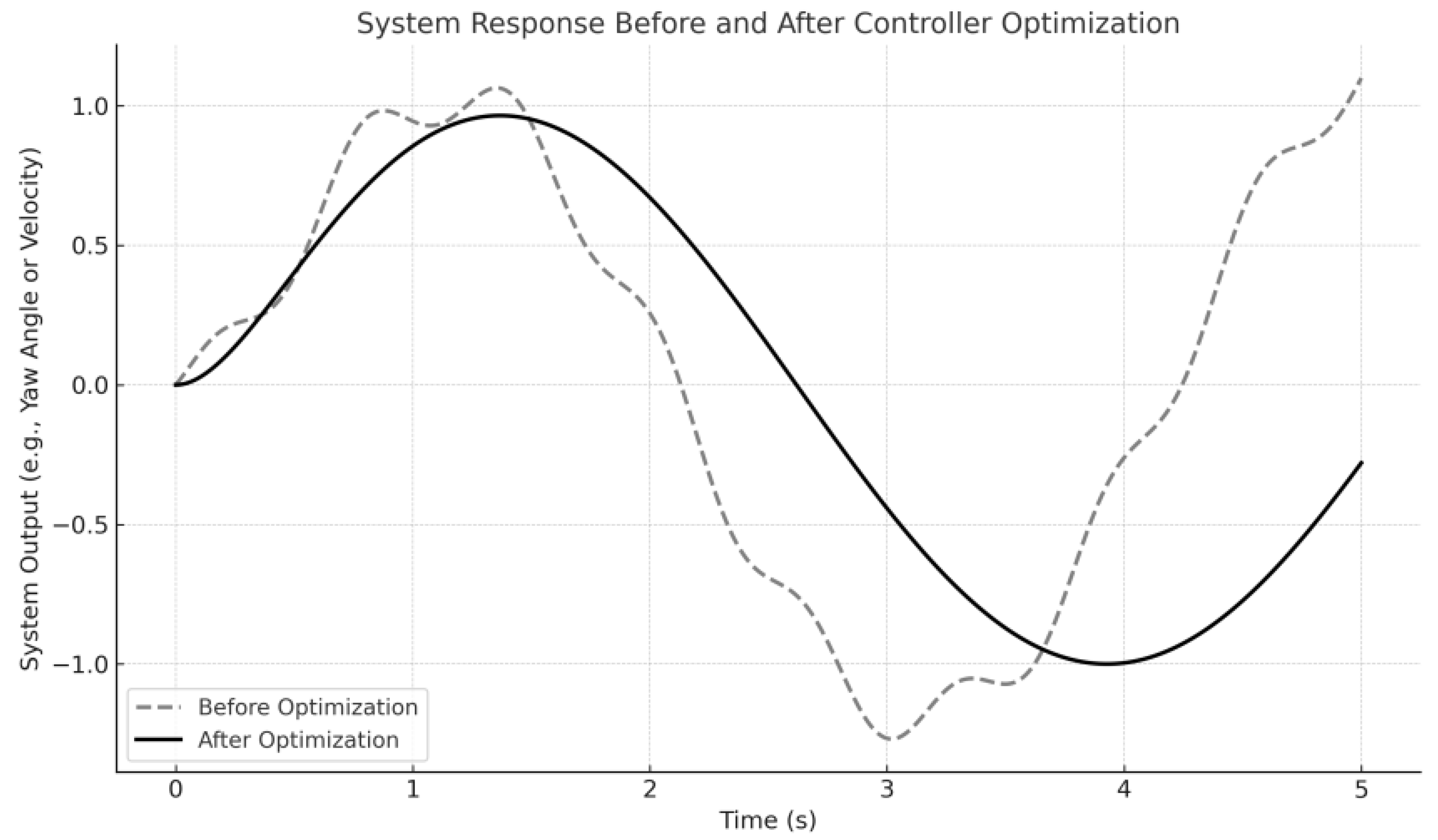
After the initial gain tuning, the fuzzy PD controller was further optimized in MuJoCo 2.3.7 under different terrains and operating conditions to improve dynamic performance. The optimized parameters were selected by comparing time-domain responses and choosing those that improved rise time, settling time, and overshoot while reducing control effort. Unless otherwise stated, the optimized parameters were used for all terrains and test cases to enable fair comparison.
Figure 8 compares the system responses before and after fuzzy PD controller optimization.
4.3. Control Architecture
The spherical robot achieves linear rolling and directional turning through two mechanically independent subsystems: a pendulum drive system and a gear rack turning mechanism. Although structurally decoupled, these subsystems are dynamically coupled through shared torques acting on the shell and internal frame, necessitating coordinated control to ensure stable and precise motion.
Each subsystem is regulated by an independent fuzzy PD inverse dynamics controller. The pendulum controller regulates the pendulum angle to generate forward motion, and the turning controller minimizes yaw error based on orientation feedback from the IMU. Effective integration of these control loops is essential for accurate trajectory tracking, in-place turning, and smooth transitions during complex maneuvers.
To coordinate the two subsystems, three strategies are implemented. First, the pendulum and turning controllers share sensor feedback to maintain consistent state estimation. Second, fuzzy PD gains are adaptively scheduled according to the motion phase, applying lower gains to maintain stability during rolling and higher gains to accelerate convergence during turning. Third, the output torque is adjusted through damping to reduce interference, such as suppressing turning torque during pendulum swings.
The control architecture supports two execution modes. In sequential execution, the pendulum is stabilized before initiating a turn, which is suitable for high-precision maneuvers. In simultaneous execution, both controllers operate concurrently, allowing heading corrections during rolling and enabling smooth curved trajectories with rapid directional adjustments. In both cases, synchronized control ensures that the subsystems reinforce rather than interfere with one another.
This integrated control architecture enables the robot to maintain continuous rolling, achieve accurate turning, and transition seamlessly between modes. By harmonizing two independently tuned fuzzy PD inverse dynamics loops, the system realizes adaptive, robust, and precise motion control across diverse terrains and operating conditions, providing a foundation for advanced trajectory planning and autonomous navigation.
5. Simulation and Experiment
This section presents simulation and experimental evaluations of the proposed mechanically decoupled spherical robot, which integrates pendulum-driven rolling and circular gear-rack turning. MuJoCo simulations and prototype tests were conducted under representative operating conditions to assess rolling performance, turning capability, and terrain adaptability.
5.1. Simulation Framework and Performance Evaluations
All simulations were performed in MuJoCo using forward dynamics with contact interactions. The evaluated scenarios included open-loop rolling, closed-loop speed regulation, in-place turning, and representative combined maneuvers. The simulation time step was set to
s, with the outer-loop controller running at
Hz. Key variables, including pendulum angle (
), shell angular velocity (
), control torque (
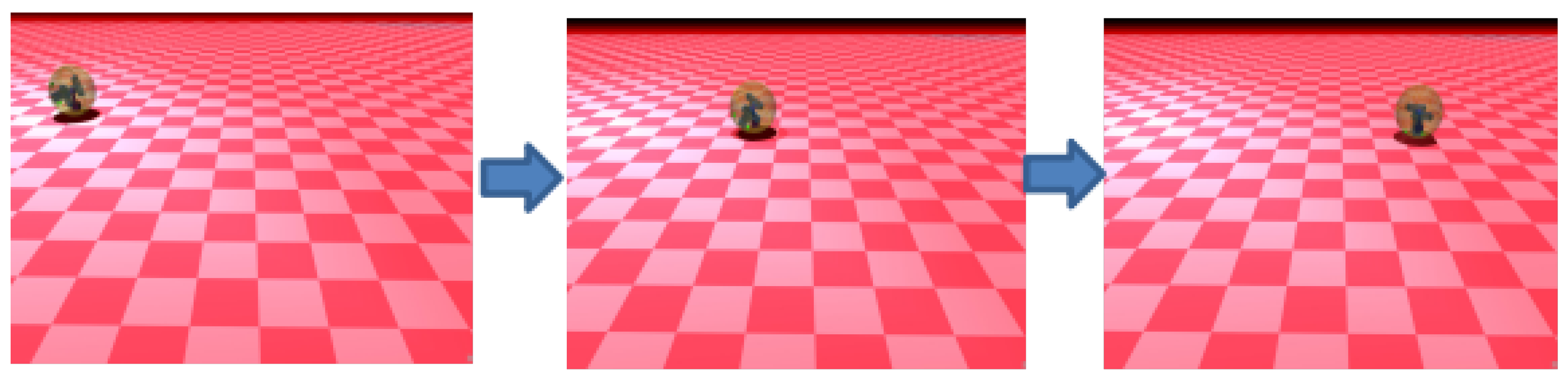
T), and tracking error, were logged for analysis and comparison with prototype experiments. Representative frames from the MuJoCo simulation environment are shown in
Figure 9.
Surface interaction was modeled using Coulomb friction, and the assigned static friction coefficient (
) for each surface is listed in
Table 2. For uneven-terrain tests, a height-field surface with a resolution of
and a maximum height amplitude of 10 mm were used to represent mild ground unevenness. Unless otherwise noted, all trials started from rest with
and lasted 12 s.
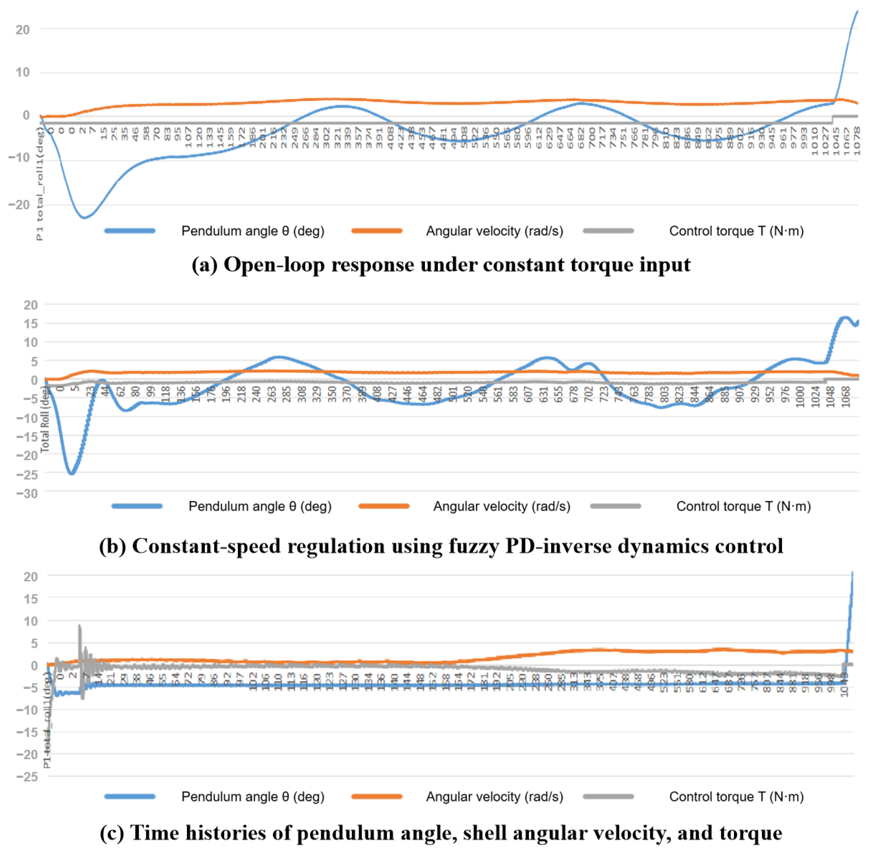
Under a constant open-loop torque input of 1.5 N·m, the robot transitions from rest to a steady rolling state. The shell angular velocity increases and converges to approximately 3 rad/s, while the pendulum angle remains bounded owing to the inertial and gravitational coupling between the internal pendulum and the outer shell (
Figure 10a).
In the speed-regulation case, the fuzzy inference system adaptively updates
and
according to the magnitude and rate of the velocity error, thereby enabling stable constant-speed rolling with limited overshoot and reduced oscillation (
Figure 10b). After convergence, the steady-state speed fluctuation remains within a narrow range, approximately
rad/s in the present simulations.
During forward rolling, the controller maintains the prescribed pendulum lead angle with only a small steady-state deviation while keeping the shell angular velocity synchronized with the reference motion. As the response settles, the required control torque gradually decreases toward a nearly constant level, indicating reduced control effort during steady operation and a smooth deceleration behavior (
Figure 10c).
In addition to the rolling cases, further simulation trials were carried out for in-place turning and representative combined maneuvers within the same MuJoCo framework. In the turning tests, the robot was commanded to execute reversible yaw maneuvers under closed-loop control, and the response exhibited stable convergence to the target heading without noticeable destabilization of the pendulum subsystem. Uneven-terrain simulations based on the height-field surface further suggest that the controller can preserve stable locomotion under time-varying contact disturbances by adaptively modulating the control torque in response to the tracking error. Overall, these results support the feasibility of the mechanically decoupled rolling and turning design and provide a simulation baseline for the subsequent prototype experiments.
5.2. Surface Interaction Analysis
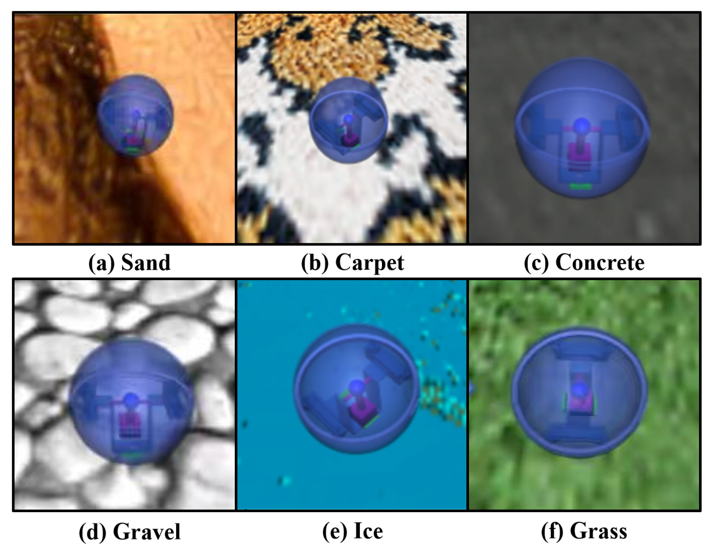
This subsection examines the influence of different simulated surface conditions on the rolling and turning performance of the spherical robot under the fuzzy PD–inverse dynamics controller. Representative surfaces considered in the simulation study include concrete, carpet, grass, sand, gravel, and ice, as illustrated in
Figure 11.
In the rolling simulations, rigid surfaces such as concrete resulted in smaller pendulum oscillations and more stable shell-velocity behavior. Carpet and grass also supported stable rolling, although larger oscillations and more noticeable torque modulation were observed. Sand and gravel remained traversable in simulation, but the controller required more frequent compensatory adjustment to maintain stable motion. Ice presented the most challenging rolling condition, as the low-friction surface tended to increase rolling speed and made the system more prone to instability.
In the turning simulations, concrete exhibited smooth yaw response with minimal overshoot. Carpet and grass remained controllable, with adaptive torque modulation supporting stable turning behavior. Sand and gravel showed larger delay or fluctuation during yaw regulation, whereas ice remained turnable but with increased sensitivity to slippage.
Overall, the simulation results indicate that the controller performs more reliably on rigid and medium-friction surfaces, whereas low-friction or more challenging surface conditions require more frequent compensatory adjustment. These observations support the adaptability of the proposed control strategy under different simulated surface conditions.
5.3. Turning Tests on Representative Terrains
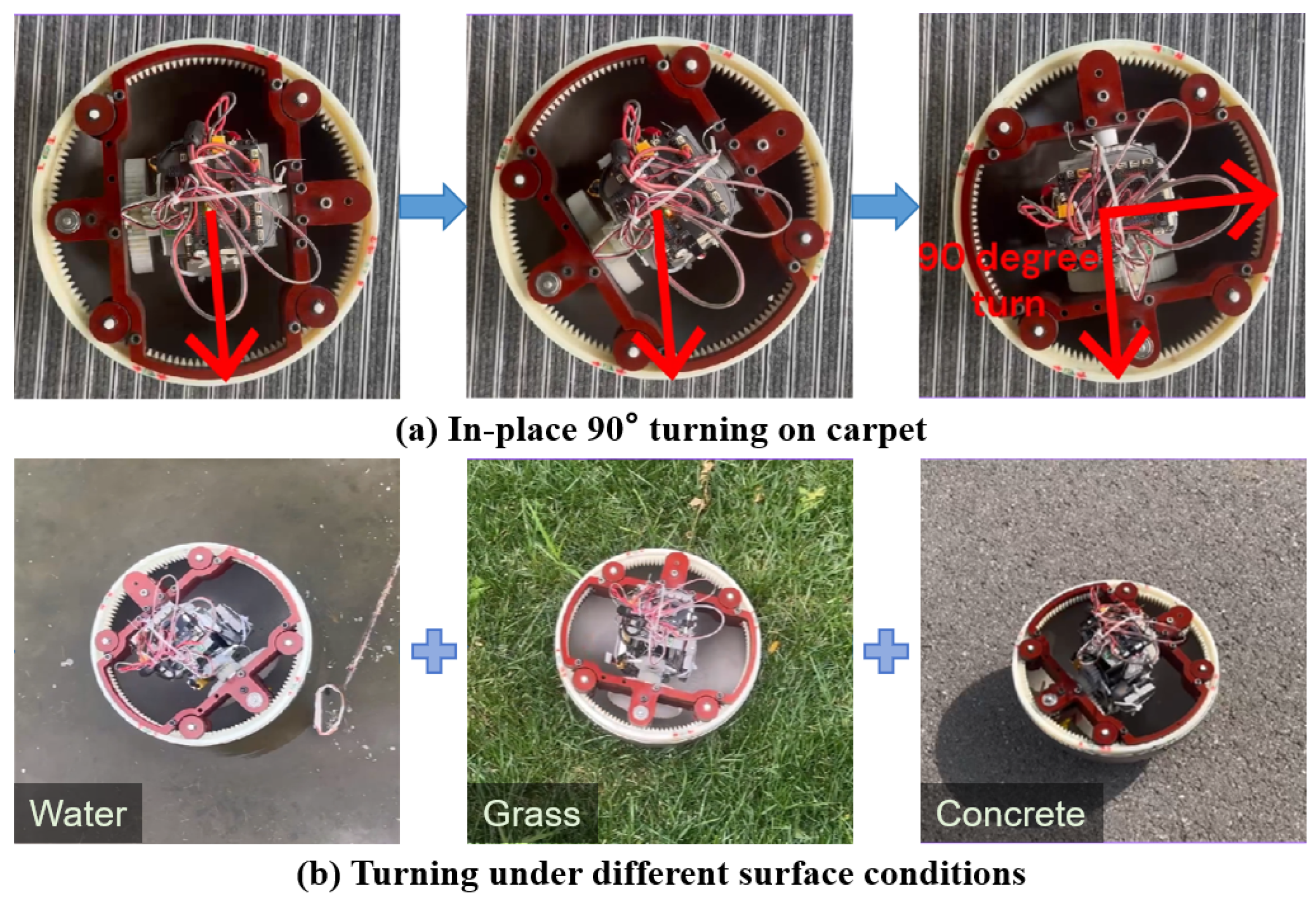
To validate the turning mechanism and control strategy on the prototype, in-place turning experiments were conducted under several representative surface conditions, including concrete, carpet, grass, and water, as shown in
Figure 12. In each case, the robot was commanded to execute an in-place yaw maneuver from
to
. For each surface condition, at least five repeated trials were performed, and the results shown here correspond to typical trials with qualitatively consistent turning behavior.
On concrete, the robot achieved stable turning with precise yaw regulation and no noticeable slip. On carpet, the turn remained smooth but was more gradual than on the rigid surface, reflecting the effect of surface compliance and friction variation. On grass, reduced traction and responsiveness led to slower turning behavior, but the controller maintained bounded deviation and overall stability throughout the maneuver. In the water test, the robot also completed the turn, indicating that the proposed turning mechanism remained functional under increased drag and reduced traction conditions.
These experimental observations indicate that the proposed turning mechanism can achieve reliable in-place yaw control under representative test conditions, while the surface condition primarily influences the transient smoothness and responsiveness of the turning process rather than the basic feasibility of the maneuver.
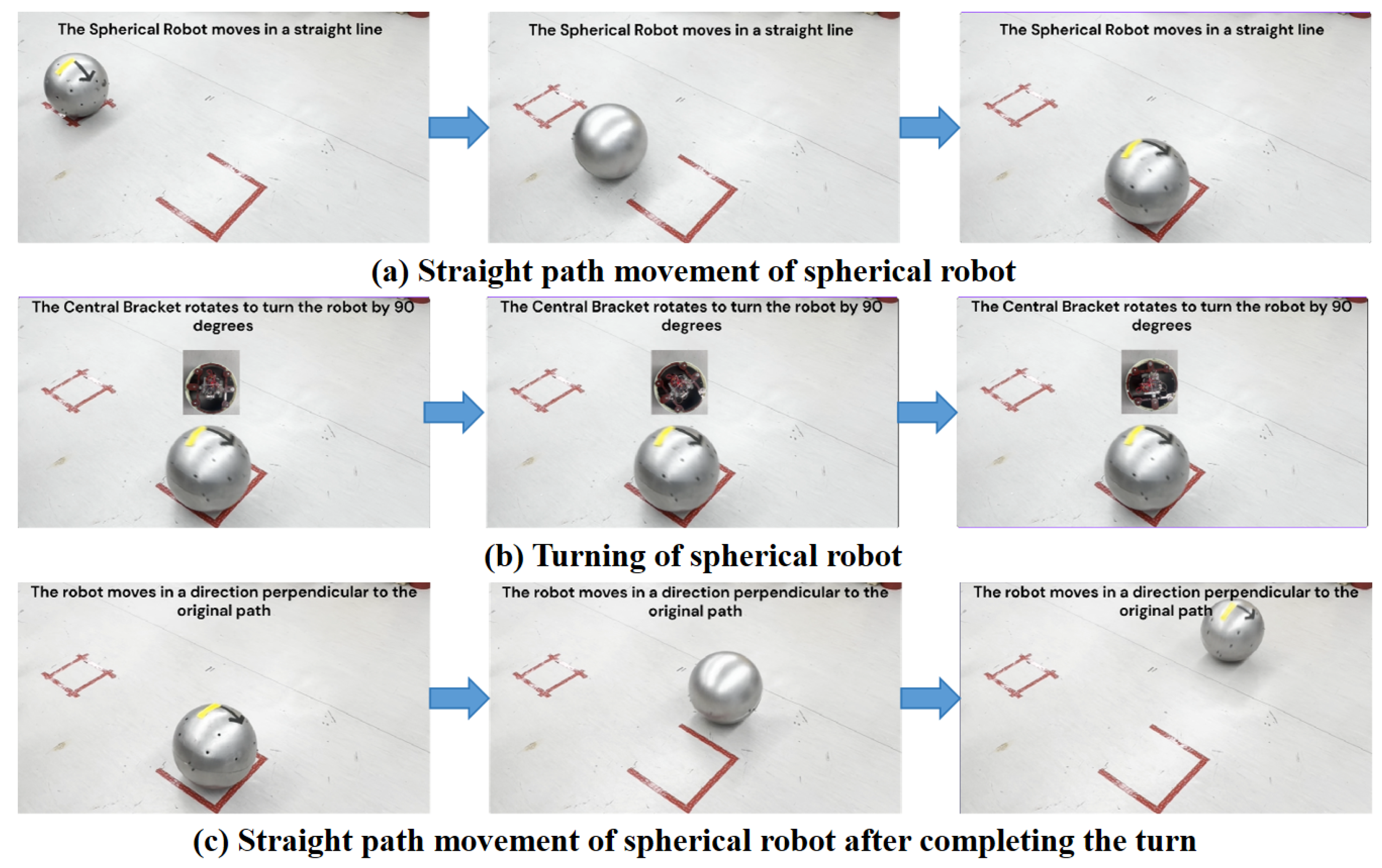
5.4. Straight-Path Rolling and In-Place 90° Turn Experiment
In this experiment, the spherical robot was commanded to follow a predefined straight path, execute an in-place
turn at the waypoint, and then continue rolling in the new direction over the same planned distance. This test was used to evaluate the coordination between the rolling and turning subsystems in a basic navigation task. The experiment was repeated at least five times under the same setup, and the sequence shown in
Figure 13 and
Supplementary Video S1 corresponds to a representative trial with consistent overall behavior across repeated runs.
During the initial straight-path phase (
Figure 13a), the robot maintained stable motion and remained aligned with the intended direction. At the turning point (
Figure 13b), it completed the in-place
maneuver smoothly with limited lateral displacement, indicating effective coordination between the rolling and turning mechanisms. After reorientation (
Figure 13c), the robot continued along the new heading over the planned path segment. Across the recorded trials, the robot remained close to the intended path and heading throughout the maneuver, demonstrating the ability of the proposed system to coordinate straight rolling and in-place turning in a basic navigation task.
5.5. Discussion
The simulation and prototype results indicate that the proposed mechanically decoupled architecture improves the maneuverability of pendulum-driven spherical robots without sacrificing the structural compactness and energy-efficiency advantages of pendulum-based rolling. Conventional pendulum-driven spherical robots are attractive because of their simple enclosed structure and efficient rolling mechanism, but their turning agility is often limited because steering is commonly achieved through center-of-mass shift under nonholonomic rolling constraints [
11,
14]. In the present design, the circular gear-rack turning mechanism introduces a dedicated yaw actuation path, so that heading regulation no longer depends exclusively on pendulum-induced steering. The main significance of this mechanism is that it realizes a functional separation of propulsion and steering at the mechanical level, thereby improving turning flexibility, especially for in-place reorientation. This design concept is also consistent with previous efforts toward decoupled dynamics control in spherical robot navigation [
12].
Another important implication is that the decoupled architecture makes the control problem more structured. Rolling and turning are implemented by two functionally different subsystems and regulated by separate control loops. This does not mean that the two motions are completely independent in dynamics, because both subsystems still interact through the shell and body motion. However, compared with conventional pendulum-steered designs, the present structure reduces the strong functional coupling between forward rolling and heading adjustment, making controller organization and tuning more straightforward. The stable rolling behavior and repeatable heading adjustment observed in both simulation and prototype experiments support the practicality of this design for basic locomotion and turning tasks.
The terrain-related results further clarify the applicability and limits of the platform. The robot remained operable across several representative surface conditions, suggesting that the proposed design can tolerate moderate variation in ground-contact conditions, especially friction-related differences. At the same time, low-friction or deformable surfaces make turning transitions more difficult because slip tendency increases and motion consistency decreases. Therefore, the proposed design should be understood as a mechanism that alleviates rolling–turning coupling and improves maneuverability, rather than a complete solution to terrain-dependent performance degradation. These observations are broadly consistent with previous studies on spherical robot ground interaction and motion constraints [
8].
Several limitations should also be noted. First, the MuJoCo-based simulation framework provides a useful validation environment, but its contact modeling remains simplified and cannot fully reproduce deformable terrain, local sinkage, or detailed contact behavior. Second, although the prototype experiments demonstrate representative rolling and turning maneuvers, the present study still focuses on validation of the proposed concept rather than a full statistical benchmark against other spherical robot architectures. Third, the current paper does not yet provide a unified quantitative comparison using metrics such as turning error, settling time, path deviation, or energy consumption. Future work should therefore focus on improving contact-model fidelity, expanding repeated-trial quantitative evaluation, and establishing clearer comparative benchmarks for different spherical robot actuation schemes.
6. Conclusions
This work presents a pendulum-driven unmanned spherical robot with a mechanically decoupled rolling and turning architecture. By integrating a circular gear-rack turning mechanism with a fuzzy PD control strategy, the proposed system achieves stable rolling and direct yaw control in a compact internal structure, thereby improving maneuverability over conventional pendulum-driven steering concepts.
Simulation and prototype results show that the robot can perform straight rolling and in-place reorientation under representative surface conditions, supporting the practicality of combining pendulum-driven locomotion with a mechanically decoupled turning mechanism in a spherical robot platform.
Future work will focus on improving contact-model fidelity, expanding quantitative performance evaluation, optimizing mechanical parameters, and advancing miniaturization for more practical outdoor deployment.