Abstract
This paper addresses the cruise range maximization problem for hypersonic drones by proposing a combined aerodynamic force/thrust vector trajectory optimization method. A novel continuous linear parameterization strategy for trajectory optimization is innovatively developed, achieving continuous thrust vector trajectory optimization throughout the entire flight using only 21 parameters through recursive linear function design. This approach reduces parameter dimensionality and effectively addresses sparse rewards and training difficulties in reinforcement learning. The study integrates the Deep Deterministic Policy Gradient (DDPG) algorithm with deep residual networks for trajectory optimization, systematically exploring the impact mechanisms of different aerodynamic force and thrust vector combination modes on range performance. Through collaborative trajectory optimization of thrust vectors and flight height, simulation results demonstrate that the combined trajectory optimization strategy achieves a total range enhancement of approximately 146.14 km compared to pure aerodynamic control, with continuous linearly parameterized thrust vector trajectory optimization providing superior performance over traditional segmented methods. These results verify the significant advantages of the proposed trajectory optimization approach and the effectiveness of the deep reinforcement learning framework.
1. Introduction
Hypersonic drones, with their advantages of high speed, long-range capability, and rapid response [1], have become the core development direction for aerospace integrated platforms [2]. When executing complex missions, the cruise range performance serves as a critical indicator for evaluating the comprehensive operational effectiveness of these drones [3]. Currently, mainstream cruise trajectory optimization methods primarily rely on aerodynamic control strategies, which adjust flight paths by modifying parameters such as angle of attack or pitch angle to achieve range maximization [4]. However, at high Mach numbers, traditional aerodynamic control methods face challenges including reduced control efficiency [5], high energy consumption [6], and shrinking flight envelope boundaries [7], making them inadequate for high-performance control requirements in complex environments.
For hypersonic drones, thrust vector control serves as an enhanced control mechanism that can provide additional control moments by dynamically adjusting the direction of engine exhaust flow [8], thereby achieving coupled control of both attitude and trajectory. This approach significantly enhances the longitudinal and lateral coupled control capabilities of the drone. Numerous researchers have analyzed the impact of thrust vector control on drone maneuverability and validated the advantages of thrust vectoring in maneuvering control capabilities [9,10,11]. Kondo et al. [12] demonstrated the feasibility of in-flight thrust vector observation for micro-UAVs using force feedback control. Perez et al. [13] developed an add-on thrust vectoring system for torsional work applications, enabling omnidirectional force generation independent from multirotor propellers. Although the concept of thrust vector control has achieved preliminary applications in attitude stabilization for certain drones, these studies primarily focus on attitude control and maneuvering performance, with limited involvement in combined optimization with aerodynamic control. How to achieve collaborative planning between thrust vectors and flight trajectories still faces challenges, including complex modeling, high-dimensional control variables, and strong coupling relationships.
In trajectory optimization, existing research primarily employs optimal control methods or intelligent optimization algorithms, such as gradient methods, pseudo-spectral methods, sequential quadratic programming, particle swarm optimization, and genetic algorithms. Liu et al. [14] developed a robust control method for hypersonic unmanned flight vehicles based on model predictive control, addressing trajectory tracking under complex constraints and demonstrating the effectiveness of predictive control approaches in hypersonic vehicle trajectory optimization. Wang et al. [15] presented an intelligent trajectory prediction algorithm for hypersonic glide vehicles based on sparse associative structure models, showing significant improvements in trajectory forecasting accuracy for defense applications. Mahmood et al. [16] applied control vector parameterization to trajectory optimization of subsonic unpowered gliding vehicles, demonstrating the effectiveness of parameterization approaches in reducing computational complexity. Recent studies in the Drones journal have extensively explored optimization algorithms for UAV applications. Srivastava et al. [17] developed PSO-based approaches for route optimization in precision agriculture UAV applications. Zhang et al. [18] proposed UAV formation trajectory planning algorithms, providing systematic reviews of genetic algorithms and particle swarm optimization techniques for collaborative UAV operations. Yang et al. [19] presented a comprehensive bibliometric analysis of UAV path planning trends from 2000 to 2024, highlighting the evolution from traditional algorithms to intelligent optimization methods. Labbadi et al. [20] reviewed path planning challenges and future directions for autonomous drones, emphasizing the importance of advanced trajectory optimization techniques in complex environments. Furthermore, recent advances have focused on real-time trajectory planning solutions. Bigazzi et al. [21] proposed suboptimal trajectory planning techniques for real UAV scenarios with partial knowledge of the environment, while Rodriguez et al. [22] developed computer vision-based path planning approaches for low-cost autonomous drones. These studies provide optimization methods for solving trajectory optimization problems. While these methods perform well when handling low-dimensional, static constraint problems, they often encounter local optima due to the curse of dimensionality and function discontinuities in high-dimensional, dynamic, nonlinear systems, making them difficult to extend to collaborative thrust vector and trajectory optimization problems. Additionally, such algorithms typically rely on fixed control parameter forms or piecewise modeling approaches, lacking continuous and differentiable control strategy representation capabilities, which limits further improvements in control precision.
Recent advances in deep learning have significantly expanded the theoretical foundations for complex system modeling and optimization. Topological data analysis methods, such as persistent homology [23], have enhanced our understanding of high-dimensional data structure representation, while hierarchical network architectures [24] have demonstrated improved feature extraction capabilities in complex scenarios. Building upon these theoretical advances, the rapid development of deep reinforcement learning technology has provided new solutions for high-complexity flight control problems. Based on the “state-action-reward” interactive learning mechanism, it possesses end-to-end policy learning capabilities and can directly extract optimal control strategies from flight environments. Liu et al. [25] developed a deep reinforcement learning-based 3D trajectory planning method for cellular-connected UAVs, demonstrating the effectiveness of DRL in complex trajectory optimization scenarios. Recent Drones journal publications have extensively explored DRL applications in UAV autonomous navigation. Yang et al. [26] proposed a new autonomous method for drone path planning based on multiple strategies for avoiding high-speed and high-density obstacles. Wang et al. [27] developed UAV autonomous navigation algorithms using deep reinforcement learning in highly dynamic environments. Wang et al. [28] presented vision-based deep reinforcement learning approaches for UAV autonomous navigation using privileged information. Savkin et al. [29] provided comprehensive strategies for optimized UAV surveillance in various tasks and scenarios, highlighting the integration of AI technologies with UAV operations. Azar et al. [30] provided a comprehensive review of deep reinforcement learning applications in drone systems, highlighting the growing importance of DRL techniques for autonomous UAV operations and trajectory optimization problems. Although deep reinforcement learning demonstrates broad application prospects in flight control, introducing it to hypersonic drone trajectory optimization still faces three key challenges: first, slow training convergence and unstable policies in high-dimensional action spaces; second, complex reward function design that easily leads to policy convergence to local optima; and third, predominantly shallow network architectures that struggle to characterize the strongly coupled, highly nonlinear dynamic behaviors of the system.
Based on the aforementioned challenges, this paper addresses the trajectory optimization requirements for hypersonic drones during the cruise phase by proposing a combined trajectory optimization strategy that integrates deep reinforcement learning with innovative parameterization methods. A novel continuous linear parameterization approach for thrust vector trajectory optimization is innovatively developed, using only 21 parameters to describe the complete thrust angle variation process throughout the entire flight segment through recursive linear function design. This breakthrough significantly reduces control dimensionality while effectively addressing sparse rewards and training difficulties inherent in reinforcement learning. The study develops three progressively complex trajectory optimization schemes: baseline trajectory optimization using traditional particle swarm optimization with fixed thrust vector angles and height parameters, continuous linear parameterized trajectory optimization that introduces deep residual networks to enhance policy representation capability, and collaborative trajectory optimization that achieves joint optimization of flight height and thrust angles through an improved DDPG algorithm within an end-to-end framework.
2. Problem Formula
A modified hypersonic drone model from Zhou & Huang [31] is employed in the present research. As shown in Figure 1, this drone features a full-waverider configuration with a length of 7.4 m, a planform area of 14 m2, and a wingspan of 3.5 m. RP-3 aviation kerosene serves as the fuel, with a total mass of approximately 3.45 t when fully fueled and a fuel load of around 1.5 t. The engine’s thrust varies between approximately 7.7 kN and 10.05 kN across different flight conditions.
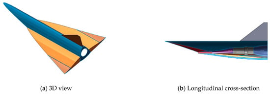
Figure 1.
Geometric model of hypersonic drone.
To comprehensively describe this drone, accurate models for dynamics, aerodynamics, and propulsion are essential. For the aerodynamic modeling, this study directly adopts the validated aerodynamic data from Zhou & Huang, whose research conducted detailed CFD calculations using coupled RANS equations, the SST k-ω turbulence model, and Sutherland’s law on a computational mesh of 13.97 million cells. Their work thoroughly validated the hypersonic flow physics, including shock wave capture, boundary layer separation, and aerodynamic heating effects, providing a reliable foundation for the present trajectory optimization study.
While Mach-6 flow may involve high-temperature real gas phenomena such as molecular dissociation, ionization, and vibrational excitation, the present study focuses on flight-control trajectory optimization rather than detailed aerothermodynamic prediction. The aerodynamic database adopted from Zhou & Huang was generated using validated CFD under a perfect gas assumption. For the altitudes and slender body configuration considered here, previous comparisons show that real gas corrections exert a much stronger influence on thermal loads than on the integrated aerodynamic force and moment coefficients that drive the vehicle’s global motion. Consequently, the simplified perfect gas coefficients are adequate for evaluating the guidance and control strategy.
2.1. Aerodynamic Model
The drone model is used as the research object. The aerodynamic model is established based on the aerodynamic data obtained from the force and moment balance state in the article. The thrust model is established based on the air flow data obtained from the thrust gain and specific fuel consumption data in the article.
The aerodynamic model is
The thrust model is
Herein is the aerodynamic force, represents the aerodynamic coefficient, denotes the dynamic pressure of the flight, is the angle of attack, is the height, is the thrust gain specific impulse and is the reference area of the drone, which is defined as the horizontal projection area of the drone. denotes the thrust, is the equivalence ratio, is the stoichiometric ratio of kerosene, and is the airflow captured by the inlet.
2.2. Dynamic Model
Assuming the Earth is a two-axis rotating ellipsoid, the spatial trajectory equations are established in the ground-launched coordinate system. The equations of motion for the center of mass are given by Equation (3):
where represents the mass of the drone, is the control force (the control force is calculated based on the aerodynamic database from Zhou & Huang [31], where control effectiveness derivatives are obtained through interpolation for different flight states. In this study, an instantaneous response assumption is adopted for the control surfaces, assuming negligible actuator dynamics compared to the vehicle dynamics timescale), is the additional Coriolis force, is the angular velocity of the ground-launched coordinate system relative to the inertial coordinate system. The term represents the Coriolis inertial force, and represents the centrifugal inertial force. is the velocity of the drone relative to the launch coordinate system, is the acceleration of the drone in the launch coordinate system, and is the position vector of the drone in the inertial coordinate system.
For the thrust vector optimization of quasi-steady cruise considered here, the height and velocity remain nearly constant, but the trajectory inclination angle varies continuously to maintain constant geodetic altitude over the curved Earth. Under this condition, the governing equations:
Here, is the velocity of the drone, is the trajectory inclination angle, is the drag, is the lift, is the mass of the drone, is the acceleration due to gravity. is the thrust vector deflection angle, and it is defined as positive when the thrust vector is deflected downward. As shown in Figure 2.
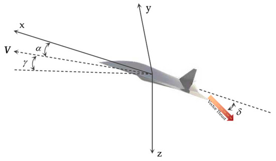
Figure 2.
Thrust vector deflection angle.
Equation (3) presents the full equations of motion of the vehicle’s center of mass in the ground-launched rotating reference frame. Although an ideal steady-state cruise satisfies the force balance , which implies zero net acceleration, the equation remains essential and non-trivial in several respects.
Transient dynamics: During maneuvers—such as adjustments of thrust vector angle δ or altitude—the vehicle experiences non-zero accelerations, and Equation (3) governs the corresponding dynamic response.
Trajectory optimization: The optimization procedure explores candidate trajectories that may depart from equilibrium. The full dynamic equation provides the necessary constraints to guarantee that optimized solutions are physically realizable.
Geometric effects: Even during “steady” cruise at approximately constant altitude and speed, the trajectory inclination angle varies slightly to compensate for Earth’s curvature, so the system is never in perfect equilibrium.
These considerations highlight that Equation (3) serves as the general dynamic foundation for both the transient phases and the steady-cruise analysis.
3. Optimization Method and Theoretical Analysis
3.1. Optimization Problem of Cruise
Research Scope and Flight Assumptions: This study focuses exclusively on steady-state cruise trajectory optimization for hypersonic drones. All analyses assume a constant cruise velocity of Mach 6 throughout the entire flight segment, representing typical hypersonic cruise operational conditions. The research scope does not encompass acceleration phases from takeoff to cruise speed or deceleration during descent, as these transient phases involve fundamentally different optimization objectives and dynamic constraints. This constant velocity assumption enables focused investigation of the aerodynamic force/thrust vector collaborative optimization effects on cruise range performance while eliminating the computational complexities associated with variable speed profiles.
Trajectory optimization is actually an optimal control problem. In this problem, optimal control variables are searched for to make one of the performance parameters best for a control system. Generally speaking, a standard optimal control problem is described as follows.
The state equations are:
The optimization objective is to maximize the flight range of the drone, which is:
The range of values for delta was determined by referring to Gu & Xu [32,33]. The limits of h are determined according to the original data benchmark. Therefore, the optimization problem of cruise trajectory can be formulated as Equation (7).
3.2. Particle Swarm Optimization (PSO)
In the fixed thrust vector angle steady-state cruise optimization, since the optimization variables are constant cruise height and thrust vector deflection angles, this approach has been proven suitable for low-dimensional optimization problems [34] and provides intuitive programming for handling optimization tasks.
The optimization process is illustrated in Figure 3, which shows the overall flow from generating the initial population randomly through calculating fitness values and checking termination conditions.
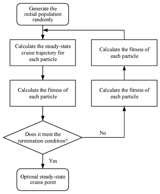
Figure 3.
Optimization process for the optimal steady-state cruise point.
The following presents the fundamental principles of the Particle Swarm Optimization (PSO) algorithm. There are N particles in the swarm. The position of the i-th particle is xi, and its velocity is vi. The best position experienced by the i-th particle is represented as pi, while the best position experienced by the entire swarm is denoted as pg. Based on these definitions, the algorithm flow of the PSO is described as follows:
Step 1: Initialize the swarm, including the number of particles. Randomly generate the positions and velocities of each particle.
Step 2: Calculate the fitness value of each particle using Equation (10), which represents the total flight distance achieved by the corresponding trajectory parameters.
Step 3: For each particle i (i = 1, 2, 3, …, N), compare its current fitness value with its personal best position pi (the best position that particle i has experienced during the search process). If the current position yields better fitness according to Equation (10), update pi to the current position. Additionally, compare the current fitness value with the global best position pg (the best position found by the entire swarm). If a better position is found, update pg to this new position.
Step 4: Update the position xi and velocity vi of each particle based on the current global best pg and the individual best pi. The update formulas are as follows:
Here, k denotes the iteration number of the particles. c1 and c2 are learning factors, typically set as positive constants. The functions rand () and Rand () represent random numbers between (0, 1), and w is the inertia weight.
Step 5: If the termination condition is met (either reaching the maximum number of iterations or satisfying the optimal solution condition), the algorithm terminates. Otherwise, return to Step 2 and continue the calculations.
Optimizing for maximum range, the variables are the thrust vector angle and cruise height, with the fitness function as defined in Equation (8):
The optimal position can be obtained from Equation (11), and the global optimal point can be obtained from Equation (12):
3.3. PSO Algorithm Parameter Sensitivity Analysis
The experiments in this paper are based on the drone model from, to verify the robustness and convergence characteristics of the PSO algorithm in this problem, this paper conducts sensitivity analysis on key parameters. First is the analysis of inertia weight influence. The inertia weight w controls the degree to which particles maintain their current motion direction. By comparing the performance of different inertia weight strategies, it is found that high inertia weight provides strong global search capability but slow convergence, while low inertia weight offers strong local search capability but is prone to falling into local optima. Therefore, this paper adopts a strategy where w decreases linearly from 0.9 to 0.4. Experimental results demonstrate that the linear decreasing strategy achieves optimal balance between convergence speed and solution quality.
A dynamic adjustment strategy for learning factors is also employed. In this study, the initial individual learning factor is set to 3.0, and the initial social learning factor is set to 0.5. As the number of iterations increases, the individual learning factor gradually decreases while the social learning factor gradually increases. Specifically, the individual learning factor decreases from 3.0 to 0.5, and the social learning factor increases from 0.5 to 3.0. The purpose of this setting is to allow particles to rely more on their own experience for exploration in the early stages of iteration, and to depend more on the collective intelligence of the swarm for exploitation in later stages. This method helps balance the functions of global search and local search.
3.4. Deep Reinforcement Learning Optimization Method Based on Continuous Linear Parameterization
3.4.1. Continuous Linear Parameterization Control Strategy
To address the contradiction between control precision and training efficiency in traditional piecewise control methods, this paper proposes a continuous linear parameterization control strategy. The core concept of this strategy is to describe the time-varying characteristics of control variables during flight through linear functions, achieving continuous control throughout the entire process with a finite number of parameters, thereby significantly reducing the optimization problem dimensionality while ensuring control precision. Traditional piecewise control methods require separate control parameters for each discrete segment, resulting in excessively high parameter dimensionality and discontinuous control. In contrast, the continuous linear parameterization method employs a recursive design with natural transitions between segments, enabling the description of continuous control trajectories throughout the entire flight process using minimal parameters.
For thrust vector angle control, the continuous linear parameterization is expressed as:
where represents the thrust vector angle change rate for the i-th segment, is the initial thrust vector angle, and is the time duration of the j-th segment. This representation method ensures the continuity of thrust vector angles throughout the entire flight process while reducing optimization parameters from hundreds in traditional methods to 21 (20 change rate parameters + 1 initial value parameter).
For flight height control, a similar parameterization strategy is adopted:
where represents the height change rate for the i-th segment, and is the initial flight height.
3.4.2. DDPG Algorithm Integrated with Deep Residual Networks
Based on the continuous linear parameterization strategy, this paper designs a DDPG algorithm framework integrated with deep residual networks, which can adapt to optimization problems of different dimensions. Existing deep reinforcement learning methods primarily employ shallow network architectures (typically with only 2–3 hidden layers), resulting in limited representation capability when handling highly nonlinear, strongly coupled systems such as hypersonic drones, while also facing challenges including gradient vanishing and training instability. The algorithm incorporates a residual Actor network and a residual Critic network , which effectively alleviates the gradient vanishing problem in deep networks through residual connections, significantly enhancing network representation capability and training stability. Where represents the state, represents the action, and , are the network parameters, respectively. The core concept of residual connections is to allow information to propagate through direct skip connections, avoiding gradient vanishing phenomena in deep networks, thereby enabling the network to learn complex continuous control strategies throughout the entire process. The mathematical representation of residual connections is:
where represents the residual mapping function, and is the output of the l-th layer. The key advantage of residual connections lies in their improvement over gradient propagation. For residual connections, the gradient computation is:
where represents the unit distance. Due to the existence of identity mapping, even when , the gradient still has a lower bound , ensuring that gradients can effectively propagate to the front layers of the network, thereby solving the gradient vanishing problem in deep networks.
The algorithm employs a unified training framework to handle optimization problems of different modes, achieving algorithm generality and scalability through modular design. The training process is based on the Actor–Critic architecture, optimizing continuous control strategies through policy gradient methods while utilizing experience replay mechanisms to improve sample efficiency. Based on these definitions, the ResNet-DDPG algorithm is described as follows:
Step 1: Initialize residual network architecture. Construct a 7-layer residual Actor network including an input layer that receives state dimensions (current mass, current segment number, current thrust angle, intra-segment time ratio), hidden layers with a decreasing structure of 512→384→256→192→128→64 and residual connections between the 3rd and 5th layers, and an output layer producing 21 neurons (20 parameters + 1 parameter)/42 neurons (20 parameters + 1 parameter + 20 parameters + 1 parameter) using tanh activation function. Simultaneously construct a 9-layer residual Critic network including a state encoding path ss s→384→256→192, an action encoding path aa a→192→128, and a fusion path 384→320→256→192→128→64→1 with residual connections between the 3rd and 5th layers of the fusion path. Initialize network weights , set target networks and , and initialize experience replay buffer with capacity set to .
Step 2: Policy execution and environment interaction. For each episode , reset the environment and observe the initial state , initialize the Ornstein–Uhlenbeck noise process . For each time step , generate deterministic actions through the residual Actor network , add exploration noise to obtain actual execution actions , execute action and observe reward and next state , store the experience tuple in replay buffer .
Step 3: Network parameter update. When the replay buffer contains sufficient experience (|R| ≥ N), randomly sample a mini-batch of data from , compute target Q-values through the residual target network , update the residual Critic network by minimizing the loss function, and update the residual Actor network by maximizing the policy objective:
Step 4: Soft update of target networks. Perform soft updates to ensure target networks slowly track the main networks, where is the soft update parameter:
Step 5: Convergence criterion. If the termination condition is satisfied, including reaching the maximum number of episodes or the average reward change over consecutive 100 episodes is less than the threshold or the predetermined performance target is achieved, then stop training; otherwise, return to Step 2 to continue training.
3.4.3. Model Training Process and Parameter Configuration
To effectively train the proposed ResNet-DDPG controller for hypersonic cruise trajectory optimization, this paper designs a structured training process and reasonably configures key hyperparameters. The agent operates in a high-fidelity simulation environment, updating thrust deflection angle (or thrust deflection angle and flight height in real-time with a temporal resolution of 1 s to control the trajectory evolution of the drone.
At each time step , the agent observes the current state , where is the flight height, is the current mass, and is the current flight segment number. The policy network (Actor) generates action (or ) based on the state, which is then input into the real aerodynamic simulation function to compute the next state , current drone range . The transition tuple is stored in the experience replay buffer .
To encourage the agent to learn low fuel consumption cruise strategies, the reward function is designed as the unit time drone range rate, namely:
where
is range reward scaling coefficient, is the total range of the current strategy, is the range achieved under pure aerodynamic control with deployment at the planned height, is the thrust vector control smoothness penalty coefficient, and is the height variation constraint coefficient. The design of the reward function considers the primary objective of range maximization while balancing control smoothness and physical constraints. To ensure algorithm convergence and generalization capability, this study adopts the following hyperparameter configuration: as shown in Table 1.

Table 1.
Hyperparameter configuration.
4. Results and Analysis
The experiments in this paper are based on the drone model from [29], with the cruise speed of the drone set at Mach 6. The planned deployment height of the drone is 26 km. Initially, a comprehensive search for the maximum range of the drone was conducted within the thrust vector angle of 0° and the height range of 20 km to 30 km. Figure 4 shows the distance curves at all heights without TVC. As shown in the figure, the distribution of the range curves exhibits a parabolic shape with higher values in the middle and lower values on both sides. Both excessively high and low heights reduce the maximum range.
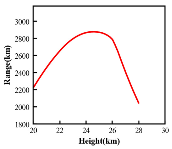
Figure 4.
Range for all heights under thrust vector angle of 0°.
The maximum range of a hypersonic drone during cruise can be calculated using the Breguet range formula. The Breguet range formula is given by:
where is the initial gross weight of the aircraft (including fuel), and is the final weight of the aircraft (after fuel consumption). For a given set of hypersonic drone parameters, there exists an optimal cruise point that maximizes the drone’s range. This optimal point is determined by the drone’s specific parameters, such as its aerodynamic efficiency (characterized by ), propulsion system performance (reflected in ), and fuel consumption characteristics (represented by the weight ratio ). Understanding how these parameters affect the optimal cruise point is crucial for drone design, as it provides insights into maximizing range and efficiency. Therefore, this section will analyze and compare the performance parameters of the hypersonic drone at steady-state cruise points under various control strategies.
4.1. Fixed Thrust Vector Control Results Analysis
4.1.1. PSO-Based Results Analysis
Within the search range, the maximum range of the drone reaches 2875.2 km, while the minimum is around 2000.3 km. The combination of thrust vector angle and height that yields the maximum range is identified as the optimal steady-state cruise point, denoted as (Deltaopt, Hopt), which is approximately located within the height range of 24 km to 26 km.
Based on the aforementioned PSO optimization procedure, optimization was performed to determine the optimal steady-state cruise point for the hypersonic drone model used in this study. The PSO algorithm parameters were configured as follows: swarm size was set to 30 particles with a maximum of 35 iterations. The inertia weight was maintained constant at 0.9 throughout the optimization process. The learning factors employed a dynamic adjustment strategy, where the self-learning factor (c1) decreased linearly from 3.0 to 0.5, while the group learning factor (c2) increased linearly from 0.5 to 2.0 over the iterations to balance exploration and exploitation capabilities. Velocity constraints were applied with maximum velocities of 200 m for altitude and 1° for thrust vector angle to ensure reasonable search steps. The optimization variables were bounded within feasible ranges: altitude h ∈ (20,000, 30,000) m and thrust vector angle δ ∈ (−32°, 32°). Figure 5 illustrates the evolution of the minimum fitness function value within the swarm across generations, showing that the algorithm converged after approximately 25 iterations. The optimized steady-state cruise point was found to have a height of 24.61 km and a thrust vector angle of 32°. The maximum range corresponding to the optimal steady-state cruise point was 2879.94 km. Compared to the strategy without thrust vector control (planned deployment height of 26 km), the range is improved by 95.04 km.
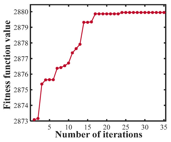
Figure 5.
The evolution process of optimal fitness.
4.1.2. Drone Parameter Analysis Under Fixed Thrust Vector Control
To verify the effectiveness of the proposed aerodynamic force/thrust vector combined trajectory optimization method, this section conducts a comprehensive performance comparison analysis between the fixed thrust vector trajectory optimization optimized by the PSO algorithm and the traditional non-thrust vector trajectory optimization. The thrust vector trajectory optimization employs the optimal flight height of 24.7 km and optimal thrust vector deflection angle of 32° obtained through the PSO algorithm optimization, while the traditional scheme uses the standard deployment height of 26 km.
As shown in Figure 6a, the 24.7 km flight height optimized by the PSO algorithm is 1.3 km lower than the standard 26 km deployment height of the traditional scheme, and both maintain stable height. The lower flight height places the drone in a more suitable atmospheric environment, increasing atmospheric density and creating favorable initial conditions for subsequent improvements in aerodynamic performance and propulsion system efficiency.
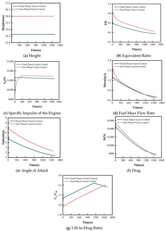
Figure 6.
Comparison of Drone Parameters Between Fixed Thrust Vector Control and Non-Thrust Vector Control.
As shown in Figure 6b, the equivalence ratio comparison demonstrates that the thrust vector trajectory optimization has significant combustion efficiency advantages. The equivalence ratio of the thrust vector trajectory optimization decreases smoothly from 0.7 to 0.4, while the traditional scheme decreases from a higher 0.85 to 0.45. The thrust vector trajectory optimization exhibits a lower initial equivalence ratio with a more gradual decline, indicating more complete combustion processes and more reasonable fuel-to-oxidizer mixing ratios, effectively reducing fuel waste.
As shown in Figure 6c, the specific impulse comparison results indicate that the thrust vector trajectory optimization achieves a specific impulse of approximately 11,300 s, slightly lower than the 11,500 s of the traditional scheme. Although the thrust vector control exhibits a minor disadvantage in specific impulse, it still provides a stable thrust output foundation for the propulsion system overall.
As shown in Figure 6d, the mass flow rate comparison demonstrates that the thrust vector trajectory optimization has significant fuel-saving advantages. Before 1200 s, the mass flow rate of the thrust vector trajectory optimization is notably lower. This indicates that the thrust vector trajectory optimization not only achieves the aforementioned combustion efficiency improvements but also effectively reduces the fuel consumption rate, further enhancing the drone’s range performance and demonstrating the significant advantages of this technical approach in terms of fuel economy.
As shown in Figure 6e, the angle of attack comparison demonstrates that the fixed thrust vector trajectory optimization possesses superior attitude control characteristics. The fixed thrust vector trajectory optimization’s angle of attack decreases smoothly from 5° to 1.5°, with a variation range of 3.5°, while the traditional scheme’s angle of attack decreases significantly from 7° to 3°, with a variation range of 4°. The smaller angle of attack variation range and more gradual change trend reduce drag fluctuations during flight, providing an important attitude control foundation for overall drag characteristic improvements.
The drag comparison analysis shown in Figure 6f reveals the significant aerodynamic advantages of the fixed thrust vector trajectory optimization. In the initial flight phase, the fixed thrust vector trajectory optimization’s drag is approximately 14,500 N, which is about 1000 N lower than the traditional scheme’s 15,500 N, representing a reduction of 6.5%. During the mid-cruise phase from 600 to 1200 s, the fixed thrust vector trajectory optimization consistently maintains lower drag levels. The drag advantage directly results from the comprehensive effects of the aforementioned optimized flight height and smooth angle of attack control.
As the core comprehensive indicator of drone aerodynamic performance, the lift-to-drag ratio concentratedly reflects the final effects of the aforementioned parameter optimizations. As shown in Figure 6g, the fixed thrust vector trajectory optimization achieves a lift-to-drag ratio higher than the traditional scheme for most of the time. The significant improvement in lift-to-drag ratio represents the comprehensive result of multi-factor synergistic effects, including flight height optimization, combustion efficiency improvement, smooth angle of attack control, and substantial drag reduction, fully validating the effectiveness of fixed thrust vector control technology in achieving aerodynamic performance enhancement through multi-dimensional parameter collaborative optimization.
4.2. Time-Varying Vector Control Results Analysis
4.2.1. DDPG Training Process Analysis
From the training curves as shown in Figure 7, the significant advantages of ResNet-DDPG over traditional DDPG can be clearly observed. In terms of final performance, ResNet-DDPG converges to approximately 10,000 reward level, while traditional DDPG only converges to about 6500, achieving a 46% performance improvement. This substantial difference directly validates the effectiveness of deep residual networks in continuous control tasks. Regarding convergence speed, ResNet-DDPG demonstrates faster learning efficiency, rapidly improving rewards from 5000 to 9000 in the first 1000 training episodes, then steadily converging to optimal levels during episodes 1000–2000, while traditional DDPG shows slow growth under the same training episodes and essentially stagnates after 1000 episodes. From the smoothness of the average reward curve, ResNet-DDPG exhibits ideal S-shaped growth characteristics with continuous gradient changes and no sudden jumps, while the traditional DDPG curve is relatively rough with obvious plateau phenomena. Training stability analysis indicates that ResNet-DDPG possesses better convergence characteristics. From the fluctuation range of Episode Reward, traditional DDPG exhibits large fluctuations throughout the entire process, showing significant instability even in later stages, indicating gradient vanishing or training difficulty problems. In contrast, ResNet-DDPG has some initial fluctuations but quickly stabilizes, with post-convergence fluctuation range controlled within ±50, and relatively low training noise.
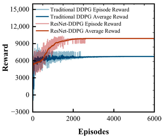
Figure 7.
Training Reward Curves of ResNet-DDPG and Traditional DDPG.
4.2.2. Drone Parameter Analysis Under Time-Varying Vector Control
Building upon the verification of the significant advantages of fixed thrust vector control over traditional non-thrust vector control, this section further explores the performance potential of time-varying thrust vector control. The time-varying thrust vector control employs a DDPG algorithm integrated with deep residual networks to achieve continuous linear parameterized adjustment of thrust vector angles. Compared to the single optimal angle of fixed thrust vector control, it can optimize thrust vector direction in real-time according to flight states, theoretically possessing greater potential for performance improvement. The range under time-varying thrust vector control is 5.7 km greater than that under fixed thrust vector control, and the thrust vector deflection angles of both are shown in Figure 8a.
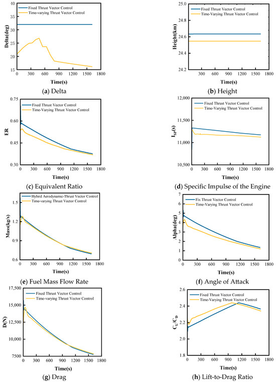
Figure 8.
Comparison of drone parameters between fixed thrust vector control and time-varying thrust vector control.
As shown in Figure 8b, the height comparison demonstrates that both trajectory optimization maintain similar flight height around 24.6 km, with the time-varying thrust vector control not making significant adjustments to flight height. This indicates that the 24.6 km flight height optimized by the PSO algorithm is already close to the optimal value, and the main advantage of time-varying control is not reflected in height adjustment, but rather in achieving performance improvement through dynamic optimization of thrust vector angles.
Figure 8c shows that the equivalence ratio comparison demonstrates that the time-varying thrust vector control has superior combustion efficiency. The equivalence ratio of the time-varying thrust vector control decreases smoothly from 0.55 to 0.4, while the fixed thrust vector control decreases from 0.6 to 0.4. The time-varying thrust vector control maintains a lower equivalence ratio throughout the entire flight process, indicating that dynamic thrust vector angle adjustment can further optimize the combustion process and achieve more efficient fuel utilization.
Figure 8d,e show that the specific impulse and mass flow rate comparison results indicate the time-varying thrust vector control consistently exhibits slightly lower specific impulse and mass flow rate than the fixed control. This minor reduction in specific impulse and mass flow rate may stem from periods when thrust vector deviates from the optimal propulsion direction during dynamic angle adjustment processes, but this small loss in efficiency is compensated by other performance advantages.
Figure 8f shows that the angle of attack control comparison demonstrates time-varying thrust vector control achieves more refined attitude control. The time-varying control’s angle of attack decreases smoothly from approximately 4° to 1.5°, compared to the fixed control’s 5° to 1.5°, with a smaller initial angle of attack and more gradual variation. This more refined angle of attack control reduces drag fluctuations during flight, establishing a foundation for subsequent aerodynamic performance optimization.
Figure 8g shows that the drag characteristic comparison indicates time-varying thrust vector control has certain drag advantages in the early flight phase, but the two schemes converge to similar levels in the later phase. Although the drag improvement magnitude is limited, combined with superior angle of attack control and combustion efficiency, time-varying control still demonstrates the synergistic optimization effects of overall performance.
The significant improvement in lift-to-drag ratio shown in Figure 8h does not originate from propulsion system performance, but rather from the optimization effects of dynamic thrust vector angle adjustment on aerodynamic characteristics. By employing different thrust vector angles for different aircraft mass states, the aircraft maintains a near-optimal lift-to-drag ratio state throughout the velocity variation process.
4.3. Hybrid Aerodynamic-Thrust Vector Control Results Analysis
4.3.1. Hybrid Collaborative Optimization Training Analysis
Building upon the verification of the performance advantages of time-varying thrust vector control over fixed thrust vector control, this section further explores the collaborative optimization potential between thrust vector and flight height. The aforementioned analysis demonstrates that both fixed thrust vector control and time-varying thrust vector control adopt relatively fixed flight height strategies, failing to fully exploit the optimization space of collaborative adjustment between height and thrust vector angles. This section also employs the DDPG algorithm integrated with deep residual networks to achieve continuous linear parameterized adjustment of both thrust vector angles and height. The 42-dimensional action space, compared to the 21-dimensional action space, poses higher requirements on network representation capability. By increasing the depth and width of the shared backbone network, the challenge of high-dimensional control space is successfully addressed. The feature extraction capability of the backbone network is enhanced through residual connections, enabling effective capture of complex mapping relationships between states and high-dimensional actions. To address the numerical scale differences between thrust angles (radian scale) and flight height (kilometer scale), different noise variances and learning rates are employed. The thrust angle noise variance is 0.012, while the height noise variance is 5002, effectively balancing the exploration intensity of different parameters. This multi-scale processing strategy ensures that all types of parameters can receive sufficient and balanced optimization during the training process. Figure 9 illustrates the convergence of the reward function during the collaborative optimization training process.
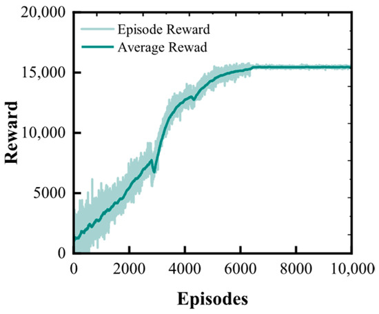
Figure 9.
Height–thrust vector collaborative optimization training convergence curve.
4.3.2. Drone Parameter Analysis Under Hybrid Aerodynamic–Thrust Vector Control
The aerodynamic force/thrust vector collaborative optimization scheme based on the improved DDPG algorithm breaks through the limitations of traditional single-parameter optimization, achieving synchronized dynamic optimization of flight height and thrust vector angles. As shown in Figure 10, the collaborative optimization strategy demonstrates control characteristics significantly different from the aforementioned schemes: the collaborative optimization scheme adopts a continuous climbing trajectory from 23 km to 26.5 km, achieving a height variation range of approximately 3.5 km compared to the fixed height strategy of previous schemes. This dynamic climbing strategy fully exploits the atmospheric environment differences at various heights, utilizing the relatively high-density atmosphere at lower heights for better aerodynamic efficiency in the early flight phase, then gradually climbing to higher heights to reduce drag effects. The thrust vector angle exhibits distinct segmented characteristics, maintaining a relatively stable angle of approximately 25° during the 0–1200 s cruise phase, then rapidly adjusting to 20° after 1200 s. This segmented angle strategy forms a synergistic effect with the height climbing trajectory, employing the most suitable thrust vector configuration for different flight phases. The continuous height climbing and segmented thrust vector angle adjustment form a complex collaborative optimization pattern. The DDPG algorithm can simultaneously optimize height change rate and thrust vector angle according to real-time flight states, achieving optimal matching of the two key control parameters, which represents a technical breakthrough that cannot be achieved by the aforementioned single-parameter optimization schemes. Under the time-varying thrust vector control strategy, the range is further improved by 45.36 km.
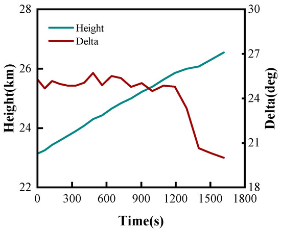
Figure 10.
Results of collaborative optimization control strategy.
As shown in Figure 11a,b, the equivalence ratio comparison and specific impulse comparison results demonstrate that collaborative optimization control maintains more stable equivalence ratios, and collaborative optimization control performs similarly to time-varying control in combustion efficiency. Figure 11c shows that the mass flow rate comparison indicates the fuel consumption rates of collaborative optimization control and time-varying thrust vector control are almost identical, with the two curves virtually overlapping. This indicates that the performance improvement of collaborative optimization primarily stems from aerodynamic characteristic improvements rather than changes in propulsion system efficiency and fuel economy, validating the core role of height–thrust vector collaborative adjustment in aerodynamic optimization.
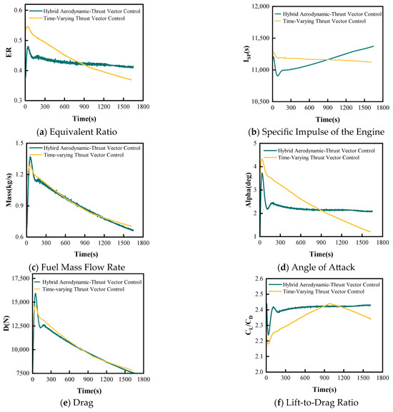
Figure 11.
Comparison of drone parameters between hybrid aerodynamic–thrust vector control and time-varying thrust vector control.
Figure 11d shows that the angle of attack comparison demonstrates that collaborative optimization control achieves significant improvement in attitude control stability. The angle of attack of the collaborative optimization scheme rapidly adjusts to approximately 2° in the early flight phase and remains relatively stable, compared to the significant variation from 4.5° to 1.5° in time-varying thrust vector control, resulting in much smoother angle of attack control. This stable low-angle of attack control benefits from the collaborative adjustment of height climbing and thrust vector, which regulates the atmospheric environment through height changes, reducing the need for large angle of attack adjustments and thus achieving superior aerodynamic drag characteristics. Figure 11e shows that the drag comparison indicates the drag characteristics of collaborative optimization control and time-varying control are essentially similar, both achieving good drag control effects. This result demonstrates that the main advantage of collaborative optimization is not reflected in further reduction of absolute drag values.
As a comprehensive indicator of aerodynamic performance, the lift-to-drag ratio shows that collaborative optimization control exhibits further improvement compared to time-varying control. As shown in Figure 11f, collaborative optimization maintains a more stable high lift-to-drag ratio level throughout the entire flight process, which is attributed to the precise matching of height climbing trajectory and thrust vector angles, enabling maintenance of near-optimal aerodynamic configurations across different flight phases.
4.4. Robustness Analysis Under Uncertainty of Aerodynamic Coefficients
To verify the applicability of the proposed continuous linear parameterization strategy and the ResNet-DDPG framework to different hypersonic drone configurations, and to further mitigate possible discrepancies arising from neglected real gas hypersonic effects, we deliberately introduce systematic perturbations to the lift and drag coefficients in the robustness tests. This section analyzes the robustness and generalization ability of the algorithm through aerodynamic coefficient perturbation experiments. This bias-perturbation analysis demonstrates that the proposed ResNet-DDPG framework maintains performance even when aerodynamic coefficients deviate from the baseline database. These two parameters directly determine the aerodynamic characteristics and flight performance of the hypersonic drones. In practical engineering applications, different drones have varying aerodynamic characteristics. Therefore, it is necessary to verify the performance stability of the algorithm under changes in aerodynamic parameters.
The size of the lift coefficient and drag coefficient of the aircraft is adjusted to explore their impact on the performance of range optimization. The ratios of the adjusted sizes to the original sizes are, respectively, denoted as XD and XL. Within the range of (0.8, 1.2), the impact of different combinations of aerodynamic coefficients on the improvement of range is examined, and orthogonal experimental methods are employed for systematic analysis. The experimental settings include five representative combinations of aerodynamic coefficients, covering the typical range of parameter variations. Table 2 shows the improvement of the range under different combinations of aerodynamic coefficients:

Table 2.
The improvement of range under different combinations of aerodynamic coefficients.
The experimental results demonstrate that the algorithm successfully converged under all tested operating conditions, thereby proving its robust adaptability. The range improvement varied from 113.58 to 355.61 km, with even the most unfavorable aerodynamic conditions yielding an increase of over 100 km. Operating Conditions 2 and 5 both achieved significant range improvements close to 300 km, while Operating Conditions 3 and 4, though relatively less effective, still maintained a basic level of optimization.
These findings indicate that the proposed continuous linear parameterization strategy and the ResNet-DDPG framework exhibit excellent robustness against variations in aerodynamic parameters. This robustness lays a solid technical foundation for the algorithm’s application and promotion across different drone configurations. The algorithm’s ability to maintain stable optimization performance in the face of ±20% aerodynamic parameter perturbations highlights its strong engineering applicability.
4.5. Computational Efficiency Analysis
This section provides a comparative analysis of the computational efficiency of three control strategies to guide engineering applications. All experiments were conducted on identical hardware platforms (Intel i7-13700 + RTX 3060 12G).
Network Architecture and Parameter Scale:
The ResNet-DDPG algorithm employs a deep residual network architecture. The residual Actor network features a 7-layer structure (4 → 512 → 384 → 256 → 192 → 128 → 64 → 21/42) with residual connections between the 3rd and 5th layers, totaling approximately 450,000 parameters. The residual Critic network adopts a 9-layer structure comprising a state encoding pathway (4 → 384 → 256 → 192), an action encoding pathway, and a fusion pathway, with a total of approximately 600,000 parameters. In contrast, conventional DDPG networks with shallow architectures (typically 2–3 layers) contain only around 100,000 parameters.
Training Complexity Comparison:
The PSO algorithm optimizes 2 fixed parameters using 30 particles with convergence achieved in approximately 25 iterations, requiring 4 h of training time. ResNet-DDPG (21-dimensional) requires training over approximately 2500 episodes, with each episode containing 1800 time steps of forward propagation and experience replay updates, resulting in 12 h of training time. ResNet-DDPG (42-dimensional), due to the doubled action space dimensionality, faces significantly increased convergence difficulty, requiring approximately 7000 episodes with a training time of 40 h.
Performance-Efficiency Trade-off:
The training time ratio is PSO:ResNet-DDPG(21-dim):ResNet-DDPG(42-dim) = 1:3:10, while achieving substantial improvements in range performance. Considering the “offline training, online deployment” characteristics of UAV applications, the residual network inference time is only on the order of milliseconds, satisfying real-time control requirements.
5. Conclusions
This paper addresses the cruise range maximization problem for hypersonic drones by proposing an aerodynamic force/thrust vector combined trajectory optimization method. Through constructing three progressively complex control schemes, the study systematically explores the impact mechanisms of different aerodynamic force and thrust vector combination modes on range performance.
The research first establishes a fixed thrust vector control scheme based on the PSO algorithm, obtaining an optimal flight height of 24.7 km and a fixed thrust vector deflection angle through offline optimization. Compared to pure aerodynamic control at planned deployment height, this scheme achieves approximately 95.04 km range improvement, validating the fundamental advantages of thrust vector technology. Performance improvement mechanism analysis demonstrates that fixed thrust vector control achieves performance enhancement through dual optimization of aerodynamic characteristics and fuel consumption, significantly improving lift-to-drag ratio characteristics, reducing drag levels, and enhancing combustion efficiency.
Building upon fixed control, the research further proposes a time-varying thrust vector control scheme based on the DDPG algorithm integrated with deep residual networks. This scheme innovatively employs a continuous linear parameterization strategy, using only 21 parameters (20 variation rates plus 1 initial value) to achieve continuous thrust vector control throughout the entire flight process. Compared to traditional segmented control methods, this strategy effectively reduces parameter dimensionality and addresses the problems of sparse rewards and training difficulties in reinforcement learning. Time-varying control achieves an additional 5.7 km range improvement over fixed control through a staged thrust vector angle optimization strategy, increasing the peak lift-to-drag ratio from 2.4 to 2.45. The key technical insight is that dynamic adjustment of the thrust vector vertical component provides variable lift assistance to the drone, which is the fundamental reason for lift-to-drag ratio improvement rather than propulsion system performance enhancement itself.
The highest level of the research is the collaborative optimization control scheme based on an improved DDPG algorithm, achieving dual-dimensional collaborative adjustment of thrust vector and flight height. This scheme combines a dynamic height climbing strategy (23 km → 26.5 km) with precise thrust vector matching, making angle of attack control smoother, further improving the lift-to-drag ratio to 2.5, with total range improvement of approximately 146.14 km. The core advantage of collaborative optimization lies in height changes directly affecting atmospheric density and aerodynamic characteristics, while thrust vector angles determine thrust allocation between lift and propulsion directions. The collaborative adjustment of both enables local optimization in different regions of the flight envelope, thereby achieving significant global performance improvement.
Performance comparison of the three control schemes validates the applicability of traditional optimization algorithms to deep reinforcement learning algorithms in complex trajectory optimization problems. PSO algorithm demonstrates good convergence and stability in fixed parameter optimization, while DDPG algorithm exhibits powerful adaptive optimization capability in multi-dimensional continuous control spaces, particularly showing significant advantages in handling complex constraint conditions and multi-objective optimization problems.
From an engineering practicality perspective, fixed thrust vector control features simple control, high reliability, and easy engineering implementation, making it suitable for application scenarios with relatively lower performance requirements but higher system stability demands. Time-varying thrust vector control achieves a good balance between performance and complexity, obtaining significant performance improvements through relatively simple parameterization strategies, and has promising engineering application prospects. Collaborative optimization control represents the cutting-edge direction of technological development. Although it has higher system complexity, it possesses important application value in special missions with stringent requirements for ultimate performance.
Author Contributions
Conceptualization, Z.Z. and Y.Z.; methodology, Z.Z.; software, Z.Z.; validation, Z.Z., Y.Z., L.Y., W.J., and J.W.; formal analysis, Z.Z.; investigation, Z.Z.; resources, Y.Z.; data curation, Z.Z.; writing—original draft preparation, Z.Z.; writing—review and editing, Y.Z. and L.Y.; visualization, Z.Z.; supervision, Y.Z. and L.Y.; project administration, Y.Z.; funding acquisition, Y.Z. All authors have read and agreed to the published version of the manuscript.
Funding
This research was partly funded by the National Natural Science Foundation of China (NSFC) under Grant No. 12302382.
Data Availability Statement
The datasets collected and generated in this study are available upon request to the corresponding author.
Conflicts of Interest
The authors declare no conflicts of interest.
References
- Ding, Y.; Yue, X.; Chen, G.; Si, J. Review of Control and Guidance Technology on Hypersonic Vehicle. Chin. J. Aeronaut. 2022, 35, 1–18. [Google Scholar] [CrossRef]
- Zhao, Z.; Huang, W.; Yan, L.; Yang, Y. An Overview of Research on Wide-Speed Range Waverider Configuration. Prog. Aerosp. Sci. 2020, 113, 100606. [Google Scholar] [CrossRef]
- German, B.; Patterson, M.; Pate, D.; Takahashi, T. Reachability of Optimal Cruise Conditions. In Proceedings of the 50th AIAA Aerospace Sciences Meeting Including the New Horizons Forum and Aerospace Exposition, Nashville, TN, USA, 9–12 January 2012; American Institute of Aeronautics and Astronautics: Reston, VA, USA, 2012. [Google Scholar] [CrossRef]
- Zhou, H.C. Design of Hypersonic Vehicle Time-Delay Compensation Controller Based on Dynamic Surface Control. Int. J. Veh. Struct. Syst. (IJVSS) 2023, 15, 258–261. [Google Scholar] [CrossRef]
- Tarpley, C.; Lewis, M.J. Stability Derivatives for a Hypersonic Caret-Wing Waverider. J. Aircr. 1995, 32, 795–803. [Google Scholar] [CrossRef]
- Chuang, C.-H.; Morimoto, H. Sub-Optimal and Optimal Periodic Solutions for Hypersonic Transport. In Proceedings of the 1995 American Control Conference—ACC’95, Seattle, WA, USA, 21–23 June 1995; Volume 2, pp. 1186–1190. [Google Scholar] [CrossRef]
- French, M. Adaptive Control and Robustness in the Gap Metric. IEEE Trans. Autom. Control 2008, 53, 461–478. [Google Scholar] [CrossRef]
- Hambidge, C.; Ivison, W.; Steuer, D.; Neely, A.; McGilvray, M. Investigation of Fluidic Thrust Vectoring for Scramjets. Exp. Fluids 2023, 64, 75. [Google Scholar] [CrossRef]
- Xu, J.; Gu, R.; Huang, S. Exploring the Impact of Vector Thrust on Aircraft Maneuverability Utilizing Bypass Dual Throat Nozzle Technology. Aerosp. Sci. Technol. 2025, 156, 109765. [Google Scholar] [CrossRef]
- Sahbon, N.; Jacewicz, M.; Lichota, P.; Strzelecka, K. Path-Following Control for Thrust-Vectored Hypersonic Aircraft. Energies 2023, 16, 2501. [Google Scholar] [CrossRef]
- Venkateswara Rao, D.M.K.K.; Go, T.H. Perching Trajectory Optimization Using Aerodynamic and Thrust Vectoring. Aerosp. Sci. Technol. 2013, 31, 1–9. [Google Scholar] [CrossRef]
- Werner, L.; Strohmeier, M.; Rothe, J.; Montenegro, S. Thrust Vector Observation for Force Feedback-Controlled UAVs. Drones 2022, 6, 49. [Google Scholar] [CrossRef]
- Martinez, R.R.; Paul, H.; Shimonomura, K. Aerial Torsional Work Utilizing a Multirotor UAV with Add-on Thrust Vectoring Device. Drones 2023, 7, 551. [Google Scholar] [CrossRef]
- Ding, H.; Xu, B.; Yang, W.; Zhou, Y.; Wu, X. A Robust Control Method for the Trajectory Tracking of Hypersonic Unmanned Flight Vehicles Based on Model Predictive Control. Drones 2025, 9, 223. [Google Scholar] [CrossRef]
- Liu, F.; Lu, L.; Zhang, Z.; Xie, Y.; Chen, J. Intelligent Trajectory Prediction Algorithm for Hypersonic Vehicle Based on Sparse Associative Structure Model. Drones 2024, 8, 505. [Google Scholar] [CrossRef]
- Mahmood, A.; Rehman, F.; Bhatti, A.I. Trajectory optimization of a subsonic unpowered gliding vehicle using control vector parameterization. Drones 2022, 6, 360. [Google Scholar] [CrossRef]
- Srivastava, K.; Pandey, P.C.; Sharma, J.K. An approach for route optimization in applications of precision agriculture using UAVs. Drones 2020, 4, 58. [Google Scholar] [CrossRef]
- Yang, Y.; Xiong, X.; Yan, Y. UAV Formation Trajectory Planning Algorithms: A Review. Drones 2023, 7, 62. [Google Scholar] [CrossRef]
- Wu, Q.; Su, Y.; Tan, W.; Zhan, R.; Liu, J.; Jiang, L. UAV Path Planning Trends from 2000 to 2024: A Bibliometric Analysis and Visualization. Drones 2025, 9, 128. [Google Scholar] [CrossRef]
- Gugan, G.; Haque, A. Path Planning for Autonomous Drones: Challenges and Future Directions. Drones 2023, 7, 169. [Google Scholar] [CrossRef]
- Gelli, M.; Bigazzi, L.; Boni, E.; Basso, M. Suboptimal Trajectory Planning Technique in Real UAV Scenarios with Partial Knowledge of the Environment. Drones 2024, 8, 211. [Google Scholar] [CrossRef]
- Rodriguez, A.A.; Shekaramiz, A.A.; Masoum, M.A.S. Computer Vision-Based Path Planning with Indoor Low-Cost Autonomous Drones: An Educational Surrogate Project for Autonomous Wind Farm Navigation. Drones 2024, 8, 154. [Google Scholar] [CrossRef]
- Wang, C.; Cao, R.; Wang, R. Learning Discriminative Topological Structure Information Representation for 2D Shape and Social Network Classification via Persistent Homology. Knowl.-Based Syst. 2025, 311, 113125. [Google Scholar] [CrossRef]
- Wang, C.; Gao, X.; Wu, M.; Lam, S.-K.; He, S.; Tiwari, P. Looking Clearer with Text: A Hierarchical Context Blending Network for Occluded Person Re-Identification. IEEE Trans. Inf. Forensics Secur. 2025, 20, 4296–4307. [Google Scholar] [CrossRef]
- Liu, X.; Zhong, W.; Wang, X.; Duan, H.; Fan, Z.; Jin, H.; Huang, Y.; Lin, Z. Deep Reinforcement Learning-Based 3D Trajectory Planning for Cellular Connected UAV. Drones 2024, 8, 199. [Google Scholar] [CrossRef]
- Yang, T.; Yang, F.; Li, D. A New Autonomous Method of Drone Path Planning Based on Multiple Strategies for Avoiding Obstacles with High Speed and High Density. Drones 2024, 8, 205. [Google Scholar] [CrossRef]
- Sheng, Y.; Liu, H.; Li, J.; Han, Q. UAV Autonomous Navigation Based on Deep Reinforcement Learning in Highly Dynamic and High-Density Environments. Drones 2024, 8, 516. [Google Scholar] [CrossRef]
- Wang, J.; Yu, Z.; Zhou, D.; Shi, J.; Deng, R. Vision-Based Deep Reinforcement Learning of Unmanned Aerial Vehicle (UAV) Autonomous Navigation Using Privileged Information. Drones 2024, 8, 782. [Google Scholar] [CrossRef]
- Fang, Z.; Savkin, A.V. Strategies for Optimized UAV Surveillance in Various Tasks and Scenarios: A Review. Drones 2024, 8, 193. [Google Scholar] [CrossRef]
- Azar, A.T.; Koubaa, A.; Mohamed, N.A.; Ibrahim, H.A.; Ibrahim, Z.F.; Kazim, M.; Ammar, A.; Benjdira, B.; Khamis, A.M.; Hameed, I.A.; et al. Drone deep reinforcement learning: A review. Electronics 2021, 10, 999. [Google Scholar] [CrossRef]
- Zhou, Y.; Xia, Z.; Ding, F.; Huang, W. Upgraded Design Methodology for Airframe/Engine Integrated Full-Waverider Vehicle Considering Thrust Chamber Design. Acta Astronaut. 2023, 211, 1–14. [Google Scholar] [CrossRef]
- Gu, R.; Xu, J.; Guo, S. Experimental and Numerical Investigations of a Bypass Dual Throat Nozzle. J. Eng. Gas Turbines Power 2014, 136, 084501. [Google Scholar] [CrossRef]
- Gu, R.; Xu, J. Dynamic Experimental Investigations of a Bypass Dual Throat Nozzle. J. Eng. Gas Turbines Power 2015, 137, 084501. [Google Scholar] [CrossRef]
- Gao, H.; Chen, Z.; Sun, M.; Wang, Z.; Chen, Z. General Periodic Cruise Guidance Optimization for Hypersonic Vehicles. Appl. Sci. 2020, 10, 2898. [Google Scholar] [CrossRef]
Disclaimer/Publisher’s Note: The statements, opinions and data contained in all publications are solely those of the individual author(s) and contributor(s) and not of MDPI and/or the editor(s). MDPI and/or the editor(s) disclaim responsibility for any injury to people or property resulting from any ideas, methods, instructions or products referred to in the content. |
© 2025 by the authors. Licensee MDPI, Basel, Switzerland. This article is an open access article distributed under the terms and conditions of the Creative Commons Attribution (CC BY) license (https://creativecommons.org/licenses/by/4.0/).