Article

Motion Control of Gallium-Based Liquid Metal Droplets in Abrasive Suspensions Within a Flow Channel

College of Mechanical and Electrical Engineering, Soochow University, Suzhou 215021, China
*
Author to whom correspondence should be addressed.
Actuators 2025, 14(9), 456; https://doi.org/10.3390/act14090456
Submission received: 5 August 2025 / Revised: 13 September 2025 / Accepted: 15 September 2025 / Published: 18 September 2025
(This article belongs to the Section Control Systems)

Abstract

Gallium-based room-temperature liquid metal is a promising multifunctional material for microfluidics and precision machining due to its high mobility and deformability. However, precise motion control of gallium-based liquid metal droplets, especially in abrasive particle-laden fluids, remains challenging. This study presents a hybrid control framework for regulating droplet motion in a one-dimensional PMMA channel filled with NaOH-based SiC abrasive suspensions. A dynamic model incorporating particle size and concentration effects on the damping coefficient was established. The system combines a setpoint controller, high-resolution voltage source, and vision feedback to guide droplets to target positions with high accuracy. Experimental validation and MATLAB simulations confirm that the proposed dynamic damping control strategy ensures stable, rapid, and precise positioning of droplets, minimizing motion fluctuations. This approach offers new insights into the manipulation of gallium-based liquid metal droplets for targeted material removal in micro-manufacturing, with potential applications in microelectronics and high-precision surface finishing.

1. Introduction

Gallium-based liquid-metal (LM) alloys [1] such as eutectic gallium indium (EGaIn, mp 15.5   ° C ) and gallium indium tin (Galinstan, m.pt. 15.5   ° C ) have been attracting more attention from researchers in recent years. The unique physical/chemical properties of LM, such as high thermal/electrical conductivity( 3.4 × 10 6   S m 1 ), extreme flexibility, a large surface tension ( > 400   m N   m 1 ), an extremely low vapor pressure (<10−6 Pa at 500 °C), and relatively low toxicity compared to mercury [2] and their ability to form a thin oxide shell when exposed to oxygen [3] has many applications. These exceptional characteristics make room-temperature liquid metals promising for a wide range of applications, such as soft and stretchable electronic components [4,5,6,7], devices [8,9,10], small-scale vehicles and robots [11,12], soft sensors [13,14], tunable antennas and apertures [15,16], as well as fluidic optical components and displays [17,18]. Furthermore, liquid metals hold significant potential for the development of soft robots [19], a long-standing ambition in engineering. Despite these advances, precise control of the surface tension of liquid metals, a critical factor for achieving desired motion and deformation, remains a key challenge. Addressing this issue is essential for unlocking the full potential of these materials in next-generation applications.
In the application environment of liquid metal droplets, NaOH solution is commonly employed as the electrolyte, not only to facilitate the dissolution of the native oxide layer on the liquid metal surface but also to promote the formation of a stable electrical double layer, thereby enabling electrocapillary actuation and maintaining surface activity during operation [20]. When abrasive particles, such as silicon carbide, are introduced into the NaOH solution at varying particle sizes and concentrations, the rheological properties of the solution undergo significant changes, resulting in the formation of a distinct “rheological fluid.” The presence of these abrasive particles alters the viscosity and flow characteristics of the solution, which, under the influence of an applied electric field, can affect the motion of the liquid metal. Specifically, the particle size and concentration may directly influence factors such as the viscosity, surface tension, and shear resistance of the solution.
Despite the vast potential of liquid metal droplets in various applications, precise control of their motion in abrasive particle-laden fluids presents significant challenges. The random distribution of abrasive particles within the fluid introduces additional resistance to the motion of liquid metal droplets, thereby influencing their trajectory and velocity [21]. Particularly under the influence of an electric field, the interaction mechanisms between the liquid metal and the abrasive particles become more complex. Effectively controlling the motion and velocity of liquid metal droplets through the electric field, therefore, remains a critical issue that must be addressed. Consequently, the development of new control strategies and mathematical models to tackle the challenges of liquid metal motion control in abrasive particle-laden fluids is of paramount importance.
Various methods have been developed to manipulate liquid metal droplets, which can be broadly categorized into several approaches: electrical fields [22,23], magnetic fields [24,25], electrochemical reactions [26,27], photochemical processes [28], and ionic imbalance [29]. Among these, the application of an external electric field in an ionic NaOH solution to actively control the surface tension of liquid metal droplets is the most widely employed, due to its practicality and ease of implementation. According to Lippmann’s equation, the external electric field can disrupt the charge distribution within the electrical double layer (EDL) at the liquid metal- NaOH solution interface, thereby generating a surface tension gradient along the liquid metal droplet’s surface. This gradient induces motion and deformation of the droplet [30].
Numerous studies have explored the use of electric fields to drive the movement of liquid metal droplets. For instance, a direct current (DC) electric field has been applied to drive a mercury slug within a microfluidic channel, with the average speed of the mercury theoretically estimated [31]. Similarly, gallium-based liquid metal droplets have been shown to exhibit linear and reciprocating motion under DC and alternating current (AC) electric fields, respectively, as reported in [23,30,32]. More recently, a low-power, high-efficiency micropump was developed by applying an AC electric field with a DC offset to a Galinstan (68.5 wt% gallium, 21.5   w t % indium, and 10   w t %   t i n ) droplet confined within a cylindrical chamber embedded in fluidic chips [33]. As shown in the work by Xie et al. [34], liquid metal droplet motion control is critical in a variety of applications such as soft robotics and microfluidics. Despite these advancements, precise control of liquid metal droplet motion remains a significant challenge, with many aspects still to be fully understood. However, existing research has predominantly focused on the motion control of liquid metals in homogeneous fluids, such as pure NaOH solutions, with relatively little attention given to the motion characteristics of liquid metals in abrasive particle-laden fluids.
In abrasive particle-laden fluids, the presence of solid particles markedly alters the rheological properties of the medium—including viscosity, density, and surface tension—which in turn significantly affects the dynamics of liquid metal droplets subjected to external electric fields [35]. Despite this, the specific roles of particle size and concentration in modulating these effects remain insufficiently explored in the literature. Addressing this knowledge gap, the present study systematically investigates the motion behavior of liquid metal droplets in NaOH-based abrasive suspensions with varied SiC particle sizes and concentrations under applied electric fields. By quantitatively analyzing how these particle characteristics influence the viscosity of the mixed solution and the damping term in the liquid metal dynamic equation, we establish a comprehensive control strategy for achieving precise manipulation of liquid metal droplets in complex fluid environments. The findings offer new theoretical and practical insights for optimizing liquid metal motion and surface processing in multiphase microfluidic systems.
To achieve the aforementioned objectives, we have established an advanced experimental platform, which integrates a programmable power supply, an industrial camera imaging system, and a comprehensive data acquisition and feedback control unit. Initially, a dynamic model was constructed to elucidate the motion behavior of liquid metal droplets subjected to an external electric field, with particular emphasis on the roles of surface tension-driven forces, viscous resistance, and channel wall friction. Building upon this model, we designed a setpoint controller that leverages real-time visual feedback to compute the optimal voltage input, thereby enabling precise manipulation of droplet motion via PID control.
The validity and robustness of the proposed control methodology were systematically demonstrated through experiments conducted in PMMA-based microfluidic channels. Overall, this hybrid control framework is expected to enable highly accurate regulation of liquid metal droplet dynamics, while also offering new perspectives for the application of liquid metals in complex fluidic environments. Furthermore, our results highlight the significant potential of this approach for high-precision material removal, providing valuable insights for advanced micro-manufacturing processes where stringent surface quality control is required.

2. Materials and Methods

2.1. Experimental Setup and Materials

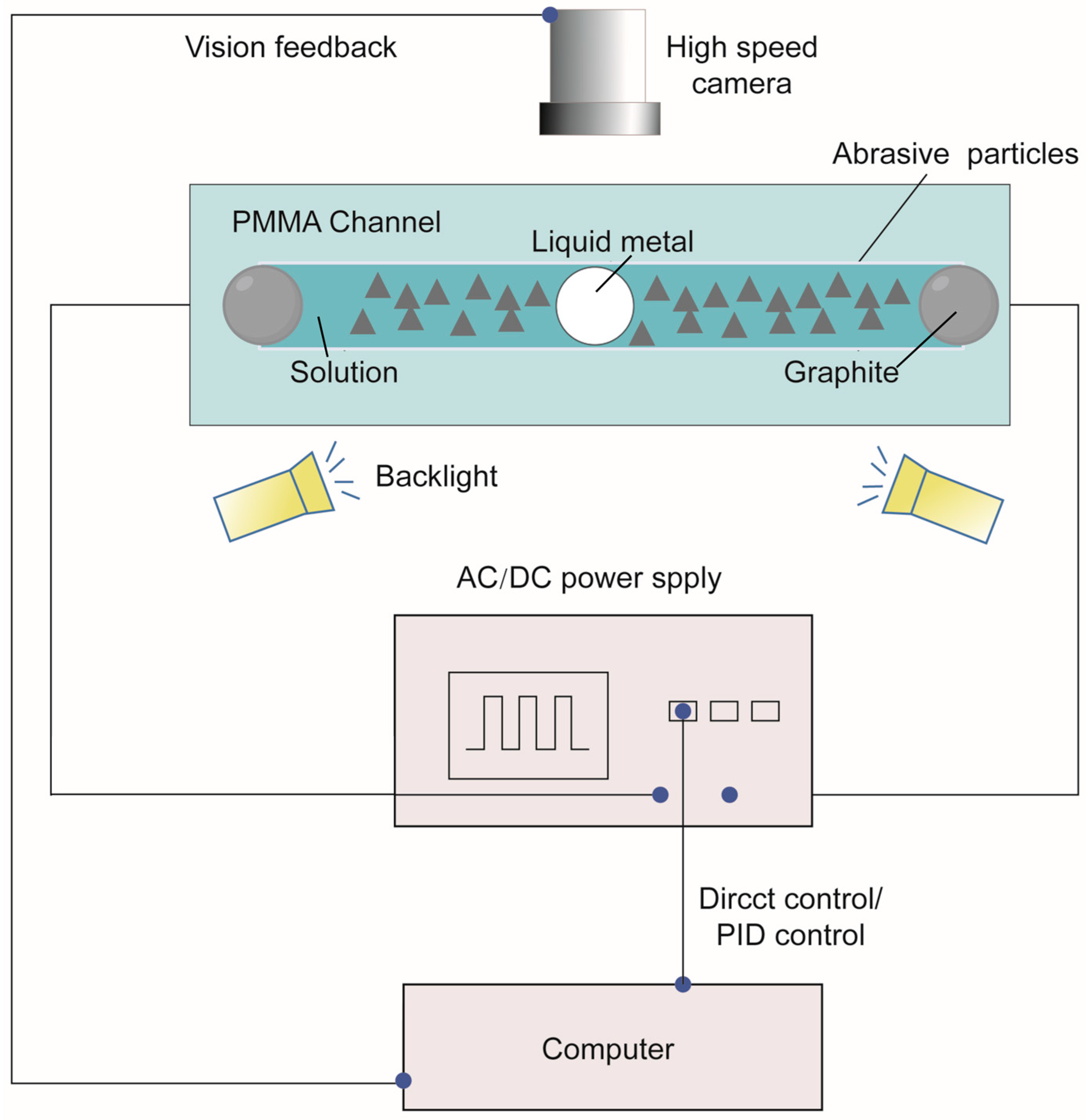
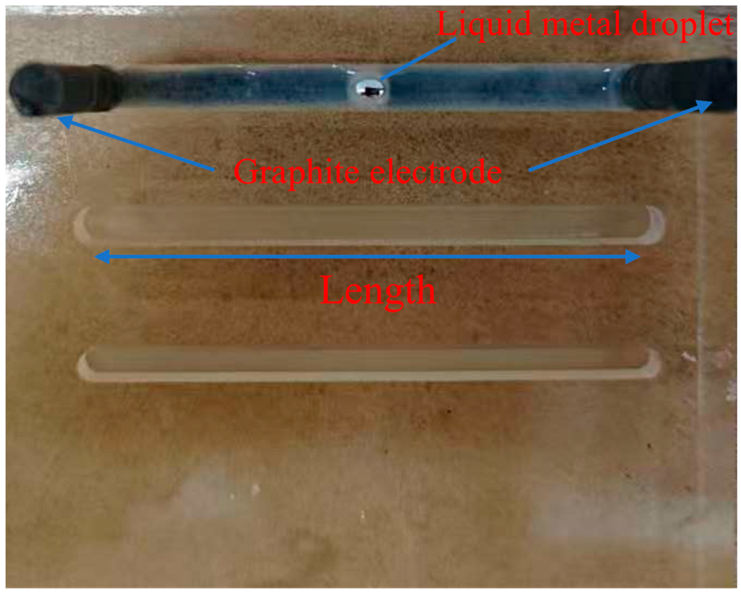
In the experiment, as illustrated in Figure 1, EGaln ( 75   w t % gallium, 25   w t % indium) was employed as the droplet material. The droplets were dispensed into open-top PMMA channels with widths of 3 , 4 , 5 , 6 , and 7 mm and a fixed length of 80 mm. Using a syringe, EGaln droplets with radii ranging from 0.15 cm to 0.35 cm were generated and introduced into the channels. A series of abrasive suspensions with varying particle sizes ( 100   μ m to 500   μ m ) and volume concentrations ( 2 % to 10 % ) were prepared. To ensure uniform dispersion of SiC particles in the NaOH solution, a magnetic stirrer was used. All abrasive particles were classified using standard sieves: 170 mesh (90–106 μ m ), 120 mesh (125–150 μ m ), 80 mesh (180–212 μ m ), 60 mesh (250–270 μm), and 50 mesh (270–300 μ m ). Both the NaOH solution and silicon carbide (SiC) were supplied by Dongguan Zhongwei Abrasive Technology Co., Ltd., Dongguan, China. The viscosity of each suspension was measured using a viscometer under different SiC particle size and concentration conditions to evaluate their effects on the solution’s viscosity. The input voltage was applied via a programmable AC/DC power supply (ITECH IT7221, ITECH Electronic Co., Shenzhen, China). Additionally, an MV-CU060-10GC camera (Hikvision, Hangzhou, China) was employed to record the experiments and acquire real-time position data of the liquid metal, which was transmitted to the controller to enable real-time tracking of droplet position, velocity, and acceleration. The precise control framework for liquid metal droplet dynamics is schematically presented in Figure 2. The actual experimental channel are shown in Figure 3.

2.2. Experimental Procedure and Closed-Loop Control

The acquired position data was transmitted to a MATLAB-based controller for closed-loop feedback regulation. In particular, MATLAB was utilized to integrate and coordinate the experimental system, making extensive use of the Image Acquisition Toolbox, Image Processing Toolbox, and Instrument Control Toolbox for real-time image acquisition, object recognition, system control, and data recording. The overall hybrid control framework, enabling precise manipulation of liquid metal droplet dynamics under varying abrasive conditions, is schematically illustrated in Figure 2.
The electrolyte was a 0.5   m o l / L N a O H alkaline solution that filled all channels. The electrode was graphite electrode whose size is ϕ 10 × 20   m m . We obtained the accurate displacement measurement of the liquid metal droplet every 0.1 s from the video using MATLAB R2022a (MathWorks, Natick, MA, USA) software. Next, based on the displacement data, we calculated the velocity and acceleration of liquid metal droplet using matlab software. From the definition in (A18), we obtain that K 2 , 0 = 0.045   m P a · s and K 3 = 0.0001 . All open-top PMMA channel samples used in the experiment had a rectangular cross-section with a width and depth of 5 mm, and lengths of 40, 50, 60, 70, or 80 mm. The height of the solution must enable the solution to cover the liquid metal droplet [34].
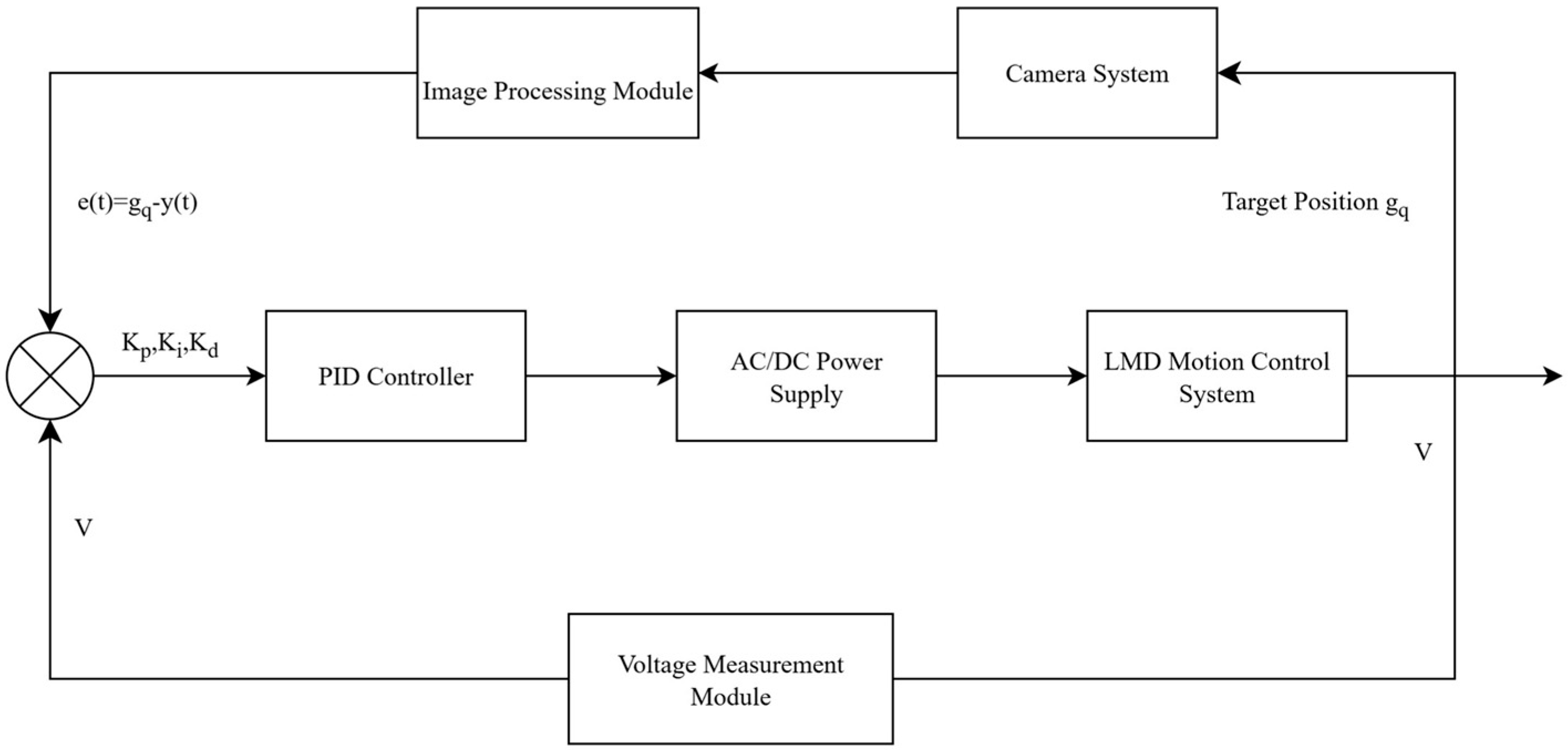
The liquid metal droplet is highly sensitive to circuit voltage due to its extremely high surface tension, with even a small voltage fluctuation in the circuit sufficient to induce a displacement in the static liquid metal droplet. Although the voltage output module of the AC/DC power supply (ITECH IT7221, ITECH Electronic Co., Shenzhen, China) has a precision exceeding 0.1 V, it does not provide adequate voltage accuracy. Therefore, we propose a voltage output strategy that enables high-resolution voltage output to the circuit, as shown in Figure 4. The AC/DC power supply’s voltage output module has an accuracy of 0.1 V, used for providing output voltages to the two electrodes. Additionally, the voltage measurement module of the AC/DC power supply (ITECH IT7221, ITECH Electronic Co., Shenzhen, China) has a measurement accuracy of 0.1 V and is employed to measure the input voltage to the control circuit, feeding back any deviations to the PID controller, formulated as follows:
u ( k ) = K p e ( k ) + K i i = 0 k   e ( i ) d t + K d e ( k ) e ( k 1 ) d t
where e ( k ) represents the error at the k -th step, i = 0 k   e ( i ) d t is the cumulative integral error, and e ( k ) e ( k 1 ) d t denotes the differential error. u ( k ) represents the output voltage error. The control gains are k i = 0.1 , k d = 1 , and k p = 6 .
Thanks to the above strategy, the enhanced power supply ensures that the voltage output accuracy meets the control requirements, with a response time of less than 300 ms. These parameters generally require iterative tuning during the experimental process, based on factors such as droplet mass, channel resistance, response speed requirements, and the intensity of external disturbances.
As illustrated in Figure 4, in the proposed control system, position feedback plays a critical role in achieving precise motion control of the droplet. The position feedback is obtained through real-time image processing, where the droplet’s centroid is extracted from the captured images. This feedback signal is subsequently used to compute the position error, which is defined as the difference between the target position ( g q ) and the actual position of the droplet. The position error, denoted as e ( t ) = g q y ( t ) , serves as the primary input to the PID controller, enabling continuous adjustment of the control signal.
The closed-loop system continuously compares the desired position with the actual position, thus allowing the PID controller to dynamically adjust the voltage output. This voltage, in turn, influences the droplet’s movement, ensuring it follows the target trajectory with minimal deviation. The real-time feedback mechanism effectively mitigates steady-state errors and improves the overall system stability, ensuring the droplet reaches the target position with high precision.
By incorporating position feedback into the control loop, the system compensates for any disturbances or inaccuracies in the motion, making it adaptive to changes in the environment or system parameters. This feedback-driven approach is crucial for maintaining high-accuracy control in systems where precise positioning is essential. The detailed theoretical analysis of the liquid metal droplet dynamics modeling and controller design is provided in Appendix A.
To evaluate the proposed strategy, simulations are conducted under three key scenarios: varying target positions, droplet sizes, and damping coefficients modulated by particle size and concentration.
The experimental design encompassed three scenarios: (1) varying the target positions (20–40 mm) to evaluate the system’s positional accuracy at different distances; (2) altering the droplet radii to assess the robustness of the control system under different droplet properties; and (3) adjusting the particle size and concentration of the abrasive fluid to test the system’s adaptability to environmental changes. Each experimental configuration was repeated more than 50 times to ensure statistical reliability and minimize random errors. The processed experimental data were compared with simulation results to analyze trends in position, velocity, and acceleration.

3. Results and Discussion

The motion control of liquid metal droplets in abrasive suspensions is a complex task influenced by factors such as viscous resistance, friction, and external driving forces. This study proposes a closed-loop control strategy based on a PID controller, which dynamically adjusts the applied voltage in response to real-time feedback of the droplet’s position and velocity. By employing this approach, the droplet achieves rapid response and high-precision localization, even under varying environmental conditions. The theoretical foundation of the control system is validated through Lyapunov stability analysis, ensuring robust convergence and stability.
To evaluate the proposed strategy, simulations are conducted under three key scenarios: varying target positions, droplet sizes, and damping coefficients modulated by particle size and concentration. These simulations demonstrate the adaptability and effectiveness of the control system in achieving precise motion control. The findings not only provide theoretical insights into the dynamics of liquid metal droplets but also offer practical guidance for their integration into advanced microfluidic devices and flexible electronics, addressing critical challenges in precision engineering.

3.1. Motion Response of Liquid Metal Droplets at Different Target Positions

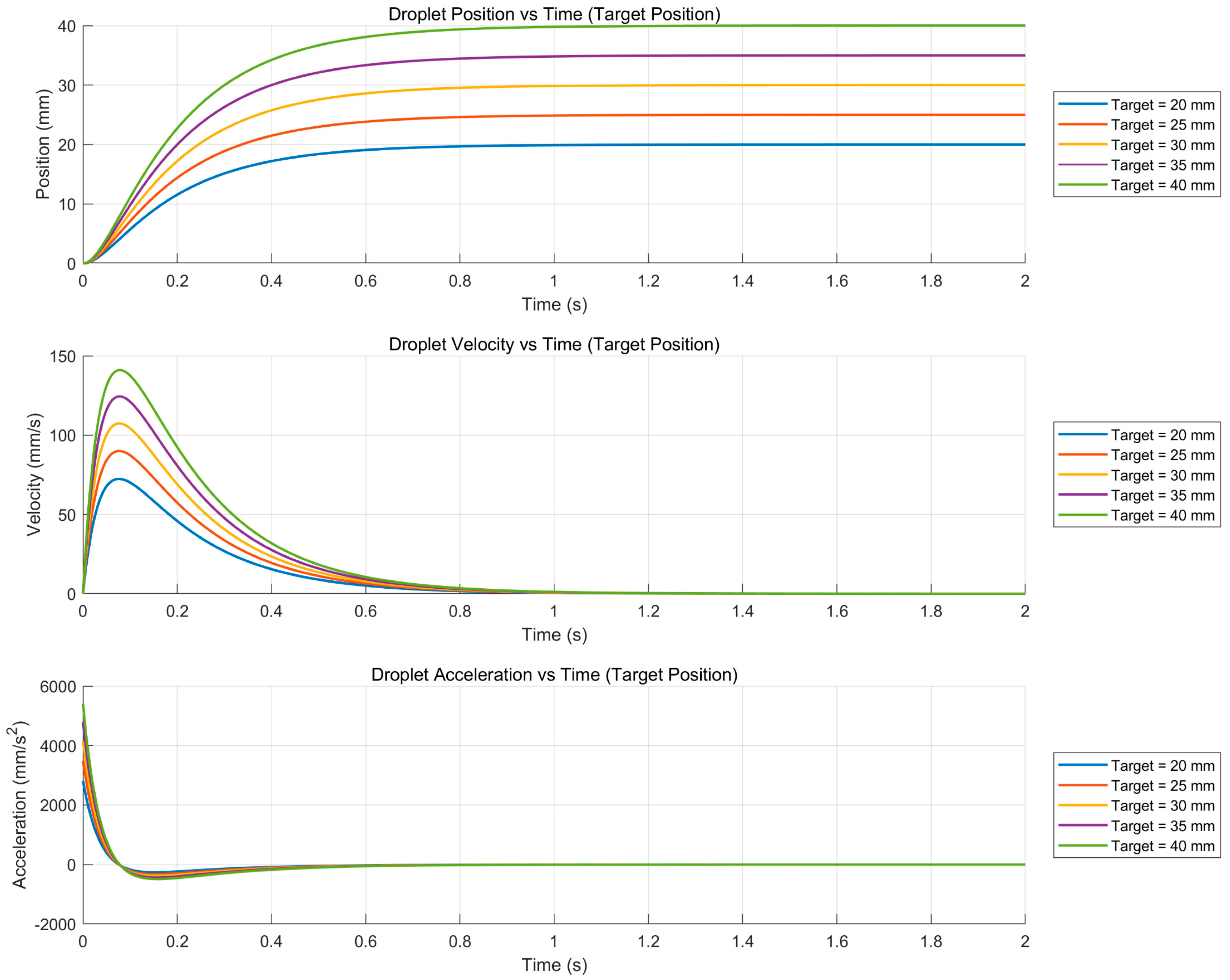
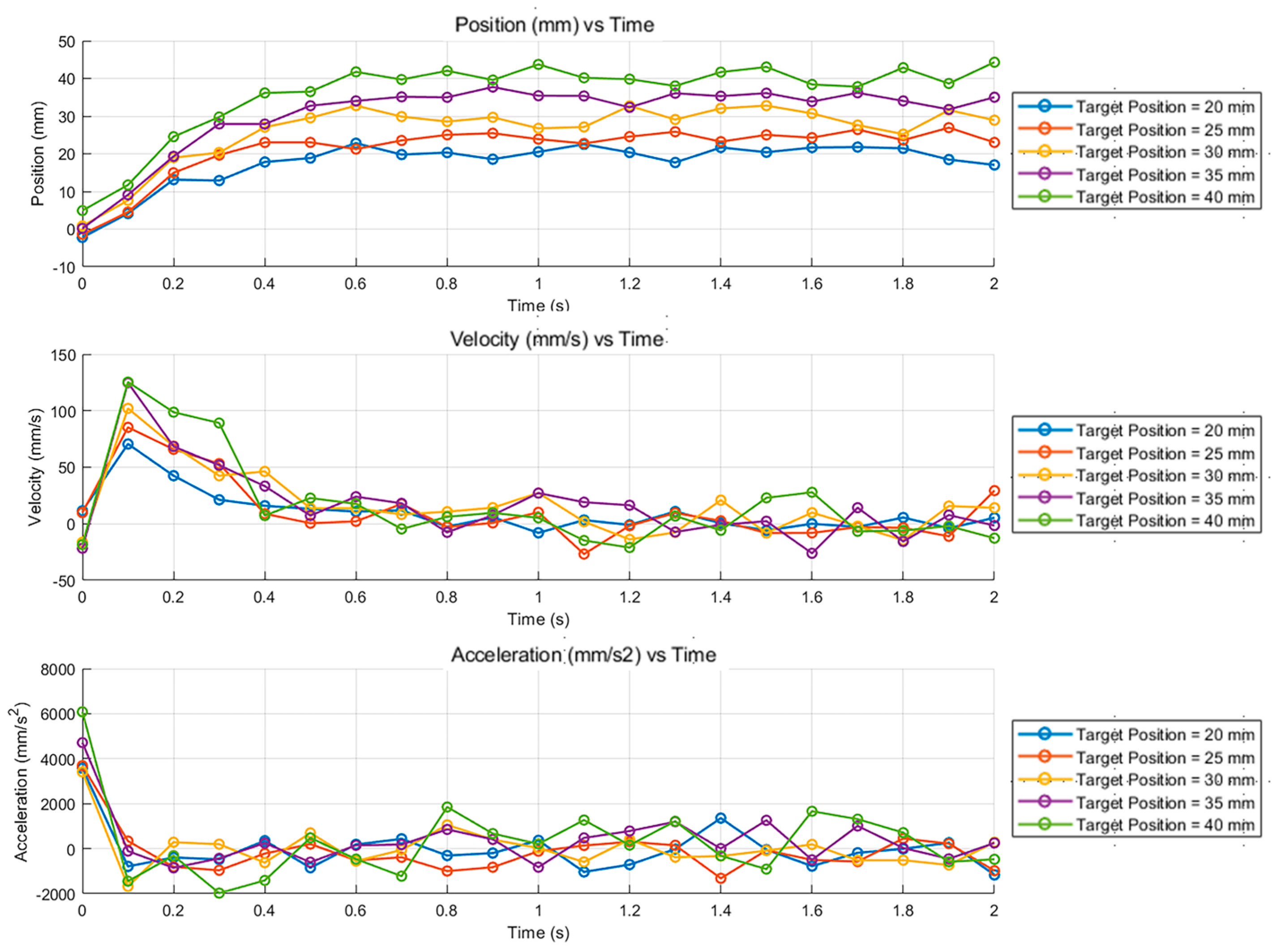
Figure 5 illustrates the dynamic response of a liquid metal droplet under varying target positions ( 20   m m ,   25   m m ,   30   m m ,   35   m m , and 40 mm), highlighting the temporal evolution of position, velocity, and acceleration. The analysis reveals that the droplet exhibits rapid response and high-precision control across all target positions. The position curves demonstrate that the droplet swiftly approaches the target position and stabilizes, with longer response times observed for larger target distances. However, the droplet consistently reaches the desired position with remarkable accuracy. The velocity and acceleration curves further elucidate the droplet’s dynamic behavior: the droplet accelerates rapidly at the initial stage, decelerates promptly as it nears the target, and eventually stabilizes with zero velocity and negligible acceleration. This dynamic trajectory underscores the control system’s ability to effectively regulate the droplet’s motion, ensuring precise localization.
As the target position increases, the peak velocity and acceleration also rise, reflecting the greater force required for the droplet to achieve rapid response over longer distances. This trend highlights the adaptability and stability of the control system. The results demonstrate the system’s superior performance in both dynamic and steady-state control, offering theoretical insights and practical guidance for the motion control of liquid metal droplets in abrasive fluids. These findings are particularly significant for applications aimed at achieving precision machining and advancing technologies in microfluidics and flexible electronics.
Figure 6 presents the experimental results for the motion of gallium-based liquid metal droplets under various target positions (20, 25, 30, 35, and 40 mm). The experimental trajectories clearly demonstrate that the droplets achieve their designated target positions with high accuracy and minimal overshoot. For direct comparison and validation, these results are juxtaposed with the simulation data (see Figure 5). Notably, both experimental and simulated trajectories exhibit rapid convergence during the initial phase (0–0.5 s), followed by stable and nearly oscillation-free settling. The overall agreement in trend between the experimental data and model predictions further confirms the effectiveness and reliability of the proposed control strategy for achieving precise multi-target positioning.
It should be noted that, compared to the simulation, the experimental velocity and acceleration profiles show minor fluctuations. These small oscillations are primarily attributable to unavoidable experimental noise, physical limitations of the actuators, and delays in image acquisition and feedback control. Such minor deviations are typical in practical systems and do not compromise the overall stability or positioning accuracy.

3.2. Motion Response of Liquid Metal Droplets at Different Particle Sizes and Concentrations

Figure 7 illustrates the dynamic behavior of liquid metal droplets under varying particle sizes ( d p = 100   μ m to 300   μ m ) and concentrations ( C p = 2 % to 10 % ). Across all parameter combinations, the droplet accurately reaches the target position ( 20   m m ) with minimal overshoot and consistent stabilization. The position profiles indicate robust control system performance, as variations in particle size and concentration have negligible impact on the steady-state behavior.
The velocity and acceleration curves highlight the droplet’s rapid response and controlled deceleration. Slight increases in peak velocity and acceleration are observed with larger particle sizes and higher concentrations, reflecting the need to overcome increased damping effects. However, the overall response trends remain consistent, demonstrating the system’s stability and adaptability to changes in fluid properties.
These findings confirm the control system’s ability to maintain precise and stable droplet manipulation in abrasive fluid environments with varying particle size and concentration. This robustness is critical for applications such as precision machining and microfluidic technologies, where consistent performance is required despite complex fluid conditions.
As depicted in Figure 8, the experiments with varying abrasive fluid parameters (particle sizes of 100–300 μm and concentrations of 2–10%) confirmed the control system’s adaptability to environmental variations. As shown in Figure 11, the velocity and acceleration plots, larger particle sizes and higher concentrations led to marginally increased peak velocities and accelerations. However, the overall motion patterns and stabilization times remained consistent, indicating that the control system effectively mitigates the impact of fluid parameter variations.

3.3. Motion Response of Liquid Metal Droplets at Different Droplet Radii

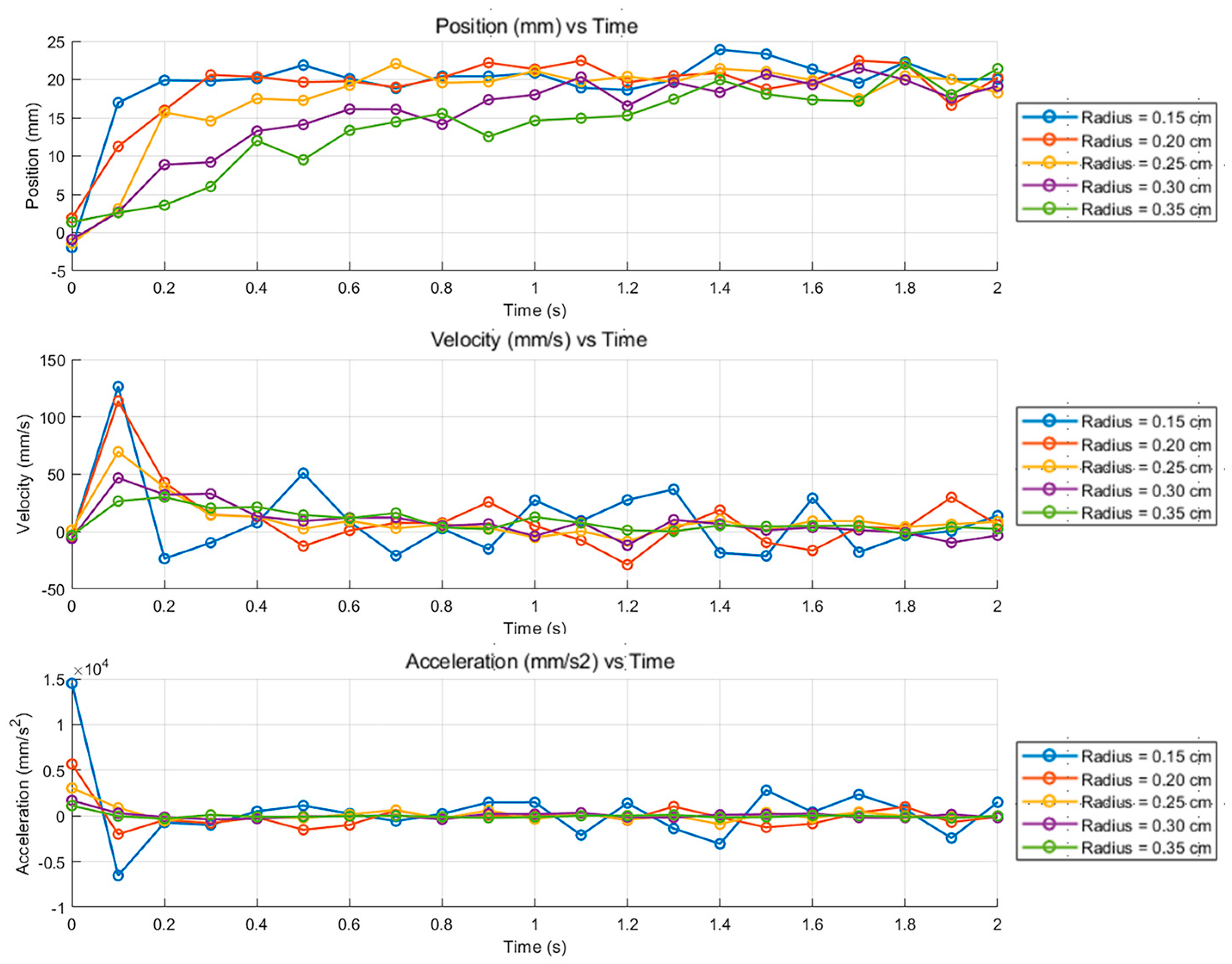
Figure 9 demonstrates the dynamic behavior of liquid metal droplets with varying radii ( r = 0.15   c m , 0.20   c m , 0.25   c m , 0.30   c m , and 0.35 cm), highlighting the evolution of position, velocity, and acceleration over time. The results show that all droplets successfully converge to the target position (20 mm) with high accuracy, regardless of size. Smaller droplets exhibit slightly longer response times and higher peak velocities and accelerations due to increased mass, but the system maintains consistent stabilization with minimal overshoot.
The velocity and acceleration curves indicate that larger droplets require higher momentum and forces to overcome inertia, reflected in slightly elevated peaks. However, the overall trends across all droplet sizes remain consistent, demonstrating the robustness and adaptability of the control system. The system effectively regulates acceleration and deceleration, ensuring smooth and precise droplet positioning.
These findings highlight the control system’s ability to handle droplets of varying sizes without compromising precision or stability. This robustness is essential for applications requiring accurate droplet manipulation, such as in abrasive fluid environments or microfluidic technologies, where size variability is inevitable. The study offers valuable insights into the scalability and reliability of the control process for practical applications.
As shown in Figure 10, for varying droplet radii ( 0.15   c m ,   0.20   c m ,   0.25   c m ,   0.3   c m , and 0.35 cm), experimental results closely matched the simulation (see Figure 7) trends. Smaller droplets exhibited slightly higher velocities and accelerations due to reduced mass, while larger droplets required more time to stabilize at the target position. Despite these differences, the control system maintained stable performance across all conditions, validating its robustness in adapting to different droplet dimensions.
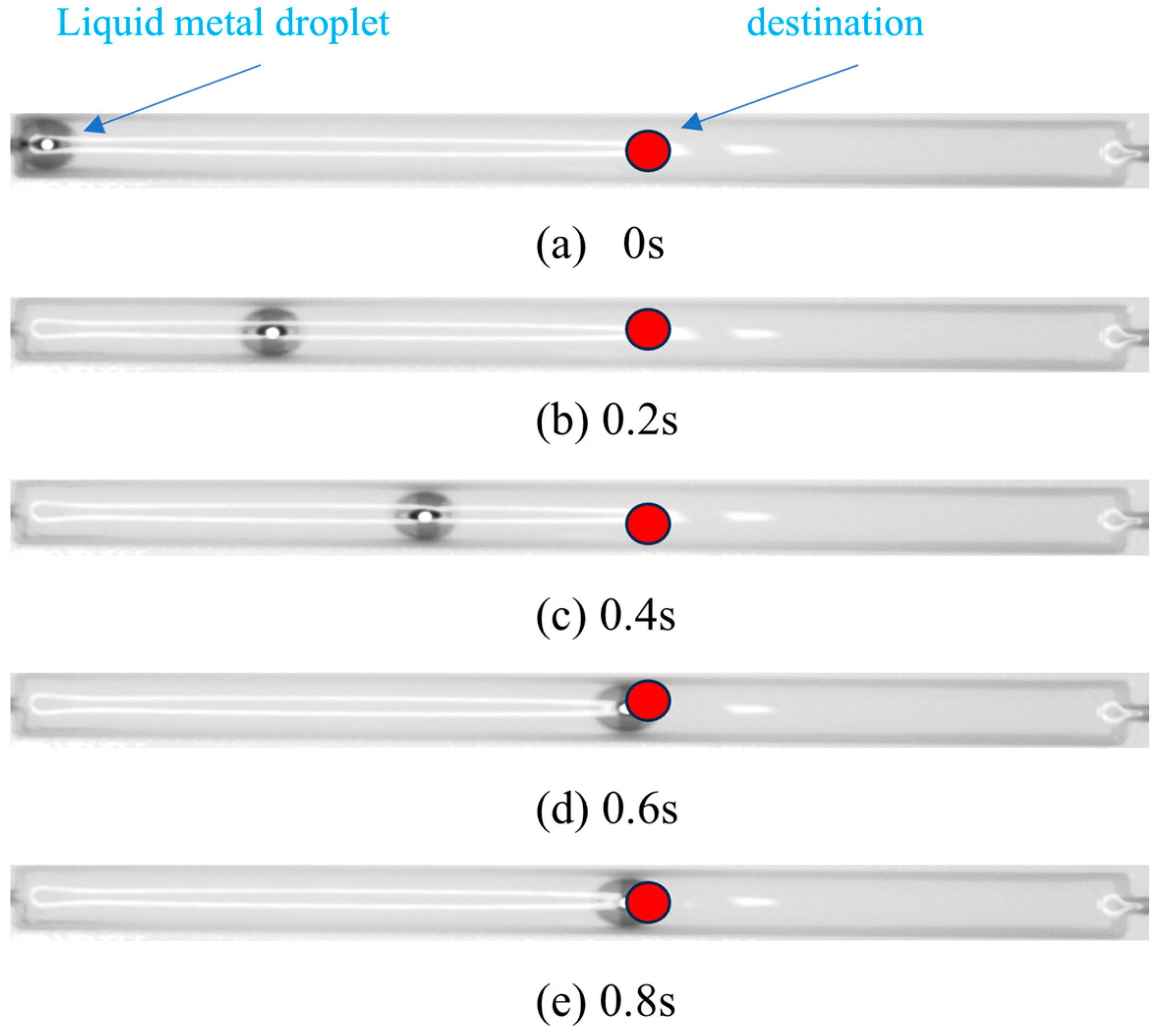
Figure 11 illustrates the droplet manipulation process as captured from experimental video footage. The manipulation sequence depicted in Figure 11a–e was conducted within a rectangular channel. In these images, the liquid metal droplet appears as a spherical object, while its target destination is indicated by a small red circle. Figure 11a presents the initial configuration, and Figure 11b–d display the dynamic manipulation at various time points. Figure 11e demonstrates that the liquid metal droplet successfully reached its designated target. The complete manipulation process can be viewed in the Supplementary Videos S1–S5 uploaded.
The experimental velocity and acceleration profiles aligned with simulation predictions, exhibiting a rapid initial response followed by smooth deceleration. The observed peak values in velocity and acceleration were consistent across experiments and simulations, further validating the control system’s dynamic modeling accuracy. Additionally, the time required for droplets to stabilize at the target position showed minimal deviation between experiments and simulations, supporting the system’s precision and reliability.

4. Conclusions

This study presents a robust control strategy for the precise manipulation of liquid metal droplets in abrasive suspensions. By combining a closed-loop PID controller with real-time feedback, the proposed method dynamically adjusts the applied voltage to achieve high-precision droplet positioning in complex fluid environments. The integration of particle size and concentration into the damping coefficient model enhances the understanding of liquid metal dynamics, offering novel insights into motion control within non-Newtonian fluids.
Simulation and experimental results demonstrate the effectiveness of the control system across varying conditions, including target position, droplet size, and damping properties. The strong agreement between simulation and experimental data further validates the reliability and accuracy of the proposed strategy, confirming its suitability for applications in flexible electronics, microfluidics, and precision machining.
Unlike previous studies, this research systematically addresses the impact of abrasive particle properties on the dynamics of liquid metal droplets, providing a comprehensive approach to motion control. This novel perspective opens new avenues for fine-tuning damping dynamics in complex fluidic systems, enabling enhanced control flexibility for industrial and biomedical applications.
Future work will focus on extending this control framework to three-dimensional fluidic systems and exploring its adaptability to dynamically changing external fields. Additionally, integrating machine learning algorithms could improve real-time optimization and further enhance the system’s responsiveness, broadening its industrial applicability. These advancements have the potential to revolutionize microfluidic devices, biomedical diagnostics, and precision manufacturing systems.

Supplementary Materials

The following supporting information can be downloaded at: https://www.mdpi.com/article/10.3390/act14090456/s1, Video S1: target position-20 mm; Video S2: target position-30 mm; Video S3: target position-40 mm; Video S4: target position-50 mm; Video S5: target position-60 mm.

Author Contributions

Conceptualization, Y.M. and L.Z.; investigation, Y.M., B.F. and K.L.; methodology, Y.M., B.F. and L.Z.; software, B.F. and K.L.; formal analysis, B.F. and L.Z.; writing—original draft preparation, Y.M. and B.F.; writing—review and editing, K.L. and L.Z.; visualization, Y.M. and L.Z.; funding acquisition, L.Z.; supervision, L.Z. All authors have read and agreed to the published version of the manuscript.

Funding

The research work and the APC were funded by the National Natural Science Foundation of China (grant number 52275456).

Data Availability Statement

The raw data supporting the conclusions of this article will be made available by the authors upon request.

Conflicts of Interest

The authors declare no conflicts of interest.

Appendix A. Modeling for Controlling the Motion of a Liquid Metal Droplet

Appendix A.1. The Electrocapillarity of Galinstan

The gallium in the liquid metal droplet (LMD) undergoes oxidation to form G a 2 O 3 , which exhibits poor surface tension characteristics [36]. To remove the oxide layer, an alkaline solution such as NaOH has been employed [37]. Once G a 2 O 3 is completely consumed, NaOH continues to react with Ga, resulting in the formation of the final product, G a 2 ( O H ) 4 , which imparts a negative charge to the surface of the liquid metal droplet (LMD) with a free surface charge density q 0 . According to the DebyeHückel limit, a unipolar volumetric free charge density, contributed by the positive counterions in the NaOH solution, exponentially shields the electric field emanating from the interfacial charge.
When a liquid metal droplet comes into contact with a NaOH solution, the interface between these two immiscible media becomes electrically charged due to various electrochemical processes, such as the adsorption of NaOH solution ions onto the metal surface. This charged interface is known as the electrical double layer (EDL). The thickness of the EDL typically ranges from 10 to   100 Å , depending on factors such as the NaOH solution–metal pair, NaOH solution concentration, electrical conditions, and temperature [38]. The relationship between the interfacial tension and the voltage difference across the electric double layer (EDL) is described by Lippmann’s equation. In this idealized model, the interfacial tension γ decreases proportionally to the square of the applied voltage V , indicating a quadratic dependence of γ on V , a phenomenon known as electrocapillarity. The equation is given as follows [39]:
γ = γ 0 c 2   V 2
where γ is the surface tension, c is the capacitance per unit area of the EDL, V is the electrical potential across the EDL and γ 0 is the maximum value of surface tension at V = 0 . Lippmann’s equation has been verified through numerous experiments with various setups [33,40] and many kinds of other electrolytes [41,42].
The motion of a liquid metal droplet can be induced by a gradient of surface tension along the surface of the liquid metal as a result of the electrocapillary effect [43,44]. This particular phenomenon, known as CEW, is an electrical analogy of the flow motion driven by a thermally induced surface-tension gradient, i.e., the Marangoni effect. Unlike electrophoresis, CEW eliminates the need for charging agents in the electrolyte to maintain a charge in the double layer [39].
In this study, the concept of electric double layer (EDL) behavior under alternating electric fields has been adapted from the work presented [30]. Figure 1 contains schematics that illustrate the CEW. In the figure, a liquid metal droplet is placed in a channel filled with NaOH solution. The EDL completely surrounds the liquid metal and separates it electrically from the electrolyte. The charged state, i.e., charge density, is initially uniform along the interface of the liquid metal droplet and the NaOH solution when no external voltage is applied, as shown in Figure A1a. The EDL can be considered to be a capacitor; thus, the voltage drop of the capacitor is V = q 0 / c , where q 0 and c are the initial surface charge density and capacitance per unit area of the EDL, respectively.
If a voltage is applied between the two graphite electrodes, the surface charge of the LMD will redistribute to reach an electrical equilibrium, as shown in Figure A1b. The electric potential difference on the E D L , V , will also vary. V is greater on the right-hand side than on the left-hand side, as indicated by varying the charge density. This gradient of electric potential across the EDL produces a surface-tension gradient according to Lippmann’s equation. Therefore, the surface tension on the right-hand side is less than that on the left-hand side, and the gradient of surface tension can induce a motion of the liquid metal to the right-hand side of the figure. This motion can also be interpreted as a tendency to minimize surface energy by wetting more area where the surface tension is lower.
The paper establishes the relationship between factors such as the size of LMD and the applied electric field, and the pertinent forces (i.e., the driving force induced by the gradient of surface tension, the viscous friction between the droplet and its surrounding NaOH solution, and the friction between the droplet and the substrate), as shown in Figure A1b. Combining the driving force and resistance, we build a model for illustrating and estimating the motion of LMD in a polymethylmethacrylate (PMMA) channel filled with a NaOH solution.
Figure A1. (a) EDL distribution state without an external electric field; (b) EDL distribution state under an external electric field, reproduced with permission from [30].
Actuators 14 00456 g0a1
After the redistribution of the surface charge on the liquid metal droplet, we assume that the charge within the electrical double layer (EDL) is uniformly distributed across each hemisphere of the droplet. Consequently, the pressure difference across the EDL in each hemisphere can be derived from the Young–Laplace equation [30]:
p = γ 2 r
where p is the pressure difference between the NaOH solution and the LMD, γ is the surface tension and r is the radius of the LMD. Therefore, the pressure difference Δ p between left and right hemispheres of the droplet can be expressed as
Δ p = p L p R = γ L γ R 2 r = 2 Δ γ r
where p L and p R are the pressure differences between the surrounding liquid and the left and right hemispheres of the LMDs, respectively. While γ L and γ R are the surface tensions of the left and right hemispheres, respectively.
Using Equation (A1), the surface tension difference Δ γ can be expressed as
Δ γ = γ L γ R = c 2 V R 2 V L 2
where V L and V R are the potential differences across the EDL of the left and right hemispheres, respectively.
The voltage drop, denoted as Δ φ , between the two ends of the liquid metal droplet (LMD) is induced by the current flowing through both the LMD and the NaOH solution electrolyte layer situated between the LMD and the channel wall. This voltage drop can be estimated as follows:
Δ φ = I R d I 2 r σ A gap   σ V electrode   A current   L 2 r σ A gap   = 2 V electrode   A current   r L A gap  
where I is the current in the circuit, R d is the resistance of the LMD and the thin layer of the NaOH solution between the LMD and the channel wall. σ is the conductivity of the NaOH solution, A g a p is the equivalent cross-sectional area of the NaOH solution between the LMD and the channel wall, V electrode   is the potential applied between the electrodes, L is the total length of the current path, and A current   is the cross-sectional area of the current path. Equation (A4) ignores the resistance of the LMD due to its high conductivity. As such, an approximately equal sign is used. A g a p can be estimated as
A gap   2 r A current   4 3 π r 3 2 r = A current   2 3 π r 2
According to the equation, we observe that a larger r leads to a smaller A g a p . In the absence of an externally applied potential, the electrical double layer (EDL) is initially charged by q 0 , and the resulting voltage due to this charge is V 0 , which can be expressed as V 0 = q 0 / c . The potential difference across the EDL and the absolute voltage can be related as follows:
V L = V 0 Δ φ 2
V R = V 0 + Δ φ 2
By combining Equations (A3), (A6) and (A7), the surface tension difference,   Δ γ , can be calculated as
Δ γ = γ L γ R = c 2 V R 2 V L 2
By combining Equations (A1)–(A8), the pressure difference, Δ p , can be expressed as
Δ p = 2 Δ γ r = 2 q 0 Δ φ r = 4 q 0 A current   V electrode   L A gap     = 4 q 0 A current   A current   2 3 π r 2 V electrode   L
By applying spherical calculus, the driving force induced by the surface tension gradient of the droplet can be derived as follows:
F t = 0 π     0 π     Δ p r 2 s i n θ s i n 2 φ   d θ   d φ = π r 2 Δ p = 4 π q 0 A current   r 2 A current   2 3 π r 2 V electrode   L
where m is the mass of the LMD and is expressed as
m = 4 3 π r 3 ρ
where ρ is the density of the LMD.

Appendix A.2. Dynamic Model

The problem we investigated is formulated as follows. In a liquid metal droplet manipulation system, determine a method to control the current input i , such that the liquid metal droplet can be driven automatically and precisely to any desired position g q in the fluidic channel. Therefore, to control the motion of a liquid metal droplet, we must first derive a dynamic model of the droplet.
When a liquid metal droplet is actuated by an external electrical field to move in channel, the main forces that govern its motion are the surface tension induced driving force F t , the viscous drag force F drag   caused by the NaOH solution, and the friction force F friction   between the liquid metal and the channel, as shown in Figure A2. The dynamics of the liquid metal droplet are then given by
F t F drag   F friction   = m q ¨
where m denotes the mass of the liquid metal droplet, and q denotes its position.
Figure A2. Force analysis of a liquid metal droplet in electrical field.
Actuators 14 00456 g0a2
To establish the movement model of liquid metal accurately, we not only consider the driving force but also the retardation force.
During the motion of LMD, two primary types of retardation forces come into play. One of these is the viscous drag exerted by the surrounding NaOH solution. The viscous force acting on a spherical particle moving through a fluid is described by the well-known Stokes’ formula [45]:
F drag   = 6 π r η v 0
Another one is the friction between the droplet and the substrate, and its expression is as follows:
F friction   = ρ diff   v g β
where ρ diff   is the density difference between the droplet and the NaOH solution, v is the volume of the droplet, g is the gravitational acceleration, and β is the friction coefficient between the droplet and the bottom substrate.

Appendix A.3. The Effect of Abrasive Particles on the Rheological Properties of Fluids
The particle size and concentration of abrasives significantly influence the dynamic viscosity and motion characteristics of liquid metal droplets in solution. To address this, a novel fluid motion control model was developed, incorporating an adaptive damping controller to achieve precise regulation of liquid metal flow in complex dynamic environments. By dynamically adjusting the damping coefficient K 2 d p , C p as a function of abrasive size d p and concentration C p , the proposed model overcomes the limitations of traditional methods, which often assume a constant damping coefficient and neglect the dynamic effects of particle size and concentration on viscous resistance.
The experimentally measured damping coefficient K 2 d p , C p represents the overall viscous characteristics of the solution after the addition of abrasive particles and the adjustment of concentration. It can be decomposed into the three components: the base viscosity of the solution K 2 , 0 ; The incremental effect of particle size d p on viscosity; The incremental effect of solution concentration C p on viscosity.
From a physical perspective, the total damping coefficient results from the combined contributions of multiple factors. Hence, it can be expressed as:
K 2 d p , C p = K 2 , 0 + Δ K 2 d p , C p
where Δ K 2 d p , C p represents the incremental contribution due to particle size and concentration.
Through extensive experimental data and numerical fitting, the influence of abrasive size and concentration on the dynamic viscosity of the liquid metal droplets was quantitatively determined. The resulting dynamic damping model is expressed as:
K 2 d p , C p = K 2 , 0 + α μ d p + β μ C p + γ μ d p 2 + δ μ C p 2
where K 2 , 0 is the baseline damping coefficient, and α μ , β μ , γ μ and δ μ are the coefficients representing the effects of particle size and concentration, respectively, d p and C p represent the particle size and concentration, respectively. To determine the empirical parameters in Equation (A16), an extensive set of experimental data was acquired by systematically varying the particle size ( d p , 1–500 μ m ) and mass fraction ( C p , 1–10%) of abrasive particles. For each parameter combination, the viscosity of the abrasive-laden NaOH solution was measured and averaged over three parallel tests to ensure reproducibility. Nonlinear least squares regression was performed using MATLAB’s lsquarvefit function to fit the proposed viscosity model, where the initial parameter guesses and the model form were set according to the methodology described in the Section 2.
The fitted parameters are as follows:
K 2 , 0 = 0.045   m p a s ,   α μ = 0.0097 ,   β μ = 0.0941 ,   γ μ = 0.0000 ,   δ μ = 0.0093
After performing nonlinear least squares fitting to determine the empirical parameters in Equation (A16), the goodness-of-fit was quantitatively assessed using the coefficient of determination R 2 . The R 2 value serves as a widely used indicator for evaluating how well the model explains the variance in the observed data. In this study, the established viscosity prediction model achieved an R 2 value of 0.9964, indicating excellent agreement between the model and experimental measurements.
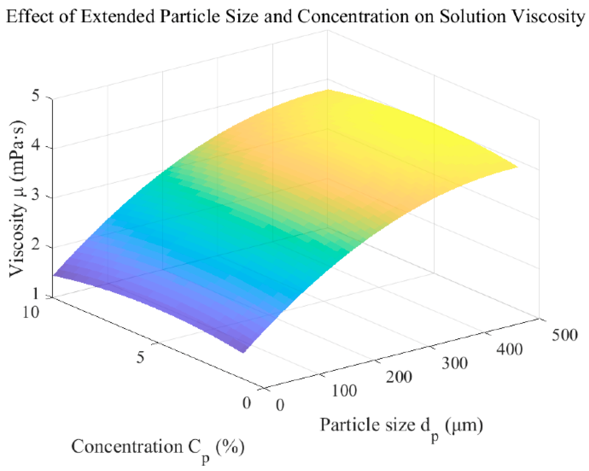
As Figure A3 shows, the influence of particle size d p and concentration C p on the viscosity μ can be analyzed and simplified for modeling purposes. The linear term coefficient for particle size α μ = 0.0097 and the quadratic term coefficient γ μ = 0.0000 are both relatively small, indicating that the effect of particle size on viscosity is primarily linear and overall weak, even across a wide particle size range (e.g., 1   μ m to 500   μ m ). Consequently, the quadratic term for particle size can be omitted, allowing for a simplified model.
Conversely, the concentration C p shows a more significant impact on viscosity, with a notable linear term coefficient β μ = 0.0941 . While the quadratic term coefficient δ μ = 0.0093 is small, it remains necessary for capturing nonlinear effects at high concentrations (approaching 10 % ), where particle–particle interactions or non-uniform particle distribution may slightly mitigate the increase in viscosity. Therefore, the refined viscosity model focuses on the linear terms for both particle size and concentration, while retaining the quadratic term for concentration to account for nonlinear effects in high-concentration regions. The modified viscosity model is expressed as K 2 d p , C p = K 2 , 0 + α μ d p + β μ C p + δ μ C p 2 , effectively balancing simplicity and accuracy for describing the experimental observations.
Figure A3. Effects of particle size d p and concentration C p on the viscosity μ of the solution.
Actuators 14 00456 g0a3
The 3D surface plot demonstrates the increasing trend of viscosity with both particle size and concentration, highlighting their combined influence on the fluid’s rheological properties. Therefore, the refined viscosity model focuses on the linear terms for both particle size and concentration, while retaining the quadratic term for concentration to account for nonlinear effects in high-concentration regions. The modified viscosity model is expressed as:
K 2 d p , C p = 0.045 + 0.0097 d p + 0.0941 C p 0.0093 C p 2
The accuracy of the above fitting equation relies heavily on the experimental data range it is based upon. If the particle size d p and concentration C p exceed the current experimental range (e.g., d p > 500   μ m or C p > 10 % ), the predictions of the fitting model may become unreliable. This limitation arises because the model might fail to capture the significant changes or higher-order effects occurring beyond the tested conditions. Similarly, in regions with sparse data coverage (e.g., d p < 1   μ m or C p < 1 % ), the model may introduce notable bias, reducing its predictive accuracy. Therefore, while the fitting equation provides valuable insights within the tested range, caution is required when extrapolating beyond the experimental boundaries.
This adaptive damping model provides a more accurate representation of the interaction between the abrasive particles and the liquid metal droplets, paving the way for precise motion control in practical applications.

Appendix A.4. Control Design

The motion control of liquid metal droplets in abrasive suspensions is a complex task influenced by factors such as viscous resistance, friction, and external driving forces. This study proposes a closed-loop control strategy based on a PID controller, which dynamically adjusts the applied voltage in response to real-time feedback of the droplet’s position and velocity. By employing this approach, the droplet achieves rapid response and high-precision localization, even under varying environmental conditions. The theoretical foundation of the control system is validated through Lyapunov stability analysis, ensuring robust convergence and stability.
A setpoint controller, inspired by the works of [46,47] was employed to regulate the motion of the liquid metal droplet. The dynamics of the droplet are described by the following equation:
m q ¨ + K 2 q ˙ + K 3 = K 1 I = V
where K 1 = 4 π q 0 A current   r 2 A current   2 3 π r 2 L , K 2 = 6 π r η , K 3 = β ρ diff   , which are all positive constants.
The setpoint controller designed to drive a liquid metal droplet to a desired position within a straight channel is formulated as follows:
V = K p t a n h K r q g q K q q ˙ + K 3
where K p and K r are the positive control gains, K q is the control gain which satisfies the condition of K q > K 2 . The hyperbolic tangent function was used to bound the term K p K r q g q within a certain range K p , K p and avoid generating a large control input V in case the liquid metal droplet is located a long way from the desired g q . When the input voltage is too large, serious electrolysis may appear at the interface between the electrode and the NaOH solution. Gas bubbles generated in the electrolysis reaction may escape into the NaOH solution and hamper the motion of liquid metal. We also noticed some slight electrolysis at the interface between the surface of the liquid metal droplet and the NaOH solution when a large voltage was applied; this also had minor effects on the motion of liquid metal [48]. By substituting the controller (A19) into the dynamics (A18), the closed-loop dynamics is as
m q ¨ + K 2 + K q q ˙ + K p t a n h K r q g q = 0
The damping coefficient K 2 , derived as a function of particle size and concentration, is incorporated into the input-constrained nonlinear set-point controller (A20). By finetuning the control parameters, the precise motion control of the liquid metal droplet is achieved. The corresponding control equation is formulated as follows:
m q ¨ + K 2 d p , C p + K q q ˙ + K p t a n h K r q q g = 0
Theorem A1. 
The liquid metal manipulation system (A12) is globally asymptotically stable under the controller (A19).
Proof. 
Consider a Lyapunov function V 0 as follows:
V = 1 2 m q ˙ 2 + K p K r l n c o s h K r q g q
Taking the derivation of V with respect to time yields
V ˙ = d d t 1 2 m q ˙ 2 + d d t K p K r l n c o s h K r q g q
The simplification of Equation (A23) yields:
V ˙ = m q ˙ q ¨ + K p t a n h K r q g q q ˙
From the system dynamics equation:
m q ¨ = K 2 d p , C p + K q q ˙ K p t a n h K r q g q
Substituting m q ¨ into V ˙ yields:
V ˙ = m q ˙ K 2 d p , C p + K q q ˙ K p t a n h K r q g q + K p t a n h K r q g q q ˙
Expanding and combining like terms, we obtain:
V ˙ = m K 2 d p , C p + K q q ˙ 2
The system’s stability is analyzed using the Lyapunov function approach, as demonstrated by the previously derived Equation (A27).
Where m > 0 is the system mass, which is strictly positive, K 2 d p , C p represents the dynamic damping coefficient, which is influenced by particle size d p and concentration C p , K q > 0 denotes the velocity feedback gain, ensuring a positive combined damping effect, q ˙ is the velocity of the system, and q ˙ 2 0 indicates that the square of the velocity is inherently non-negative.
Given these conditions, the time derivative of the Lyapunov function V ˙ is nonpositive ( V ˙ 0 ), confirming that the system’s energy decays monotonically over time. As the system evolves:
When q ˙ = 0 , it directly follows that V ˙ = 0 .
As q g q and q ˙ 0 , the Lyapunov function reaches its minimum value V = 0 . □

References

  1. Daeneke, T.; Khoshmanesh, K.; Mahmood, N.; De Castro, I.A.; Esrafilzadeh, D.; Barrow, S.J.; Dickey, M.D.; Kalantar-Zadeh, K. Liquid Metals: Fundamentals and Applications in Chemistry. Chem. Soc. Rev. 2018, 47, 4073–4111. [Google Scholar] [CrossRef] [PubMed]
  2. Liu, T.Y.; Sen, P.; Kim, C.J. Characterization of Nontoxic Liquid-Metal Alloy Galinstan for Applications in Microdevices. J. Microelectromech. Syst. 2012, 21, 443–450. [Google Scholar]
  3. Dickey, M.D.; Chiechi, R.C.; Larsen, R.J.; Weiss, E.A.; Weitz, D.A.; Whitesides, G.M. Eutectic Gallium-Indium (EGaIn): A Liquid Metal Alloy for the Formation of Stable Structures in Microchannels at Room Temperature. Adv. Funct. Mater. 2008, 18, 1097–1104. [Google Scholar] [CrossRef]
  4. Monat, C.; Domachuk, P.; Eggleton, B.J. Integrated Optofluidics: A New River of Light. Nat. Photonics 2007, 1, 106–114. [Google Scholar]
  5. Ozbay, E. Plasmonics: Merging Photonics and Electronics at Nanoscale Dimensions. Science 2006, 311, 189–193. [Google Scholar] [CrossRef]
  6. Rogers, J.A.; Someya, T.; Huang, Y. Materials and Mechanics for Stretchable Electronics. Science 2010, 327, 1603–1607. [Google Scholar] [CrossRef]
  7. Schurig, D.; Mock, J.J.; Justice, B.; Cummer, S.A.; Pendry, J.B.; Starr, A.F.; Smith, D.R. Metamaterial Electromagnetic Cloak at Microwave Frequencies. Science 2006, 314, 977–980. [Google Scholar] [CrossRef]
  8. Khoshmanesh, K.; Tang, S.-Y.; Zhu, J.Y.; Schaefer, S.; Mitchell, A.; Kalantar-Zadeh, K.; Dickey, M.D. Liquid Metal Enabled Microfluidics. Lab Chip 2017, 17, 974–993. [Google Scholar]
  9. Mohammed, M.G.; Dickey, M.D. Strain-Controlled Diffraction of Light from Stretchable Liquid Metal Micro-Components. Sens. Actuators Phys. 2013, 193, 246–250. [Google Scholar] [CrossRef]
  10. Siegel, A.C.; Tang, S.K.; Nijhuis, C.A.; Hashimoto, M.; Phillips, S.T.; Dickey, M.D.; Whitesides, G.M. Cofabrication: A Strategy for Building Multicomponent Microsystems. Acc. Chem. Res. 2010, 43, 518–528. [Google Scholar] [CrossRef]
  11. Li, X.; Xie, J.; Tang, S.-Y.; Xu, R.; Li, X.; Li, W.; Zhang, S. A Controllable Untethered Vehicle Driven by Electrically Actuated Liquid Metal Droplets. IEEE Trans. Ind. Inform. 2018, 15, 2535–2543. [Google Scholar] [CrossRef]
  12. Wu, J.; Tang, S.-Y.; Fang, T.; Li, W.; Li, X.; Zhang, S. A Wheeled Robot Driven by a Liquid-Metal Droplet. Adv. Mater. 2018, 30, 1805039. [Google Scholar] [CrossRef] [PubMed]
  13. Ota, H.; Chen, K.; Lin, Y.; Kiriya, D.; Shiraki, H.; Yu, Z.; Ha, T.-J.; Javey, A. Highly Deformable Liquid-State Heterojunction Sensors. Nat. Commun. 2014, 5, 5032. [Google Scholar] [CrossRef]
  14. Sivan, V.; Tang, S.-Y.; O’Mullane, A.P.; Petersen, P.; Eshtiaghi, N.; Kalantar-Zadeh, K.; Mitchell, A. Liquid Metals: Liquid Metal Marbles (Adv. Funct. Mater. 2/2013). Adv. Funct. Mater. 2013, 23, 137. [Google Scholar] [CrossRef]
  15. Rashed Khan, M.; Hayes, G.J.; So, J.-H.; Lazzi, G.; Dickey, M.D. A Frequency Shifting Liquid Metal Antenna with Pressure Responsiveness. Appl. Phys. Lett. 2011, 99, 013501. [Google Scholar] [CrossRef]
  16. So, J.-H.; Thelen, J.; Qusba, A.; Hayes, G.J.; Lazzi, G.; Dickey, M.D. Reversibly Deformable and Mechanically Tunable Fluidic Antennas. Adv. Funct. Mater. 2009, 19, 3632–3637. [Google Scholar] [CrossRef]
  17. Heikenfeld, J.; Drzaic, P.; Yeo, J.-S.; Koch, T. A Critical Review of the Present and Future Prospects for Electronic Paper. J. Soc. Inf. Disp. 2011, 19, 129–156. [Google Scholar] [CrossRef]
  18. Krupenkin, T.; Yang, S.; Mach, P. Tunable Liquid Microlens. Appl. Phys. Lett. 2003, 82, 316–318. [Google Scholar] [CrossRef]
  19. Chen, S.; Wang, H.-Z.; Liu, T.-Y.; Liu, J. Liquid Metal Smart Materials toward Soft Robotics. Adv. Intell. Syst. 2023, 5, 2200375. [Google Scholar] [CrossRef]
  20. Ding, Y.; Zeng, M.; Fu, L. Surface Chemistry of Gallium-Based Liquid Metals. Matter 2020, 3, 1477–1506. [Google Scholar] [CrossRef]
  21. Ma, Y.; Feng, B.; Li, K.; Zhang, L. Application of Liquid Metal Driven-Abrasive Flow to Material Removal for the Inner Surface of Channel. Powder Technol. 2025, 452, 120487. [Google Scholar] [CrossRef]
  22. Li, F.; Kuang, S.; Li, X.; Shu, J.; Li, W.; Tang, S.-Y.; Zhang, S. Magnetically-and Electrically-controllable Functional Liquid Metal Droplets. Adv. Mater. Technol. 2019, 4, 1800694. [Google Scholar] [CrossRef]
  23. Tang, S.-Y.; Sivan, V.; Khoshmanesh, K.; O’Mullane, A.P.; Tang, X.; Gol, B.; Eshtiaghi, N.; Lieder, F.; Petersen, P.; Mitchell, A. Electrochemically Induced Actuation of Liquid Metal Marbles. Nanoscale 2013, 5, 5949–5957. [Google Scholar] [CrossRef] [PubMed]
  24. Jeon, J.; Lee, J.-B.; Chung, S.K.; Kim, D. On-Demand Magnetic Manipulation of Liquid Metal in Microfluidic Channels for Electrical Switching Applications. Lab Chip 2017, 17, 128–133. [Google Scholar] [CrossRef]
  25. Shu, J.; Tang, S.-Y.; Feng, Z.; Li, W.; Li, X.; Zhang, S. Unconventional Locomotion of Liquid Metal Droplets Driven by Magnetic Fields. Soft Matter 2018, 14, 7113–7118. [Google Scholar] [CrossRef] [PubMed]
  26. Gough, R.C.; Morishita, A.M.; Dang, J.H.; Moorefield, M.R.; Shiroma, W.A.; Ohta, A.T. Rapid Electrocapillary Deformation of Liquid Metal with Reversible Shape Retention. Micro Nano Syst. Lett. 2015, 3, 4. [Google Scholar] [CrossRef]
  27. Zhang, J.; Yao, Y.; Sheng, L.; Liu, J. Self-fueled Biomimetic Liquid Metal Mollusk. Adv. Mater. 2015, 27, 2648–2655. [Google Scholar] [CrossRef]
  28. Tang, X.; Tang, S.-Y.; Sivan, V.; Zhang, W.; Mitchell, A.; Kalantar-Zadeh, K.; Khoshmanesh, K. Photochemically Induced Motion of Liquid Metal Marbles. Appl. Phys. Lett. 2013, 103, 174104. [Google Scholar] [CrossRef]
  29. Zavabeti, A.; Daeneke, T.; Chrimes, A.F.; O’Mullane, A.P.; Zhen Ou, J.; Mitchell, A.; Khoshmanesh, K.; Kalantar-Zadeh, K. Ionic Imbalance Induced Self-Propulsion of Liquid Metals. Nat. Commun. 2016, 7, 12402. [Google Scholar] [CrossRef]
  30. Yang, X.; Tan, S.; Yuan, B.; Liu, J. Alternating Electric Field Actuated Oscillating Behavior of Liquid Metal and Its Application. Sci. China Technol. Sci. 2016, 59, 597–603. [Google Scholar] [CrossRef]
  31. Lee, J.; Kim, C.-J. Surface-Tension-Driven Microactuation Based on Continuous Electrowetting. J. Microelectromech. Syst. 2000, 9, 171–180. [Google Scholar] [CrossRef]
  32. Bhagwat, S.; O’Brien, C.; Hamza, A.; Sharma, S.; Rein, C.; Sanjaya, M.; Helmer, D.; Kotz-Helmer, F.; Pezeshkpour, P.; Rapp, B.E. An On-Chip Liquid Metal Plug Generator. Adv. Mater. 2022, 34, 2201469. [Google Scholar] [CrossRef]
  33. Tang, S.-Y.; Khoshmanesh, K.; Sivan, V.; Petersen, P.; O’Mullane, A.P.; Abbott, D.; Mitchell, A.; Kalantar-Zadeh, K. Liquid Metal Enabled Pump. Proc. Natl. Acad. Sci. USA 2014, 111, 3304–3309. [Google Scholar] [CrossRef]
  34. Xie, J.; Li, F.; Kuang, S.; Yang, H.; Li, X.; Tang, S.; Li, W.; Zhang, S. Modeling and Motion Control of a Liquid Metal Droplet in a Fluidic Channel. IEEE/ASME Trans. Mechatron. 2020, 25, 942–950. [Google Scholar] [CrossRef]
  35. Feng, B.; Li, K.; Ma, Y.; Zhang, L. Dynamic Behaviour of Electrically Driven Liquid Metal Droplets in Abrasive Particle Suspensions. Phys. Chem. Chem. Phys. 2025, 27, 14999–15008. [Google Scholar] [CrossRef] [PubMed]
  36. Scharmann, F.; Cherkashinin, G.; Breternitz, V.; Knedlik, C.; Hartung, G.; Weber, T.; Schaefer, J.A. Viscosity Effect on GaInSn Studied by XPS. Surf. Interface Anal. 2004, 36, 981–985. [Google Scholar] [CrossRef]
  37. Gao, Y.; Liu, J. Gallium-Based Thermal Interface Material with High Compliance and Wettability. Appl. Phys. A 2012, 107, 701–708. [Google Scholar] [CrossRef]
  38. Bockris, J.O. Modern Electrochemistry: An Introduction to an Interdisciplinary Area; Springer: New York, NY, USA, 1971. [Google Scholar]
  39. Beni, G.; Hackwood, S.; Jackel, J.L. Continuous Electrowetting Effect. Appl. Phys. Lett. 1982, 40, 912–914. [Google Scholar] [CrossRef]
  40. Xue, R.; Liu, W.; Jiang, T.; Song, C.; Jiang, H.; Ren, Y. Pumping of Ionic Liquids by Liquid Metal-Enabled Electrocapillary Flow under DC-Biased AC Forcing. Adv. Mater. Interfaces 2020, 7, 2000345. [Google Scholar] [CrossRef]
  41. Handschuh-Wang, S.; Chen, Y.; Zhu, L.; Gan, T.; Zhou, X. Electric Actuation of Liquid Metal Droplets in Acidified Aqueous Electrolyte. Langmuir 2019, 35, 372–381. [Google Scholar] [CrossRef]
  42. Hu, Q.; Jiang, T.; Jiang, H. Versatile Movements of Liquid Metal Droplet under Electrostatic Actuation in Alkaline Solutions. Materials 2020, 13, 2122. [Google Scholar] [CrossRef]
  43. Wang, M.F.; Jin, M.J.; Jin, X.J.; Zuo, S.G. Modeling of Movement of Liquid Metal Droplets Driven by an Electric Field. Phys. Chem. Chem. Phys. 2017, 19, 18505–18513. [Google Scholar] [CrossRef] [PubMed]
  44. Dacuycuy, S.; Shiroma, W.; Ohta, A. Electrocapillary Actuation of Liquid Metal in Microchannels. Micromachines 2022, 13, 572. [Google Scholar] [CrossRef]
  45. Brinkman, H.C. A Calculation of the Viscous Force Exerted by a Flowing Fluid on a Dense Swarm of Particles. Flow Turbul. Combust. 1949, 1, 27–34. [Google Scholar] [CrossRef]
  46. Cheah, C.C.; Wang, D.Q.; Sun, Y.C. Region-Reaching Control of Robots. IEEE Trans. Robot. 2007, 23, 1260–1264. [Google Scholar] [CrossRef]
  47. Chen, H.; Sun, D. Moving Groups of Microparticles into Array with a Robot–Tweezers Manipulation System. IEEE Trans. Robot. 2012, 28, 1069–1080. [Google Scholar] [CrossRef]
  48. Yao, Y.Y.; Liu, J. A Polarized Liquid Metal Worm Squeezing across a Localized Irregular Gap. RSC Adv. 2017, 7, 11049–11056. [Google Scholar] [CrossRef]
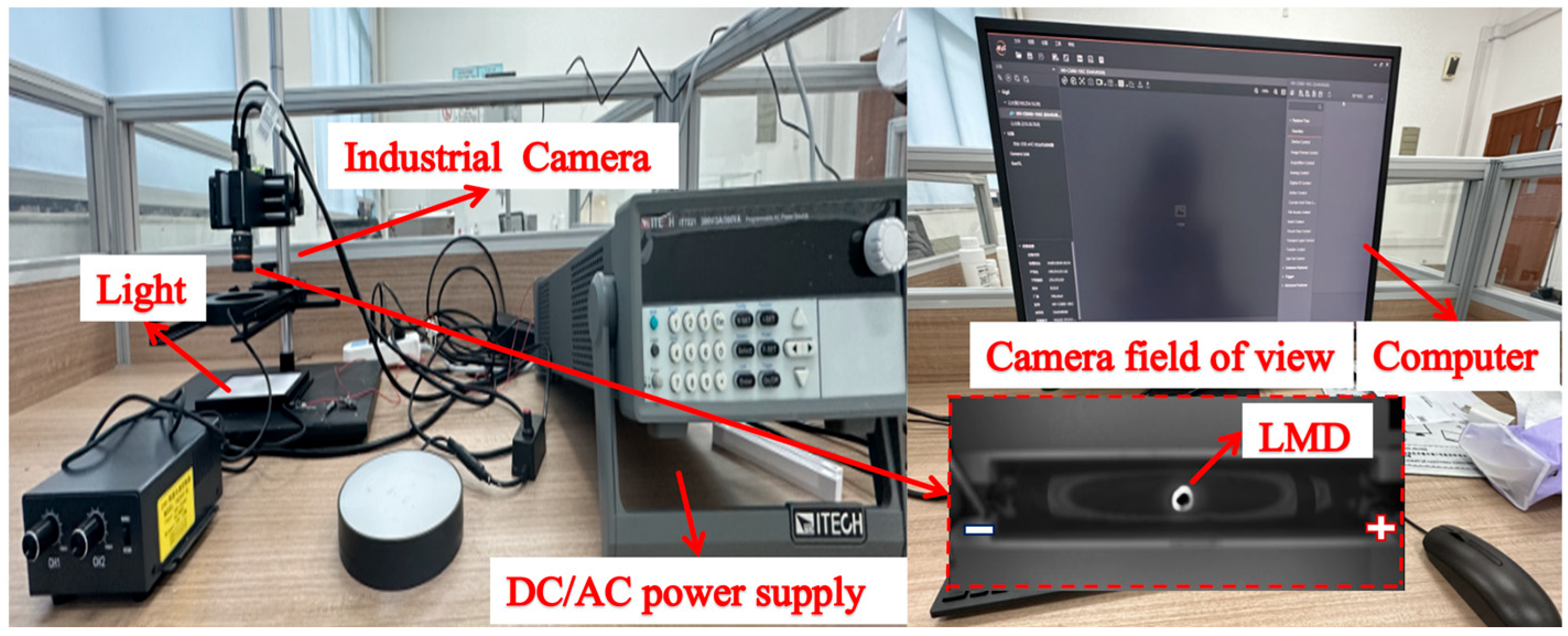
Figure 1. Photo of the liquid metal droplet manipulation system.
Actuators 14 00456 g001
Figure 2. Schematic of the hybrid control framework for the precise manipulation of liquid metal droplet dynamics, including vision feedback, AC/DC power supply, and real-time computer control.
Actuators 14 00456 g002
Figure 3. Photograph of the actual experimental channel and setup, showing the PMMA channels with graphite electrodes and a gallium-based liquid metal droplet positioned.
Actuators 14 00456 g003
Figure 4. Schematic diagram of the high-resolution voltage output strategy.
Actuators 14 00456 g004
Figure 5. Dynamic response of liquid metal droplets under varying target positions ( 20   m m ,   25   m m ,   30 m m ,   35   m m , and 40 mm), showing the evolution of position, velocity, and acceleration over time.
Actuators 14 00456 g005
Figure 6. Experimental results showing the dynamic response of liquid metal droplet under varying target positions ( 20   m m , 25   m m , 30   m m , 35   m m , and 40 mm).
Actuators 14 00456 g006
Figure 7. Dynamic behavior of liquid metal droplets under varying particle size d p and concentration ( C p ) combinations: d p = 100   μ m ,   C p = 2 % ,   d p = 150   μ m ,   C p = 4 % , ( d p = 200   μ m ,   C p = 6 % ), ( d p = 250   μ m ,   C p = 8 % ), and ( d p = 300   μ m ,   C p = 10 % ). The plots show the evolution of position, velocity, and acceleration over time.
Actuators 14 00456 g007
Figure 8. Experimental results comparing the droplet’s motion characteristics with varying particle sizes ( 100   μ m , 150   μ m , 200   μ m , 250   μ m , and 300   μ m ) and concentrations ( 2 % , 4 % , 6 % , 8 % , and 10 % ).
Actuators 14 00456 g008
Figure 9. Dynamic response of liquid metal droplets with varying radii ( r = 1.5   m m , 2.0   m m , 2.5   m m , 3.0   m m , and 3.5 mm). The plots show the evolution of position, velocity, and acceleration over time.
Actuators 14 00456 g009
Figure 10. Experimental results illustrating the impact of different droplet radii (0.15 cm, 0.20 cm, 0.25 cm, 0.30 cm, and 0.35 cm) on the droplet’s dynamic behavior.
Actuators 14 00456 g010
Figure 11. Liquid metal droplet manipulation process in rectangular channel.
Actuators 14 00456 g011
Disclaimer/Publisher’s Note: The statements, opinions and data contained in all publications are solely those of the individual author(s) and contributor(s) and not of MDPI and/or the editor(s). MDPI and/or the editor(s) disclaim responsibility for any injury to people or property resulting from any ideas, methods, instructions or products referred to in the content.