1. Introduction
Robots and humans have traditionally been kept isolated due to safety concerns. Only in recent years, collaborative robots (cobots) that can work alongside humans have come to market. This has raised an important problem in Human–Robot Interaction which is the reduction of damage during an impact between a robot and a human being. This problem is critical because humans could suffer serious or even fatal injuries if they received a rigid impact from a robot. Furthermore, the impact could cause serious damage to the mechanical adjustment of the robot. A practical solution to reduce these negative consequences is for manipulators to have variable stiffness.
Variable stiffness in robot arms can be implemented through two strategies: Variable-Stiffness Joints (VSJ) and Variable-Stiffness Links (VSL). VSJ has been extensively investigated in human–robot interaction [
1,
2,
3], while VSL has been recently studied [
4,
5,
6]. In addition, one of the applications of variable stiffness in robotics is the attenuation of collisions between human beings and robots. There are two strategies in this regard. The first approach is active compliance, which consists of detecting the collision and then controlling the stiffness of the arm appropriately [
7,
8]. This strategy involves using various types of sensors to detect the collision [
9], and actuation mechanisms to dynamically respond to the impact. The second strategy is passive compliance, which consists of mechanical components that absorb the excessive collision force. Examples of passive components are springs, dampers, and soft covers. Passive compliance provides fast and reliable responses to collisions, but the response cannot be controlled during the impact because the stiffness of these components is usually tuned before the operation of the robot, or it is a permanent property of the component [
4,
5].
Various technologies have been studied to modulate the stiffness of members in the robotic fields of Medical Devices [
10] and Soft Robotics [
11]. Laminar Jamming (LJ) is one of these technologies that has been investigated since 2002 [
12]. In addition, LJ structures have been implemented to build VSLs [
13,
14,
15,
16], which demonstrate a considerable potential to reduce the impact between robot arms and human beings.
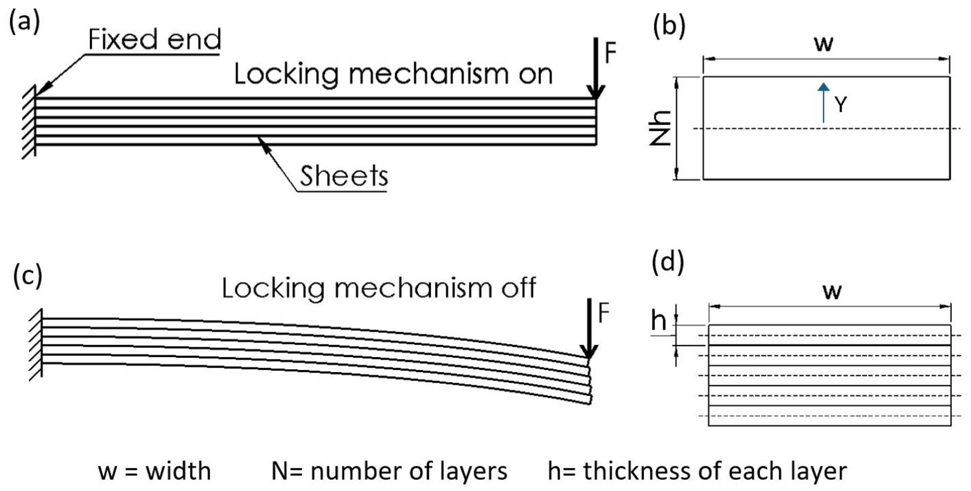
A LJ structure consists of a beam that is made of a stack of thin sheets and a mechanism to lock/unlock the sheets. When the mechanism locks the sheets, the bending stiffness is high and the whole beam resembles the behavior of a rigid member. When the mechanism unlocks the layers, sliding can occur between them, the bending stiffness reduces, and the LJ structure becomes flexible.
Figure 1a,b illustrate the rigid and flexible states of a LJ structure that is formed by 5 sheets (
N = 5). It can be observed that, in the flexible state, the layers are not coupled and there is slip between them.
The fundamental phenomenon that allows the variation in bending stiffness of the LJ structure is the change in the area moment of inertia
I. The bending stiffness
k depends linearly on
I, in the case of a cantilever beam of length
L and Young’s modulus
E, this relation is given by Equation (1) [
18].
Figure 1b,d illustrate the cross-sectional area (
A) of a LJ structure,
w is the width of the beam,
h is the thickness of each layer, and
N is the numbers of layers. When the mechanism locks the layers, they form a solid beam as illustrated in
Figure 1b, all the layers bend around the neutral axis of the stack and the beam has maximum bending stiffness, or in other words, the LJ structure is stiff. The
I of the beam in this case is defined by Equation (2).
When the mechanism unlocks the layers, each individual layer bends around its own neutral axis, the whole beam has the minimum bending stiffness, and the layers slide freely as it can be seen in
Figure 1c. In other words, the beam is in a flexible state. The
I of the beam in this case is defined by Equation (3).
It can be observed in Equation (2), that
I of the LJ structure in the rigid state depends on the number of layers raised to the 3rd power (
). In contrast, Equation (3) shows that
I of the beam in the flexible state depends on the number of layers (
N). The stiffness ratio or the stiffness variation can be calculated by comparing the area moments of inertia in the flexible and rigid state, which yields:
As Equation (4) shows, the stiffness ratio in a LJ structure depends on the number of layers raised to the second power [
12,
17]. This generates, at least in theory, the possibility of obtaining very high stiffness variation by only adding more layers to the beam [
17]. For the case of the LJ presented in
Section 2, the number of sheets is 10 (
N= 10), which implies that the maximum stiffness ratio that could be reached is 100. However, this is a theoretical value because other factors, such as friction and efficacy of the lock/unlock mechanism, would reduce significantly the stiffness ratio that can be achieved.
Common mechanisms to lock/unlock the LJ structures are based on friction, mechanical interference, or miscellaneous principles [
19]. In general, these mechanisms have demonstrated to be effective in achieving the variation of stiffness. The first two principles are relevant for the mechanism proposed in this article.
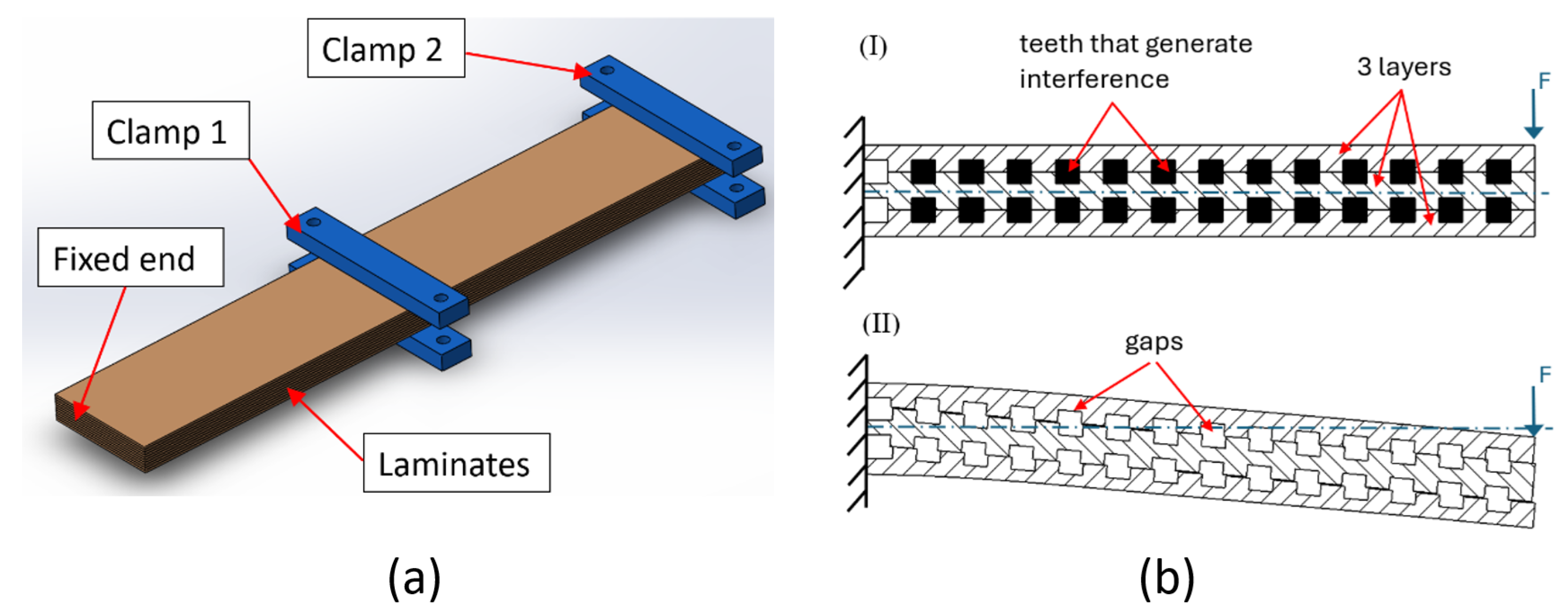
The principle of friction-based mechanisms consists on modifying factors that determine friction forces. One of these friction mechanisms is known as Discrete Laminar Jamming (DLJ), which consists of many variable pressure clamps placed discretely along the LJ structure [
14,
15] as can be seen in
Figure 2a. The clamps apply normal force to the stack of layers in that specific section which increases the friction between the sheets, leading to the locking of the layers and increasing the bending stiffness of the LJ structure.
The principle of mechanical interference consists on preventing the relative slip between the layers. This principle is usually implemented by introducing an object that passes through the layers of the LJ structure. There is an actuator that thrusts the object into the sheets to increase the stiffness and pulls the object out of the layers to reduce the stiffness. The sheets often have a slot or cutout to accommodate the object that goes through them.
Figure 2b illustrates an example of a mechanism based on mechanical interference. The mechanism consists of layers with teeth that are aligned and form gaps between them, as can be seen in
Figure 2b(II). A mechanism driven by Shape Memory Allowy wires [
20], or a mechanism based on electroactive polymers [
21] introduces teeth inside the gaps of the layers. This generates a mechanical interference that prevents slipping between the sheets and, therefore, increases bending stiffness, as
Figure 2b(I) illustrates. The same mechanism can remove the teeth that generate the interference, allowing slip between the layers, which, in turn, generates the minimum bending stiffness, as illustrated in
Figure 2b(II). Intermediate values of bending stiffness can be achieved by varying the location and number of the teeth that are introduced in the gaps along the LJ structure.
In the last years, vacuum pressure has become the predominant lock/unlock mechanism of LJ applied in robots with VSLs. This mechanism consists of an airtight chamber that envelops the sheet stack, and a vacuum pump that applies negative pressure inside the chamber. When the vacuum is activated, atmospheric pressure compresses the chamber and the stack of sheets that is inside. As a result, friction between the layers increases, leading to the locking of the sheets and the corresponding increase in bending stiffness [
22].
The main advantages of LJ with vacuum pressure are the highest speeds of stiffening and destiffening in comparison with other lock/unlock mechanisms [
11,
17], and the possibility to reach stiffness ratios as high as 180 [
23]. However, this mechanism is still too slow to be applied in the reduction of an impact between a human being and a robot arm. For example, a LJ structure with vacuum pressure has a measured time constant about 0.5 s to change its stiffness [
24], which is too slow when taking into account that the damage due to impacts between humans and industrial robotic arms takes about 0.1 s [
25]. Moreover, the transition of LJ structures from the rigid state to the flexible state may not be complete nor immediate, as was demonstrated in experiments where, after each test, the LJ sample was disconnected from the vacuum regulator and flexed multiple times to speed up its return to ambient pressure [
22]. Another problem of this mechanism is the sealing of the airtight chamber because it uses an elastic membrane that could be damaged due to contact or impact against rough edges [
14,
15].
The new lock/unlock mechanism for LJ proposed in this work has the prospect of achieving a fast change from high stiffness to low stiffness in order to be useful during an impact between a human being and a robot link. Furthermore, this mechanism does not have the sealing limitations of LJ with vacuum pressure.
This article is a revised and expanded version of a paper entitled “Laminar Jamming with Trapezoidal Pin Mechanism for Variable Stiffness Robotic Arms” [
26], which was presented at ROBIO 2022, Xishuangbanna, China, and the paper entitled “A Novel Multi-Layer Beam Mechanism for Variable Stiffness Robotic Arms” [
27], which was presented at ACRA 2021, Melbourne, Australia. This article presents a novel mechanism to lock/unlock a LJ structure, as well as experiments and finite element (FE) simulations that were conducted to evaluate the performance of this new mechanism as a potential method to modulate the stiffness of a robot link arm. This article is organized as follows: the concept is presented in
Section 2;
Section 3 describes the experiments and their result;
Section 4 discusses the finite element simulations and their results;
Section 5 describes the computational studies; and conclusions and future work are provided in
Section 6.
2. Trapezoidal Pin Mechanism
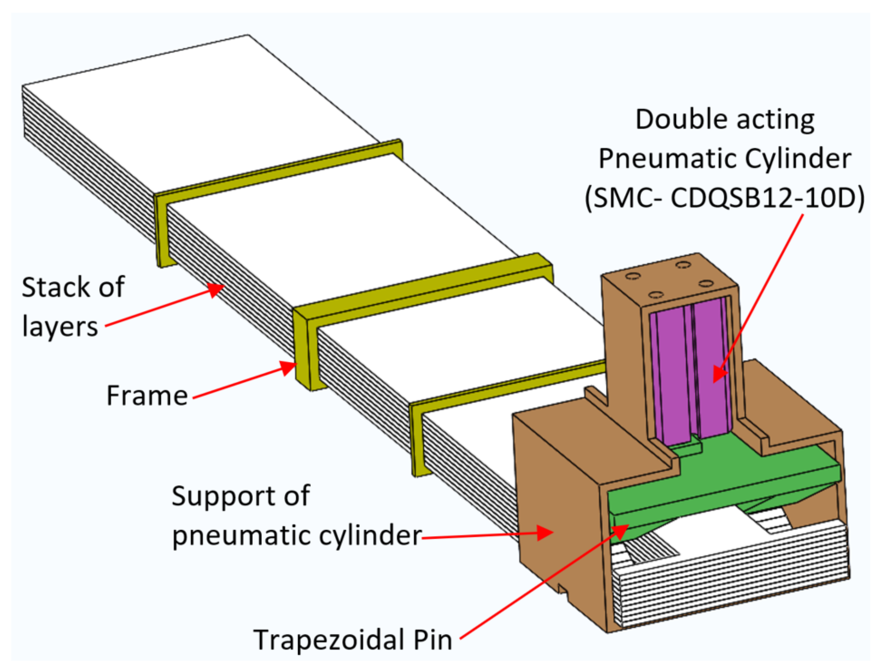
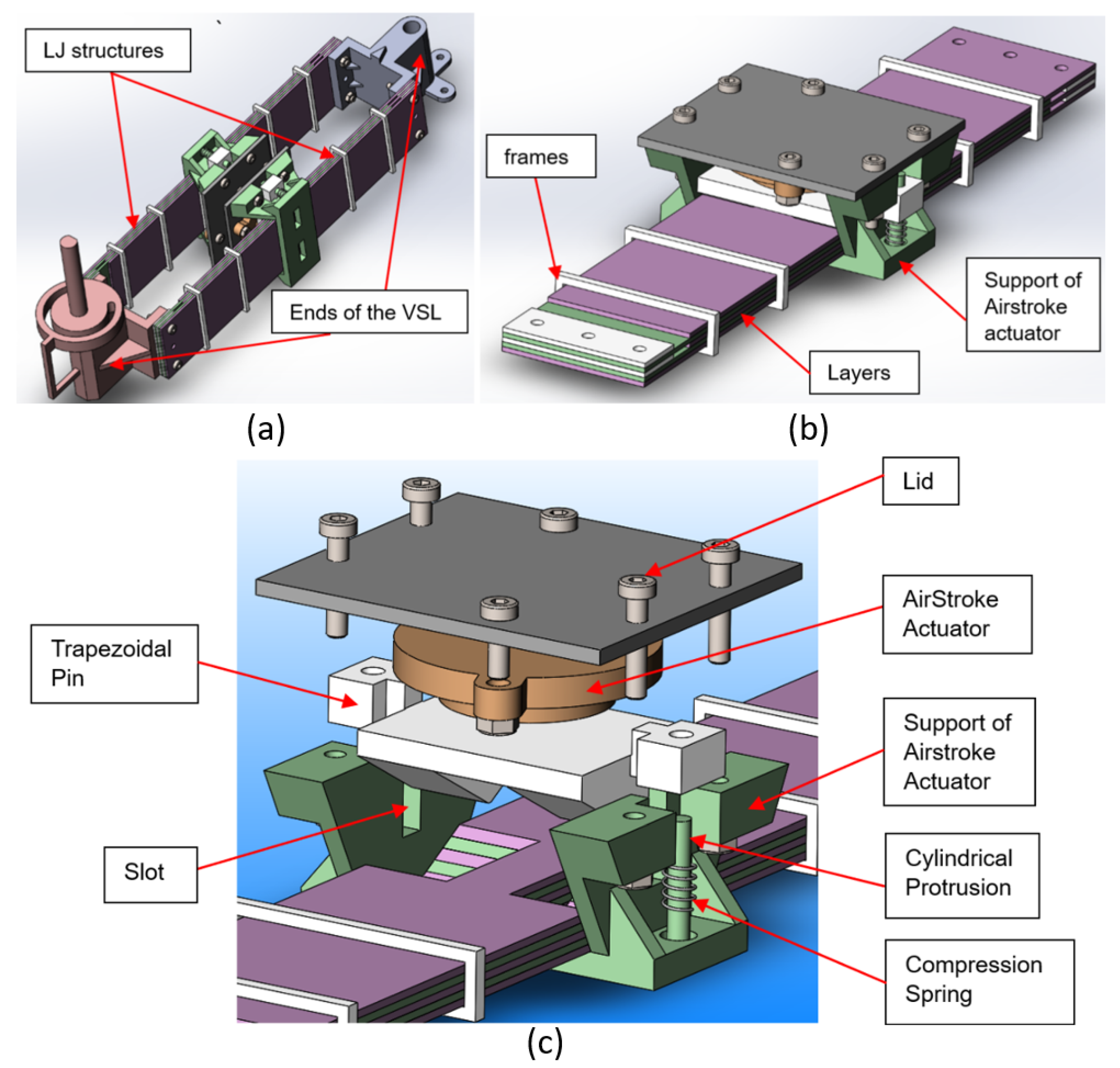
The lock/unlock mechanism of LJ structures presented in this work is based on a combination of the principles of mechanical interference and friction. The components of this mechanism can be seen in
Figure 3. It consists of a trapezoidal pin that is coupled to the rod of a pneumatic actuator.
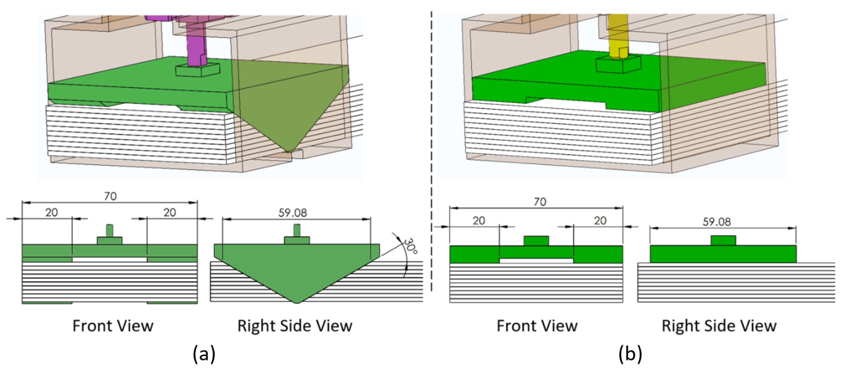
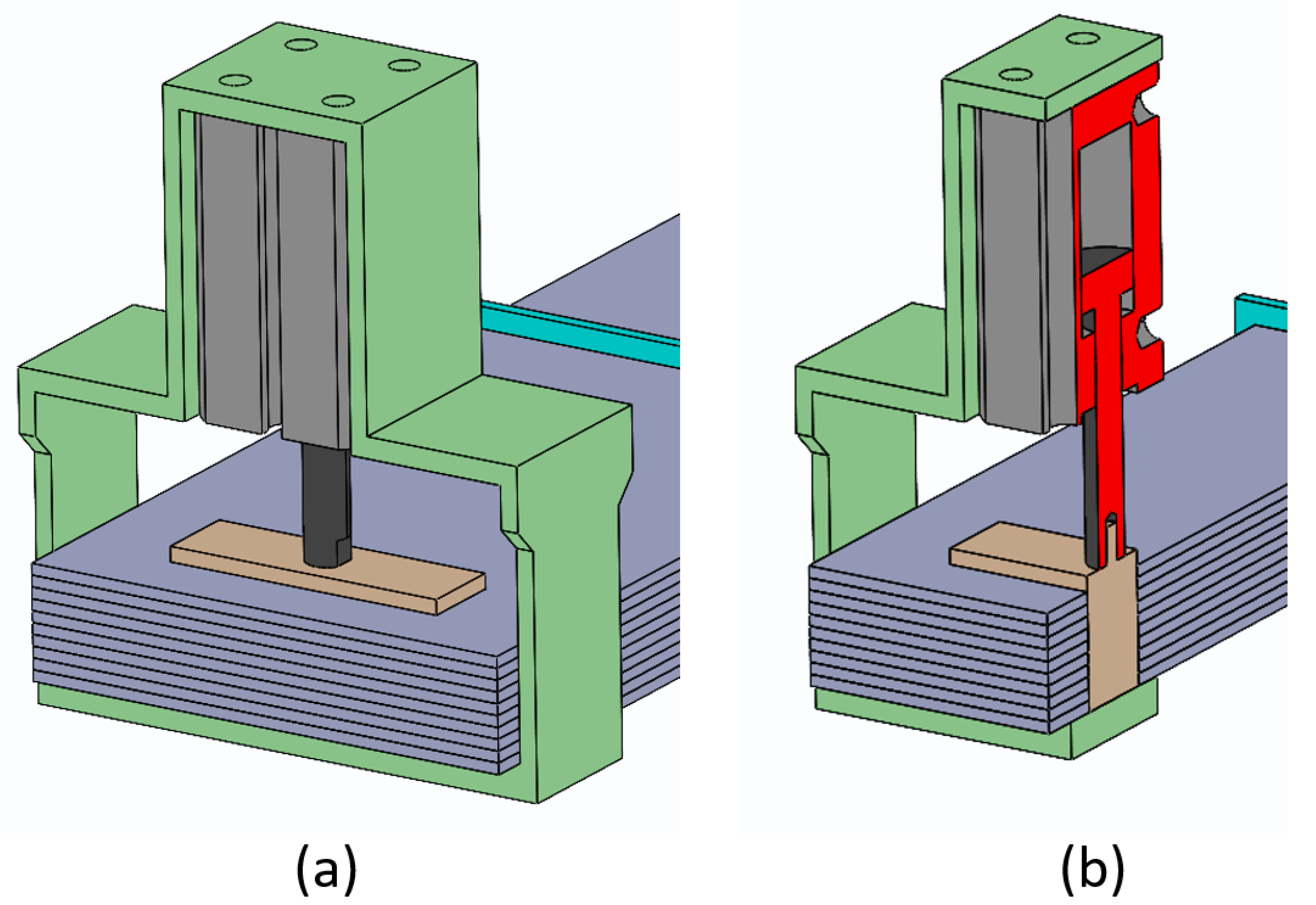
Figure 4a shows that when the pneumatic cylinder is pressurized, the trapezoidal pin is thrust into the trapezoidal slots formed in the sheets. The trapezoidal pin compresses the layers and raises the friction force between them in that section. The fact that the pin comes in and out of the LJ structure produces mechanical interference. When the trapezoidal pin is disengaged, the LJ structure has the lowest stiffness (
Figure 3). When the trapezoidal pin is engaged, the stiffness of the LJ structure depends on the force that is applied to the pin, which in turn depends on the air pressure in the pneumatic actuator (
Figure 4a).
When the LJ structure is bent, the slip between the layers pushes the pin out due to its trapezoidal shape. This phenomenon, which is described in
Section 5.4, makes a fast transition from a high stiffness state to a low stiffness state easier. In contrast, a straight pin or cylindrical pin tends to get stuck by the layers when the LJ structure is deformed by bending as was noticed in preliminary qualitative tests.
The LJ with trapezoidal pin was compared to an LJ with a flat clamp that is illustrated in
Figure 4b. Both LJ structures have the same parts and dimensions and were simulated and tested under the same conditions. The concept of the flat clamp is similar to the concept of DLJ. The main difference between these two LJ mechanisms is the width of the clamp. The clamps in DLJ have the same width of the stack of layers and make contact with them along the whole width. Instead, the flat clamp presented in this article has two contact areas whose width (20 mm) and length (59.08 mm) in the horizontal plane are identical to the projected contact areas in the trapezoidal pin to enable a fair comparison, as shown in
Figure 4.
2.1. Description of the Components of the LJ
The general characteristics of each component of the proposed LJ mechanism are described as follows.
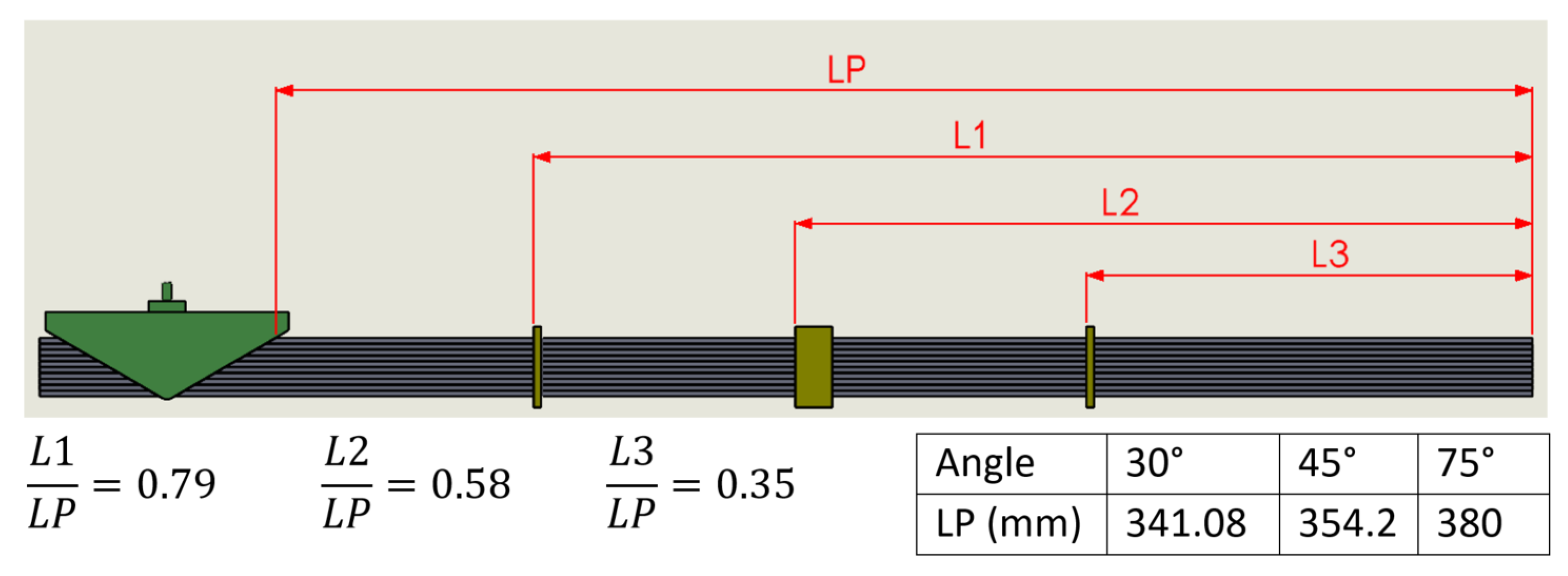
Frames: Three frames were placed along the LJ structure. Their main function is to avoid independent buckling of the sheets by keeping them together in one stack. The frame in the middle is notably longer than the other two frames. This feature was implemented to resemble the DLJ design that has a clamp of similar length in the same position [
14,
15]. The frames do not constrain the relative slipping of the sheets because some of the frames are bonded to the top layer and others to the bottom layer, but none are bonded to both. In addition, a small clearance between the frames and the stack of sheets ensures that they do not apply pressure to the LJ structure.
Layers: The LJ structure has 10 layers made of Acrylonitrile Butadiene Styrene (ABS) plastic with a thickness of 1.5 mm, length of 405 mm, and width of 70 mm. The material has a density of 1030 Kg/m3 and a Young’s Modulus of 180 GPa. Each sheet has a cutout with a different length to accommodate the trapezoidal pin.
Pneumatic Cylinder (SMC-CDQSB12-10D): This double-acting pneumatic cylinder was selected because of its high force per weight output compared to other actuators, such as solenoids. This pneumatic cylinder was manufactured by SMC (Tokyo-Japan).
Trapezoidal Pin: The trapezoidal pin sits in the trapezoidal cutouts of the layers in such a way that it comes into contact with all the layers of the LJS. The pin has two trapezoidal protrusions that come in contact with the stack of layers in two areas that have a width of 20 mm each, as can be seen in
Figure 4. The rod of the pneumatic cylinder is attached to the trapezoidal pin with a threaded connection.
Support of Pneumatic Cylinder: This support, which is attached to the bottom layer with an adhesive, has enough height to let the trapezoidal pin completely emerge from the stack of sheets. Thus, it does not prevent the slip between the sheets.
The trapezoidal pin, the support of the pneumatic cylinder, and the frames were manufactured by 3D printing (fused deposition modeling technology), and the material was polylactic acid (PLA).
2.2. Manufacturing
The layers are the components that require the most work and attention. The external shape of the layers was cut with a saw/router machine in the LJ structure with flat clamp and the LJ structure with the trapezoidal pin. In the case of the LJ structure with flat clamp mechanism, there is no other manufacturing process required.
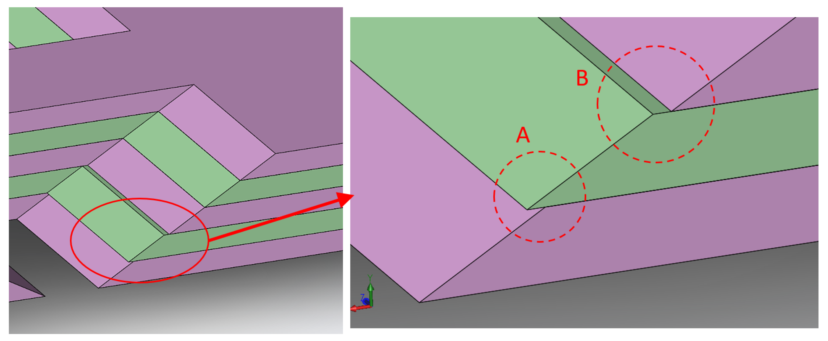
In the case of the LJ structure with the trapezoidal pin mechanism, the machining of trapezoidal cutouts in the layers is a critical task. Milling the trapezoidal slot in each layer separately was not a viable solution since any variation in the machining process of each layer would generate a step or a zig-zag pattern in the trapezoidal slots, as can be seen in
Figure 5, which in turn would generate contact with the trapezoidal pin that occurs only in one specific layer instead of contact occurring in all the layers.
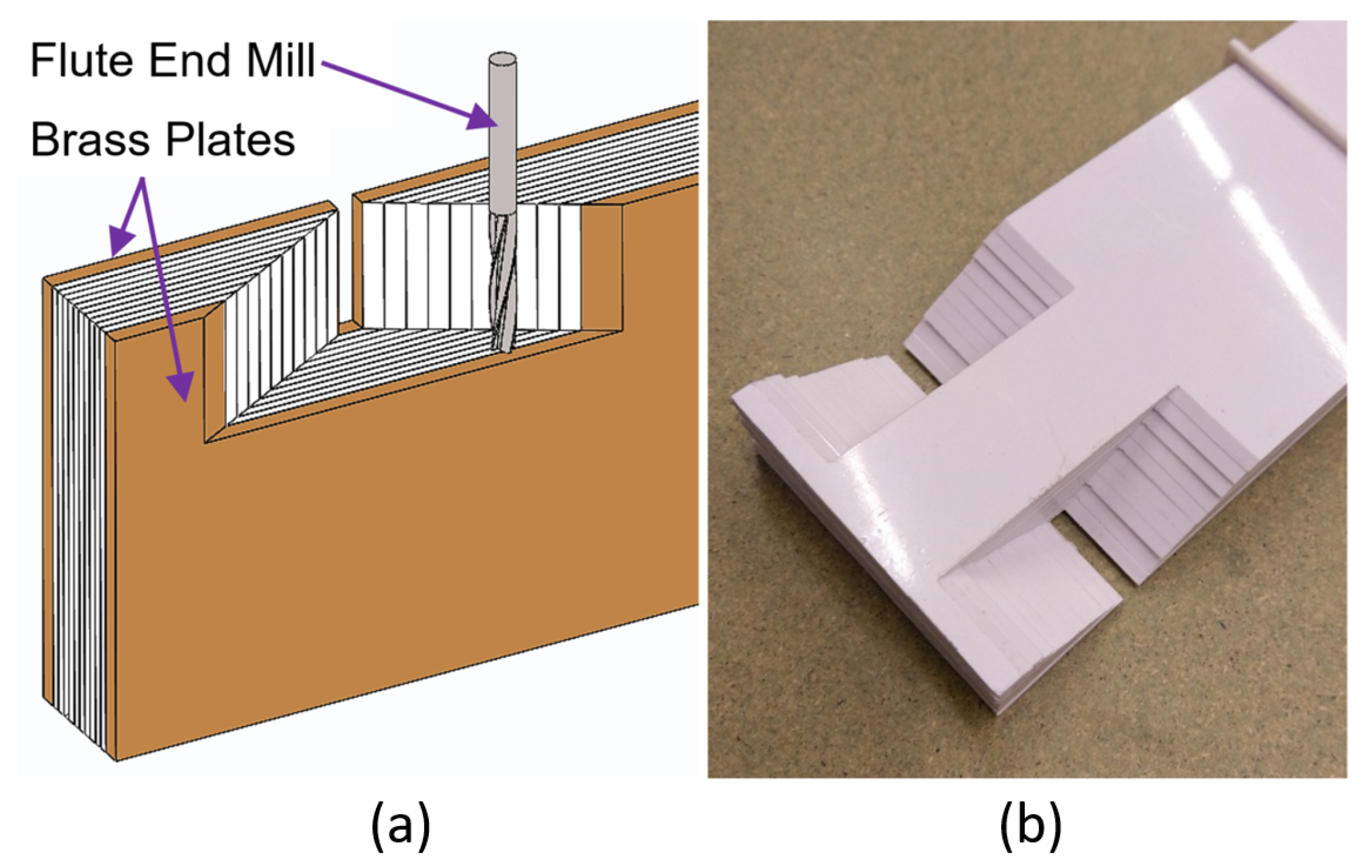
The solution to cut the trapezoidal slot in the LJ structure consisted on machining all the layers at the same time, as can be seen in
Figure 6. A fixture comprising two sacrificial brass plates was implemented to achieve this purpose, and all the layers and the brass plates are joined by bolts on one end of the LS structure. These plates have two functions. First, they keep the sheets together during the machining. Second, it allows to fix the LJ structure on the milling machine or the machining center. As a result, there was no flutter or vibration of the ABS layers when the milling tool cut the trapezoidal slot.
Machining was preferred over laser cutting for layer manufacture because laser machines are not usually able to cut a chamfer since the laser is always perpendicular to the sheets. In addition, laser cutting produces toxic fumes when cutting ABS. Furthermore, machining would be more appropriate for manufacturing the layers in metallic materials, which is one of the directions of future work that is envisioned for LJ structures with a trapezoidal pin mechanism.
3D printing for layer manufacture was not selected due to insufficient dimensional accuracy, rough surface finish, and low repeatability of material and mechanical properties that characterize most of the 3D printing technologies of plastic materials [
28], which does not give the researchers good confidence to replicate the results through experiments or FE simulations.
2.3. Novelty of the Trapezoidal Pin Mechanism
The novelty of the trapezoidal pin mechanism consists of four aspects that were defined according to the Function–Behavior–Structure Model [
29]. The first aspect is its working principle applied to the development of VSLs. The trapezoidal pin mechanism combines the principles of friction force and mechanical interference that were explained in
Section 1. The proposed mechanism is based on the conical pin mechanism that also combines the principles of friction and mechanical interference with the purpose of being applied in VSLs [
27]. Only another LJ structure with the same combination of working principles has been found in the literature, but it was developed for providing variable stiffness in haptic gloves [
30].
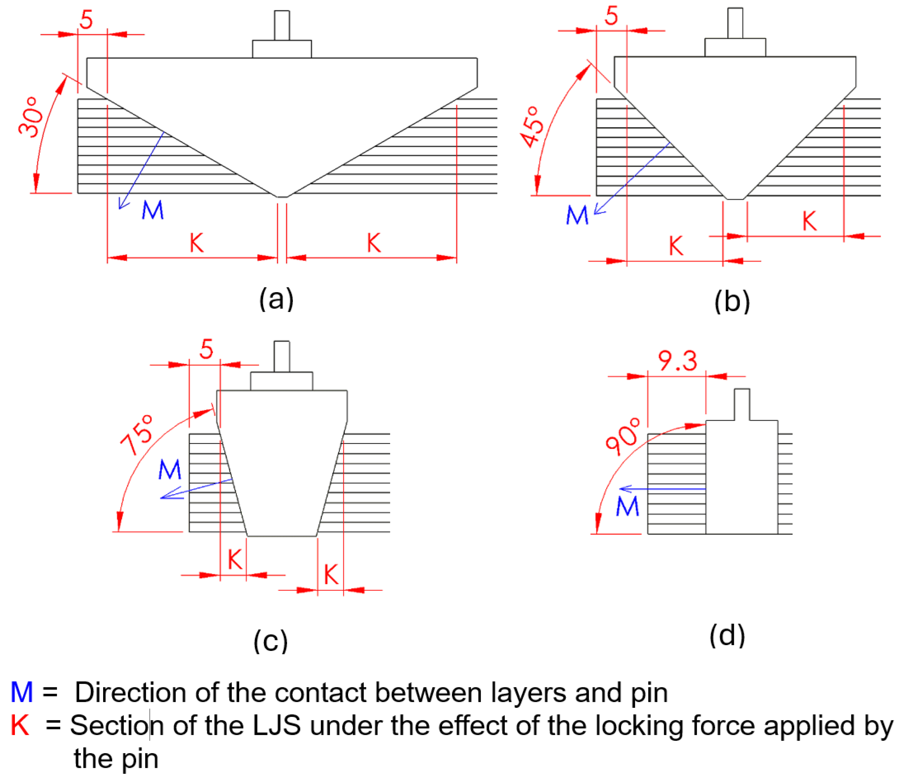
The second novel aspect of the trapezoidal pin mechanism is its structure or design. The combination of the friction principle and the mechanical interference principle occurs in the same structural element, which is the trapezoidal pin, rather than having two separate mechanisms with different working principles placed at different locations along the LJ structure. The trapezoidal pin generates normal friction between the layers and simultaneously interferes mechanically with the layers, preventing their relative slip. The intensity of the effects generated by each principle depends on the angle of the trapezoidal pin, this behavior will be explicitly described in
Section 5.1. It should be noted that the specific friction mechanism that is combined in the trapezoidal pin mechanism is the DLJ while the friction mechanism that is combined in the application of haptic gloves is the vacuum pressure mechanism [
31].
The third novel aspect of the trapezoidal pin mechanism is its structure compared to the conical pin mechanism. As can be seen in
Figure 7, the conical pin mechanism is essentially the same mechanism as the trapezoidal pin mechanism, the difference between them is the shape of the pin and the cavity shape in the stack of layers where the pin fits. The trapezoidal pin was developed as an evolution of the conical pin because the manufacturing of the trapezoidal pin mechanism offers more flexibility in terms of the geometry than can be generated in comparison with the manufacturing of the conical pin mechanism. The limitation lies in the manufacturing of the cavity in the layers where the pin fits rather than the manufacturing of the pin. In the trapezoidal pin mechanism, the trapezoidal slots can be machined at any angle, as can be seen in
Figure 6. In contrast, in the conical pin mechanism, the machining of the conical holes in the layers is limited by the angle of the countersink drill bit; this is a significant limitation because cutting tools manufacturers do not produce more than six different angles of countersink drill bits. Laser cutting could also be used to cut the conic cavity in the stack of sheets, which would allow any angle angle of the conic cavity, but the hole in each sheet would not be conical but cylindrical, which would reduce the contact with the conical pin to a single point rather than a contact area.
The fourth novel aspect of the trapezoidal pin mechanism is the presence of frames placed along the LJ structure. This structural component was also used in the conical pin mechanism [
27] and is described in
Section 2.1. It should be noted that frames are different from the clamps used in DLJ because frames are passive elements while the clamps in DLJ have actuators. The effect of frames is investigated in
Section 5.2.
4. Finite Element Simulation of the Trapezoidal Pin and Flat Pin
Other lock/unlock mechanisms of LJ structures have been modeled by analytical methods or by finite element (FE) methods [
15,
17,
20,
22,
36,
37]. In the case of LJ with many sheets, FE simulations would be favored over analytical methods since analytical methods are algebraically taxing [
22]. This section presents FE simulations of the trapezoidal pin and the flat clamp as lock/unlock mechanisms.
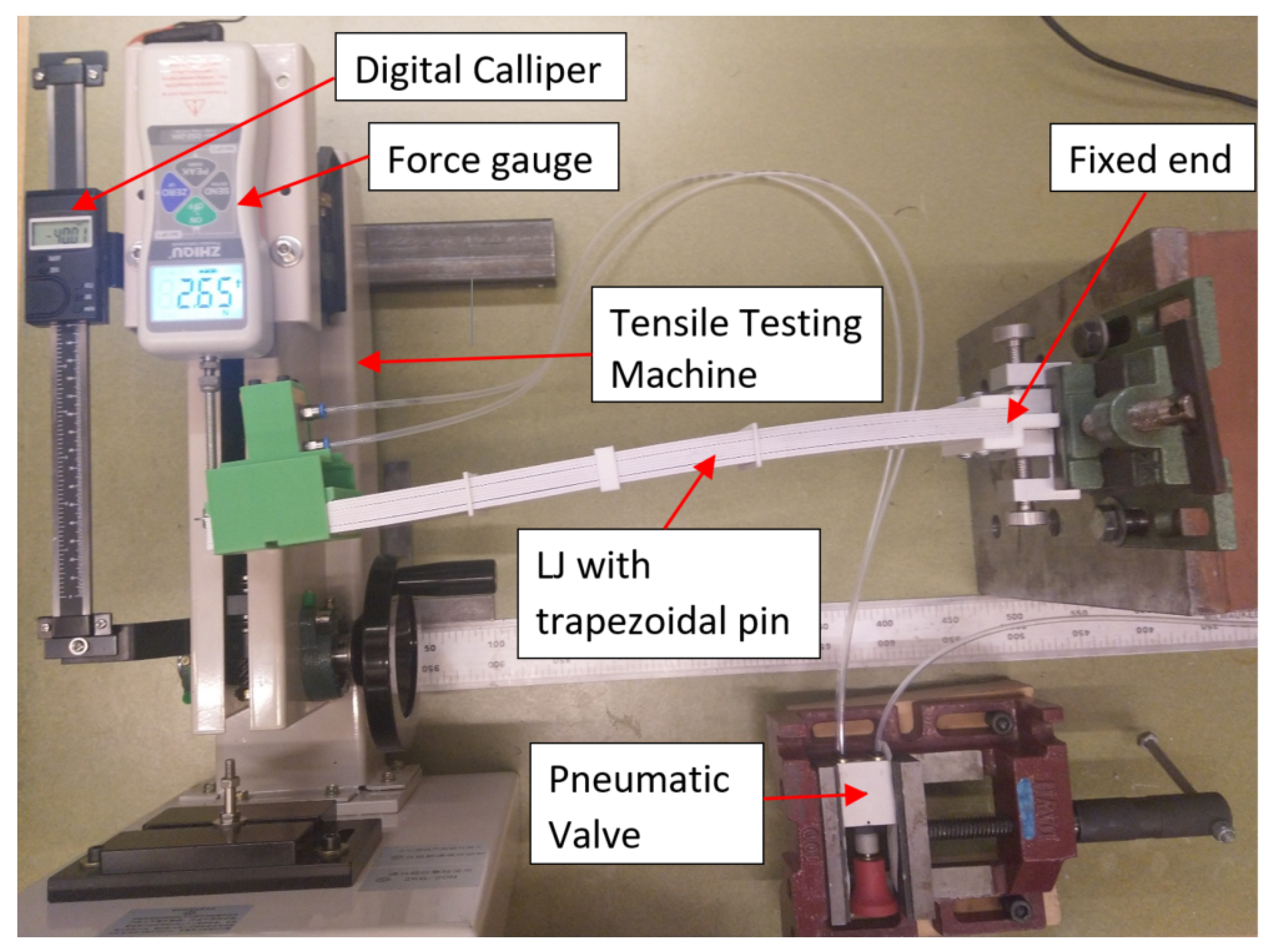
The FE models were developed in Ansys with the same components and dimensions as the experimental set up presented in
Section 2 and
Section 3. The FE model has the same geometry, materials, boundary conditions, and load conditions that were implemented in the experiment. This means that the LJ model is fixed in one of its ends, deflection was applied at the free end following the same values that were imposed in the test, the pressure in the pneumatic cylinder is implemented as a pair of forces that are applied to the cylinder body and the cylinder rod, and the value of these forces correspond to the forces applied by the cylinder when it is pressurized at the same values of pressure of the experiment. The result of the simulations was the force associated with each value of the applied deflection.
The coefficient of friction (COF) between the sheets was measured by using an inclined-plane friction device [
38]. The same experiment was conducted between the layers and trapezoidal pin, and between the sheets and flat clamp. The results of these tests indicate that the COF between the sheets is 0.253, and the COF between the layers and flat clamp, and the COF between the layers and trapezoidal pin is 0.126. These COF values were used in the FE simulations.
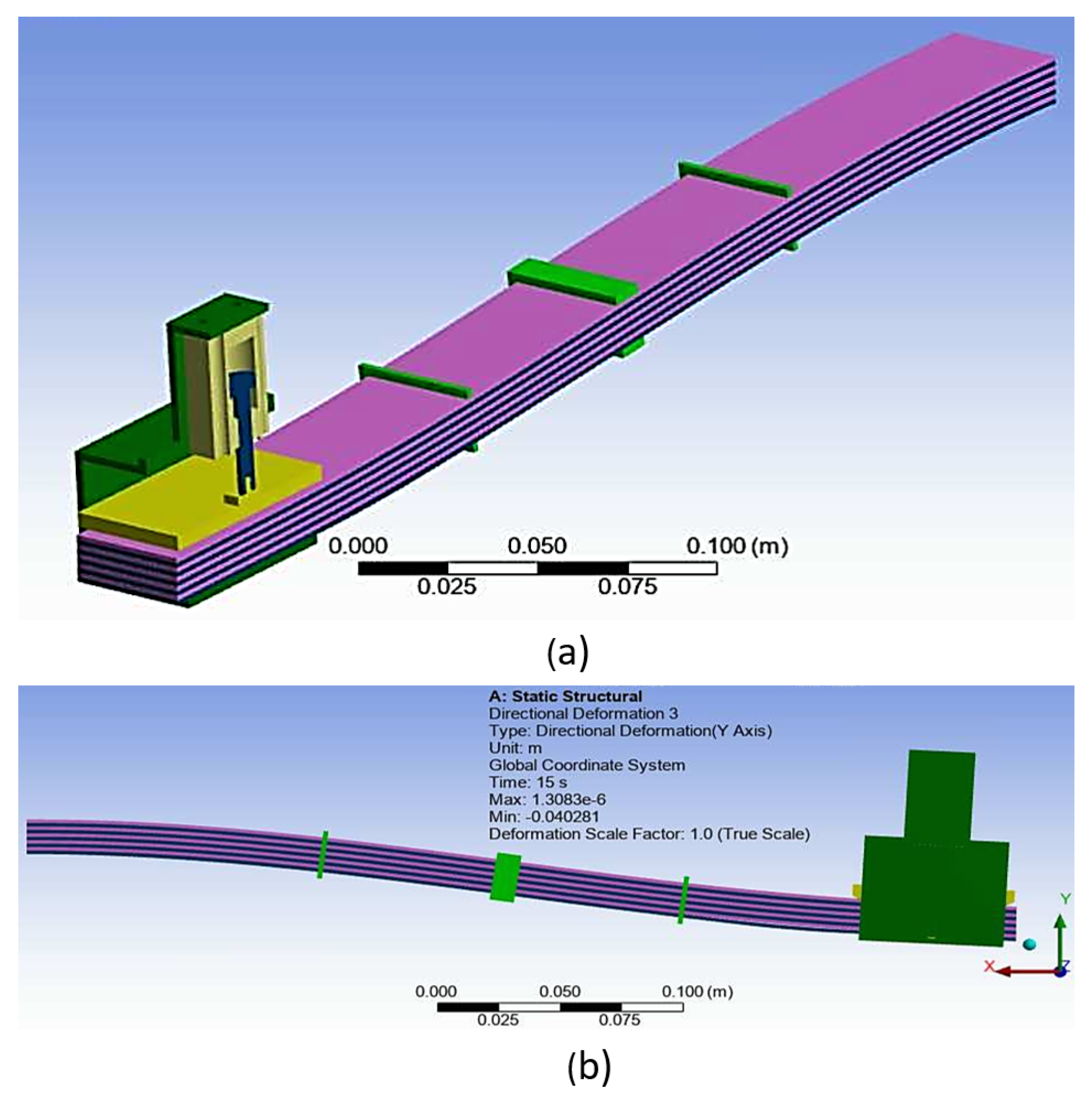
The most relevant details about the pre-process of the simulation are as follows. Only one half of the LJ structure is modeled and symmetry along the longitudinal plane was imposed as can be observed in
Figure 13a. The mesh of the sheets is composed of elements of quadratic order and all the layers have one element across the thickness. The Static Structural Solver was selected to carry out the simulation because the experiment was conducted in quasi-static conditions.
Large deflection is turned on considering that the maximum deflection in the experiment was about 10 % of the length of the LJ structure. The setup of the contact among the sheets, and between the sheets and the pin had a critical role in the convergence of the solution. In this aspect, the most relevant parameters are the Contact Formulation, which was selected as Augmented Lagrange, the stiffness, which is updated in each iteration, and the normal stiffness factor, which is set up as 0.01. The maximum number of equilibrium iterations per solution step is 50 and was defined through the command NEQIT.
Figure 13b shows the shape of the LJ with trapezoidal pin at a locking pressure of 800 kPa when it reaches 40 mm of deflection, which is the maximum deflection of the free end that was applied in the experiment and replicated in the simulation. It can be seen that the curvature of the LJ structure is very low in the segment that is near to the trapezoidal pin mechanism. Basically, the action of the trapezoidal pin makes that segment of the LJ structure straight.
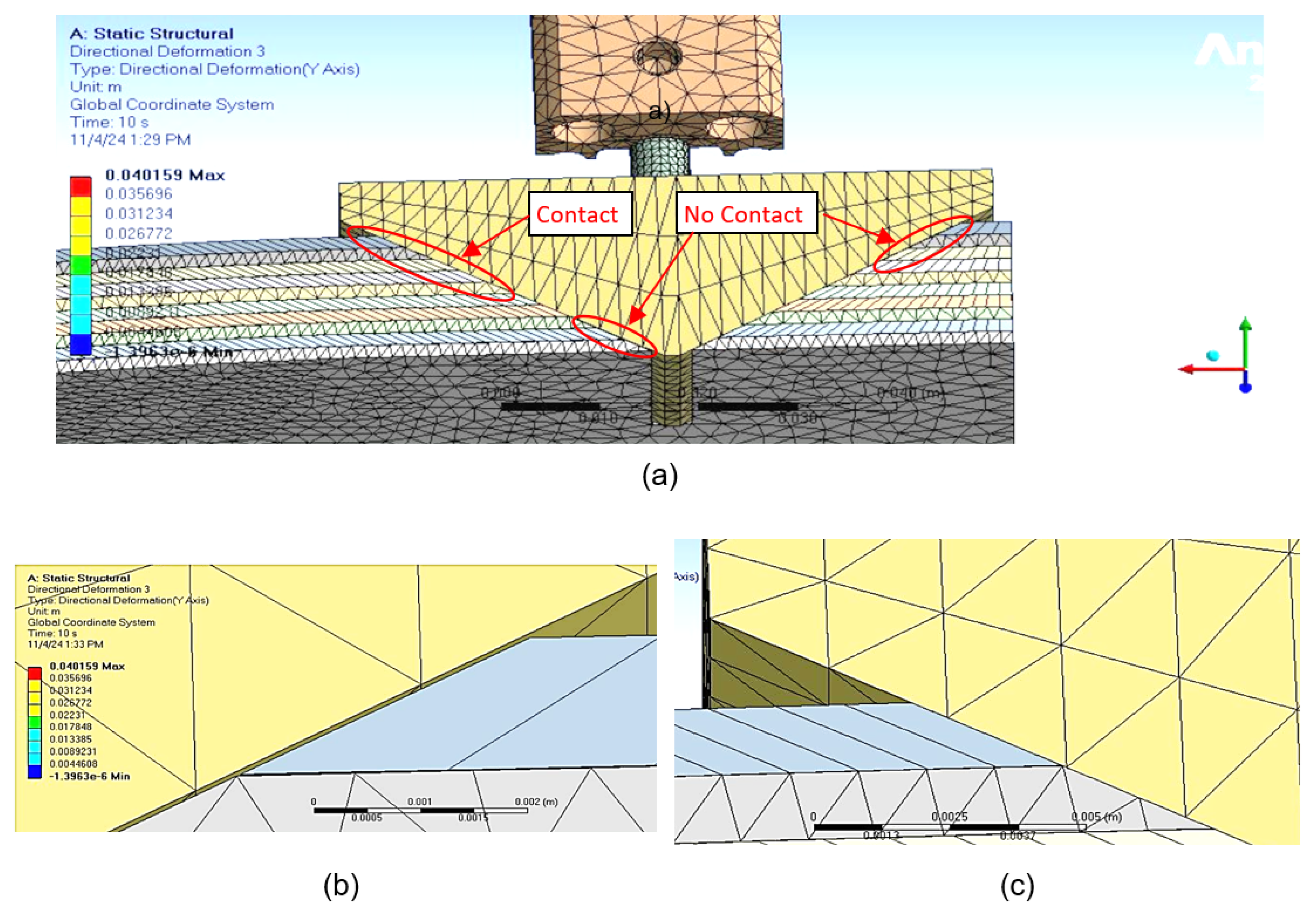
Figure 14 illustrates some details that were not possible to observe in the bending test.
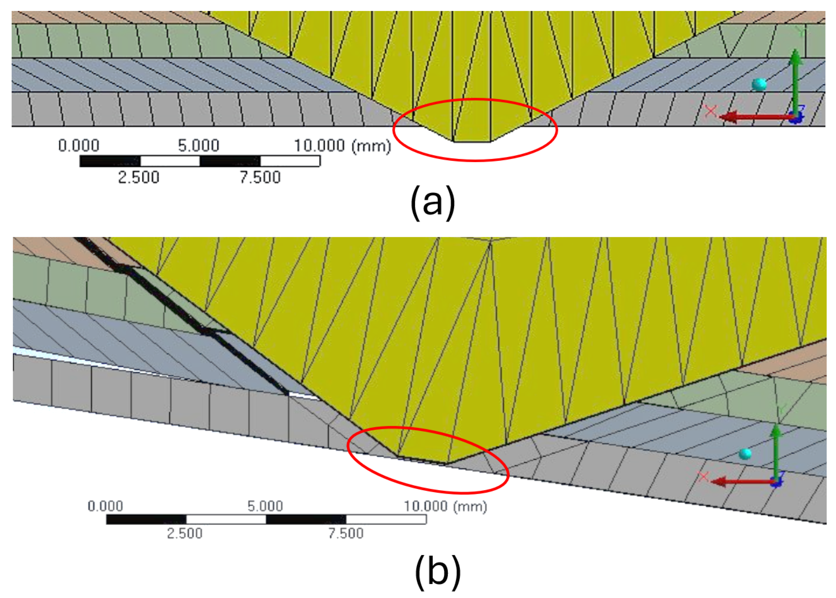
Figure 14a,c show that the trapezoidal pin only keeps contact with some of the top sheets in the front of the pin.
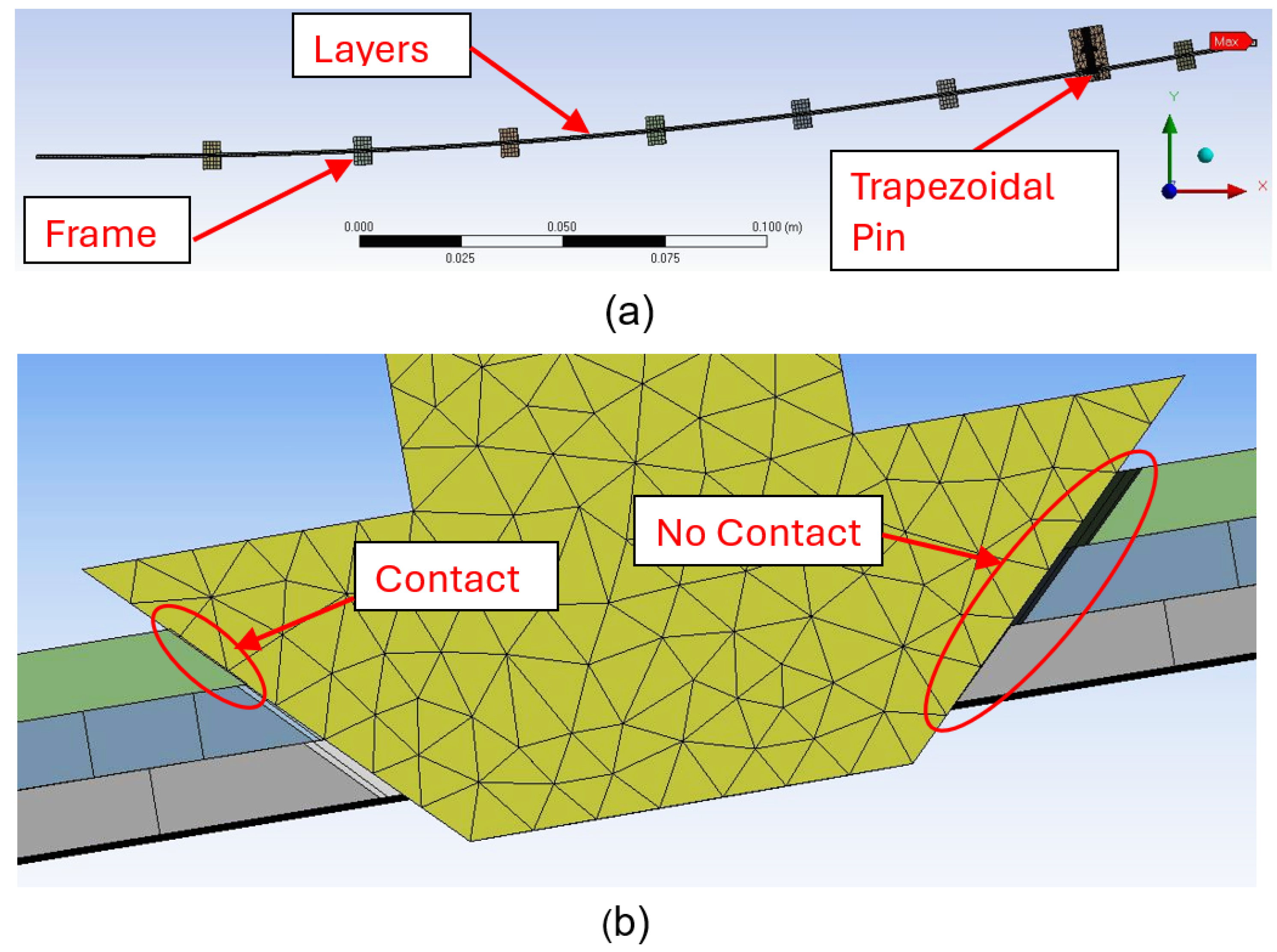
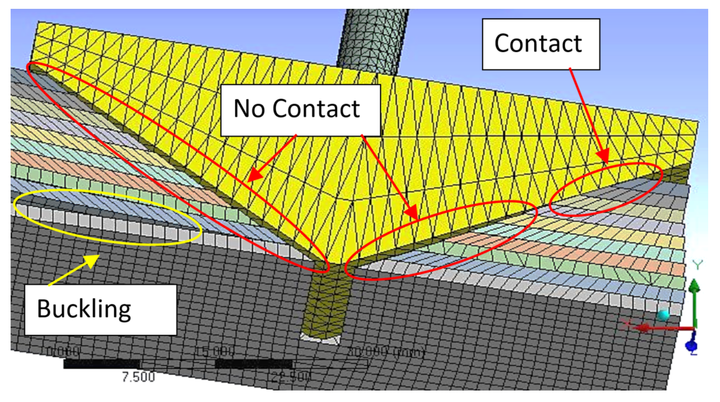
Figure 14b illustrates how the contact between the layers and the trapezoidal pin is missing in the back part of the pin. This figure also shows the relative slip between the sheets. The areas of contact and no-contact are more evident in Figure 31. The consequences of the existence of these areas are also explained in the
Section 5.4.
The cause for the existence of the contact and no-contact zones is the fact that slip between the layers depends on the distance from the clamp end to the position of analysis along the LJ structure. When the laminar jamming is bent, the slip between the layers in the clamp end is zero, then the slip differs from zero as the point of analysis moves along the beam [
22]. In addition, the slip between the layers also depends on the position of the layers in relation to the bottom layer. It is necessary to remember that trapezoidal pin is ultimately attached to the bottom layer. In other words, the trapezoidal pin can move perpendicularly to the bottom layer, but both components remain in the same position along the beam. Therefore, when the LJ structure is bent, all the layers move or try to move in relation to trapezoidal pin, except for the bottom layer.
Another aspect that was investigated through the FE simulations is the possibility of plastic deformation of the ABS sheets during the bending experiments.
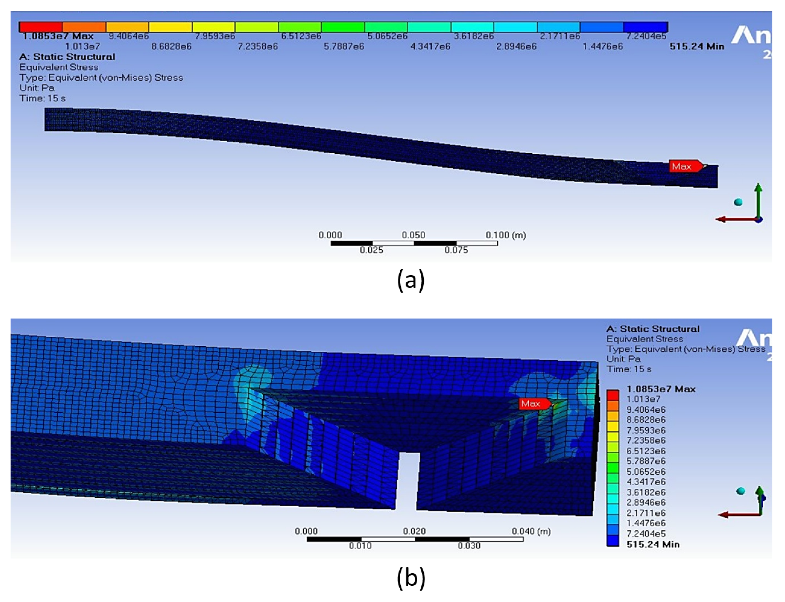
Figure 15 illustrates the Von-Mises stresses of the ABS laminates when air pressure in the cylinders is 800 kPa and the deflection in the free end of the LJ structure is 40 mm (the same simulation as
Figure 13), which was the maximum deflection in the experiment. It can be seen that the maximum stress in the sheets is 10.8 MPa and occurs in the trapezoidal slots in the top layers. The maximum stress at this point is probably caused by the contact between the trapezoidal pin and the top layers. Another cause of the maximum stress in this location is the proximity to the edge where the trapezoidal slot starts, which generates a stress concentration factor. This stress value is less than the yield strength of ABS (39 MPa according with the sheets manufacturer). Therefore, plastic deformation does not occur in the ABS sheets. This result matches the experiment where no damage or plastic deformation in the ABS sheets was observed after the bending tests.
Experiments Versus Simulations
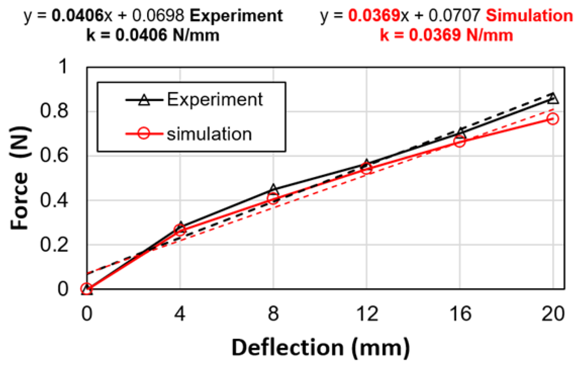
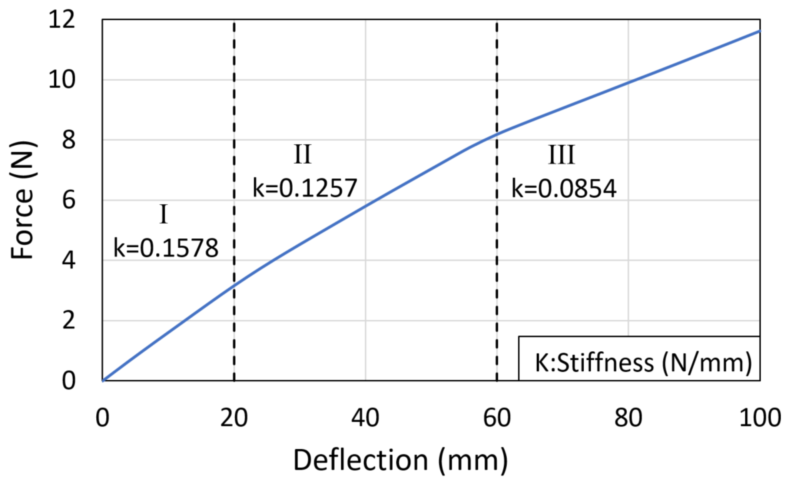
Figure 10 shows the results of the experiment compared with results from the FE simulations for the LJ structure with trapezoidal pin at 50 kPa. It can be seen that the simulation results agree well with the experimental results. The results are compared from 0 mm to 20 mm in the loading part of the cycle, as the same range was considered in the studies about DLJ [
14,
15]. The results were a stiffness of k = 0.0369 N/mm in the simulation, and a stiffness of k = 0.0406 N/mm in the experiment. Thus, the simulation error with respect to the test is about 9.1% in this case.
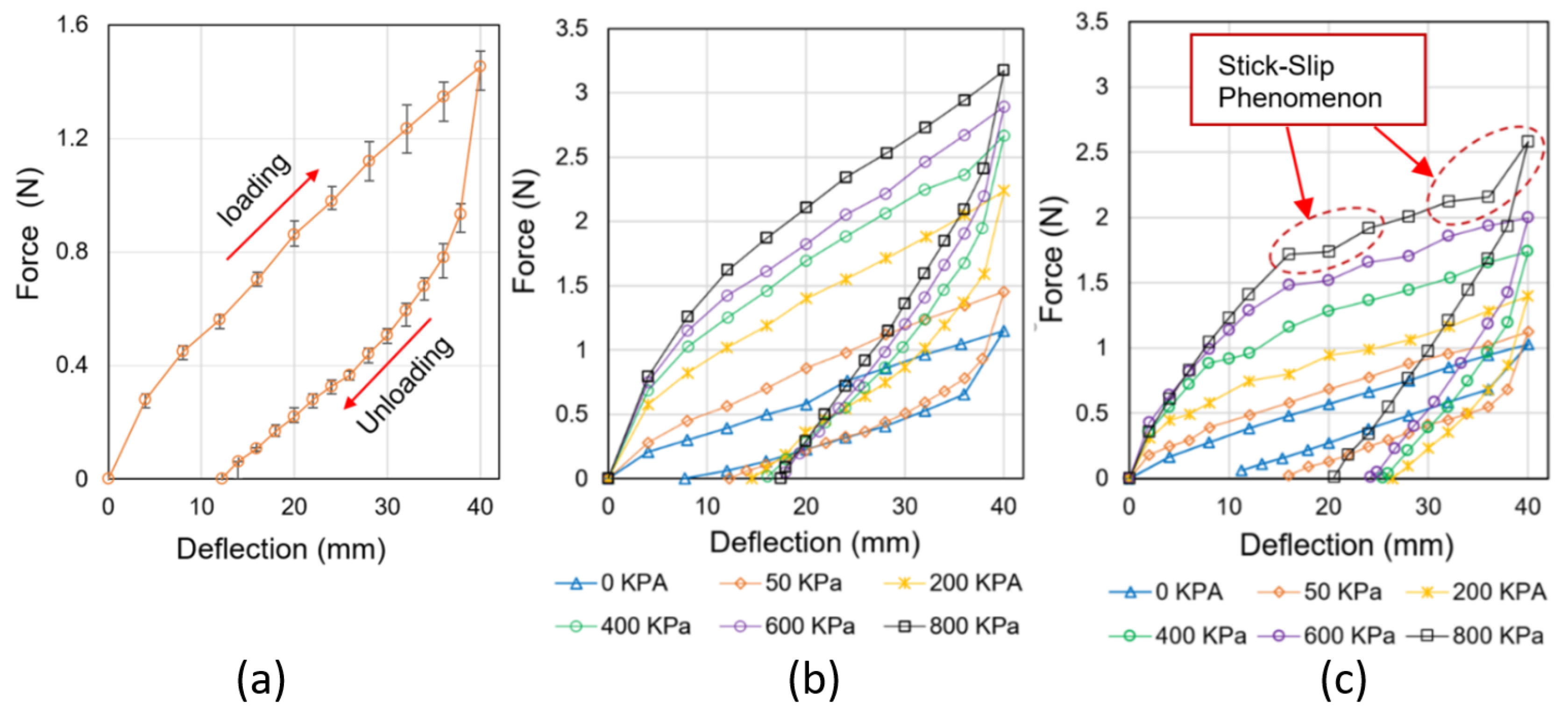
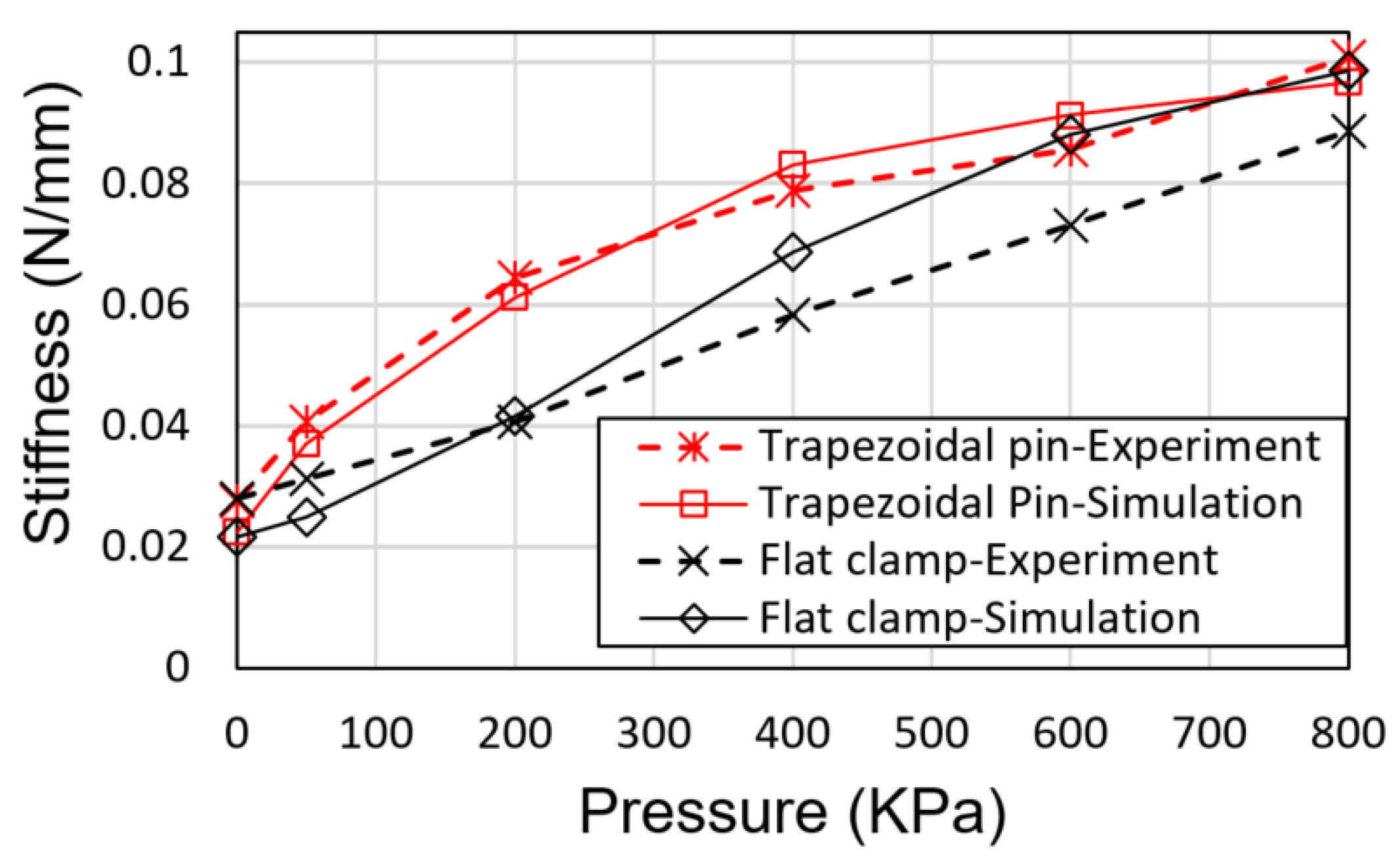
Figure 11 shows a comparison of the simulation and the experimental stiffness values for all pressure states that were tested in the experiments. For the case of the LJ structure with trapezoidal pin, it can be seen that the results of the simulations match well the results of the experiment. The maximum difference is about 10% and occurs at 0 kPa. This difference occurs because the ABS layers are not totally flat, which results in gaps between the sheets when there is not any locking force that keeps them together. On the other hand, the ABS layers in the simulations are modeled as totally flat and they remain together even when there is not any locking force on them. For the case of the LJ structure with flat clamp, it can be seen that the results of the simulation follow the same trend of the experiment but with a maximum error about 20%. The FE simulations do not present the stick-slip phenomenon that occurs in the tests of the LJ structure with flat clamp, which may be the cause of the difference between the experimental and the simulation results in this case.
6. Conclusions and Future Work
In this article, we presented a novel mechanism to lock/unlock the sheets of a LJ structure with the purpose of modifying its stiffness and making it useful for the construction of VSL robots. The mechanism consists of a pneumatic actuator that drives a trapezoidal pin to interfere mechanically with the layers and, in turn, modulating the stiffness of the LJ structure. Another LJ with a flat clamp mechanism is presented for the purpose of comparing the mechanical behavior of both mechanisms.
The trapezoidal pin mechanism has some significant advantages over the vacuum pressure mechanism, as the proposed mechanism does not require an airtight chamber. Therefore, it is not vulnerable to sealing damage due to contact with rough edges. In addition, the proposed mechanism can reach higher values of stiffness since it applies a positive pressure that could reach up to 7.9 atm (800 kPa), which is the standard pressure of industrial pneumatic installations, while the vacuum pressure mechanism is limited to a maximum pressure of 1 atm (101.3 kPa). Another advantage of the trapezoidal mechanism is that the transition from rigid state to flexible state or vise-versa does not require additional manipulations while the vacuum pressure mechanism may require to be disconnected from the vacuum regulator and flexed multiple times to return to ambient pressure. Furthermore, the trapezoidal pin mechanism has the potential to change the stiffness faster than the vacuum pressure mechanism, making the proposed mechanism adequate for mitigating impacts between robot arms and human beings.
Force-deflection tests were conducted to characterize variations of bending stiffness in the LJ structures due to changes in air pressure in the pneumatic cylinder. The results demonstrated that the maximum stiffness ratio of the trapezoidal pin is about 15% larger than the maximum stiffness ratio of the flat clamp. In addition, the experiments showed that the stick-slip phenomenon occurs in the flat clamp mechanism, but it is not present in the trapezoidal pin mechanism.
Both lock/unlock mechanisms were simulated by finite element (FE) methods. The results of the FE simulations match well the test results in the case of the trapezoidal pin mechanism. In the case of the flat clamp mechanism, the FE simulations differ considerably from the experiments. This difference may happen because the FE simulations do not replicate the stick-slip phenomenon that happens in the tests of the LJ structure with flat clamp.
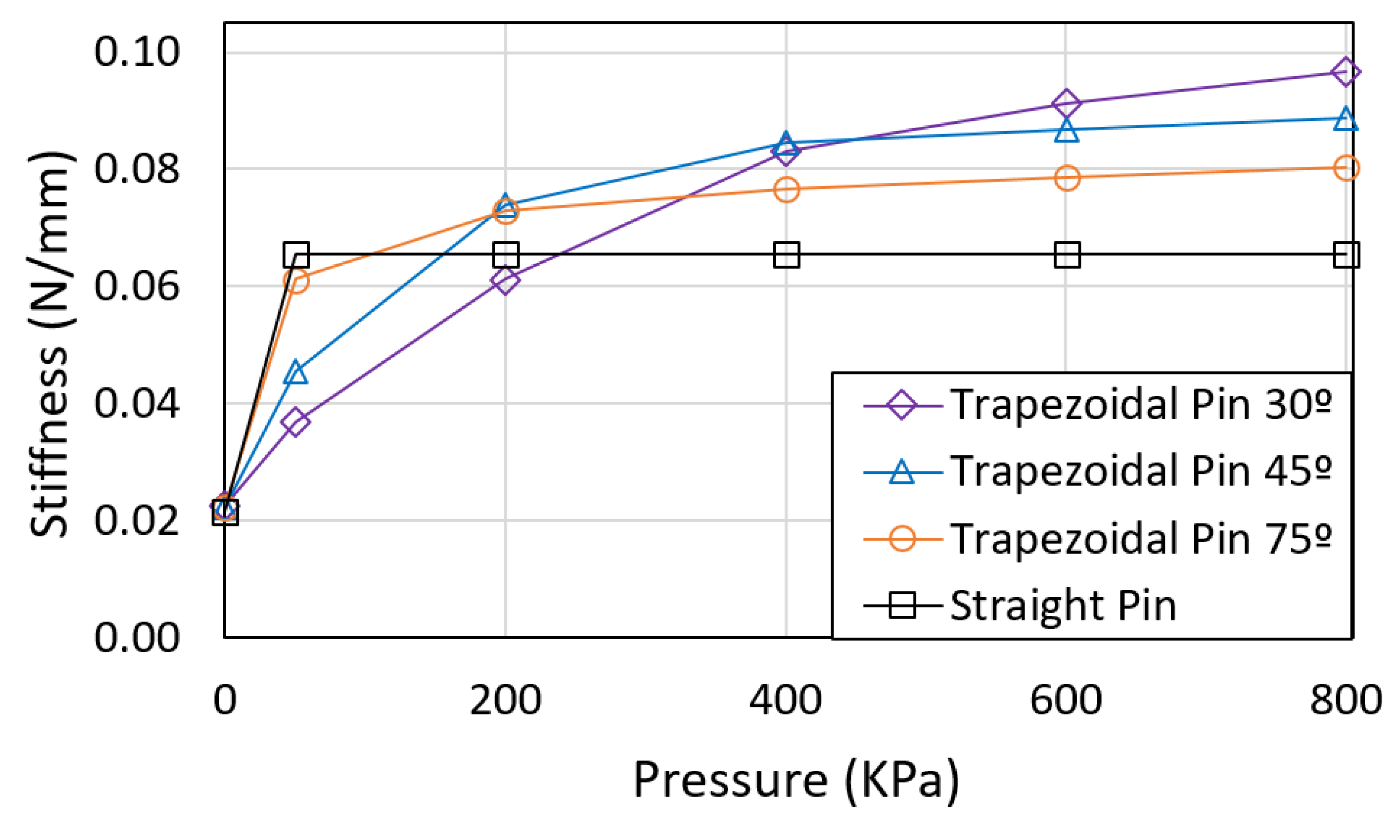
Computational case studies were carried out using FE simulations to study the effect of the angle of the trapezoidal pin in the LJ. The simulations show that the 30° trapezoidal pin has the highest stiffness for pressures greater than 500 kPa, while the 75° and 90° trapezoidal pins have the highest stiffness for pressures lower than 200 kPa.
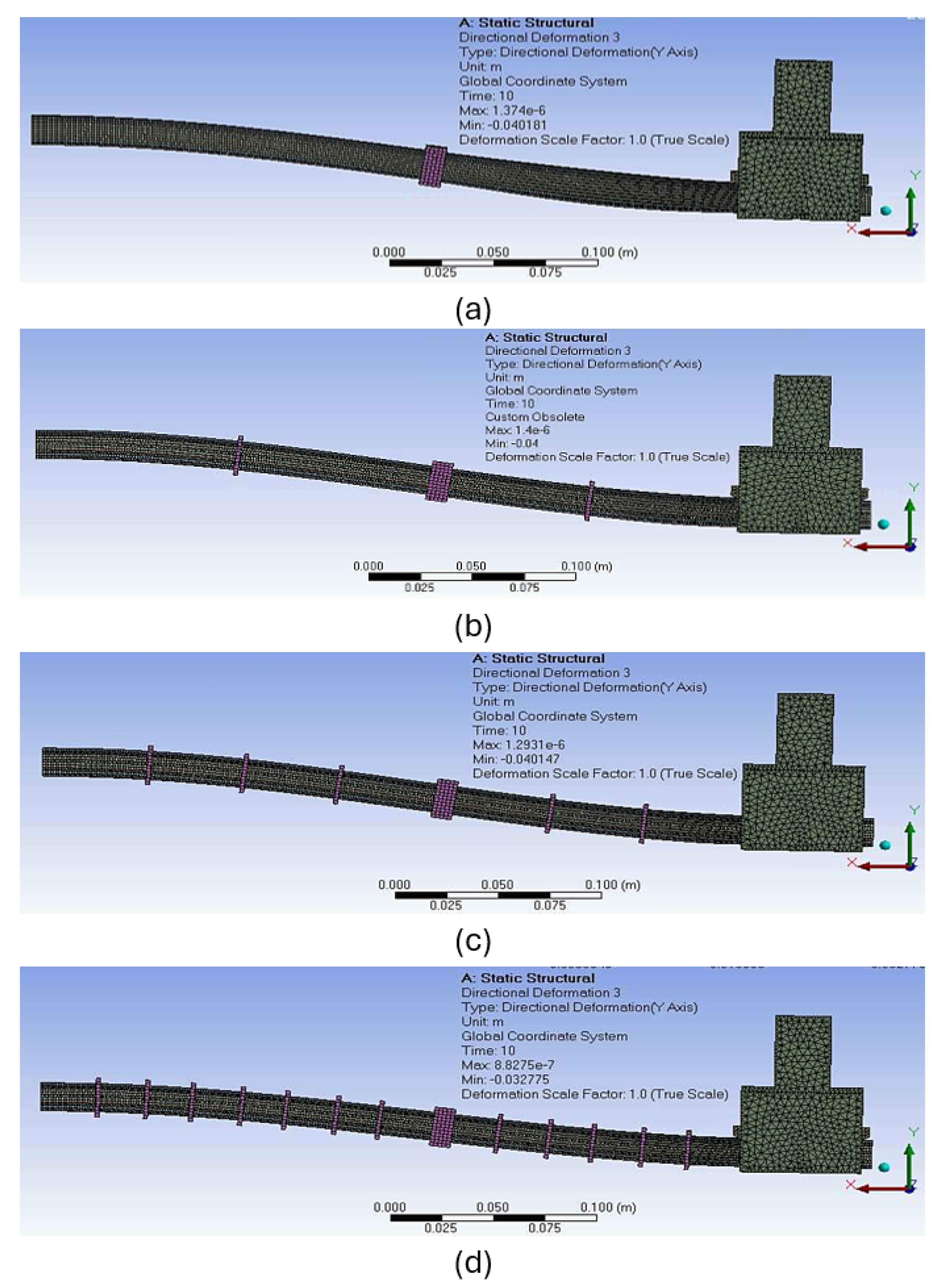
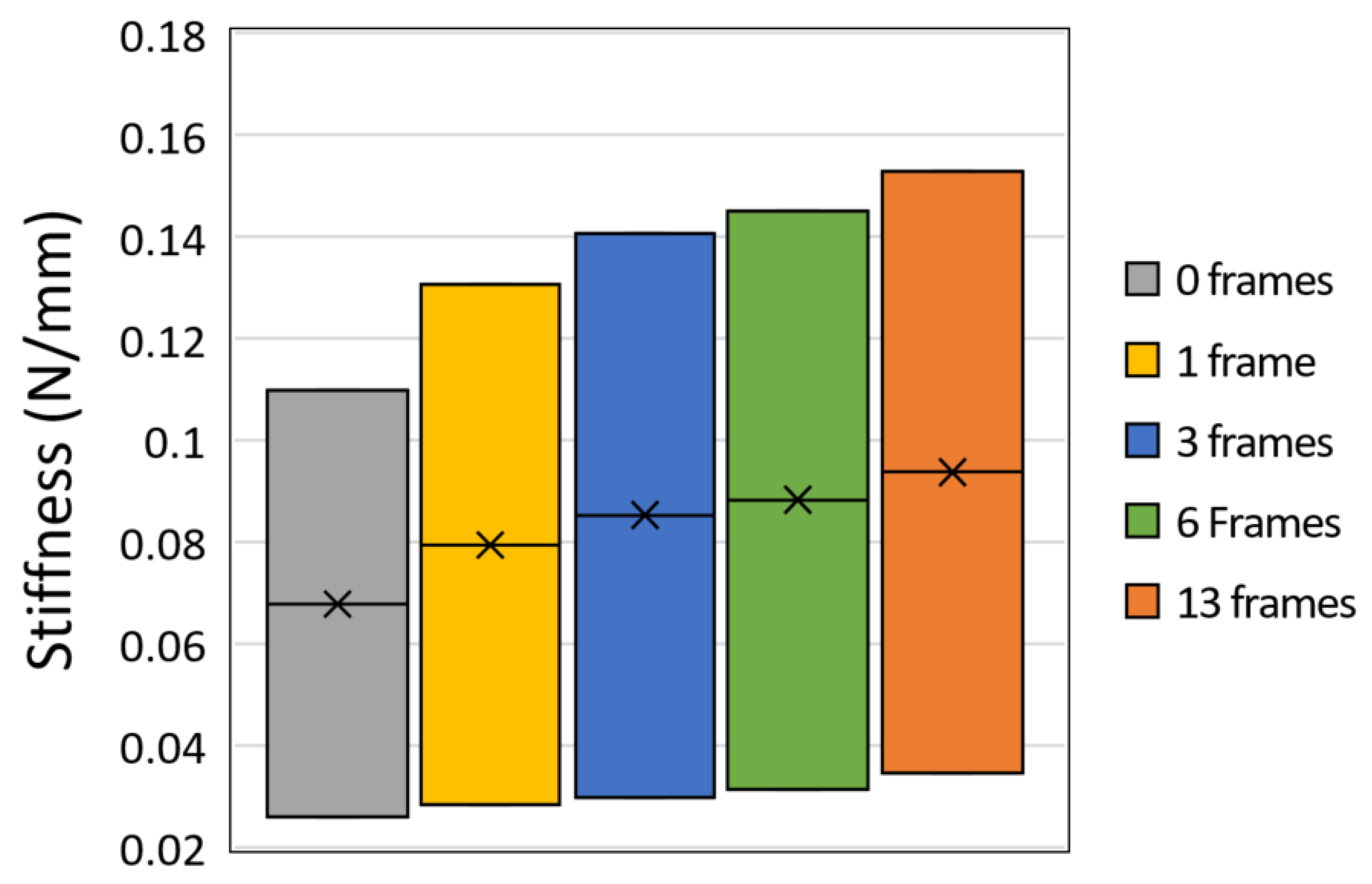
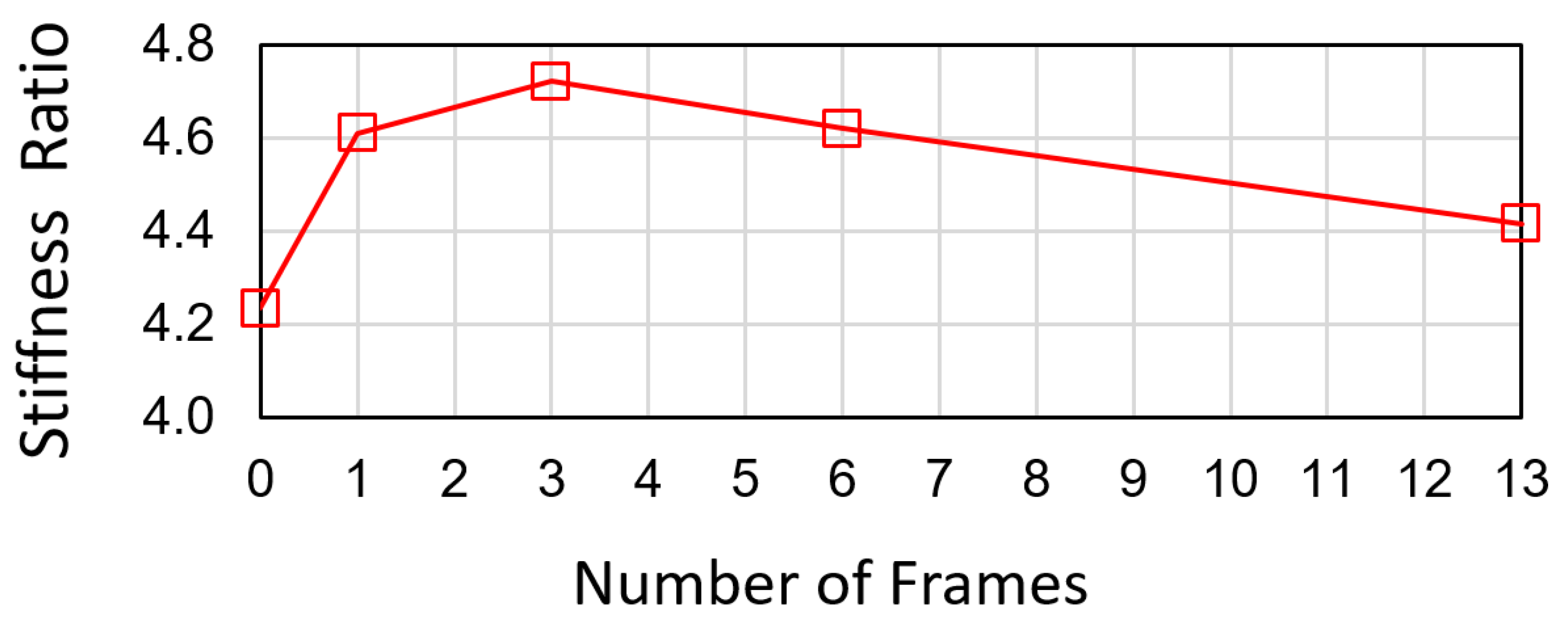
Another computational study was carried out to investigate the effect of the number of frames placed along the LJ with trapezoidal pin. FE simulations show that the increment of the number of frames results in an increased average of the stiffness range. Furthermore, the stiffness ratio reaches a maximum value when there are three frames in the LJ structure, showing an increase of about 11.5% in relation to the minimum stiffness ratio. Overall, altering the number of frames is a practical and novel method of modulating the stiffness range without including more actuators in the LJ structure.
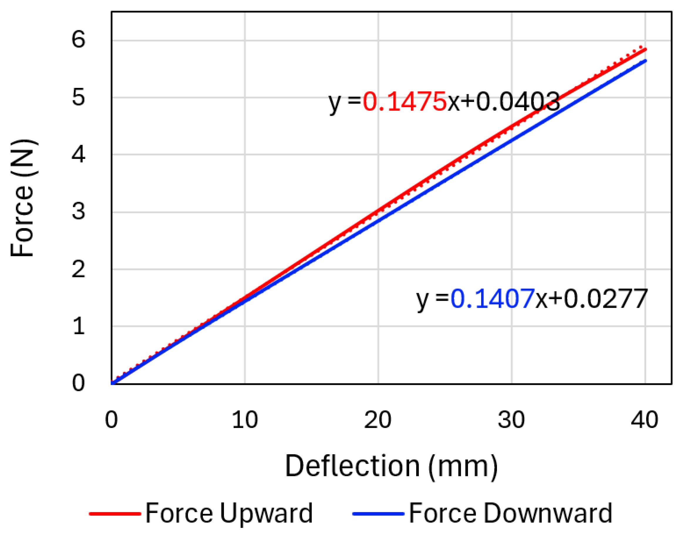
The behavior of the LJ structure with a trapezoidal pin when it is bent upward was also studied through FE simulations. The simulations demonstrate that the contact areas between the trapezoidal pin and the layers flip sides in comparison to the LJ structure when it is bent downward. The results of the simulation also show that the stiffness of the LJ structure when it is bent upward is slightly higher than the stiffness of the LJS when it is bent downward. This difference in the results occurs because of the variation in the location of the contact zones between the pin and the sheets of the LJS.
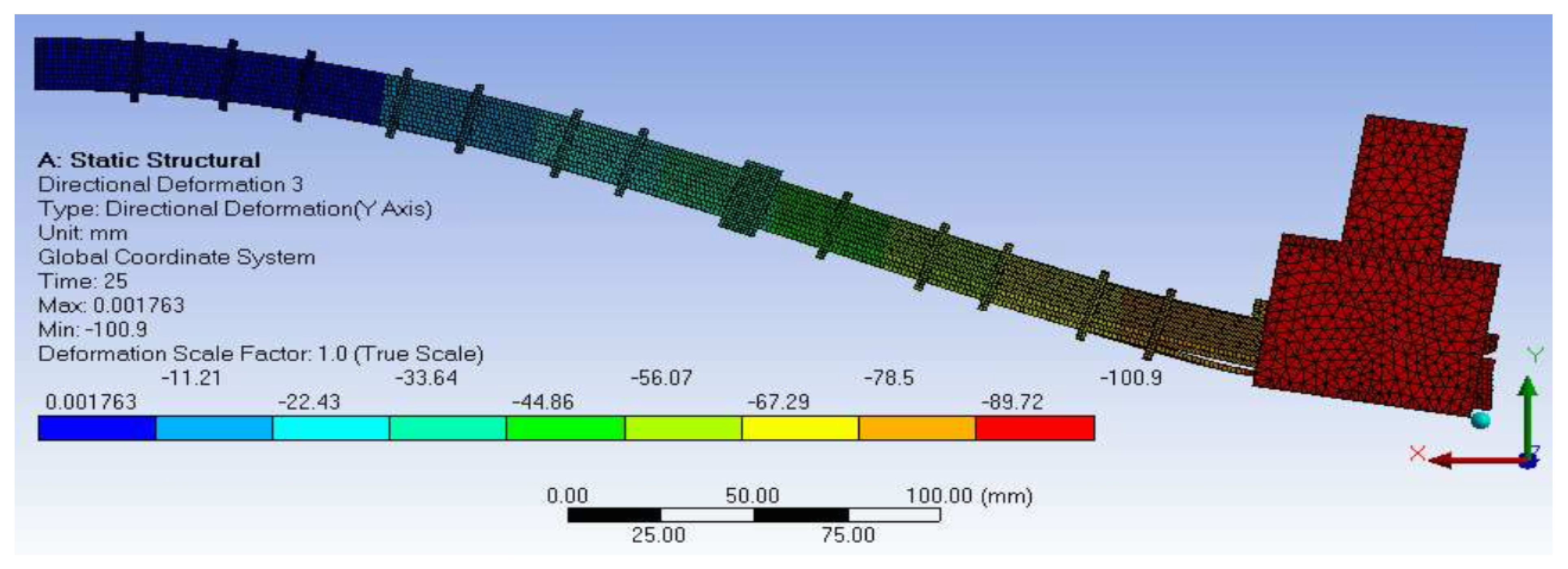
The behavior of the proposed mechanism when deflections are large was also analyzed through FE analysis. The simulations demonstrate that the stiffness of the LJ structure diminishes when the deflection increases beyond 10% of the length of the LJ structure. In addition, it is evident that at large deflections, the layers of the LJ structure push the pin upwards and the pin keeps contact only in the first top layers.
Future work should focus on the formulation of new designs of VSLs that are based on LJ structures activated by trapezoidal pin mechanisms and the investigation of impact between those VSLs and human beings to evaluate the potential reduction in injury severity in human operators. The design of VSLs that incorporate LJ structures has some challenges that have not been addressed in the literature such as ensuring that the VSL properly supports all load conditions (axial force, bending, and torsion) and reducing the volume of the VSL. Furthermore, the proposed mechanism should be evaluated in terms of performance to carry out the tasks of typical cobots in order to determine how possible it is to apply it in such applications.
Reducing the volume of the actuators and increasing the lock/unlock force is desirable if this type of mechanism is implemented in VSL robots. The combination of trapezoidal pin and pneumatic actuator could be improved in order to achieve this objective. Pneumatic cylinders are easy to couple with the trapezoidal pin but they become bulky if more force is required. Other types of pneumatic actuators, such as air bellow actuators, can provide larger forces while they are smaller than pneumatic cylinders. In addition, other types of actuators could be explored to drive the trapezoidal. For instance, piezoelectric actuators could be used to drive the trapezoidal pin and achieve high speeds of stiffening and destiffening. In the case of DLJ, piezoelectric actuators are also being considered to drive the flat clamp mechanism [
15]. Part of the future work proposed in this section has been carried out and presented in a subsequent study [
35].
