Article

Vibration Reduction and Stability Investigation of Van Der Pol–Mathieu–Duffing Oscillator via the Nonlinear Saturation Controller

1
Department of Basic Science, Modern Academy for Engineering and Technology, Elmokattam, Cairo 11439, Egypt
2
Physics Department, College of Science, Imam Mohammad Ibn Saud Islamic University (IMSIU), Riyadh 11623, Saudi Arabia
3
Department of Mathematics, Faculty of Science, Zagazig University, Zagazig 44759, Egypt
4
Department of Physics and Engineering Mathematics, Faculty of Engineering, Tanta University, Tanta 31734, Egypt
*
Author to whom correspondence should be addressed.
Actuators 2025, 14(9), 427; https://doi.org/10.3390/act14090427
Submission received: 3 August 2025 / Revised: 25 August 2025 / Accepted: 29 August 2025 / Published: 31 August 2025

Abstract

This study investigates the effect of a nonlinear saturation controller (NSC) on the van der Pol–Mathieu–Duffing oscillator (VMDO). The oscillator is a single degree of freedom (DOF) system. It is driven by an external force. It is described by a nonlinear differential equation (DE). The multiple-scale perturbation method (MSPT) is applied. It gives second-order analytical solutions. The first indirect Lyapunov method is used. It provides the frequency–response equation. It also shows the stability conditions. Internal resonance is included. The analysis considers steady-state responses. It studies simultaneous primary resonance with a 1:2 internal resonance ( Λ 1 ϖ 1 and ϖ 1 2 ϖ 2 ). Time–response simulations are presented. They show controlled and uncontrolled systems. Numerical solutions (NSs) are obtained with the fourth-order Runge–Kutta method (RK-4). They are compared with the approximate analytical solution (AS). The agreement is strong. It confirms the perturbation method. It shows that the method captures the main system dynamics.

1. Introduction

In the 1920s, Dutch researcher Balthasar van der Pol, who was researching electrical circuits, invented the famous nonlinear system known as the van der Pol oscillator. The VMDO is a fundamental model in nonlinear dynamics, renowned for its ability to capture complex oscillatory behaviors across diverse fields. It uniquely combines nonlinear damping and nonlinear stiffness. This synergy allows it to accurately model phenomena such as heartbeats, bridge vibrations, and electrical circuit instabilities. Recently, vibration control in mechanical structures has become a major research topic, as it is essential for structural safety and efficiency. Therefore, this research aims to develop and analyze a nonlinear control strategy for suppressing VMDO vibrations. Xu et al. employed time-delayed linear and nonlinear time-delayed position feedback control motions of a van der Pol in [1]. Vibration is controlled by employing a positive position feedback (PPF) controller, and an approximate solution is provided through the MSPT approach [2]. Two types of van der Pol oscillators with fractional-order terms were introduced in [3], where the averaging method was applied to obtain approximate solutions. In these cases, the damping coefficient was increased to nearly its maximum value, while the additional stiffness coefficient was reduced to almost zero. The effects of two periodic excitations with widely different frequencies on the nonlinear response of a bistable VMDO were analyzed in [4]. It was shown that, by adjusting the high-frequency drives and parametric oscillation intensities, a symmetric bistable potential could be transformed into a symmetric monostable potential. Proportional–derivative control and negative velocity feedback (NVC) were applied in [5,6,7,8] to regulate different systems. The dynamic features of a VMDO under two periodic excitations and a distributed time delay were investigated in [9]. A pitchfork bifurcation was observed, induced by high-frequency internal excitation and low-frequency external stimulation, and the fractal behavior of the system was analyzed when the two excitation frequencies coincided. The suppression of hysteresis in a forced nonlinear self-sustained oscillator operating near primary resonance was explored in [10]. To investigate the inhibition effect, rapid forcing was applied to the oscillator. A perturbation-based analytical method was employed to identify the influence zone, the quasi-periodic control domain, and the hysteresis region. Time-delay techniques have been employed in several studies to suppress vibrations in nonlinear systems, owing to the active and delayed spring characteristics of the control mechanism [11,12,13,14]. The van der Pol equation was examined in [15] with a significant delay introduced into the cubic nonlinearity, where the delay factor was sufficiently large. The dynamics of the van der Pol equation under such delays were found to be complex and highly variable.
The impact of coupling coefficient changes and insertion loss on the extraordinary point displacement in a two-coupled degree of freedom system was examined in the work in [16]. According to the investigation, adjusting the nonlinearity coefficient decreased the resonance frequency shift at the exceptional point as well as the oscillation amplitude. The authors of [17] utilized a cubic negative velocity controller (CNVC) to control vibrations and estimate the solution through an averaging perturbation approach, with an emphasis on a mass-damper-spring model. To investigate nonlinear mode coupling between micro- and nano-beam resonators, well-regulated and reproducible experiments were provided in [18]. Other micro- and nanostructures could benefit from this experimental method to better understand their nonlinear interactions and take advantage of them for more sensitive and quieter responses. Three types of nonlinear interactions between the first and third bending modes of vibrations of slightly curved beams (arches) using electrothermal tuning and electrostatic excitation were illustrated: two–one internal resonance, three–one internal resonance, and mode veering (near crossing). The experimental process was carried out in air and at ambient temperature, is very flexible and reproducible, and does not require precise or sophisticated manufacturing.
Ref. [19] utilized NSC with a van der Pol oscillator. They also used perturbation and direct numerical integration solutions to investigate the impact of feedback gains, the primary goal of Warminski et al. A flexible beam with MFC actuators was to be used with specially designed controllers [20]. Using the perturbation technique, mathematical solutions for the beam using NSC were found. In terms of minimizing system vibration, PPF and NSC controllers are the most effective. An approximation for nonlinear oscillators was obtained by Nayfeh et al. [21] and Mickens [22]. Motamid [23] combined the homotopy perturbation method with the Laplace transformation for parametric DEs, and an approximated bounded solution was generated. In contrast to automated frequency dampers, the van der Pol oscillator is a well-known nonlinear oscillator that has been extensively studied and has implications that are still being addressed today. MSPT is used to create the mean equations that compute the amplitudes and phases for the first-order approximation solutions. The nonlinear damper can effectively reduce the amplitude of the principal resonance response. In order to solve the Cauchy problem of the van der Pol equation in the complex domain, [24] employed the analytical approximate technique. For both simple and complex scenarios, analytical continuation is possible with these approximations. To manage the computational process and increase the precision of the end results, they examined the impact of variance in the problem’s original data.
Orlov and Chichurin [25] investigated the unstable and dynamically stable behavior of the system. Furthermore, he provided statistical evidence that the oscillator’s amplitude rises when the stability requirements are not fulfilled. It is numerically shown that the nonlinear receiver is effective in lowering the nonlinear vibrations of the primary nonlinear oscillator under primary resonance conditions. A thorough parametric analysis was conducted in [26] to assess how important design elements affected the overall stability of the system. Complex nonlinear dynamics, including disconnected resonance curves and periodic stability to chaotic behavior transitions, were discovered. Additionally, several control strategies have been studied and proven to reduce the dangerous vibrations produced in various nonlinear systems [27,28,29,30]. The fourth-order Runge–Kutta approach yielded numerical findings that further validated the precision of these responses. Resonance examples were used to determine the characteristic exponents and solvability requirements. Additionally, they were employed to show the frequency–response curves. By looking at the stability and instability ranges, the nonlinear stability analysis was carried out. Authors of [31,32,33,34] demonstrated a novel method for solving differential delay equations using the MSPT approach that allows for precise approximation of solutions over extended periods of time.
Alluhydan et al. [35] indicated the effect of CNVC on the vibration of a quarter-car model and compared proportional derivative (PD), linear negative velocity control (LNVC), PPF, negative derivative feedback (NDF), and CNVC. Authors of [36] demonstrated the many zones of stability and instability of a dynamic system within frequency–response curves, as well as the act of changing parameters on the system’s behavior. Arena [37] used the asymptotic method of MSPT; an ordered hierarchy of linear perturbation equations governs the periodic cell’s nonlinear dynamics. In order to investigate the linear and nonlinear dispersion properties, the Floquet–Bloch theory is iteratively used at each order of the perturbation equations due to its linearity and spatial periodicity. Razzaq et al. [38] looked at primary issues with the employed method when it is applied to small-scale systems, like the incapacity to qualify acceleration and restoring forces, and they estimated the system’s restoring forces and nonlinearities using a combination of analytical methods, experimental data, and Lagrange polynomial interpolation. Erturk et al. [39] found the series solution of the coupled asymmetric van der Pol oscillator in two dimensions and presented the NS by the Runge–Kutta method. Abohamer et al. [40] examined the AS after adding NVC and negative cubic velocity feedback controllers to the van der Pol–Methieu–Duffing oscillator using the MSPT. Wei [41] used the two categories from the wake oscillator and one degree of freedom model, which depend on the van der Pol oscillator, and studied the stability of the system from an energy perspective. Taylor expansion was used to solve the DE. The results of nonlinear van der Pol oscillators were compared in three ways: ode15, ode45, and the fourth-order Runge–Kutta, as shown in [42]. A straightforward but efficient iteration process for finding the van der Pol equation’s solution is suggested in [43]. This process is a strong tool for figuring out a nonlinear equation of motion periodic solution. Furthermore, a comparison between the obtained solution and those obtained by the RK-4 was made, which demonstrated the precision of the iteration procedure applied.
Ref. [44] solved the nonlinear (VMDO) using a Morlet waveform neural network (MWNN) as a smart computing technique, simplified the intricate mathematical formulas employed in conventional numerical procedures to solve DE, and reduced the number of time-consuming stages.
The main advantage of employing NSC for the VMDO lies in its ability to effectively suppress nonlinear vibrations that arise from the combined effects of self-excitation and nonlinear stiffness. By introducing a saturation mechanism, the controller prevents excessive amplitude growth, reduces the risk of bifurcations and chaotic behavior, and enhances the overall stability of the system. Furthermore, NSC provides a practical means of vibration suppression without requiring excessive control effort, making it energy-efficient and suitable for real-world engineering applications. This approach not only improves structural reliability but also extends the operational lifetime of mechanical and aerospace systems subjected to complex dynamic excitations.
With the use of a suitable control technique, this study seeks to provide basic guidelines for removing high vibrations of the framework. In order to actively reduce excessive vibration for the nonlinear dynamical system, the NSC is taken into account. The perturbation technique produced an analytical conclusion that was almost simultaneous for both the primary and internal resonance cases. The perturbation approach utilizing the NSC process yields the FREs, stability analysis, and mathematical answers. Plotting and reporting of the effects of each parameter on the vibrating and NSC systems is performed, and the impacts of several parameters and the controller on the system are simulated employing MATLAB R2023b software.

2. Governing Equations and Approximate Solutions

The VMDO is a complex nonlinear dynamical system that combines features of the VMDO. This combination enables the modeling of a wide range of vibrational phenomena across various scientific and engineering disciplines. A van der Pol–Duffing oscillator’s equation of motion is represented by the following DE [45], which can be modified as follows:
χ ¨ + ε α 1 χ ˙ ε γ χ 2 χ ˙ + ϖ 1 2 χ + ε λ χ 3 + ε β χ 5 = ε f 1 cos ( Λ 1 t ) + ε χ f 2 cos ( Λ 2 t )
where χ denotes the displacement of the VMDO. χ ˙ and χ ¨ represent the velocity and acceleration, respectively. The parameter ϖ 1 is the system’s natural frequency, and ε is a small perturbation parameter. The coefficient α 1 corresponds to the linear damping. The parameters β , γ , and λ represent the nonlinearities terms. The excitation frequencies and amplitudes are Λ 1 , Λ 2 and f 1 , f 2 .
One possible way to express the DE of motion that describes the oscillations of the van der Pol with an NSC controller in this manner is as follows:
χ ¨ + ε α 1 χ ˙ ε γ χ 2 χ ˙ + ϖ 1 2 χ + ε λ χ 3 + ε β χ 5 = ε f 1 cos ( Λ 1 t ) + ε χ f 2 cos ( Λ 2 t ) + ε G 1 ϒ 2
ϒ ¨ + ε α 2 ϒ ˙ + ϖ 2 2 ϒ = ε G 2 χ ϒ
where ϒ represents the displacement of NSC. ϖ 2 is the NSC controller’s inherent frequency, and G 1 and G 2 are the control and feedback signals.
Figure 1 depicts the van der Pol–Duffing oscillator model with NSC in the following flowchart:

3. Perturbation Analysis

We used the MSPT [31,32,33] as follows to obtain the approximate answer up to the first approximation:
χ t ; ε = χ 0 T 0 , T 1 + ε χ 1 T 0 , T 1 + O ε 2 ϒ t ; ε = ϒ 0 ( T 0 , T 1 ) + ε ϒ 1 T 0 , T 1 + O ε 2
where T 0 = t and T 1 = ε t . The derivatives have the following forms:
d d t = D 0 + ε D 1 + d 2 d t 2 = D 0 2 + 2 ε D 0 D 1 +
Substituting from (4) and (5) in (2) and (3), then comparing coefficients that are roughly equivalent to the power of ε , we obtain:
O ε 0
D 0 2 + ϖ 1 2 χ 0 = 0
D 0 2 + ϖ 2 2 ϒ 0 = 0
O ε 1
D 0 2 + ϖ 1 2 χ 1 = 2 D 0 D 1 χ 0 α 1 D 0 χ 0 + γ χ 0 2 ( D 0 χ 0 ) λ χ 0 3 β χ 0 5 + f 1 cos ( Λ 1 T 0 ) + χ 0   f 2 cos ( Λ 2 T 0 ) + G 1 ϒ 0 2
D 0 2 + ϖ 2 2 ϒ 1 = 2 D 0 D 1 ϒ 0 α 2 D 0 ϒ 0 + G 2 χ 0 ϒ 0
Solving (6) and (7), we get the following:
χ 0 ( T 0 , T 1 ) = A ( T 1 )   e i ϖ 1 T 0 + A ¯ ( T 1 )   e i ϖ 1 T 0
ϒ 0 ( T 0 , T 1 ) = B ( T 1 )   e i ϖ 2 T 0 + B ¯ ( T 1 )   e i ϖ 2 T 0
where A and B are complex functions in T 1 . Substituting Equations (10) and (11) in Equations (8) and (9), we have
D 0 2 + ϖ 1 2 χ 1 = 2 i ϖ 1 ( D 1 A ) i α 1 ϖ 1 A + i γ ϖ 1 A 2 A ¯ 3 λ A 2 A ¯ 10 β A 3 A ¯ 2 e i ϖ 1 T 0                                                             β A 5 e 5 i ϖ 1 T 0 + G 1 B 2 e 2 i ϖ 2 T 0 + G 1 B B ¯ + i γ ϖ 1 A 3 λ A 3 5 β A 4 A ¯ e 3 i ϖ 1 T 0                                                             + f 1 2 e i Λ 1 T 0 + f 2 2 e i ( Λ 2 + ϖ 1 ) T 0 + f 2 2 e i ( Λ 2 ϖ 1 ) T 0 + C . C .
D 0 2 + ϖ 2 2 ϒ 1 = 2 i ϖ 2 ( D 1 B ) i α 2 ϖ 2 B e i ϖ 2 T 0 + G 2 A B e i ( ϖ 1 + ϖ 2 ) T 0 + G 2 A B ¯ e i ( ϖ 1 ϖ 2 ) T 0 + C . C .
C.C. is the complex conjugate. After neglecting the secular terms in Equations (12) and (13), the first AS can be written as
χ 1 = E 1 e 5 i ϖ 1 T 0 + E 2 e 3 i ϖ 1 T 0 + E 3 e i ϖ 1 T 0 + E 4 e i ( Λ 2 + ϖ 1 ) T 0 + E 5 e i ( Λ 2 ϖ 1 ) T 0 + E 6 e 2 i ϖ 2 T 0 + E 7 + C . C .
ϒ 1 = E 8 e i ( ϖ 1 + ϖ 2 ) T 0 + E 9 e i ( ϖ 1 ϖ 2 ) T 0 + C . C .
where E n ( n = 1 , 2 , , 9 ) are complex functions in T 1 and are given in Appendix A.
From the solutions found above. The following resonance instances were determined:
  (i)
Primary resonance: Λ 1 ϖ 1 or Λ 2 ϖ 1 .
 (ii)
Internal resonance: ϖ 1 2 ϖ 2 .
(iii)
Simultaneous resonance: Internal and primary resonance.
This research considers the simultaneous resonance situation ( Λ 1 ϖ 1 and ϖ 1 2 ϖ 2 ) to be the worst resonance case. In the next part, we will analyze and numerically examine the stability of this instance, respectively.

4. The Periodic Solution

The system stability is examined using the most damaging simultaneous resonance scenario ( Λ 1 ϖ 1 and ϖ 1 2 ϖ 2 ) from the first-order approximation. The detuning parameters σ 1 and σ 2 are obtained by
Λ 1 = ϖ 1 + ε σ 1 ,     ϖ 1 = 2 ϖ 2 + ε σ 2
Substituting Equation (16) into (12) and (13), we have
2 i ϖ 1 D 1 A = i α 1 ϖ 1 A + i γ ϖ 1 A 2 A ¯ 3 λ A 2 A ¯ 10 β A 3 A ¯ 2 + f 1 2 e i σ 1 T 1 + G 1 B 2 e i σ 2 T 1
2 i ϖ 2 D 1 B = i α 2 ϖ 2 B + G 2 A B ¯ e i σ 2 T 1
Exchanging all A ( T 1 ) and B ( T 1 ) by the polar form as
A ( T 1 ) = 1 2 a ( T 1 ) e i Θ 1 ( T 1 ) ,   D 1 ( A ( T 1 ) ) = 1 2 ( a ˙ ( T 1 ) + i a ( T 1 ) Θ ˙ 1 ( T 1 ) ) e i Θ 1 ( T 1 )   B ( T 1 ) = 1 2 b ( T 1 ) e i Θ 2 ( T 1 ) , D 1 ( B ( T 1 ) ) = 1 2 ( b ˙ ( T 1 ) + i b ( T 1 ) Θ ˙ 2 ( T 1 ) ) e i Θ 2 ( T 1 )
where the motion’s steady scenario phases are presented as Θ 1 and Θ 2 , while a and b are the motion’s steady scenario amplitudes.
Substituting Equation (19) into Equations (17) and (18), we get
a ˙ = α 1 a 2 + γ a 3 8 + f 1 2 ϖ 1 sin ( Φ 1 ) + G 1 b 2 4 ϖ 1 sin ( Φ 2 )
a Θ ˙ 1 = 3 λ a 3 8 ϖ 1 + 5 β a 5 16 ϖ 1 f 1 2 ϖ 1 cos ( Φ 1 ) G 1 b 2 4 ϖ 1 cos ( Φ 2 )
b ˙ = α 2 b 2 G 2 a b 4 ω 2 sin ( Φ 2 )
b Θ ˙ 2 = G 2 a b 4 ϖ 2 cos ( Φ 2 )
where Φ 1 = σ 1 T 1 Θ 1 and Φ 2 = 2 Θ 2 σ 2 T 1 Θ 1 .

4.1. The Frequency–Response Equations (FREs)

For obtaining the steady scenario solution, we put a ˙ = b ˙ = Φ ˙ 1 = Φ ˙ 2 = 0 into Equations (20)–(23), and we get
α 1 a 2 γ a 3 8 = f 1 2 ϖ 1 sin ( Φ 1 ) + G 1 b 2 4 ϖ 1 sin ( Φ 2 )
σ 1 a + 3 λ a 3 8 ϖ 1 + 5 β a 5 16 ϖ 1 = f 1 2 ϖ 1 cos ( Φ 1 ) + G 1 b 2 4 ϖ 1 cos ( Φ 2 )
α 2 = G 2 a 2 ϖ 2 sin ( Φ 2 )
( σ 1 + σ 2 ) = G 2 a 2 ϖ 2 cos ( Φ 2 )
Equations (26) and (27) can be substituted into Equations (24) and (25), and the results can then be squared and added to obtain
α 1 a 2 γ a 3 8 + G 1 α 2 ϖ 2 b 2 2 G 2 ϖ 1 a 2 + σ 1 a + 3 λ a 3 8 ϖ 1 + 5 β a 5 16 ϖ 1 + G 1 ( σ 1 + σ 2 ) ϖ 2 b 2 2 G 2 ϖ 1 a 2 = f 1 2 4 ϖ 1 2
Squaring and adding Equations (26) and (27), we get
α 2 2 + ( σ 1 + σ 2 ) 2 = G 2 2 a 2 4 ϖ 2 2
Then, the FREs used are Equations (28) and (29), respectively.

4.2. Stability Analysis at the Fixed Point

Starting with the following steps to determine the steady scenario solution, permit
a = a 0 + a 1 , b = b 0 + b 1 , Φ 1 = Φ 10 + Φ 11 , Φ 2 = Φ 20 + Φ 21
where a 0 , b 0 , Φ 10 , and Φ 20 are solutions of (24)–(27) and a 1 , b 1 , Φ 11 , and Φ 21 are considered as small perturbations. Then, from (20) to (23), we get
a ˙ 1 = ( α 1 2 + 3 γ 8 a 0 2 ) a 1 + ( f 2 ϖ 1 cos Φ 10 ) Φ 11 + ( G 1 b 0 2 ϖ 1 sin Φ 20 ) b 1 + ( G 1 b 0 2 4 ϖ 1 cos Φ 20 ) Φ 21
Φ ˙ 11 = ( 3 λ a 0 4 ϖ 1 5 a 0 3 4 ϖ 1 ) a 1 ( f 2 ϖ 1 a 0 sin Φ 10 ) Φ 11 ( G 1 b 0 2 ϖ 1 a 0 cos Φ 20 ) b 1 ( G 1 b 0 2 4 ϖ 1 a 0 sin Φ 20 ) Φ 21
b ˙ 1 = ( G 2 b 0 4 ϖ 2 sin Φ 20 ) a 1 ( α 2 2 + G 2 a 0 4 ϖ 2 sin Φ 20 ) b 1 ( G 2 a 0 b 0 4 ϖ 2 cos Φ 20 ) Φ 21
Φ ˙ 21 = ( 3 λ a 0 4 ϖ 1 5 a 0 3 4 ϖ 1 G 2 2 ϖ 2 cos Φ 20 ) a 1 ( f 2 ϖ 1 a 0 sin Φ 10 ) Φ 11 ( G 1 b 0 2 ϖ 1 a 0 cos Φ 20 ) b 1 ( G 1 b 0 2 4 ϖ 1 a 0 sin Φ 20 G 2 a 0 2 ϖ 2 sin Φ 20 ) Φ 21
We put Equations (31)–(34) in a matrix form:
[ a ˙ 1 Φ ˙ 11 b ˙ 1 Φ ˙ 21 ] T = [ J ] [ a 1 Φ 11 b 1 Φ 21 ] T
where [ J ] is the Jacobin matrix of the Equations (31)–(34). The eigenvalues of [ J ] can be written as
δ 11 λ δ 12 δ 13 δ 14 δ 21 δ 22 λ δ 23 δ 24 δ 31 0 δ 33 λ δ 34 δ 41 δ 42 δ 43 δ 44 λ = 0
δ i j i , j = 1 , 2 , 3 , 4 , denotes the coefficient found in Equations (31)–(34). Hence, (36) can be rewritten as follows:
λ 4 + H 1 λ 3 + H 2 λ 2 + H 3 λ + H 4 = 0
Here, H i ( i = 1 , 2 , 3 , 4 ) and is explained in Appendix A. The real parts of the eigenvalues must be negative for the solution to be stable; otherwise, it is unstable. It is necessary to meet the Routh–Hurwitz criterion for
H 1 > 0 , H 1 H 2 H 3 > 0 , H 3 ( H 1 H 2 H 3 ) H 1 2 H 4 > 0 , H 4 > 0

5. Findings and Discussion

The system’s output was measured using MATLAB software. In addition to examining the system’s stability, the behavior of the controlled system was shown to be influenced by several characteristics, utilizing the multiple-scale technique. This section examines the system’s steady scenario behavior in the presence of 1:2 resonance. It also thoroughly investigates the controller for different controller settings under the simultaneous resonance condition ( Λ 1 ϖ 1 and ϖ 1 2 ϖ 2 ).

5.1. Numerical Solution with Time History

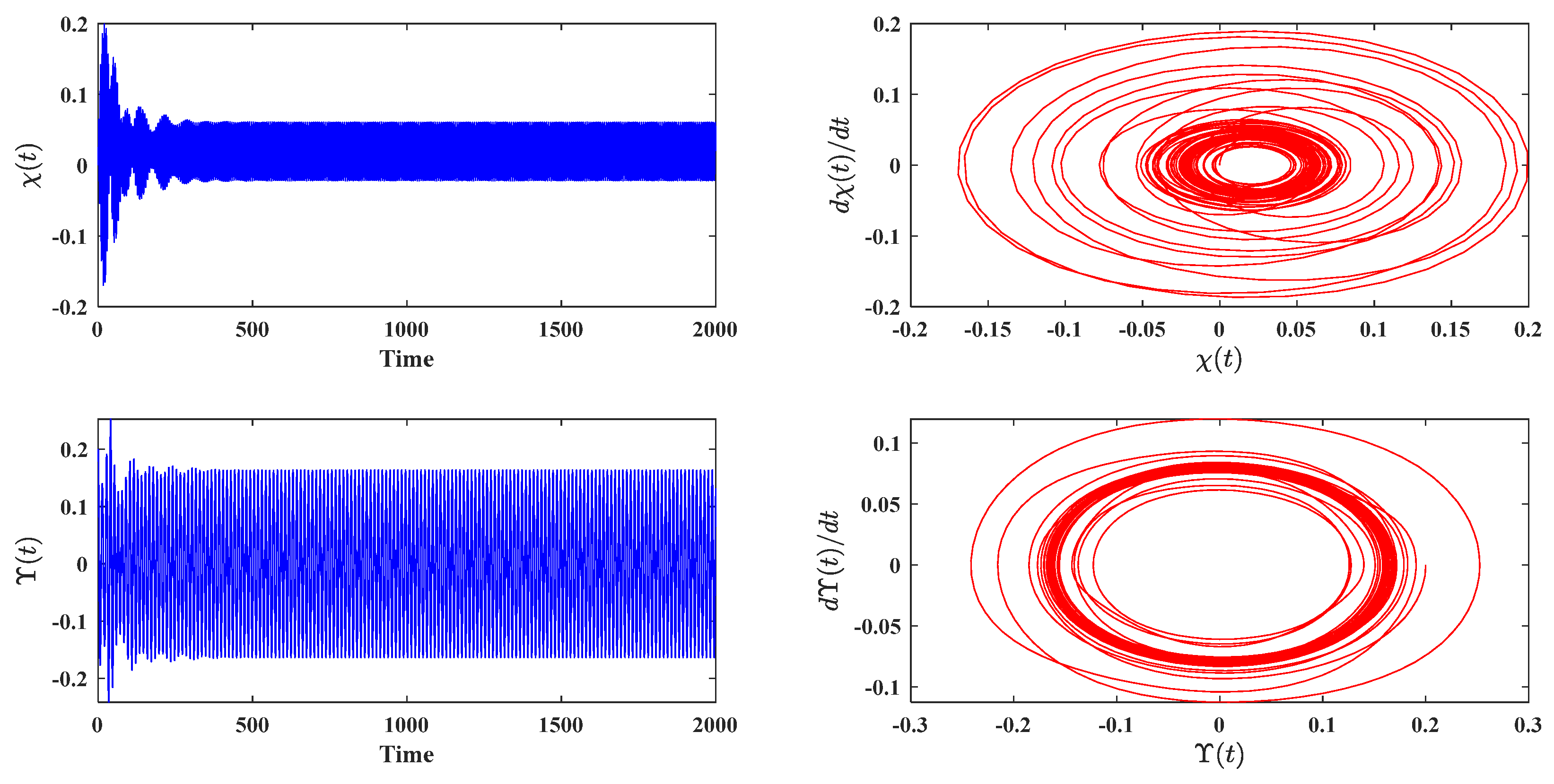
At simultaneous resonance, the van der Pol system with the NSC controller that was supplied ( Λ 1 ϖ 1 and ϖ 1 2 ϖ 2 ) is numerically solved in this part using the RK-4th-order method using the MATLAB (R2014a) computer program (package ode45). The specific values of the equation parameters are as follows: α 1 = 0.04 ,   ϖ 1 = 1 ,   λ = 3.5 ,   β = 2.5 ,   γ = 0.04 ;   f 1 = 0.02 ,   f 2 = 0.05 ,   Λ 1 = ϖ 1 ,   Λ 2 = 2 . The time history of the model without a control mechanism is displayed in Figure 2, which shows that the steady-state amplitude of the system without a controller is within the initial values χ ( 0 ) = 0 , χ ˙ ( 0 ) = 0 , ϒ ( 0 ) = 0.2   and   ϒ ˙ ( 0 ) = 0 . Figure 3 displays the phase-plane and time history for the nonlinear system with NSC under conditions ( Λ 1 ϖ 1 and ϖ 1 2 ϖ 2 ) with parameters G 1 = 1.5 , G 2 = 0.6 , α 2 = 0.008 , ϖ 2 = 0.5 . At t = 500, the controller and main system reach saturation, respectively. Figure 3 shows that the amplitude of the system with NSC decreased to roughly 68.59% of the value without NSC.

5.2. The Effects of Various Parameters

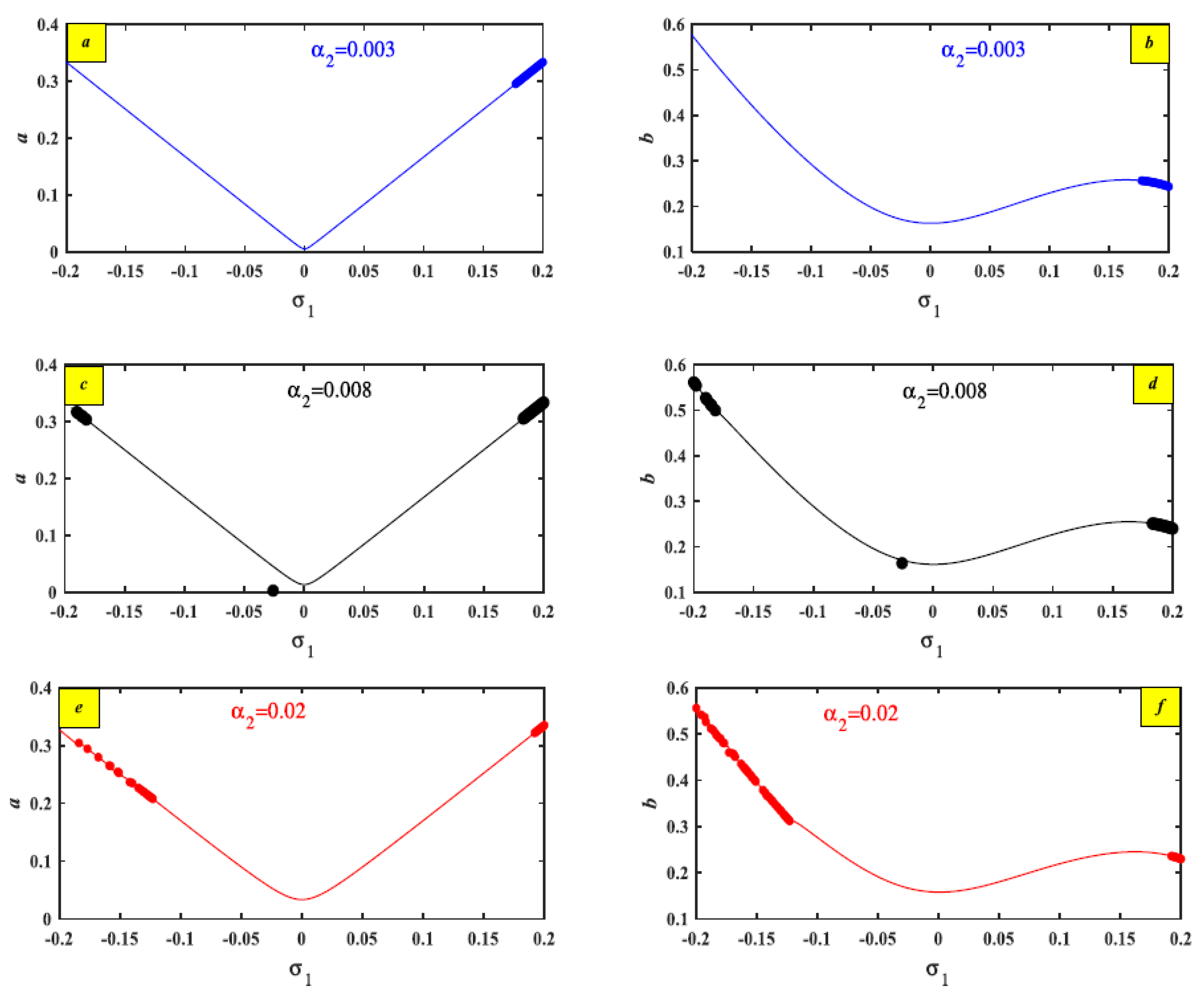
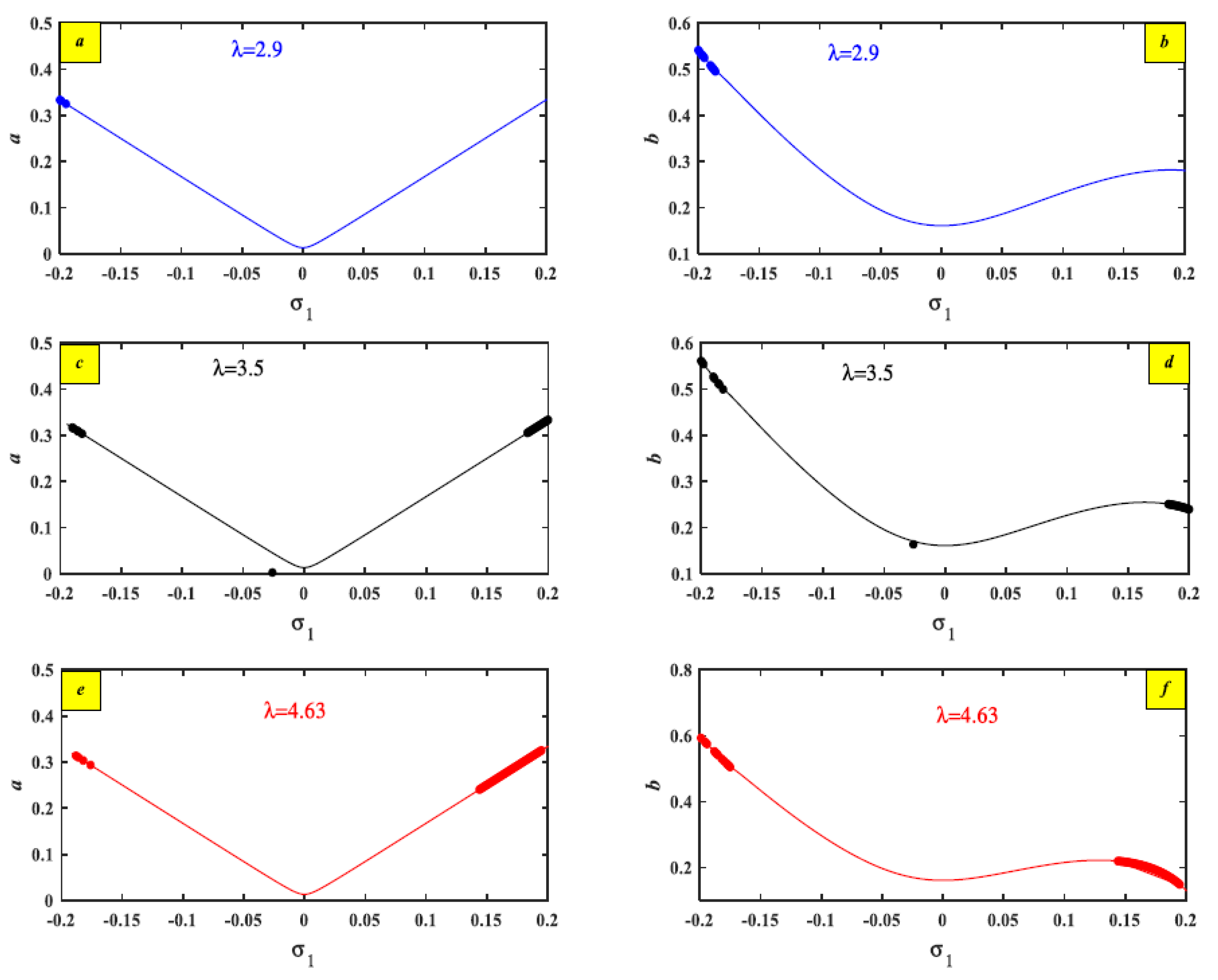
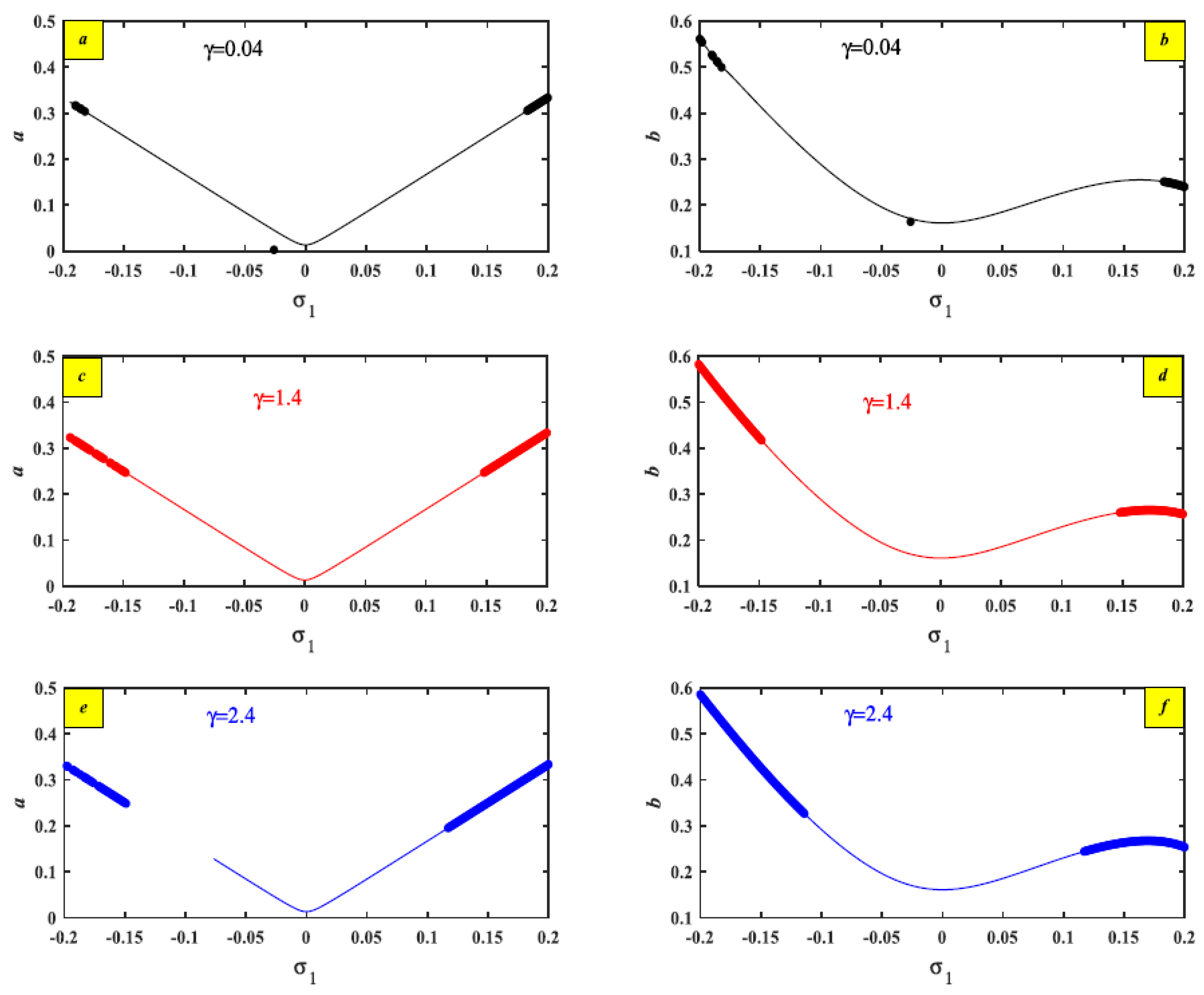
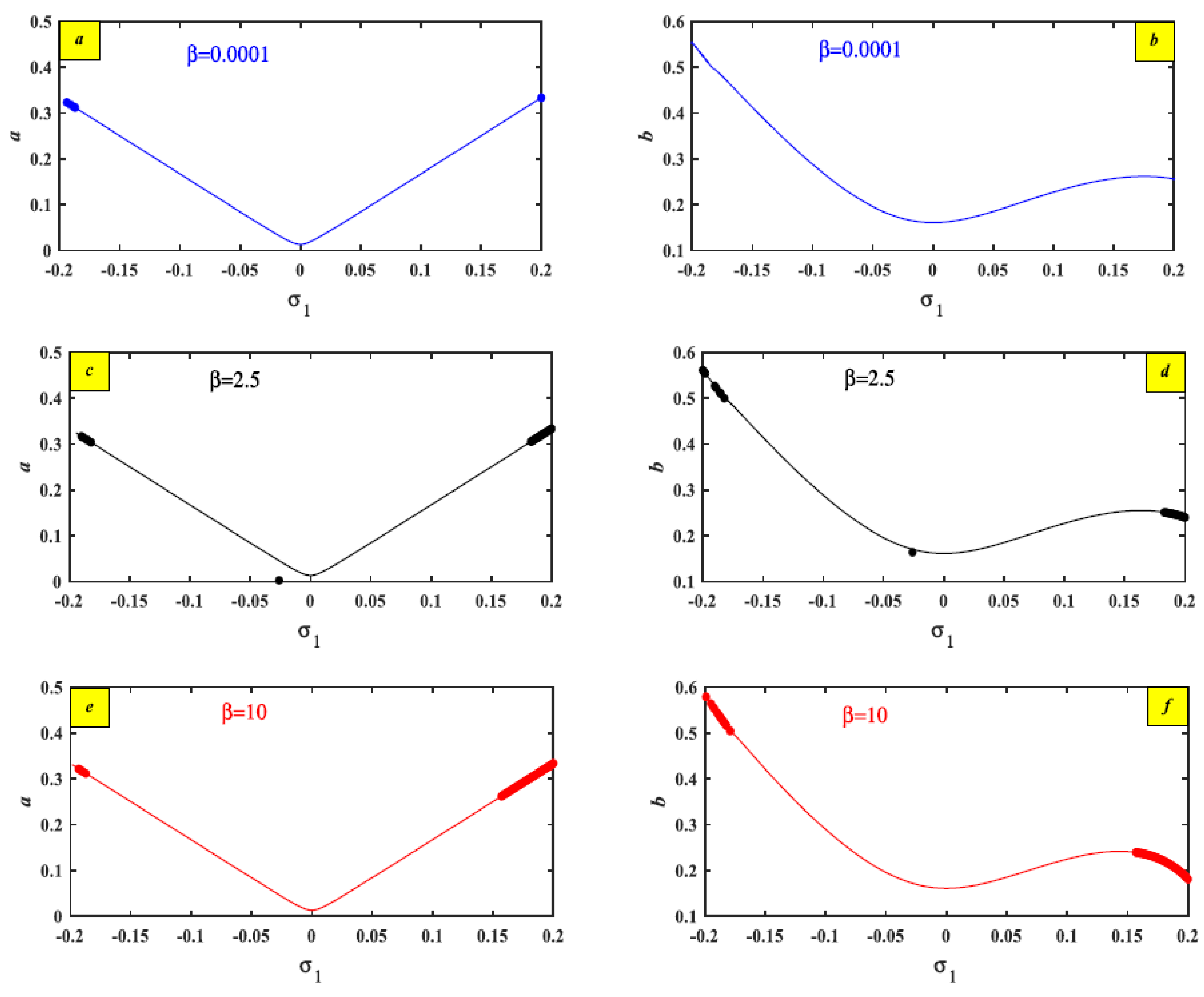
This section examined the steady situation amplitude in the case of 1:2 resonance with respect to the regulated system. We have numerically solved the FREs (28) and (29) using the identical values for the parameters. The results are shown graphically as the steady scenario amplitude a for the system and the NSC controller b against the detuning setting. Following the addition of the NSC, the outputs are shown in Figure 4 as steady scenario amplitudes a and b against the detuning. As shown in Table 1, three representative values were all allocated to each system parameter to examine how they affected the dynamic response. The force amplitude f 1 increased, causing the unstable region to diminish in both system and NSC amplitudes, as shown in Figure 5. As Figure 5a–c illustrate, the system remains unchanged as the force develops. As the values of the damping coefficients ( α 1 and α 2 ) grew, the unstable zone expanded as shown in Figure 6 and Figure 7. Figure 8 demonstrates how increasing the control signal gain G 1 values led to a decrease in the unstable region in the steady scenario amplitude for system a and an increase in the steady scenario for controller b. Figure 9 explains how the primary system’s unstable zone decreased as the control feedback G 2 signal’s values increased. On the other hand, the controller’s steady-state amplitude is increased. Figure 10 demonstrates how the values of ϖ 1 increase the steady scenario amplitudes of the controller and the system. Figure 11, Figure 12 and Figure 13, in that order, illustrate that the unstable region increased by increasing the values of the nonlinear parameters λ , γ , and β . In Figure 14, the steady scenario amplitude for the controller developed as the values of the detuning parameter σ 2 increased, but the steady scenario amplitude for the system shifted to the right.

5.3. Effectiveness of External Excitations

Figure 15 shows the system’s external excitation force increased. Although the amplitude χ t is increased before the addition of the NSC, the effect is not evident at this time due to the tiny values, as illustrated in Figure 15a, because χ t has an amplitude between 0 and 0.2. When the NSC controller is added, as shown in Figure 15b, the system’s amplitude decreases, and the amplitude of χ t falls between 0 and 0.06. As a result, we concluded that the NSC controller effectively reduces the external excitation force. Additionally, the van der Pol motion is described in Figure 16 by increasing the external excitation force. Although the amplitude χ t is increased before the addition of the NSC, the effect is not evident at this time due to the tiny values, as illustrated in Figure 16a, because χ t has an amplitude between 0 and 0.198. When the NSC controller is added, as seen in Figure 16b, the system’s amplitude decreases, and the amplitude of χ t falls between 0 and 0.0592. As a result, we concluded that the NSC controller effectively reduces the external excitation force.

5.4. Important Compassion Results on the System

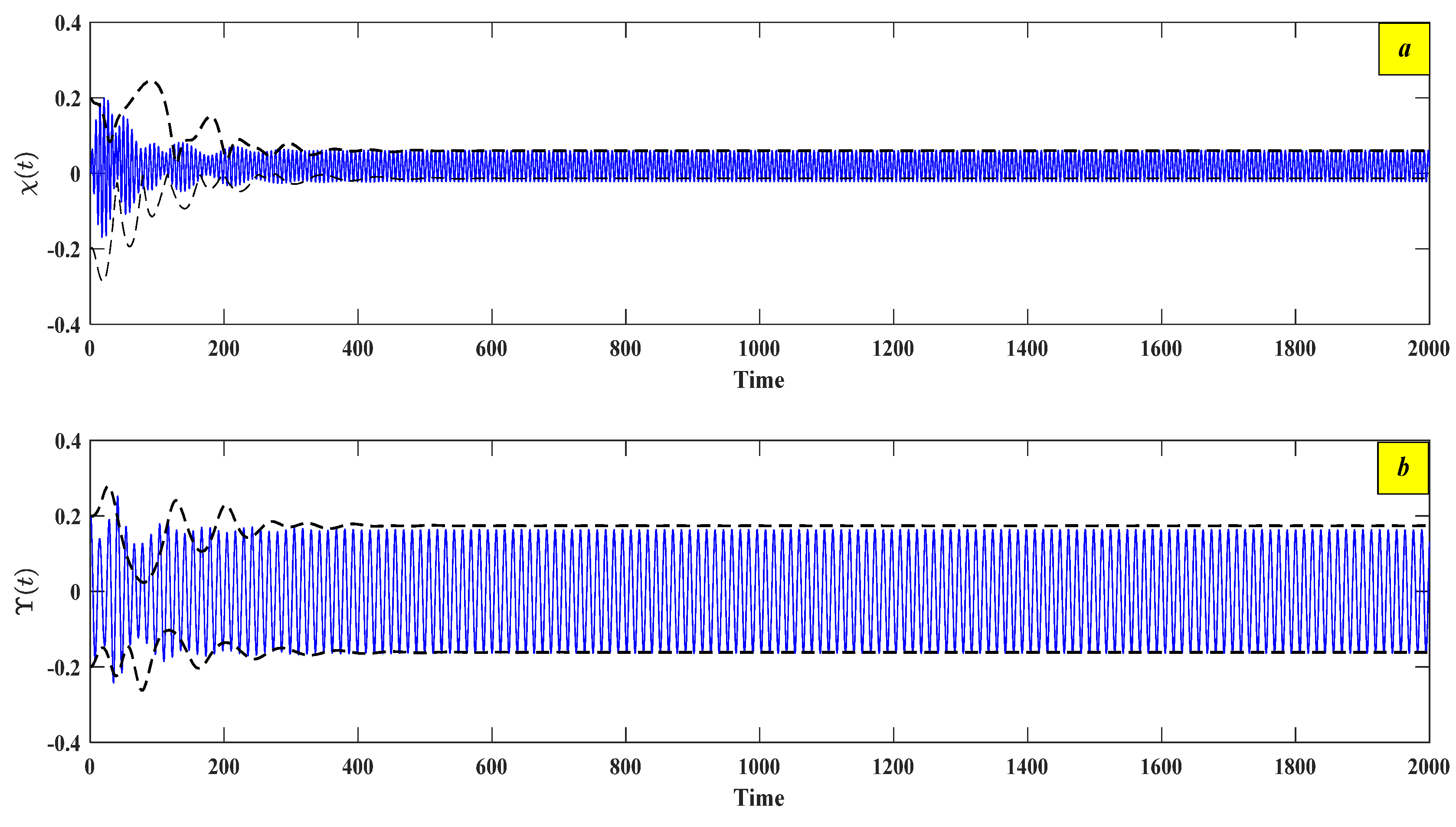
Figure 17 presents a graphical comparison between the approximate analysis of Equations (20)–(23) and the numerical simulation results of Equations (2) and (3). The dashed lines represent the modulation of amplitudes a and b for the full coordinates χ and ϒ , respectively. The solid lines indicate the time response of the vibrations, obtained through numerical modeling using the NSC controller. The figure further illustrates that the AS based on the multiple-scales perturbation technique (MSPT) closely matches the numerical results derived from the Runge–Kutta 4 (RK-4) method. By calculating the errors between AS and NS, we can incorporate both an absolute error ( ζ r ) analysis and the root mean square error (RMSE). Furthermore, this validation has been included in Table 2, which illustrates the MSPT method’s accuracy and convergence characteristics. These modifications improve the clarity of the comparison between the two systems and strengthen the validity of our conclusions.
Figure 18 illustrates the response of the van der Pol–Mathieu–Duffing oscillator with and without control, using low-gain values. Initially, the system exhibits nonlinear oscillations without any control during the time interval t 0 , 250 . At t = 250 , a conventional integral resonant controller (IRC) is applied and remains active until t = 500 . Then, at t = 500 , the IRC controller is deactivated and replaced immediately by the NSC controller, which continues to operate until t = 1500 . As observed in the figure, the IRC controller leads to a slight reduction in vibration amplitude during the interval t 250 , 500 . However, switching to the NSC controller at t = 500 results in a more effective suppression of the system’s vibrations.
The DE of motion that describes the oscillations of the van der Pol with the IRC controller in this manner follows
χ ¨ + ε α 1 χ ˙ ε γ χ 2 χ ˙ + ϖ 1 2 χ + ε λ χ 3 + ε β χ 5 = ε f 1 cos ( Λ 1 t ) + ε χ f 2 cos ( Λ 2 t ) + ε G 1 z
z ˙ + η z = G 2 χ
To achieve the novelty of this work, a comparison is made between the present work and the previous ones in [15,40], as presented in Table 3.

6. Conclusions

By adding a nonlinear saturation controller, the control performance of a van der Pol–Mathieu–Duffing oscillator is improved. When the external excitation force is applied to the primary system, the expected synchronous resonance situation is near; the proposed nonlinear controller NSC has been investigated using a method of different time scales. The stability of the steady-state solution was examined and quantitatively verified using FREs and perturbation analysis. Numerous experiments are conducted to assess the consequences of different controller and system settings. The primary subjects of the numerical findings are the system’s performance and the impact of various parameters. The vibrating system’s amplitude is suppressed from about 0.207 to roughly 0.0601, and the vibrations are decreased by roughly 70.97% compared to their uncontrolled value. The NSC effectiveness E a ( E a = steady-state amplitude of the main system without controller/steady-state amplitude of the main system with controller) is close to 3.44. The measured resonance case is ( Λ 1 ϖ 1 and ϖ 1 2 ϖ 2 ) the worst one.
(1)
Using the NSC technique is the way to drastically reduce the vibration amplitudes of the system.
(2)
The unstable region decreased by increasing the excitation external force amplitude f 1 in both the system and NSC amplitudes.
(3)
The values of the natural frequency increase the steady-state amplitudes of the controller and main system. Furthermore, by raising the damping coefficient values α 1 and α 2 , the unstable zone grew.
(4)
The system’s amplitude fell in the unstable region while the values of the control signal gain G 1 increased in the steady state.
(5)
The steady scenario for the controller increased, but the unstable region for the system decreased by developing the values of the control feedback signal G 2 .
This study focuses primarily on a specific resonance instance and is restricted to weakly nonlinear oscillations. The analysis lacks experimental validation and is purely theoretical and numerical. The model will be expanded to different resonance settings in further studies, and experimental investigations will be conducted to confirm the results.

Author Contributions

A.T.E.-S.: Investigation, methodology, data curation, validation, reviewing, and editing. R.K.H.: Investigation, methodology, formal analysis, reviewing and editing, and funding acquisition. Y.A.A.: Conceptualization, resources, methodology, writing—original draft preparation, visualization, reviewing, and editing. S.S.M.: Formal analysis, validation, investigation, methodology, data curation, conceptualization, validation, reviewing, and editing. S.A.A.: Investigation, methodology, formal analysis, reviewing, and editing. T.A.B.: Methodology, software, validation, data curation, reviewing, and editing. All authors have read and agreed to the published version of the manuscript.

Funding

This work was supported and funded by the Deanship of Scientific Research at Imam Mohammad Ibn Saud Islamic University (IMSIU) (grant number IMSIU-DDRSP2503).

Data Availability Statement

All data generated or analyzed during this study are included in this published article.

Acknowledgments

The authors extend their appreciation to the Deanship of Scientific Research at Imam Mohammad Ibn Saud Islamic University (IMSIU), KSA, for funding this research work through the project number “IMSIU-DDRSP2503”.

Conflicts of Interest

The authors have not revealed any conflicting interests.

Abbreviations

The AbbreviationsThe Meaning
DOFDegrees of freedom.
MSPTMultiple-scale perturbation.
RK-4The fourth-order Runge–Kutta method.
NSCNonlinear saturation controller.
VMDOVan der Pol–Mathieu–Duffing oscillator
DEDifferential equation
ASApproximate solution
NSNumerical solution
RMSERoot mean square error

Appendix A

E 1 = β 24 ϖ 1 2 E 2 = λ A 3 + 5 β A 4 A ¯ i γ A 3 ϖ 1 8 ϖ 1 2 E 3 = f 1 2 ( ϖ 1 2 Λ 1 2 ) E 4 = f 2 2 Λ 2 ( Λ 2 2 ϖ 1 )
E 5 = f 2 2 Λ 2 ( 2 ϖ 1 Λ 2 ) E 6 = G 1 B 2 ( ϖ 1 2 4 ϖ 2 2 ) E 7 = G 1 B B ¯ ϖ 1 2 E 8 = G 2 A B ϖ 1 ( 2 ϖ 2 ϖ 1 ) E 9 = G 2 A B ¯ ϖ 1 ( ϖ 1 2 ϖ 2 )
From Equation (17)
i ϖ 1 ( a ˙ + i a Θ ˙ 1 ) e i Θ 1 = i α 1 2 ϖ 1 a e i Θ 1 + i γ ϖ 1 8 a 3 e i Θ 1 3 λ 8 a 3 e i Θ 1 10 β 32 a 5 e i Θ 1 + f 1 2 e i σ 1 T 1 + G 1 b 2 4 e 2 i Θ 2 i σ 2 T 1
Divided by ϖ 1 e i Θ 1 we get
i ( a ˙ + i a Θ ˙ 1 ) = i α 1 2 a + i γ 1 8 a 3 3 λ 8 ϖ 1 a 3 5 β 16 ϖ 1 a 5 + f 1 2 ϖ 1 e i ( σ 1 T 1 Θ 1 ) + G 1 b 2 4 ϖ 1 e i ( 2 Θ 2 σ 2 T 1 Θ 1 )
Separating real and imaginary parts we get Equation (20) and Equation (21)
From the Equation (18)
i ϖ 2 ( b ˙ + i b Θ 2 ) e i Θ 2 = i α 2 2 ϖ 2 b e i Θ 2 + G 2 4 a b e i ( Θ 1 Θ 2 + σ 2 T 1 )
Divided by ϖ 1 e i Θ 2 we get
i ( b ˙ + i b Θ 2 ) = i α 2 2 b + G 2 4 ϖ 2 a b e i ( Θ 1 2 Θ 2 + σ 2 T 1 )
Separating real and imaginary parts we get Equation (22) and Equation (23)
H 1 = δ 44 δ 33 δ 22 δ 11
H 2 = δ 41 δ 14 δ 42 δ 24 δ 43 δ 34 + δ 44 δ 33 + δ 44 δ 22 + δ 44 δ 11                     δ 31 δ 13 + δ 33 δ 22 + δ 33 δ 11 δ 21 δ 12 + δ 22 δ 11
H 3 = δ 41 δ 14 δ 33 + δ 41 δ 14 δ 22 + δ 42 δ 24 δ 33 + δ 42 δ 24 δ 11 + δ 43 δ 34 δ 22 + δ 43 δ 34 δ 11 + δ 44 δ 31 δ 13           δ 44 δ 33 δ 22 δ 44 δ 33 δ 11 + δ 44 δ 21 δ 12 δ 44 δ 22 δ 11 δ 31 δ 12 δ 23 + δ 31 δ 13 δ 22 + δ 33 δ 21 δ 12           δ 33 δ 22 δ 11 δ 41 δ 12 δ 24 δ 41 δ 13 δ 34 δ 42 δ 21 δ 14 δ 42 δ 23 δ 34 δ 43 δ 31 δ 14
H 4 = δ 41 δ 13 δ 34 δ 22 + δ 42 δ 21 δ 14 δ 33 + δ 42 δ 23 δ 34 δ 11 + δ 43 δ 31 δ 14 δ 22 δ 41 δ 14 δ 33 δ 22 + δ 42 δ 24 δ 31 δ 13         δ 42 δ 24 δ 33 δ 11 + δ 43 δ 34 δ 21 δ 12 δ 43 δ 34 δ 22 δ 11 + δ 44 δ 31 δ 12 δ 23 δ 44 δ 31 δ 13 δ 22 δ 44 δ 33 δ 21 δ 12         + δ 44 δ 33 δ 22 δ 11 δ 41 δ 12 δ 23 δ 34 δ 42 δ 21 δ 13 δ 34 δ 42 δ 23 δ 31 δ 14 δ 43 δ 31 δ 12 δ 24 + δ 41 δ 12 δ 24 δ 33

References

  1. Xu, J.; Chung, K. Effects of time delayed position feedback on a van der Pol–Duffing oscillator. Phys. D Nonlinear Phenom. 2003, 180, 17–39. [Google Scholar] [CrossRef]
  2. El-Ganaini, W.A.; Saeed, N.A.; Eissa, M. Positive position feedback (PPF) controller for suppression of nonlinear system vibration. Nonlinear Dyn. 2013, 72, 517–537. [Google Scholar] [CrossRef]
  3. Wen, S.; Shen, Y.; Li, X.; Yang, S. Dynamical analysis of Mathieu equation with two kinds of van der Pol fractional-order terms. Int. J. Non-Linear Mech. 2016, 84, 130–138. [Google Scholar] [CrossRef]
  4. Roy, S.; Das, D.; Banerjee, D. Vibrational resonance in a bistable van der Pol-Mathieu–Duffing oscillator. Int. J. Non-Linear Mech. 2021, 135, 103771. [Google Scholar] [CrossRef]
  5. Ren, Y.; Ma, W. Dynamic Analysis and PD Control in a 12-Pole Active Magnetic Bearing System. Mathematics 2024, 12, 2331. [Google Scholar] [CrossRef]
  6. Hamed, Y.S.; Alotaibi, H.; El-Zahar, E.R. Nonlinear vibrations analysis and dynamic responses of a vertical conveyor system controlled by a proportional derivative controller. IEEE Access 2020, 8, 119082–119093. [Google Scholar] [CrossRef]
  7. Jamshidi, R.; Collette, C. Optimal negative derivative feedback controller design for collocated systems based on H2 and H method. Mech. Syst. Signal Process. 2022, 181, 109497. [Google Scholar] [CrossRef]
  8. Jun, L.; Hongxing, H.; Rongying, S. Saturation-based active absorber for a non-linear plant to a principal external excitation. Mech. Syst. Signal Process. 2007, 21, 1489–1498. [Google Scholar] [CrossRef]
  9. Zhang, Y.; Li, J.; Zhu, S.; Zhao, H. Bifurcation and chaos detection of a fractional Duffing-van der Pol oscillator with two periodic excitations and distributed time delay. Chaos 2023, 33, 083153. [Google Scholar] [CrossRef]
  10. Fahsi, A.; Belhaq, M.; Lakrad, F. Suppression of hysteresis in a forced van der Pol-Duffing oscillator. Commun. Nonlinear Sci. Numer. Simul. 2008, 14, 1609–1616. [Google Scholar] [CrossRef]
  11. Yaman, M. Direct and parametric excitation of a nonlinear cantilever beam of varying orientation with time-delay state feedback. J. Sound Vib. 2009, 324, 892–902. [Google Scholar] [CrossRef]
  12. Alhazza, K.A.; Majeed, M.A. Free vibrations control of a cantilever beam using combined time delay feedback. J. Vib. Control 2012, 18, 609–621. [Google Scholar] [CrossRef]
  13. Cai, G.P.; Yang, S.X. A discrete optimal control method for a flexible cantilever beam with time delay. J. Vib. Control 2006, 12, 509–526. [Google Scholar] [CrossRef]
  14. Mirafzal, S.H.; Khorasani, A.M.; Ghasemi, A.H. Optimizing time delay feedback for active vibration control of a cantilever beam using a genetic algorithm. J. Vib. Control 2016, 22, 4047–4061. [Google Scholar] [CrossRef]
  15. Kashchenko, S. Van der Pol equation with a large feedback delay. Mathematics 2023, 11, 1301. [Google Scholar] [CrossRef]
  16. Temnaya, O.S.; Safin, A.R.; Kravchenko, O.V.; Nikitov, S.A. Influence of nonlinearity on an exceptional point in a system of coupled duffing oscillators. J. Commun. Technol. Electron. 2023, 68, 979–982. [Google Scholar] [CrossRef]
  17. Kandil, A.; Hamed, Y.S.; Abualnaja, K.M.; Awrejcewicz, J.; Bednarek, M. 1/3 order subharmonic resonance control of a mass damper-spring model via cubic-position negative-velocity feedback. Symmetry 2022, 14, 685. [Google Scholar] [CrossRef]
  18. Ramini, A.H.; Hajjaj, A.Z.; Younis, M.I. Tunable resonators for nonlinear modal interactions. Sci. Rep. 2016, 6, 34717. [Google Scholar] [CrossRef] [PubMed]
  19. Li, J.; Li, X.; Hua, H. Active nonlinear saturation-based control for suppressing the free vibration of a self-excited plant. Commun. Nonlinear Sci. Numer. Simulation 2010, 15, 1071–1079. [Google Scholar] [CrossRef]
  20. Warminski, J.; Bochenski, M.; Jarzyna, W.; Filipek, P.; Augustyniak, M. Active suppression of nonlinear composite beam vibrations by selected control algorithms. Commun. Nonlinear Sci. Numer. Simul. 2011, 16, 2237–2248. [Google Scholar] [CrossRef]
  21. Nayfeh, A.H.; Chin, C.M.; Pratt, J. Perturbation methods in nonlinear dynamics applications to machining dynamics. J. Manuf. Sci. Eng. 1997, 119, 485–493. [Google Scholar] [CrossRef]
  22. Mickens, R.E. Oscillations in Planar Dynamic Systems; World Scientific: Singapore, 1996; Volume 37. [Google Scholar] [CrossRef]
  23. Moatimid, G.M. Stability Analysis of a Parametric Duffing Oscillator. J. Eng. Mech. 2020, 146, 05020001. [Google Scholar] [CrossRef]
  24. Barron, M.A. Stability of a ring of coupled van der Pol oscillators with non-uniform distribution of the coupling parameter. J. Appl. Res. Technol. 2016, 14, 62–66. [Google Scholar] [CrossRef]
  25. Orlov, V.; Chichurin, A. The influence of the perturbation of the initial data on the analytic approximate solution of the Van der Pol equation in the complex domain. Symmetry 2023, 15, 1200. [Google Scholar] [CrossRef]
  26. Kakou, P.; Gupta, S.K.; Barry, O. A nonlinear analysis of a Duffing oscillator with a nonlinear electromagnetic vibration absorber-inerter for concurrent vibration mitigation and energy harvesting. Nonlinear Dyn. 2024, 112, 5847–5862. [Google Scholar] [CrossRef]
  27. Bauomy, H.S.; EL-Sayed, A.T. Mixed controller (IRC+NSC) involved in the harmonic vibration response cantilever beam model. Meas. Control 2020, 53, 1954–1967. [Google Scholar] [CrossRef]
  28. Bauomy, H.S.; EL-Sayed, A.T. Act of nonlinear proportional derivative controller for MFC laminated shell. Phys. Scr. 2020, 95, 095210. [Google Scholar] [CrossRef]
  29. Bauomy, H.S.; EL-Sayed, A.T. A new six-degrees of freedom model designed for a composite plate through PPF controllers. Appl. Math. Model. 2020, 88, 604–630. [Google Scholar] [CrossRef]
  30. Bauomy, H.S. New controller (NPDCVF) outcome of FG cylindrical shell structure. Alex. Eng. J. 2022, 61, 1779–1801. [Google Scholar] [CrossRef]
  31. Binatari, N.; van Horssen, W.T.; Verstraten, P.; Adi-Kusumo, F.; Aryati, L. On the multiple time-scales perturbation method for differential-delay equations. Nonlinear Dyn. 2024, 112, 8431–8451. [Google Scholar] [CrossRef]
  32. Kevorkian, J.; Cole, J.D. The Method of Multiple Scales for Ordinary Differential Equations. In Multiple Scale and Singular Perturbation Methods. Applied Mathematical Sciences; Springer: New York, NY, USA, 1996; Volume 114. [Google Scholar] [CrossRef]
  33. Nayfeh, A.H. Perturbation Methods; Wiley: New York, NY, USA, 2000. [Google Scholar] [CrossRef]
  34. Dukkipati, R.V. Solving Vibration Analysis Problems Using MATLAB; New Age International Pvt Ltd. Publishers: New Delhi, India, 2007. [Google Scholar]
  35. Alluhydan, K.; Amer, Y.A.; EL-Sayed, A.T.; Agwa, M.M. Stability and Control of Car Dynamics with a Quarter Model via a Novel Simple Harmonic Hump under External Force. Mathematics 2024, 12, 3046. [Google Scholar] [CrossRef]
  36. Amer, T.S.; Bahnasy, T.A.; Abosheiaha, H.F.; Elameer, A.S.; Almahalawy, A. The stability analysis of a dynamical system equipped with a piezoelectric energy harvester device near resonance. J. Low Freq. Noise Vib. Act. Control 2025, 44, 382–410. [Google Scholar] [CrossRef]
  37. Arena, A.; Lepidi, M. Nonlinear wave propagation in a two-dimensional lattice model of textile metamaterials. Nonlinear Dyn. 2025, 1–22. [Google Scholar] [CrossRef]
  38. Razzaq, M.A.; Rocha, R.T.; Tian, Y.; Towfighian, S.; Masri, S.F.; Younis, M.I. Nonparametric identification of a MEMS resonator actuated by levitation forces. Int. J. Non-Linear Mech. 2024, 160, 104633. [Google Scholar] [CrossRef]
  39. Erturk, V.S.; Rath, B.; Al-Khader, T.M.; Alshaikh, N.; Mallick, P.; Asad, J. Two-dimensional coupled asymmetric van der Pol oscillator. Eur. J. Pure Appl. Math. 2024, 17, 1254–1264. [Google Scholar] [CrossRef]
  40. Abohamer, M.K.; Amer, T.S.; Galal, A.A.; Darweesh, M.A.; Arab, A.; Bahnasy, T.A. On chaotic behavior, stability analysis, and vibration control of the van der Pol–Mathieu–Duffing oscillator under parametric force and resonance. J. Low Freq. Noise Vib. Act. Control 2025, 1–17. [Google Scholar] [CrossRef]
  41. Cui, W.; Zhao, L.; Ge, Y.; Xu, K. A generalized van der Pol nonlinear model of vortex-induced vibrations of bridge decks with multistability. Nonlinear Dyn. 2024, 112, 259–272. [Google Scholar] [CrossRef]
  42. Elnady, A.O.; Newir, A.; Ibrahim, M.A. Novel approach for solving higher-order differential equations with applications to the Van der Pol and Van der Pol–Duffing equations. Beni-Suef Univ. J. Basic Appl. Sci. 2024, 13, 29. [Google Scholar] [CrossRef]
  43. Herişanu, N.; Marinca, V. An iteration procedure with application to Van der Pol oscillator. Int. J. Nonlinear Sci. Numer. Simul. 2009, 10, 353–362. [Google Scholar] [CrossRef]
  44. Ali, A.H.; Amir, M.; Rahman, J.U.; Raza, A.; Arif, G.E. Design of Morlet Wavelet Neural Networks for Solving the Nonlinear Van der Pol–Mathieu–Duffing Oscillator Model. Computers 2025, 14, 14. [Google Scholar] [CrossRef]
  45. Zhao, F.; Ma, X.; Cao, S. Periodic bursting oscillations in a hybrid Rayleigh–Van der Pol–Duffing oscillator. Nonlinear Dyn. 2023, 111, 2263–2279. [Google Scholar] [CrossRef]
Figure 1. A flowchart for the system model with NSC.
Actuators 14 00427 g001
Figure 2. The behavior of the uncontrolled system in the primary resonance scenario.
Actuators 14 00427 g002
Figure 3. The system’s and NSC’s actions in a simultaneous resonance case ( Λ 1 ϖ 1 and ϖ 1 2 ϖ 2 ).
Actuators 14 00427 g003
Figure 4. Frequency–response curves for (a) the primary system and (b) the NSC. ( α 1 = 0.04 , ϖ 1 = 1 ,   λ = 3.5 ,   β = 2.5 ,   γ = 0.04 ,   f 1 = 0.02 ,   α 2 = 0.008 ,   ϖ 2 = 0.5 ,   G 1 = 1.5 ,   G 2 = 0.6 . ).
Actuators 14 00427 g004
Figure 5. (a,c,e) The primary system amplitude and (b,d,f) the NSC amplitude are affected by the excitation force f 1 .
Actuators 14 00427 g005
Figure 6. The impact of the damping coefficient on (a,c,e) the primary system and (b,d,f) NSC.
Actuators 14 00427 g006
Figure 7. Impact of damping coefficients α 2 on (a,c,e) the primary system and (b,d,f) NSC.
Actuators 14 00427 g007
Figure 8. The impact of control gain G 1 on (a,c) the primary system and (b,d) NSC.
Actuators 14 00427 g008
Figure 9. The impact of feedback control gain G 2 on (a) the primary system and (b) NSC.
Actuators 14 00427 g009
Figure 10. (a) The primary system and (b) NSC as a result of the natural frequency ϖ 1 = 2 ϖ 2 .
Actuators 14 00427 g010
Figure 11. The main system and the NSC are affected by the nonlinear parameter λ .
Actuators 14 00427 g011
Figure 12. Nonlinear parameter γ effects on (a,c,e) the primary system and (b,d,f) NSC.
Actuators 14 00427 g012
Figure 13. (a,c,e)The main system and (b,d,f) NSC are affected by the nonlinear parameter β .
Actuators 14 00427 g013
Figure 14. The significance of the detuning parameter σ 2 on (a) the primary system and (b) NSC.
Actuators 14 00427 g014
Figure 15. The effects of external force excitation f 1  (a) before control (b) after control.
Actuators 14 00427 g015
Figure 16. The effects of external force excitation f 2  (a) before control (b) after control.
Actuators 14 00427 g016
Figure 17. Comparison graph between MSPT (dashed lines) and RK-4 (solid lines) for both amplitudes of (a) the main system and (b) NSC control.
Actuators 14 00427 g017
Figure 18. The effects of different controllers on the van der Pol–Mathieu–Duffing oscillator.
Actuators 14 00427 g018
Table 1. The values system parameters on the dynamic response.
SymbolDescriptionValue 1
(Basic)
Value 2Value 3Figures
f 1 Excitation force0.020.0170.06Figure 5
α 1 Damping coefficient of the system0.040.0080.08Figure 6
α 2 Damping coefficient0.0080.020.003Figure 7
G 1 Control gain1.50.642.6Figure 8
G 2 Feedback control gain0.60.550.4Figure 9
ϖ 1 = 2 ϖ 2 Nature frequency11.10.94Figure 10
λ Nonlinear term3.52.94.63Figure 11
γ Nonlinear term0.041.42.4Figure 12
β Nonlinear term2.50.000110Figure 13
σ 2 Detuning parameter00.05−0.03Figure 14
Table 2. Absolute error ( ζ r ) between the NS and the AS.
With NSC ControlWithout Control
TASNS ζ r ASNS ζ r
8000.05460.048950.00570.14720.14810.0009
8500.01630.021030.00470.12170.14810.0264
9000.07110.079720.00860.18910.17630.0128
9500.0650.067360.00240.12620.12790.0017
10000.05520.051490.00370.15600.14980.0062
10500.05750.060170.00270.18660.18730.0007
11000.05940.052390.00700.20430.23170.0274
11500.05680.058120.00130.20580.21130.0055
12000.05050.061020.01050.19280.18970.0031
12500.04170.050160.00850.16640.16720.0008
13000.03180.032140.00030.12870.12970.0010
13500.02180.023160.00140.18220.18310.0009
14000.01110.012130.00100.23010.23250.0024
14500.00860.010030.00140.22410.22260.0015
15000.00610.008320.00220.17690.17830.0014
RMSE = 0.0052RMSE = 0.0107
Table 3. Comparison between the current work and previous ones in [15,40].
No.Comparison ItemsThe Current StudyThe Examined Work in [15]The Investigated Work in [40]
1DOF1 DOF1 DOF1 DOF
2ASAS are acquired using MSPTThe nonlocal dynamics procedure with a large delayThe AS are obtained by MSPT
3Resonance caseSimultaneous primary and internalNot investigatedSubharmonic
4NSNS are obtained from RK-4The numerical simulation is not achievedThe NS are achieved
5Stability areaThe stability and instability areas are investigated according to the amplitude’s resonance curvesAmplitude’s resonance curves are not presentedThe stability boundaries are drawn
6Parameters’ effectThe parameters affecting amplitudes are plottedNot mapped out
7Feedback controlNSC control is usedDoes not existDisplacement–velocity feedback controller is used
8Diagram of the time history of a solution and phase planThe time history and phase plan are drawn for all cases with and without controlNot presentedNot graphed
9Controller effectivenessThe controller’s effectiveness is investigatedDoes not existNot investigated
Disclaimer/Publisher’s Note: The statements, opinions and data contained in all publications are solely those of the individual author(s) and contributor(s) and not of MDPI and/or the editor(s). MDPI and/or the editor(s) disclaim responsibility for any injury to people or property resulting from any ideas, methods, instructions or products referred to in the content.