1. Introduction
Increasing demands for reducing energy consumption, noise levels, and environmental protection are decisive factors for the modern development of hydraulic drive and control technology. By using hydraulic systems with volumetric control of the velocity of hydraulic motors, it is possible to realize energy-efficient drives. The energy consumption can be reduced up to 80% compared to conventional hydraulic drives using throttle control. This also depends on the operating cycle of the machine. The technical and economic analysis of a number of machines with hydraulic drives shows that volumetric control is appropriate for power higher than 2–4 kW or special applications [
1].
There are three types of volumetric control for industrial applications [
2,
3,
4]:
A variable displacement pump equipped with a hydro-mechanical controller, which is driven by an asynchronous electric motor with a constant rotation frequency. In this case, the regulation of the main energy parameters (flow rate and pressure) is carried out by the pump controller, and the electric motor only converts the electrical energy into mechanical energy.
A variable displacement pump with proportional electrical controller, driven by an asynchronous electric motor with a constant rotation frequency. In this case, the energy transfer and regulation in the system are carried out hydraulically again, but the hydro-mechanical controller is replaced by an electronically controlled proportional valve.
A fixed displacement pump with frequency control, which is driven by an asynchronous or servomotor with a variable rotation frequency. In this case, only the energy transfer in the system is carried out hydraulically. The pump converts the mechanical energy from the electric motor into hydraulic energy. The electrical part of the drive has two main purposes: supplying electrical energy and regulating the energy parameters (flow rate and pressure) in the system by changing the rotation frequency of the electric motor, using a frequency inverter. It is pertinent to note that when the speed of the electric drive motor shaft changes, not only does the pump capacity change, but the frequency of the capacity pulsation and pressure pulsation also changes. These are important changes that affect the stable operation of the hydraulic system [
5].
The listed types of volumetric control are summarized for industrial applications, since in hydraulic drives for mobile applications, there are additional requirements and prerequisites relating to the operation of the pumps in a closed circuit (hydrostatic transmissions), and pumps are driven by a combustion engine or electric motor [
6].
With the introduction of the second of the listed types, volumetric control into the practice of hydraulic drives, in which the hydro-mechanical controller of the pump displacement volume is replaced by an electronically controlled proportional valve, the regulation possibilities are also increased [
7,
8,
9]. On the one hand, feedback is implemented both in terms of velocity and changes in the external load that act on the executive hydraulic cylinder or motor (load-sensing). On the other hand, various control algorithms can be applied [
10]. This combination leads to an additional increase in energy efficiency.
Modern control theory is focused on the development of embedded and real-time control systems [
11,
12], which use both classical (PID) [
13] and advanced (LQR, H∞, μ) [
14,
15,
16,
17,
18,
19,
20,
21,
22,
23,
24,
25,
26,
27] control algorithms. The combination of load-sensing and real-time digital controller is a prerequisite for the development of adaptive controllers [
28,
29,
30,
31,
32,
33,
34,
35,
36,
37,
38].
The volumetric control hydraulic drives most widely used axial piston pumps. This is a consequence of a number of their advantages, some of which are high power density, compactness, higher operating pressure (up to 40–45 MPa), higher rotation frequency (up to 4500 min
−1), open and closed circulation pump design, repairability, etc. [
1,
3]. This motivates several researchers and practitioners, including the authors of the present article, to direct their developments towards real-time displacement volume control of axial piston pumps using digital adaptive control algorithms. Another rapidly developing area of research on axial piston pumps using modern control theory is focused on their fault diagnosis and condition monitoring [
39,
40,
41].
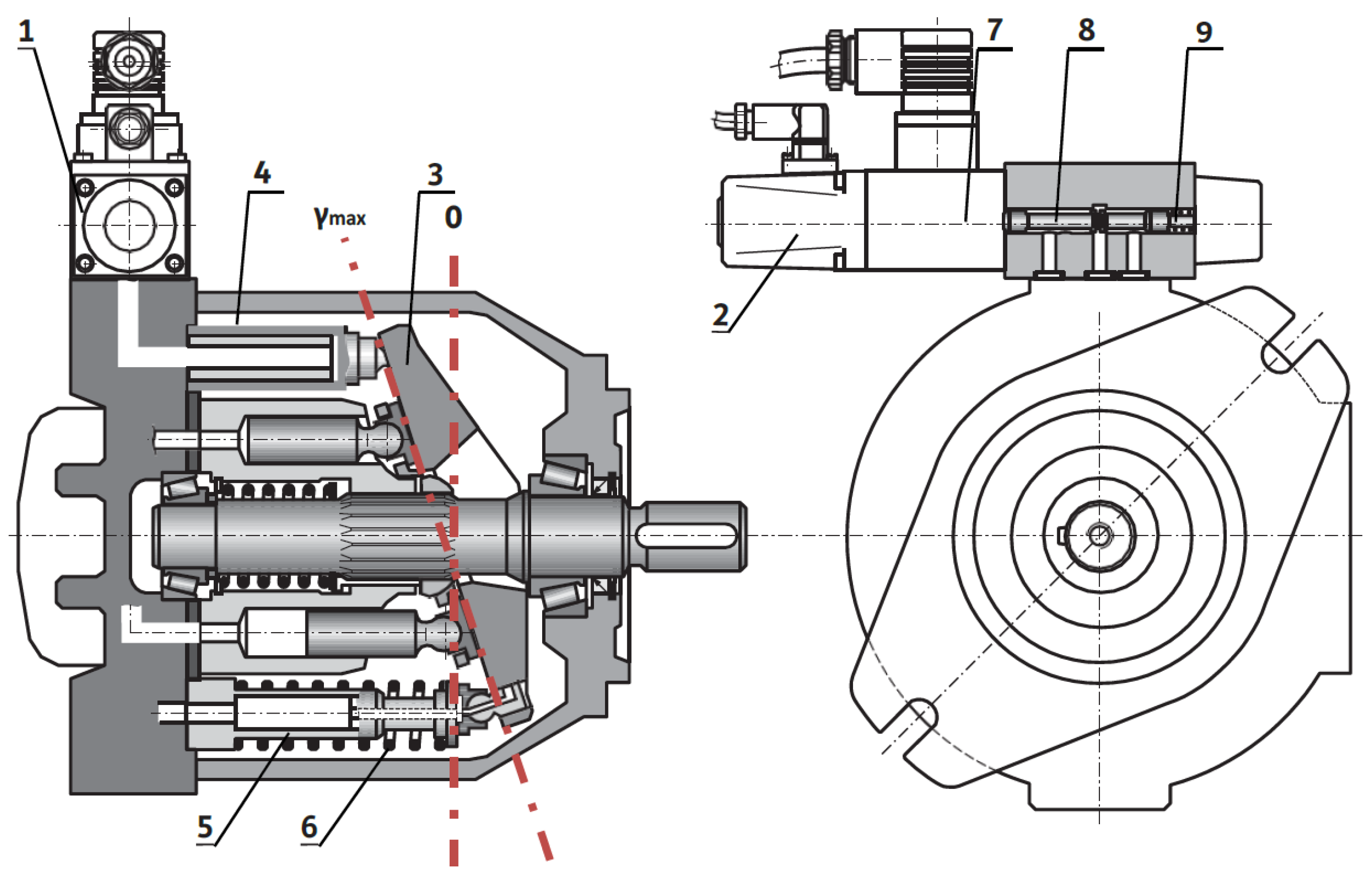
The main goal of this article is to design a gain scheduling (adaptive) proportional–integral (PI) controller. The pump is intended for open circuit hydraulic drive applications without “secondary control”. In this type of pump, the displacement volume depends on the swash plate swivel angle. The change in this angle is carried out by a hydraulically actuating mechanism consisting of an actuating piston and a counter-piston. The actuating piston drives the swash plate by a pressure signal from a control device, and the counter-piston counteracts it by spring. The classic control device of the actuation piston is a hydro-mechanical type, which can realize different control laws (by pressure, flow rate, or power). In the present development, it is replaced by an electronically controlled proportional spool valve. The proportional valve determines the swashplate swivel angle by means of the actuating piston. The displacement volume respective to the flow rate is proportional to the swash plate swivel angle. The adaptive PI controller is designed based on a new linear (LPV) parameter-varying mathematical model. This model is estimated and validated from experimental data for various loading modes by an identification procedure. The gain of the model depends on the current loading of the axial piston pump. The pump loading can be investigated by pump pressure or pump flow rate. In the developed model, static gain is chosen as a function of the steady-state value of axial piston pump flow rate, due to the presence of noise in the pump pressure signal. To conduct the experimental study, the authors used an existing laboratory test setup, enabling a real-time function of the control system via USB/CAN network. The developed controller is realized on a rapid prototyping system. For various loading conditions, real-time experiments are conducted. The designed control system achieves a high quality of control for a wide working range of the pump. The obtained results with the adaptive PI controller are compared with those obtained by other classical PI controllers. The comparison analyses of the experimental results show the advantages of the adaptive PI controller and confirm the possibility of its implementation in a real-time control system of different types of variable displacement hydraulic pumps.
The general contributions of this article are as follows:
The developed simple LPV model of an axial piston pump in which the static gain is a function of the steady-state value of the pump flow rate.
Designed real-time gain-scheduling PI controller based on an LPV model. This controller significantly enhances the performance of displacement volume regulation in swash plate-type axial piston pumps. It is implemented in a conventional digital device.
Replacing the traditional hydro-mechanical controller with an electronically controlled proportional spool valve, the system enables more flexible and precise control over the pump’s output.
Experimental results obtained through rapid prototyping and real-time testing confirm that the adaptive PI controller consistently outperforms the classical PI controller across all evaluated loading conditions.
This article is organized as follows:
Section 2 presents the plant description and rapid prototyping system for real-time controllers. In
Section 3, the gain scheduling adaptive controller design is shown,
Section 4 presents the experimental results obtained with the designed controller, and
Section 5 details the conclusions.
3. Gain Scheduling Adaptive Controller Design
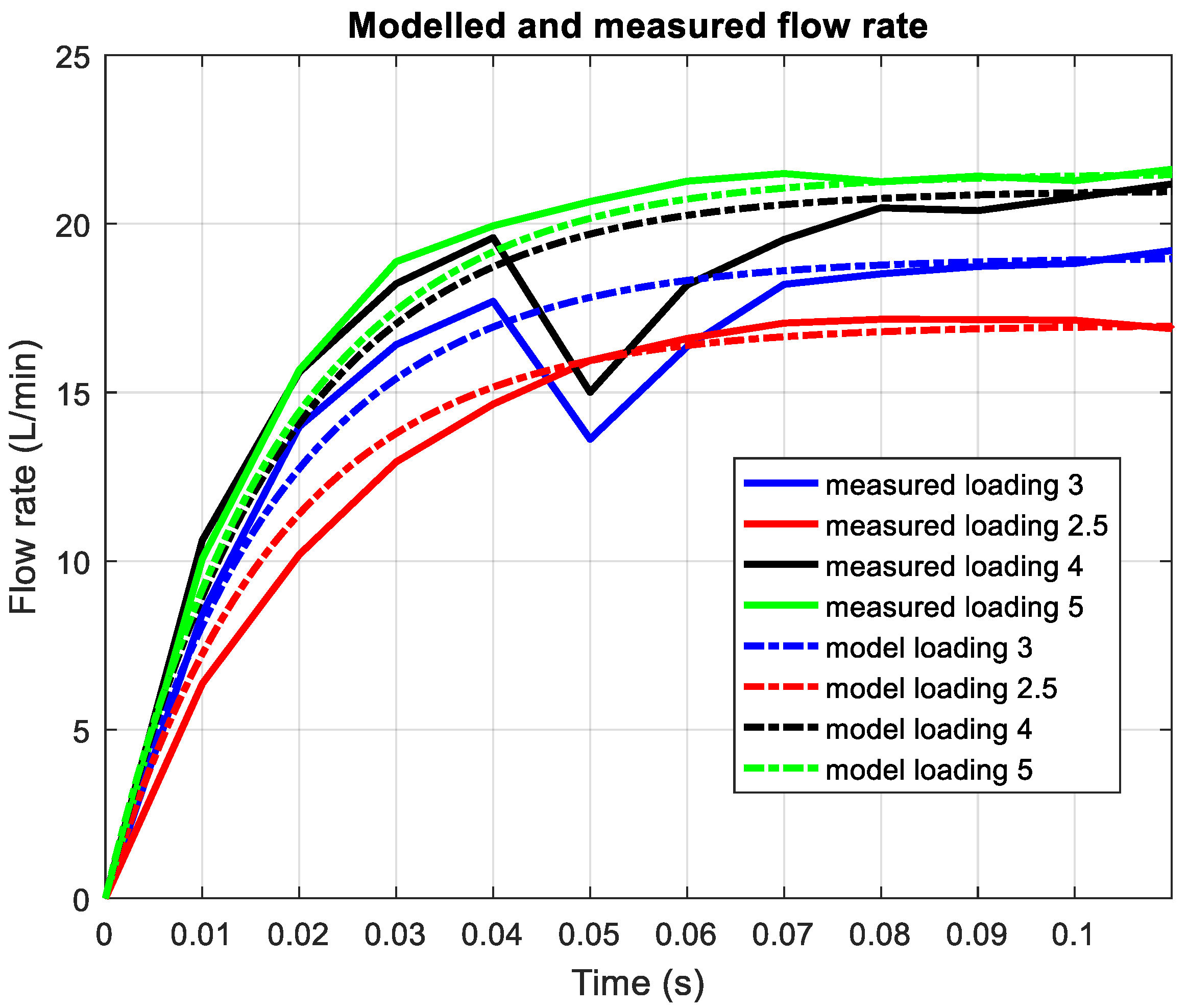
The experiments conducted with the axial piston pump show the dependence of the static gain on the load disturbance. When the load changes fast, the gain coefficient changes fast too. This motivates us to synthesize an adaptive controller. It is well known that in such cases, the most suitable approach for control is gain scheduling adaptive control. The load disturbance is immeasurable, which is why another quantity is needed to determine the current loading and current values of the controller parameters. The load is related to the pressure and to the flow rate of the axial piston pump. When the load increases, the axial piston pump output pressure increases, and the flow rate decreases. However, the pressure is very noisy and is unsuitable for use in determining the parameters of the controller. It affects the swivel in the pump. Thus, for a given pressure, the flow rate setpoint cannot be arbitrary and has a limit. This allows us to derive a relationship between the load and the flow rate set point (desired steady-state value). In this way, the dependence of the gain coefficient of the axial piston pump on the flow rate set point can be obtained. The main aim is to develop a linear parametric-varying model in which the static gain depends on the flow rate reference signal. In order to develop a sufficiently simple model, an experiment was conducted to measure the flow rate transient response at different loads. In all experiments, a step input signal with an amplitude of 100 mV is applied to the axial piston pump. In
Figure 4, the measured flow rate transient responses for different loadings are presented. It is estimated from experimental data (
Figure 4) that the static gain
takes the values 0.13, 0.142, 0.17, 0.188, 0.20, 0.215 for loadings, 1.5, 2, 2.5, 3, 4, and 5, respectively. As can be seen, the settling time of all transient responses is almost the same. Thus, the plant dynamics can be described with a simple first-order model, as follows:
where
is the time constant and
is the static gain which depends on loading current value. For example, for loading 3, the static gain takes a value of 0.188. In
Figure 5, for various loadings, the output of model (1) and the measured flow rate are presented. The results show that the LPV model (1) describes axial piston dynamics sufficiently well.
It is established experimentally that due to physical considerations and the physical limitations of the axial piston pump, the low level of flow-rate set point can take values between 12 and 22 when the load changes from a minimum value of 1.5 to a maximum value of 5. This allows us to derive the following approximate dependence between the gain coefficient and the flow rate reference
.
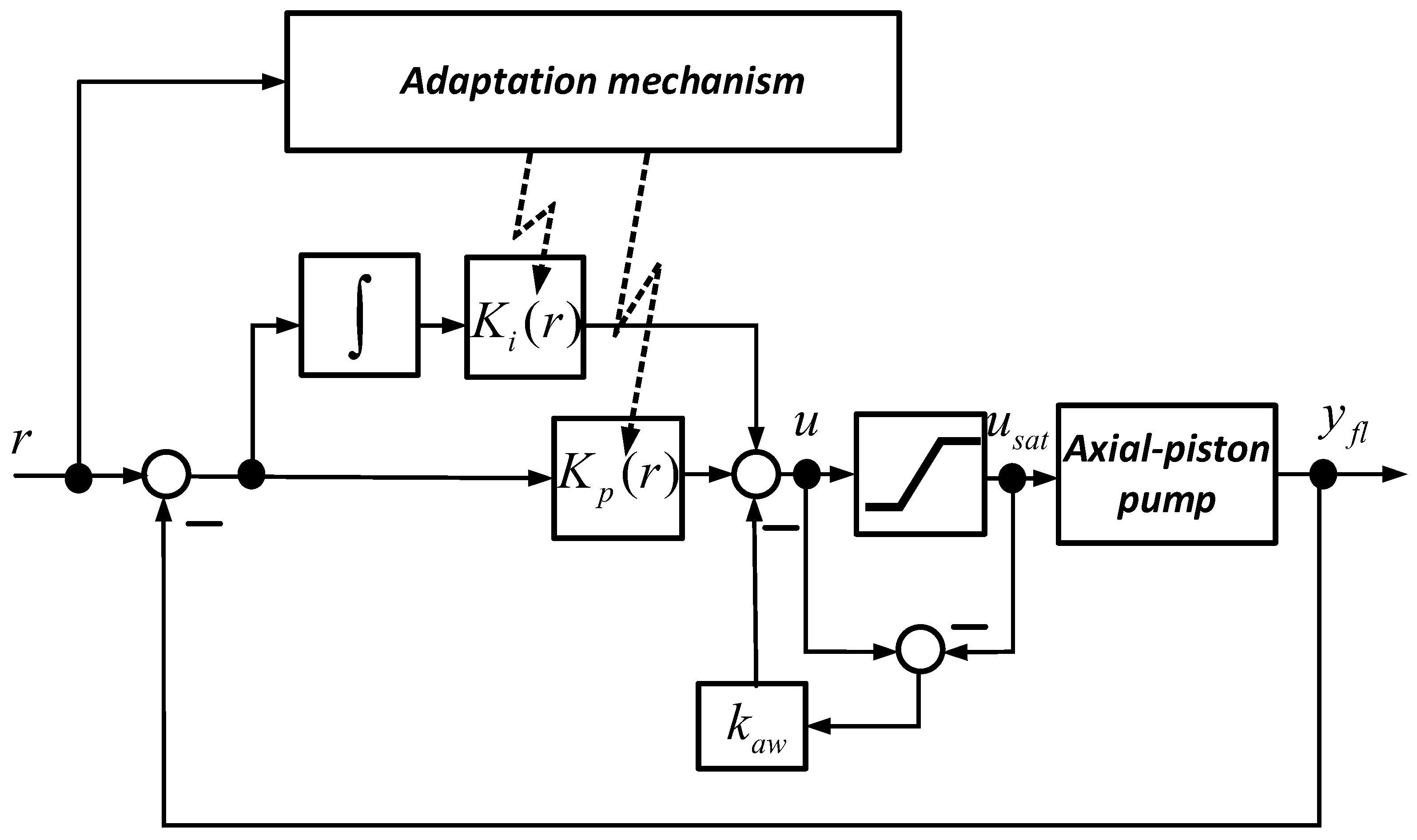
The expression (2) and transfer function (1) form the linear parameter-varying model of the axial piston pump that is used for gain scheduling PI controller design. The adaptive gain scheduling controller is described by the following equation:
where
is the control signal;
is the reference error;
is the axial piston pump flow rate; and
is either the control signal upper bound or control signal lower bound and is evaluated as follows:
The controller proportional gain
and controller integral gain
are tuned online with respect of the current value of reference, which are dependent on the current value of loading.
is an anti-wind-up gain that is chosen experimentally to achieve proper wind-up compensation. In order to provide sufficiently fast dynamics of the control system and the desired type of transient response, the expressions for tuning of adaptive controller parameters are derived from the condition for desired closed-loop system poles placement. The transfer function of closed-loop system is as follows:
On the basis of various experiments, the desired characteristic polynomial is chosen as follows:
This choice of desired characteristic polynomial provides a transient response with the settling time up to 150 ms with sufficiently small overshoot. After equating the denominator of the transfer function (5) and the desired polynomial (6), the following expressions for controller parameters and real-time tuning are obtained:
After taking into account expression (2) and the value of the plant time constant, one obtains the following:
Equation (8) is used for real-time tuning of adaptive controller parameters. The scheme of the closed-loop control system is presented in
Figure 6.
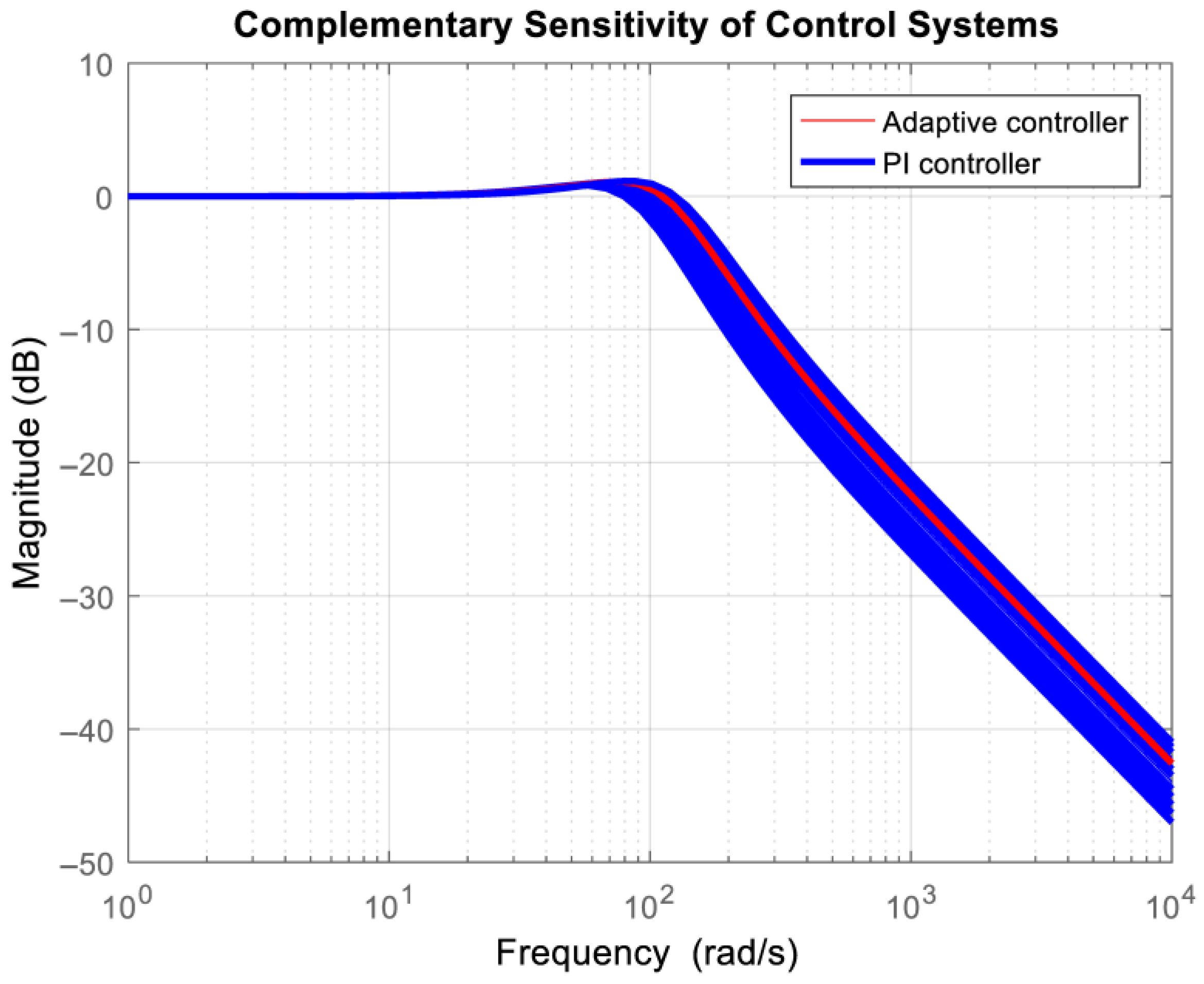
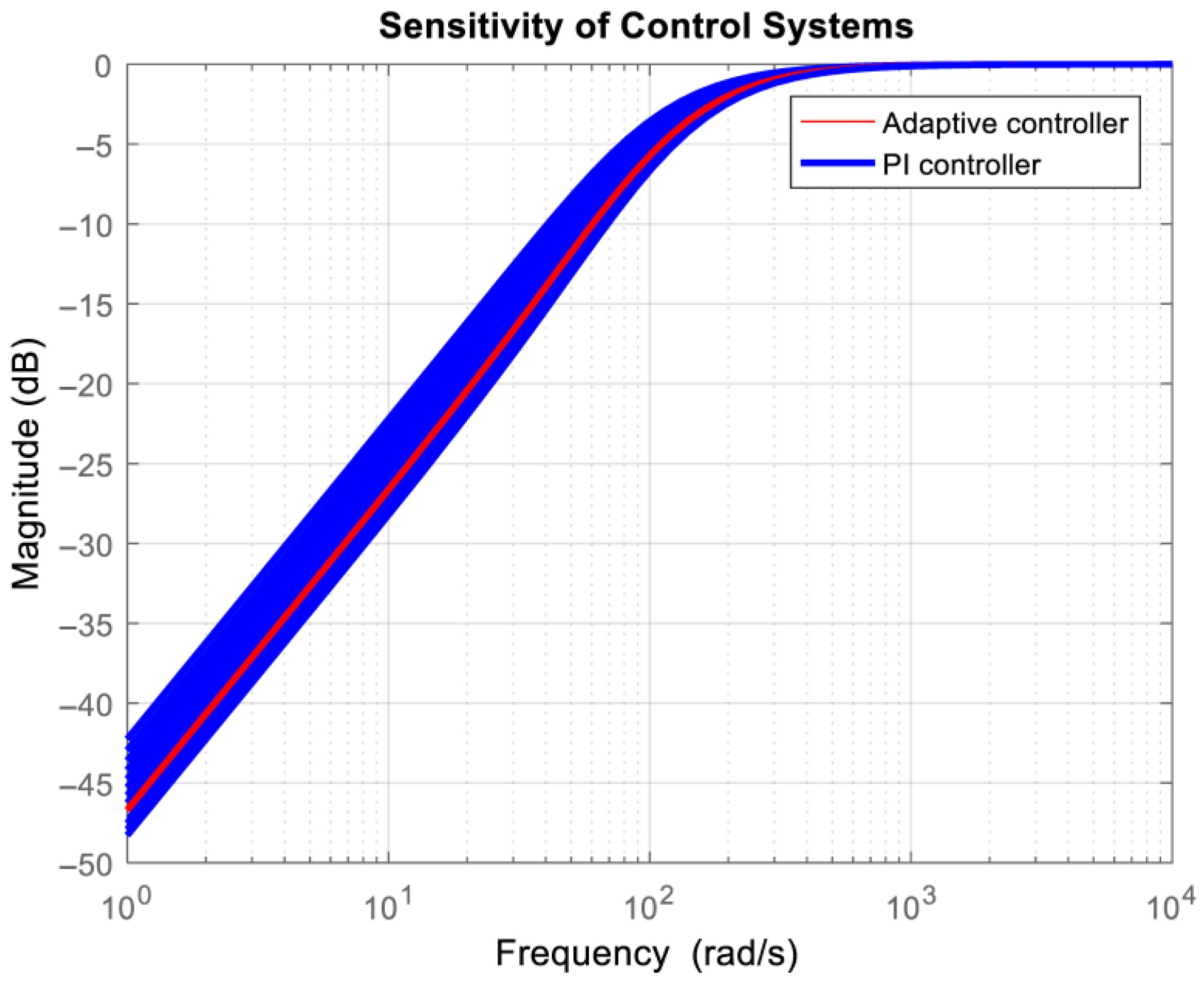
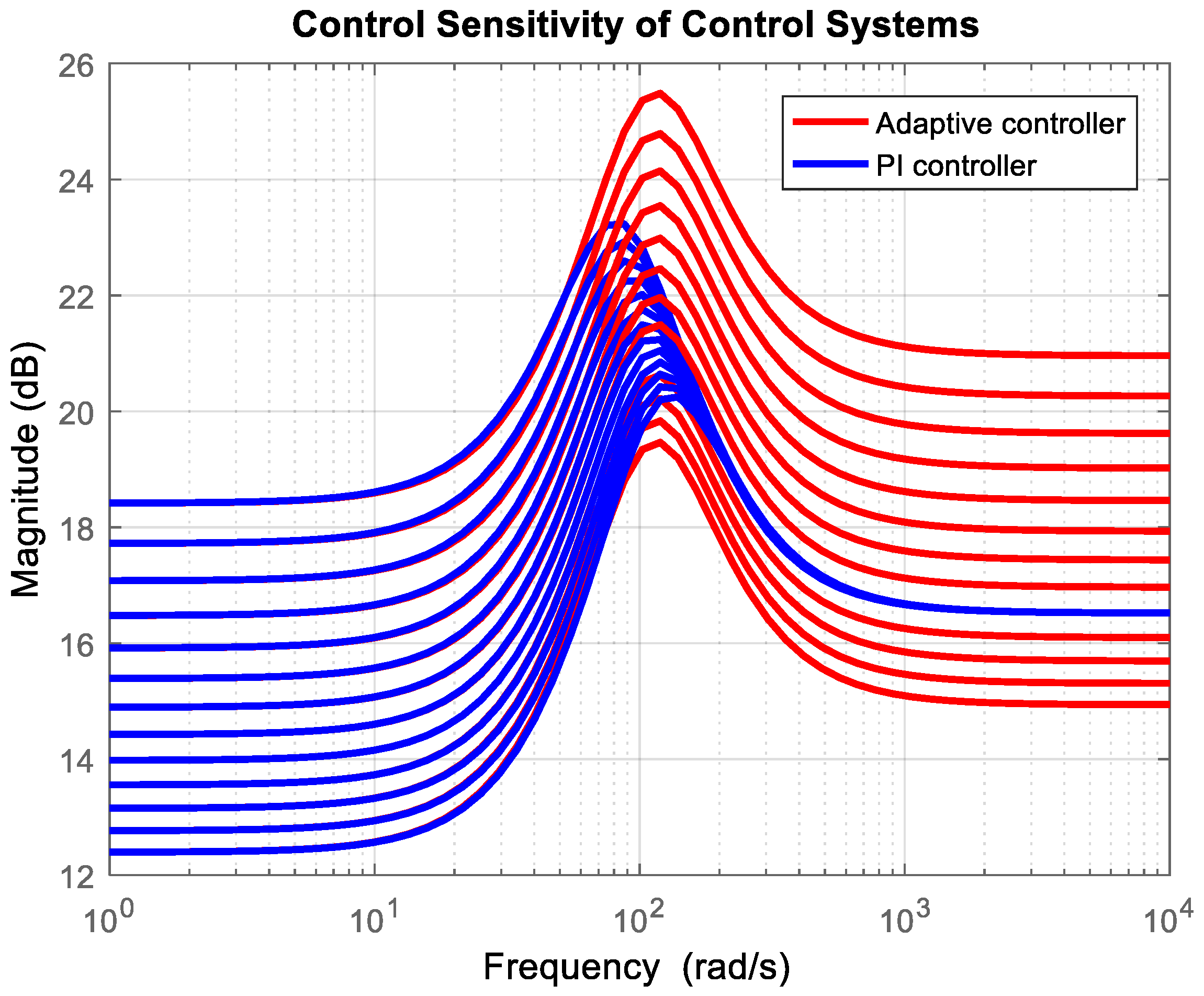
For comparison purposes, a conventional PI controller is designed for the plant model with a gain corresponding to the desired flow rate of 20 L/min. In
Figure 7,
Figure 8 and
Figure 9, the sensitivity functions of the adaptive control system and the control system with PI controller are presented. They are evaluated for the reference signal from 12 L/min to 24 L/min.
It is seen that the bandwidth of the adaptive control system is almost the same for the whole working mode of the axial piston pump, and it is approximately 100 rad/s. Thus, the transient response settling time will be approximately 100 ms. This shows the insensitivity of the adaptive control system to variations in the plant model (variations in loading). The control system with a conventional PI controller has various bandwidths with respect to the current values of loading and reference signal. It varies between 80 rad/s and 150 rad/s. Both control systems will suppress low-frequency loadings sufficiently well. However, the adaptive control system has different sensitivities of the control signal for various loadings in the high-frequency range. This will lead to an increase in measurement noise for some loadings. This is because the adaptive controller aims to compensate for variations in plant gain.
4. Experimental Study
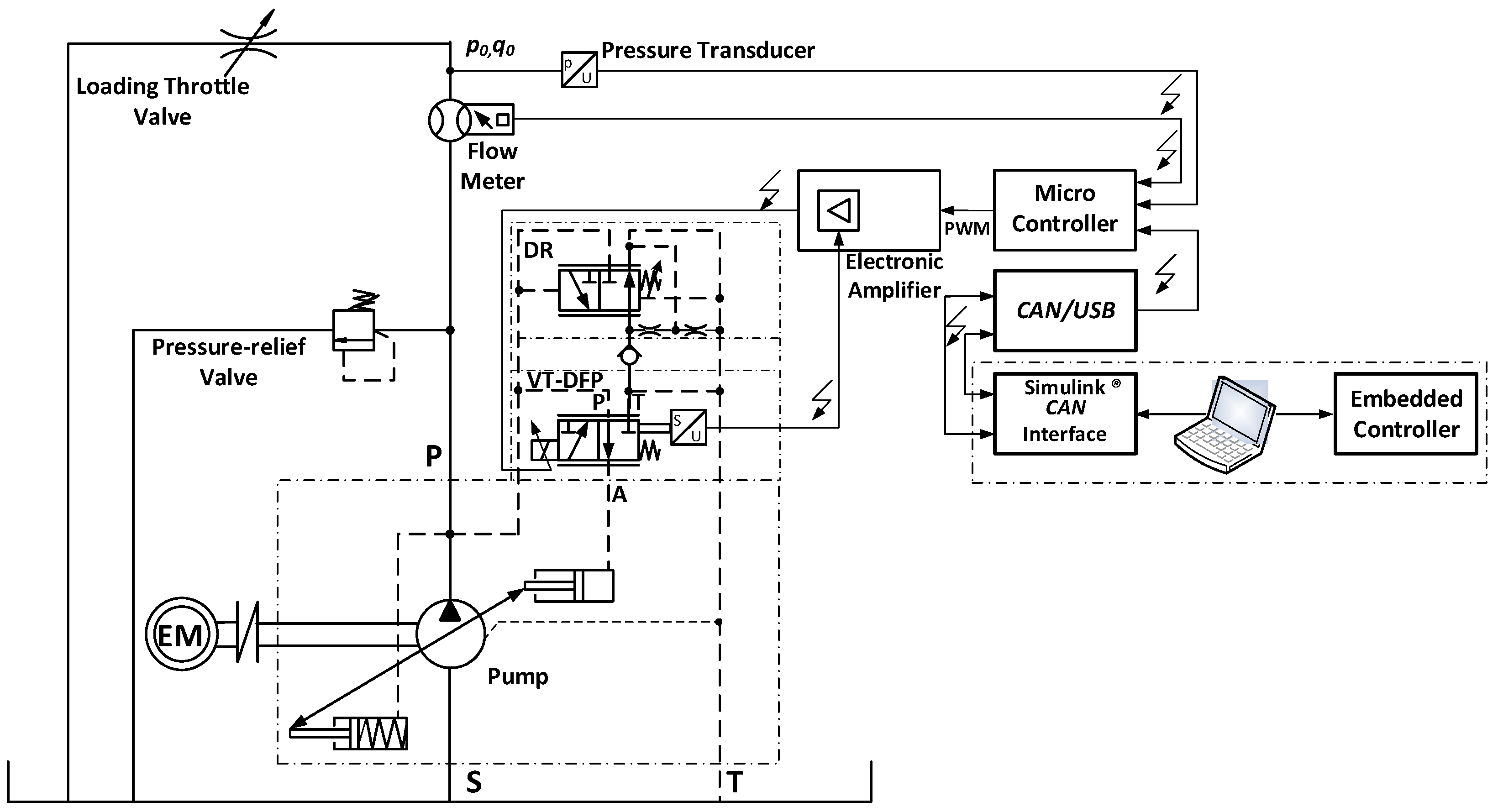
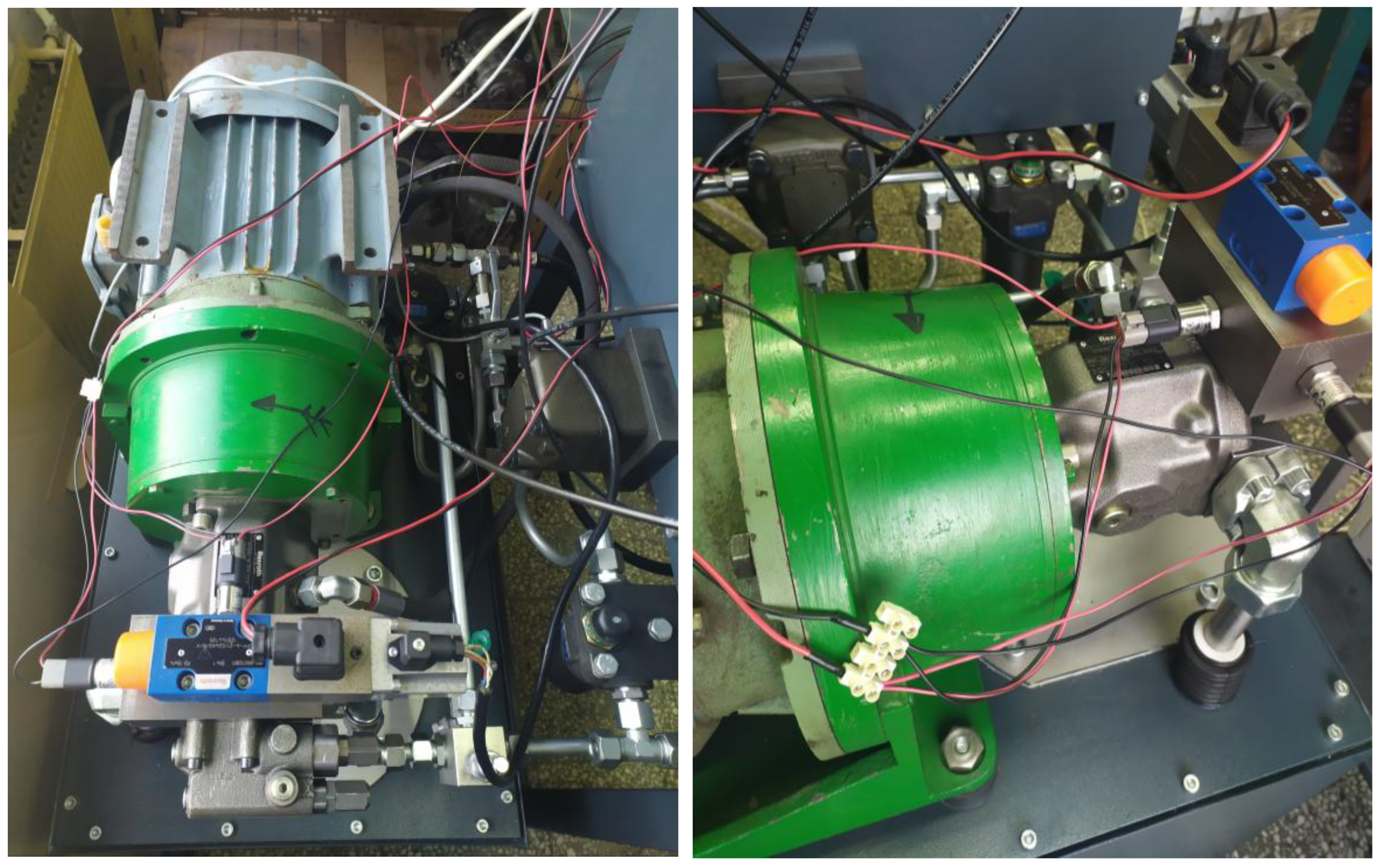
The experimental setting involves using a Danfoss®® MC012-022 microcontroller as a hardware interface to a pressure and flow control system, which regulates a proportional spool valve (through VT 5041-3X (Bosch Rexroth, Schwieberdingen, Germany) external amplifier) to control the swivel angle of an axial piston pump. The controller logic is implemented as a Simulink®® model, which is executed in real-time and communicates with the MC012-022 via a CAN bus using a Kvaser® transceiver. The flow output of the pump is directly proportional to the swash plate’s swivel angle, which is actuated by a hydraulic piston controlled by the proportional spool valve.
The MC012-022 is programmed to receive CAN messages from the host PC (Simulink®®) and to output corresponding PWM signals. The MC012-022 also manages the timing and synchronization required for real-time control, ensuring that the control loop operates at the specified sample time. Feedback signals, including flow rate from a flow meter or pressure from a transducer, are routed back to the Simulink®® model via the MC012-022 and CAN interface, closing the control loop.
The experimental data recorded in this study consist primarily of transient and steady-state measurements of pump flow rate, output pressure, and control signals under a variety of operating conditions and load scenarios. Different load levels are achieved by adjusting a manually operated hydraulic throttle check valve and a range of flow rate setpoints. The different pressure load modes correspond to the different settings of the internal throttling area of the valve, which is set before each experiment. The smallest load corresponds to the largest throttling area (loading 5), and vice versa, the largest pump load is at the smallest throttling area (loading 2). The repeatability of the settings is ensured by the millimeter scale on the throttle adjustment screw, with the possibility of fixation. For each load, the system was subjected to step input changes, and the resulting flow rate responses, control signals, and output pressures were measured. The recorded data captures the dynamic behavior of the pump across its practical working range, reflecting how the controller adapts to changes in load and setpoint, and thus provides a basis for validating both the control strategy and the underlying LPV model used for controller design. The data illustrate the impact of adaptive gain scheduling compared to classical PI control and the classical LQR controller. It should be noted that the LQR controller is designed by the authors based on the identified multivariable black box axial piston pump model of 6th order [
46]. The LQR controller is of 7th order due to the extension with integral state, and it is significantly more complex than the adaptive PI controller.
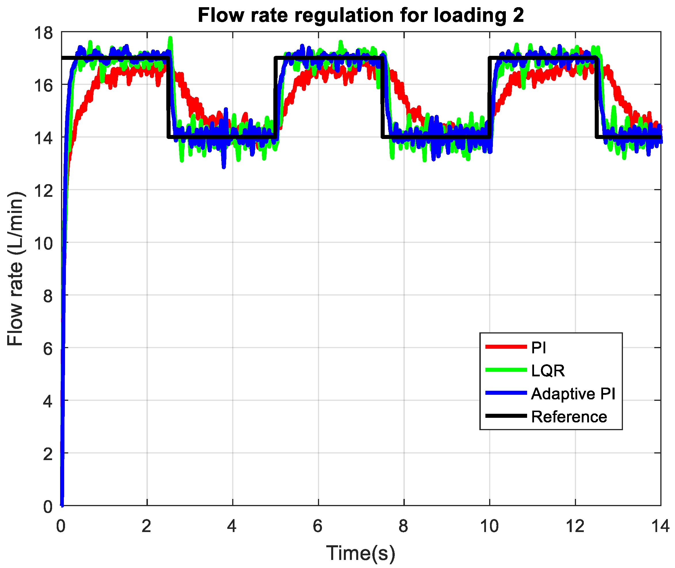
Figure 10 illustrates the flow rate regulation performance of the axial piston pump under the highest loading condition (2 mm opening of the throttle valve), comparing a classical PI controller (red), LQR controller (green), and an adaptive PI controller (blue) against the reference step signal (black). The adaptive PI controller demonstrates a notably faster transient response, achieving a shorter settling time (about 100 ms) after each consecutive step change in the reference compared to the classical PI controller (1 s settling time). Additionally, the adaptive PI consistently tracks the reference with minimal steady-state error, closely following the setpoint during both high and low flow demands. In contrast, the classical PI controller exhibits a slower rise time and a larger steady-state error (about 0.8 L/min), particularly evident after upward steps, where it fails to reach the reference level as accurately as the adaptive PI. The settling time for the LQR controller is comparable to the adaptive PI controller (around 100 ms) but exhibits slightly more oscillations in the flow rate than the LQR controller, particularly during transients following sudden load changes.
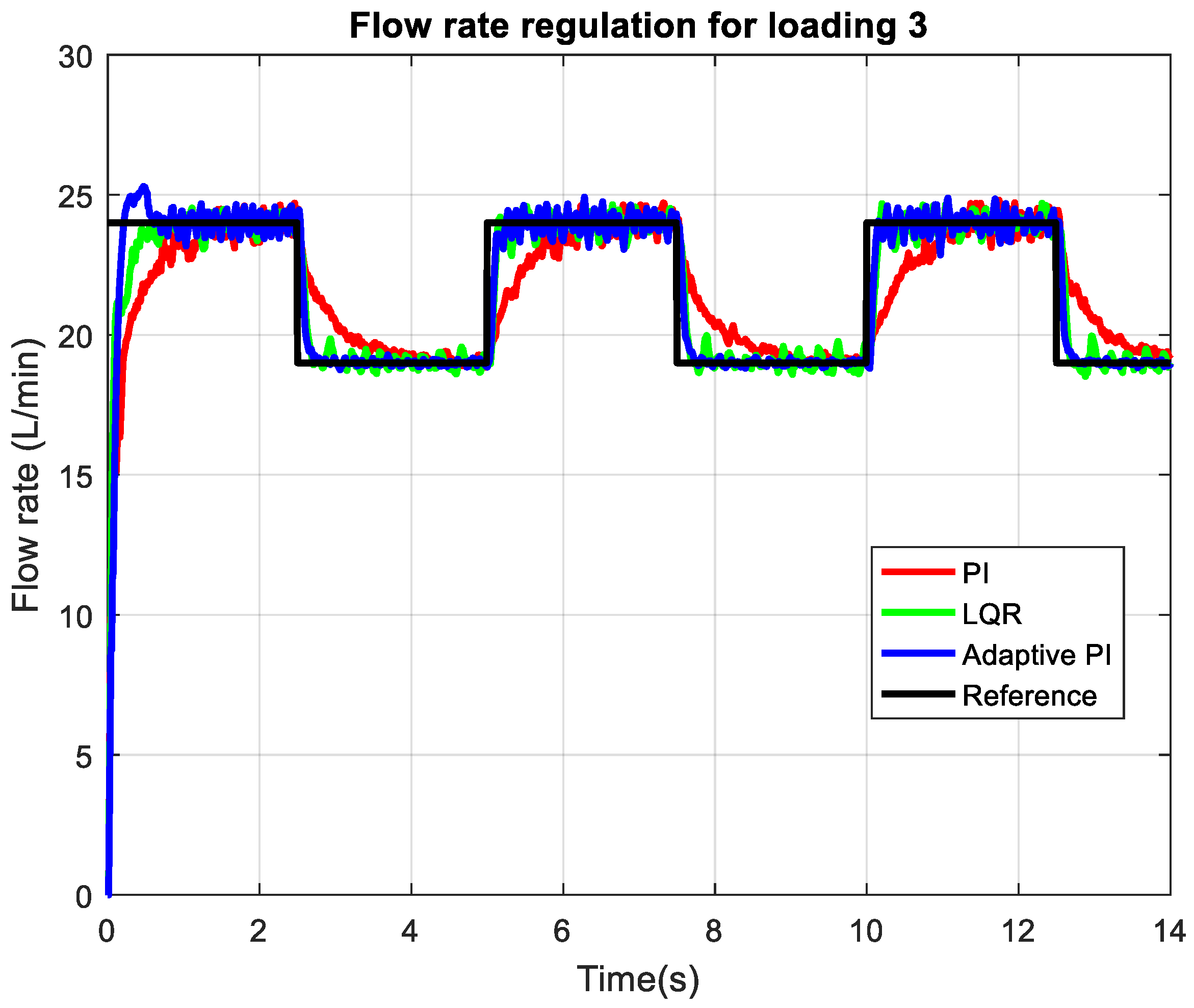
Figure 11 shows the flow rate regulation performance of the axial piston pump at 3 mm throttle valve opening, which represents a lower loading than the previous loading 2 case. At this reduced load, three controllers exhibit improved transient characteristics compared to higher loading: the settling times are shorter, and the steady-state errors are smaller for three controllers. The adaptive PI controller continues to outperform the classical PI by achieving faster rise times and more precise tracking of the reference during both step increases and decreases in flow rate. The classical PI, while improved over its performance at higher loading, still shows a slightly slower response. The LQR controller again produces more oscillations in flow rate compared to the adaptive PI controller, especially for a reference of 14 L/min. The LQR controller, however, responds with no overshoot to the initial flow rate command.
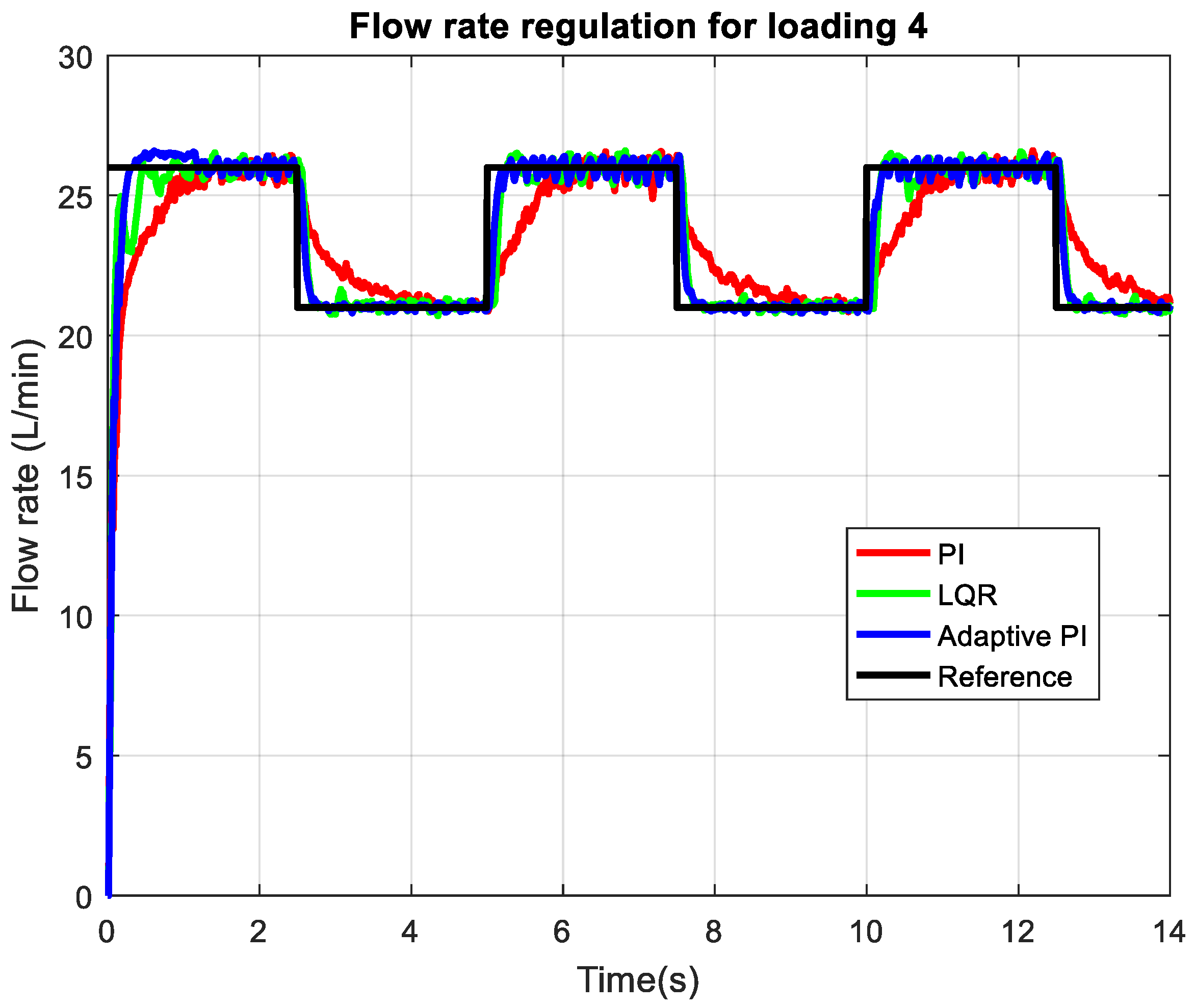
At loading 4 (
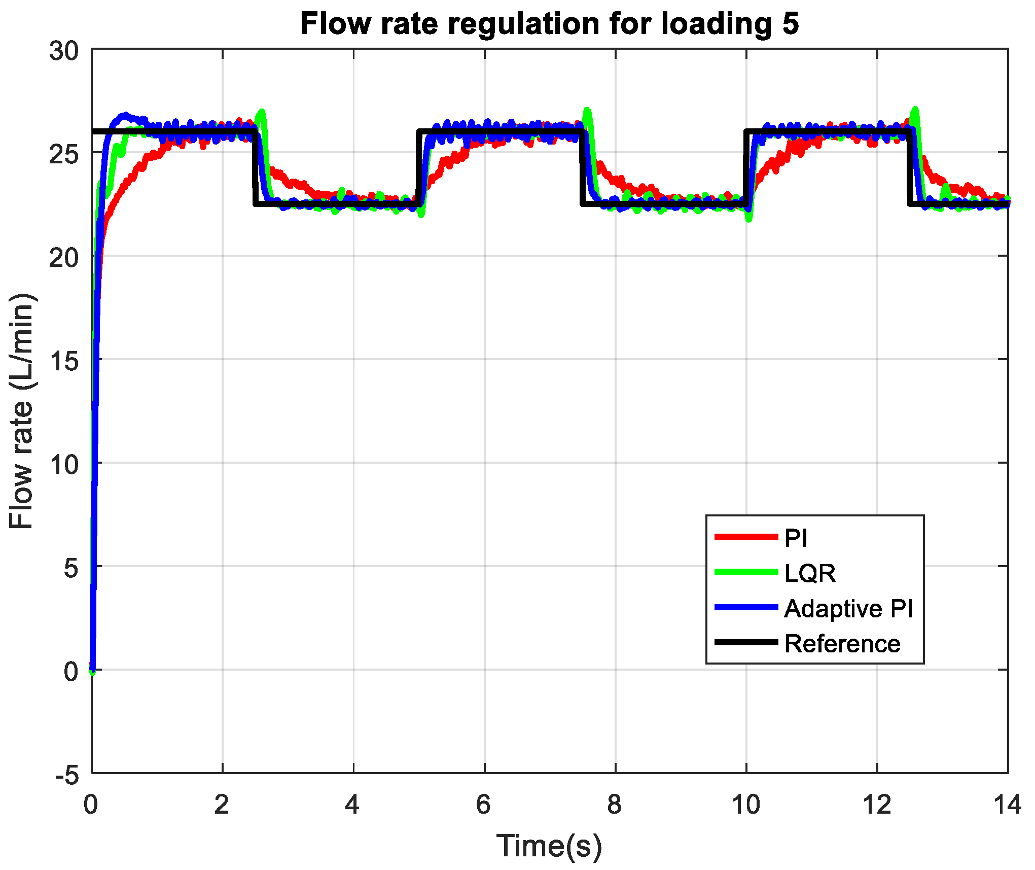
Figure 12), corresponding to a 4 mm throttle valve opening and thus the lower loading condition considered, the flow rate regulation performance further improves for three controllers. The figure shows that both the LQR controller (green) and the adaptive PI controller (blue) achieve very rapid responses to step changes in the reference (black). The adaptive PI controller continues to provide a faster response than the classical PI controller and tracks the reference almost perfectly, exhibiting negligible steady-state error and minimal overshoot or undershoot throughout all transients. During the initial step the LQR controller response is slower than adaptive PI. For the following steps both controller tracking is overlapped with slightly more deviations observed with the LQR controller for the reference level of 21 L/min. At the lowest loading condition, corresponding to a 5 mm throttle valve opening,
Figure 13 demonstrates that three controllers keep their behavior consistent with previous observations for loadings 3–4. The adaptive system responds almost instantaneously to step changes in the reference (smaller than 100 ms settling time) and steady-state oscillations smaller than 0.2 L/min. The classical PI controller still lags behind the adaptive PI in response time. The LQR controller consistently reacts in the opposite direction during the transition from 26 L/min to 22.5 L/min command. This is attributed to the discrepancies between the model used for the LQR design and the actual dynamics. The adaptive controller can prevent such behavior since its parameters are updated to match the plant dynamics.
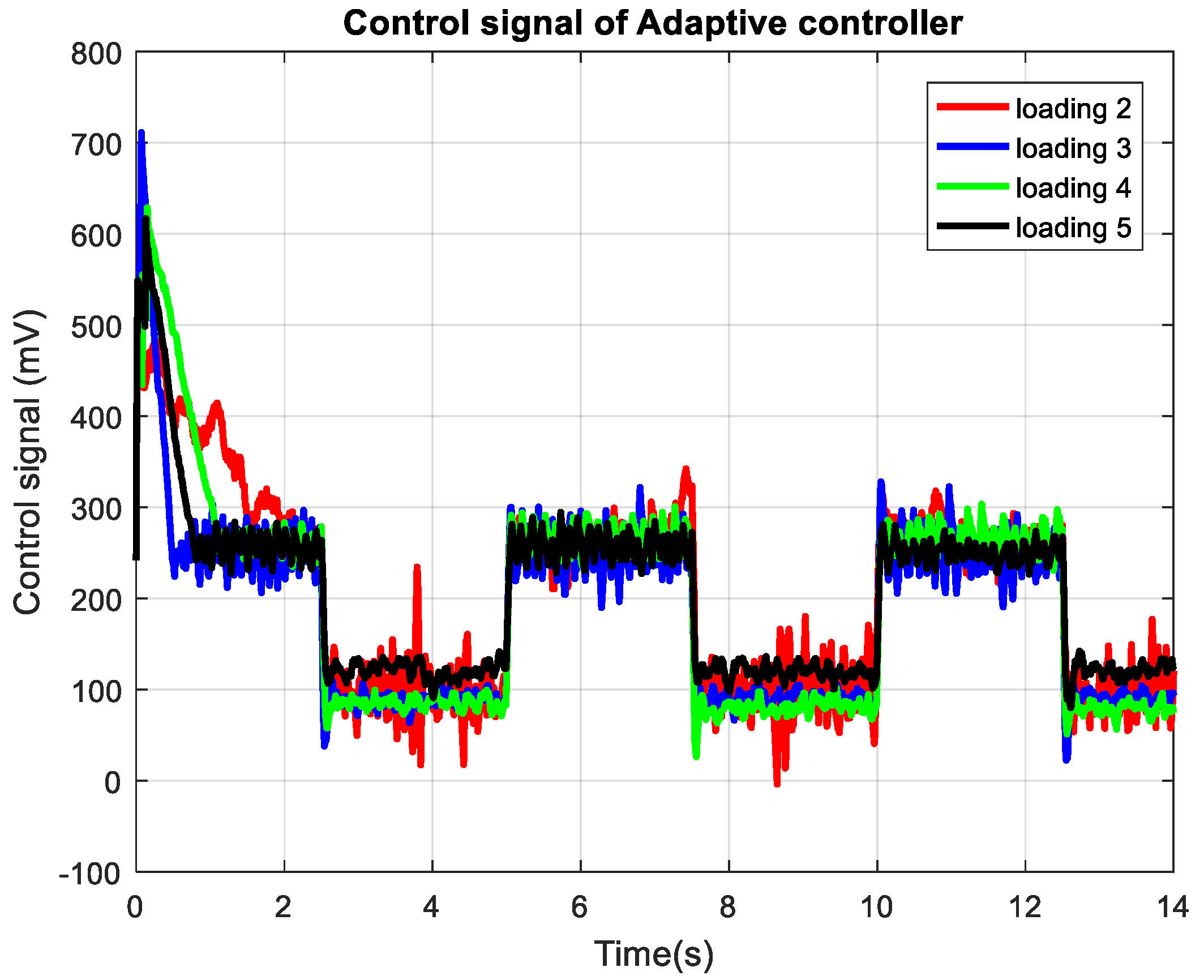
Figure 14 displays the control signals generated by the adaptive controller for four different loading conditions, as indicated by the throttle valve openings. At the highest loading (loading 2), the controller issues the most dynamic control actions, particularly evident in the higher amplitude oscillations following step changes, reflecting the increased effort required to overcome greater hydraulic resistance and achieve rapid reference tracking. As the loading decreases (from loading 3 to loading 5), the control signals become progressively smoother and less aggressive, with lower peak values and reduced variability, indicating that less actuation is needed for the system to follow the reference accurately. This pattern directly correlates with the reference tracking results, demonstrating the adaptive controller’s ability to modulate its output across a wide range of operating conditions.
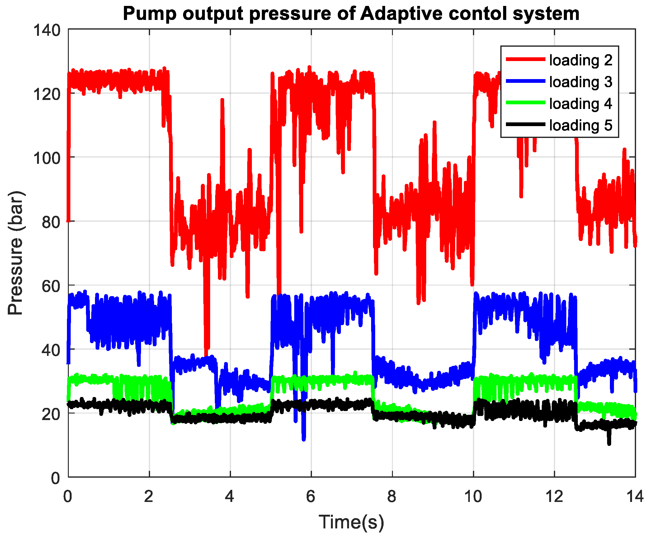
Figure 15 shows the pump output pressure for the adaptive control system under four different loading conditions. As the loading increases, the pump is required to generate significantly higher pressures to maintain the same target flow rate, resulting in the highest and most variable pressure profiles for loading 2, where output pressures frequently reach as high as 120 bar and exhibit pronounced fluctuations during transients. In contrast, at lower loadings (loadings 4 and 5), the required pump pressure drops substantially, with the lowest loading showing pressures below 30 bar and much smoother profiles. This inverse relationship between loading and output pressure directly reflects the hydraulic system’s behavior. The achieved flow rate remains well-regulated across all conditions due to the adaptive controller, but the energy demand and mechanical stress on the pump are much greater at high loading, as evidenced by the elevated and more oscillatory pressure.
Figure 16 presents the proportional spool valve feedback signal for the adaptive control system across four loading conditions, illustrating how the valve position (in mV) changes in response to step changes in flow demand. In this system, the proportional valve directly actuates the swash plate driving piston, which in turn sets the swivel angle of the swash plate in the axial piston pump, thereby controlling the pump’s displacement and output flow. The observed control signals reveal that under higher loading (loading 2), the valve must open periodically wider and respond with greater fluctuations to generate sufficient hydraulic force to move the swash plate against increased resistance and friction. As the loading decreases (loadings 3–5), the required valve openings are lowered and the signals become smoother, indicating that less force is needed to reposition the swash plate and achieve the desired flow. This behavior reflects the nature of this pump model where the proportional valve modulates pressure to the actuator piston, which must overcome not only the load but also internal friction, spring forces, and oscillatory torques from the pump’s rotating group.
For comparison purposes, the integral square error (ISE) of the axial piston pump control system is introduced as follows:
Table 1 presents values of index (9) for the adaptive control system, the LQR control system, and the classical PI control system across four loading conditions. The ISE index is evaluated for
and
according to the results in
Figure 10,
Figure 11,
Figure 12 and
Figure 13. In every case, the adaptive control system consistently achieves a lower ISE than the PI controller, indicating superior tracking accuracy and overall control performance. The difference is pronounced for both the higher loading and the lower loading: for example, at loading 3, the adaptive controller’s ISE (1431.2) is substantially lower than that of the PI controller (2620.4), and at loading 2, the adaptive system also outperforms the PI controller by a significant margin (1114 vs. 1668.1). The values for ISE index of adaptive controller system is smaller than the one for the LQR control system except for the case of loading 3. This is because the axial piston pump model that was used for the LQR controller design is identified from the conditions of loading 3. As loading decreases (from loading 2 to loading 5), the ISE values for the three controllers decrease, reflecting easier control at lower loads. However, the adaptive controller maintains a clear advantage at all loadings, with its ISE dropping to 998.4 at the lowest load (loading 5), compared to 2032.8 for the PI controller and 1072.5 for the LQR controller.
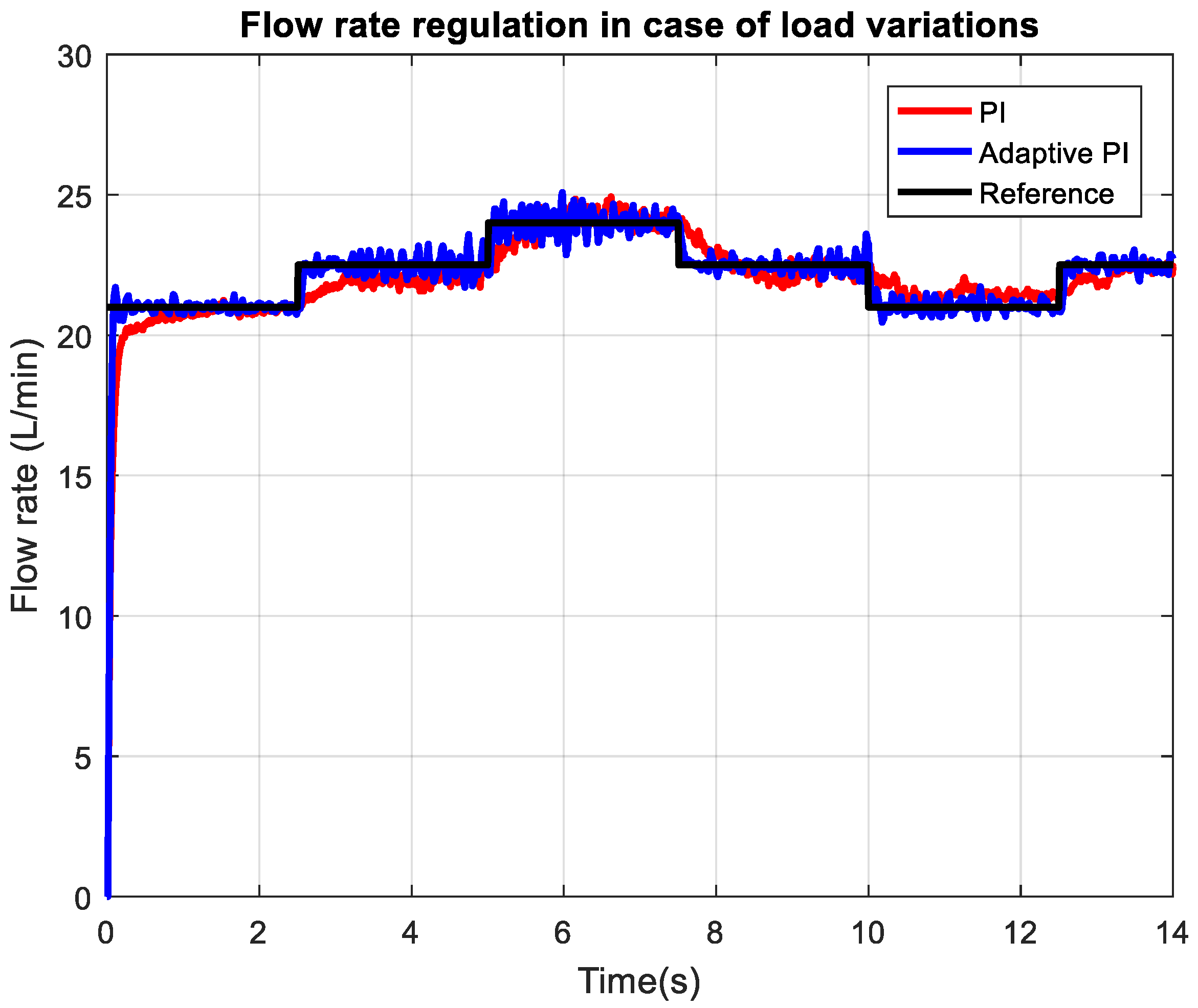
Figure 17 presents the measured flow rate of the axial piston pump under dynamically changing load conditions, illustrating the real-time performance of the control system. The plot showcases how the controller reacts to rapid and significant variations in hydraulic loading, with multiple step changes appearing throughout the time interval tested. Despite these dynamic disturbances, the flow rate remains tightly regulated and follows the reference trajectory with minimal delay, undershoot, or overshoot.
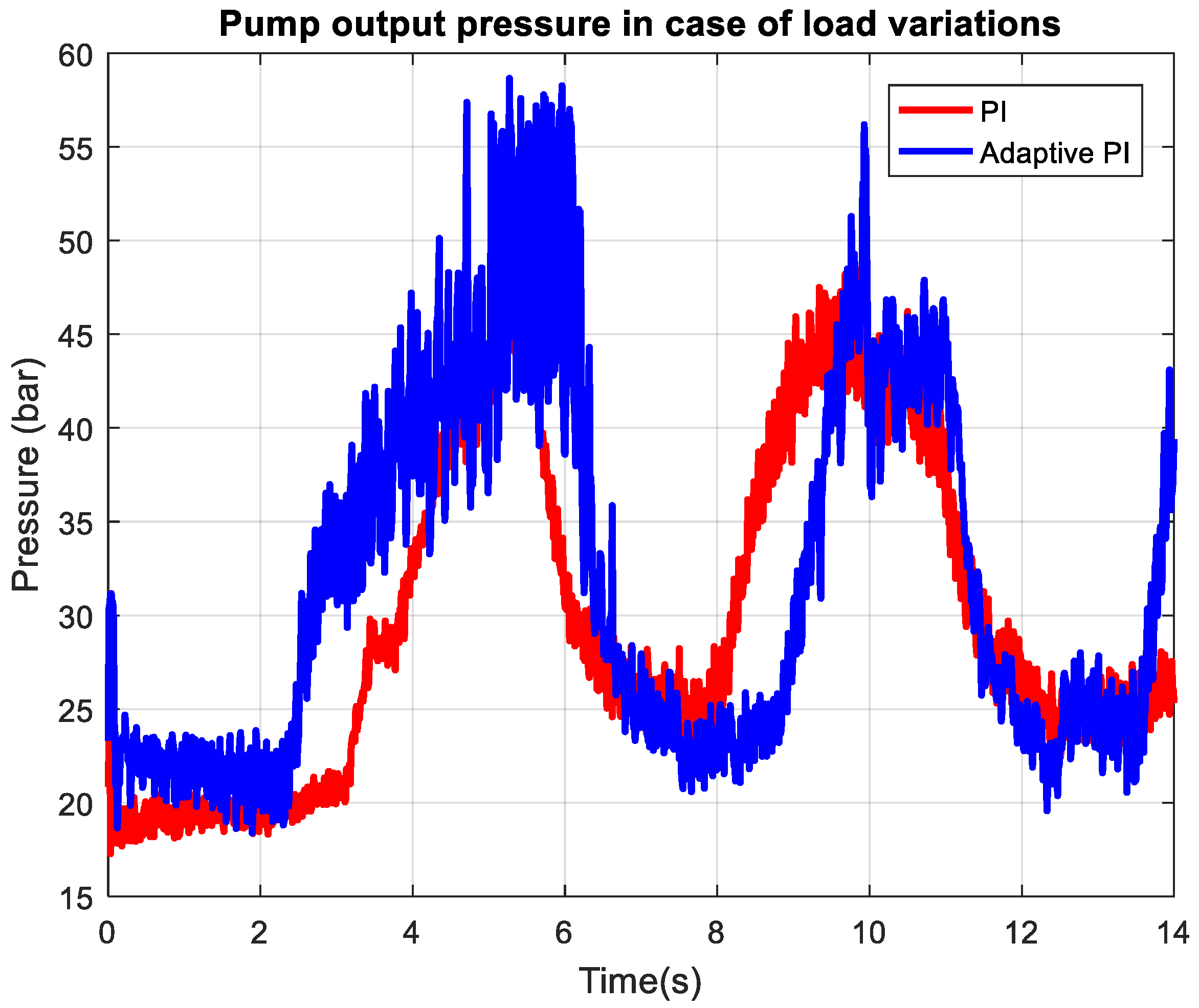
Figure 18 depicts the axial-piston pump output pressure response under conditions of dynamically changing load, providing real-time insight into how the control system copes with rapid and substantial load fluctuations. Throughout the sequence of load changes, the pressure signal exhibits marked transient spikes and troughs that directly correspond to each disturbance,
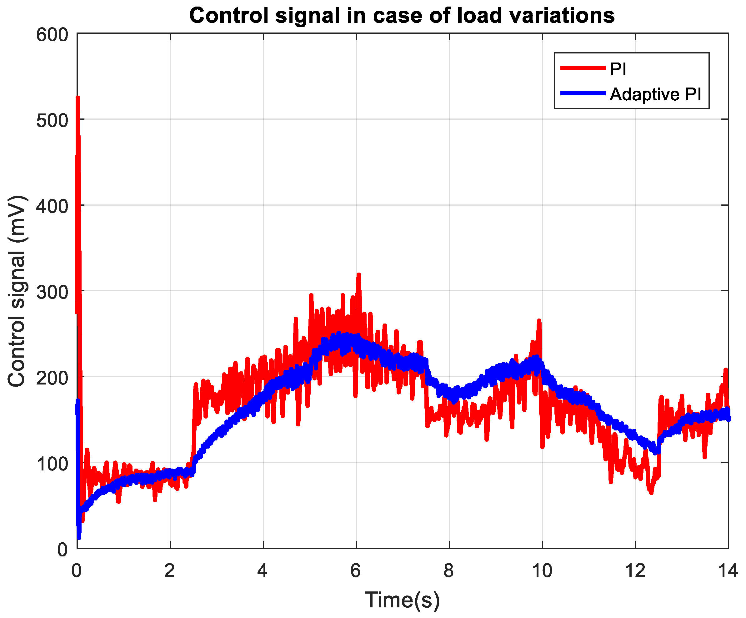
Figure 19 displays the control signal behavior of the adaptive PI controller in response to dynamically varying load conditions. Throughout the experiment, the control output adapts rapidly to each step change in pump load, producing pronounced spikes and adjustments that enable the system to maintain desired flow and pressure levels. The waveform of the control signal for adaptive PI is smoother which is attributed to better compensation of the plant dynamics.
5. Conclusions
This study demonstrates that implementing a real-time gain-scheduling PI controller based on a linear parameter-varying model significantly enhances the performance of displacement volume regulation in swash plate-type axial piston pumps. By replacing the traditional hydro-mechanical controller with an electronically controlled proportional spool valve, the system enables more flexible and precise control over the pump’s output. The adaptive controller dynamically adjusts its parameters in response to changes in operating conditions—specifically, variations in load and flow rate setpoints—using a model whose static gain is directly linked to the current flow rate reference. This approach addresses the limitations of fixed-gain PI controllers, which struggle to maintain optimal performance across a wide range of hydraulic loads and dynamic scenarios.
Experimental results obtained through rapid prototyping and real-time testing confirm that the adaptive PI controller consistently outperforms the classic PI controller across all evaluated loading conditions. Under high loading, the adaptive controller achieves faster settling times, reduced steady-state errors, and more robust tracking of reference signals, even as the system faces increased hydraulic resistance and dynamic disturbances. As the load decreases, both controllers benefit from improved plant responsiveness, but the adaptive controller retains a clear advantage in tracking accuracy and transient response. The integral square error (ISE) metrics further validate these findings, with the adaptive controller showing significantly lower ISE values at every load, highlighting its superior ability to minimize tracking error and maintain stable operation.
This study also underscores the importance of the proportional valve’s role in the control architecture. The valve acts directly on the swash plate driving piston, modulating hydraulic force to adjust the swash plate angle and, consequently, the pump’s displacement volume and flow direction. The adaptive controller efficiently manages the valve actuation effort, issuing more dynamic and higher-amplitude control signals under heavy loads to overcome increased resistance, while producing smoother, less aggressive commands as the system load lightens. This adaptability not only ensures precise flow regulation but also optimizes energy use and reduces mechanical stress on the pump components.
The obtained results show the applicability of the adaptive control approach based on the 1st order LPV model for axial piston pump control. This motivates future work to design other adaptive controllers based on the developed model, such as model reference adaptive controllers (MRACs).
