Abstract
Aircraft encounter complex ground and air scenarios during service, necessitating a comprehensive analysis of extensive global load cases during the design phase to ensure structural reliability and safety. While high-fidelity finite element analysis enables precise assessment of load case criticality, its prohibitive human and computational costs constrain aircraft iterative development. To overcome this challenge, this study proposes a Global Load Case Analysis (GLCA) system for identifying critical load cases across structural sections. The method is driven by aerodynamic load data and structural response data from coarse-grid models. First, it achieves a quantitative ranking of global load case criticality, providing engineers with a standardized severity metric. Second, based on defined criticality relationships, it identifies coverage, coupling, and differentiation patterns among load cases to establish criticality hierarchies. Finally, a novel 1DCNN architecture with specialized training strategies learns the GLCA system’s behavioral patterns, enabling accurate prediction of criticality for newly added load cases without computationally intensive reanalysis. The results demonstrate strong agreement between GLCA and high-fidelity model analyses: quantitative ranking achieves 95.98% average accuracy with complete identification of critical load cases. Predictions for new load cases yield coefficients of determination (R2) > 0.98 and 97.91% average criticality classification accuracy. Furthermore, GLCA operates 335 times more efficiently than high-fidelity finite element analysis. This approach effectively substitutes high-fidelity modeling during load development, reducing human effort and shortening aircraft design iteration cycles.
1. Introduction
During the preliminary and early detailed design phases of military and commercial aircraft, a wide range of maneuvers—including roll maneuvers (Roll Maneuver, Roll Recovery), pitch maneuvers (Stall Recovery, Zoom Climb Turn), yaw maneuvers, and combined maneuvers—must be considered as they generate complex load cases. The complex ground and air scenarios encountered pose significant challenges to structural reliability and safety [1,2]. Comprehensive analysis of overall load cases is critical for evaluating aircraft structural safety across diverse scenarios and serves as a fundamental basis for structural optimization design [3]. Analysis methods based on high-fidelity finite element modeling provide accurate and detailed global structural health assessments, enabling the precise identification of critical load cases. However, this approach heavily relies on extensive manual effort for model construction and is constrained by prohibitive computational resource requirements and time consumption, making it impractical to analyze the entirety of all global load cases [4,5]. Consequently, the inefficiency in identifying critical load cases under global conditions has become an essential bottleneck constraining structural design and technological iteration [6].
Traditional critical load selection methods encompass Design Point, Parametric Analysis, and Load Envelope methods. These approaches are widely adopted in engineering practice and generally accomplish the task from preliminary to refined screening of load cases [7]. However, they exhibit a high dependency on engineering expertise, requiring manual analysis of extensive datasets and graphical comparisons. When introducing new load cases, all data and plots require updating, followed by re-analysis, which incurs substantial time and labor costs. To mitigate this reliance on subjectivity and reduce human resource consumption, numerical computation-based methodologies have emerged. Dharmasaroja.A [3] focused on aircraft structural components, applying Singular Value Decomposition (SVD) for feature load extraction and reconstruction to reduce the number of cases requiring evaluation. The same research group further established a feature load space, constructed an envelope surface for structural failure, and identified critical load cases by calculating Reserve Factors (RF) [8,9]. However, this method is only applicable to component-level analysis and is difficult to extend to full-aircraft global analysis. Furthermore, significant computational resource consumption persists during the construction of the load space envelope surface. R.Nazzeri [6] innovatively introduced Artificial Neural Networks (ANN) into this domain, utilizing structural component physical properties to predict RF values. Nevertheless, this approach remains confined to component-level analysis and fails to achieve comprehensive evaluation at the full-aircraft level.
This paper presents an innovative Global Load Case Analysis (GLCA) method, a novel methodology for critical load identification and prediction. The method utilizes aircraft structural cross-sections as fundamental analysis units to achieve four objectives: identification of critical load cases, quantification of hazard levels across full-aircraft global load cases, risk-level classification, and efficient hazard prediction for newly introduced load cases. Three interconnected core methodologies constitute the GLCA framework: (1) Multidimensional Sliding-Window Fusion-based Risk Quantification and Rank (MWRQ) jointly analyzes aerodynamic loads and structural responses at aircraft cross-sections. A sliding-window segmentation algorithm selectively fuses results from three distinct analytical approaches: a physics-informed high-dimensional envelope method, a numerical solution evaluation technique, and a statistics-based structural response assessment. This fusion enables precise hazard quantification of load cases. (2) Integrated Multi-step Refinement Methodology for Criticality Classification of Load Cases (IMRC) implements a specialized clustering framework for aerodynamic load data. A dual-layer clustering architecture is constructed, with multiple clustering algorithms deployed intra-layer for boundary identification. Harris Hawks Optimization (HHO) [10] is applied inter-layer to locally tune intra-layer hyperparameters and fusion weights. Global parameter optimization is subsequently performed using Non-dominated Sorting Genetic Algorithm III with Expected Hypervolume Improvement (NSGAIII-EHVI) [11,12,13], collectively accomplishing risk classification and critical load case identification. (3) Multi-Slice 1DCNN Feature Extraction Fusion for Hazard Prediction (MS-1DCNN) employs SMOTE-KTLNN [14] to resolve extreme data imbalance while augmenting operational scenarios; raw aerodynamic load data are then segmented into multiple slices. Dedicated feature extraction networks process each slice, while a backbone network fuses extracted features to facilitate rapid hazard prediction for new load cases.
In practical applications, the MWRQ method serves as the initial processing module within the data stream, performing the primary assessment of load case criticality. This method is applicable during the initial aircraft design phase, providing engineers with guidance for identifying high-risk load cases during local structural design iterations to clarify structural design direction. Subsequently, the IMRC method utilizes the MWRQ analysis results to execute critical load case screening and assess the severity ranking of load patterns. It operates during the critical transition phase from initial to detailed design. This process enables engineers to efficiently identify and select critical load cases, providing a basis for the subsequent rapid iterative optimization of structural layout and aerodynamic shape. Finally, the MS-1DCNN module integrates the analytical outcomes from both MWRQ and IMRC to train an aircraft-type-specific prediction model. This model enables rapid determination of the criticality of subsequently added load cases and pinpoints key load cases to guide further optimization efforts. The MS-1DCNN is primarily employed during the transition from the initial to detailed structural design phase to address the need for supplementary load cases arising from newly identified issues during the design iteration process [15,16,17]. Figure 1 illustrates the application points and functional roles of the GLCA methodology across various stages of aircraft design. Figure 1 illustrates the application points and functional roles of the GLCA methodology across various stages of aircraft design.
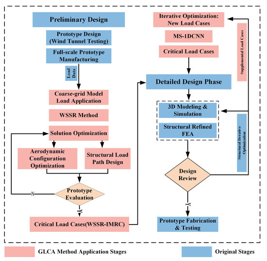
Figure 1.
Application scope and functions of the GLCA methodology scross aircraft design phases.
The effectiveness of the method was validated across different structural locations of the full aircraft. This validation encompassed the accuracy of MWRQ in quantifying and ranking the load cases, the coverage of IMRC in identifying critical load cases, and the accuracy of MS-1DCNN in predicting the criticality of newly introduced load cases. Building upon the demonstrated reliability of the GLCA method’s analysis results, its computational efficiency has been improved by three orders of magnitude compared to high-fidelity modeling.
In summary, our contributions are as follows:
- The MWRQ methodology is established to overcome limitations of conventional approaches, such as cumbersome manual operations and subjective dependencies. It achieves a global quantitative ranking of load cases for arbitrary structural cross-sections across the entire aircraft. This technique is applicable during preliminary design phases, providing engineers with guidance for identifying critical load conditions in local structural design stages, thereby clarifying structural design direction.
- The IMRC clustering algorithm is developed to execute critical load case selection and assess hazard levels of load patterns. It is specifically designed for the critical transition phase from initial concept to detailed design. This workflow enables engineers to efficiently identify and select key load cases, establishing a basis for rapid iterative optimization of subsequent structural layouts and aerodynamic profiles.
- The MS-1DCNN architecture integrates analytical outputs from MWRQ and IMRC to train an aircraft-specific prediction model. This model rapidly evaluates hazard levels for newly added load conditions and pinpoints critical cases to guide further optimization efforts. Its primary application resides in the transition from preliminary to detailed structural design, addressing scenarios requiring supplemental load conditions due to newly identified issues during design iterations.
- Validation against high-fidelity benchmark models demonstrates that the MWRQ method achieves over 94% ranking accuracy. The IMRC algorithm attains comprehensive identification of critical load cases with silhouette coefficients exceeding 0.7. For hazard-level prediction of novel load conditions, MS-1DCNN achieves R2 values exceeding 0.98 and classification accuracy surpassing 96.8%. System execution time for single cross-section analysis is 686.26 s.
2. Related Work
2.1. Development Status of Surrogate Models for Load Development Phase
Aircraft structural design comprises two core phases: load development and sizing. The load development phase focuses on assessing all potential load cases encountered throughout the aircraft’s service life. The sizing phase determines the final structural dimensions, meeting reliability requirements based on the load analysis results. These phases require multiple iterations, progressively refining the analysis from overall structural behavior down to detailed component design. Within the sizing phase, surrogate modeling is well-established for solving structural optimization problems [18,19]. This modeling technology, developed over time, finds application across diverse engineering scenarios [20], ranging from aero-engine turbine disks to composite bicycle frames [21]. Numerous effective surrogate models have also been developed specifically for aircraft semi-monocoque structures [22,23]. Conversely, surrogate model application within the load development phase remains notably underdeveloped. Current engineering practice commonly substitutes high-fidelity models with coarse-mesh models for load analysis. This approach suffers from two primary limitations: an inability to perform precise quantitative comparisons of criticality between different load cases, and the introduction of unavoidable analysis errors due to model simplification (mesh coarsening). These limitations compromise efficient iteration with subsequent structural optimization, prolonging the overall design cycle and ultimately constraining further improvements in aerospace structural performance [24,25,26].
However, the load case analysis method proposed in this study advances coarse-mesh modeling, bridging the surrogate model gap in load development. This approach enables engineers to precisely identify critical load cases and critical optimization regions without relying on high-fidelity models. It achieves equivalent results to high-fidelity analysis using only data collected from coarse-mesh models.
2.2. Overview of Current Critical Load Case Selection Methodologies
Aerospace structural design employs classical critical load case selection methods: Design Point, Parametric Analysis, Load Envelope, and MAST Envelope [7]. The Design Point method selects typical design loads based on engineering experience for preliminary sizing [7]. Parametric Analysis reduces parameter combinations and computational effort by methodatically varying key parameters to reveal their influence, typically used for initial selection [7]. The widely adopted Load Envelope method performs deeper screening by constructing two-dimensional envelope boundaries from scatter plots of combined force components (e.g., forces, moments) across multiple structural sections [7,27]. The more comprehensive MAST Envelope method methodatically analyzes the influence of key flight parameters (e.g., speed, altitude, g-load) on structural loads, explicitly defines allowable parameter ranges and couplings, and establishes structural safety boundaries. J.R. Wright [28] successfully applied the MAST Envelope, noting its advantage in explicitly linking loads to structural responses for precise selection. To overcome the high reliance on subjective experience and labor costs inherent in classical methods, computational intelligence approaches emerged. Dharmasaroja.A [3] pioneered using Singular Value Decomposition (SVD) for characteristic load identification and reconstruction, effectively reducing load cases and accelerating analysis. For critical load identification, they mapped structural failure criteria into the characteristic load space to form envelope nets, using Reserve Factor (RF) as the discrimination criterion [8,9,29]. Departing from physics-based approaches, R. Nazzeri [6] adopted a purely data-driven paradigm, employing Artificial Neural Networks to directly predict RF, bypassing physics-based selection. This strategy provided key inspiration for the present predictive model.
However, the proposed critical load selection method eliminates subjective dependency and reduces manpower compared to traditional approaches while retaining the Load Envelope concept. Relative to numerical methods, it preserves the physical interpretability of raw data and enables full-aircraft load case analysis at lower computational expense.
2.3. Extensive Applications of 1D Convolutional Neural Networks Across Multiple Domains
One-dimensional CNNs are widely applied across domains due to computational efficiency and end-to-end learning advantages. In biomedical signal processing, Kiranyaz et al. achieved 99% and 97.6% accuracy for ventricular/supraventricular ectopic beat classification using patient-specific 1D-CNNs on raw ECG signals [30,31]. They further enabled early arrhythmia detection in healthy individuals (80.1% accuracy, 0.43% false alarms) by synthesizing abnormal heartbeats for personalized training [32]. For structural monitoring, Abdeljaber et al. pioneered 1D-CNNs for real-time bolt loosening detection ( faster than real-time) in grandstand structures [33]. Avci et al. integrated wireless sensor networks (WSN) for online damage localization using triaxial vibration [34], validating small-sample efficacy on SHM Benchmark datasets [35]. In power electronics, Kiranyaz et al. utilized 1D-CNNs for sub-second fault localization (<0.1 s delay, 100% accuracy) in modular multilevel converters (MMC) by analyzing capacitor voltage and differential current [36].
This work innovatively applies 1D-CNNs to predict criticality levels of new load cases. Distinct from prior applications, it develops a dedicated multi-slice 1D-CNN feature extraction subnetwork for raw load data processing. An efficient feature fusion strategy is implemented in the backbone network to deeply integrate extracted features. Addressing small-sample challenges, a deeper 1D-CNN architecture is designed and trained, achieving high-precision predictions with under 1000 training samples. To enhance the prediction and classification performance of the 1D-CNN, SMOTE-KTLNN is introduced for inter-class sample balancing and data augmentation.
3. Our Approach
To address the challenge of identifying critical load cases from vast flight conditions during early aircraft design stages, the MWRQ and IMRC methods are proposed. These methods utilize aerodynamic load data and structural response data obtained from aircraft coarse-mesh models. Furthermore, to avoid global analysis re-execution when supplementing new load cases during design iterations, the MS-1DCNN method is proposed. Prior to training the MS-1DCNN model, SMOTE-KTLNN [14] is introduced for data augmentation. This synthesizes additional potential load cases and mitigates class imbalance issues, thereby enhancing the prediction accuracy and classification performance of MS-1DCNN. The key implementation principles of the MWRQ, IMRC, and MS-1DCNN methods are detailed in the following sections. Figure 2 illustrates the comprehensive technical framework of the GLCA methodology.
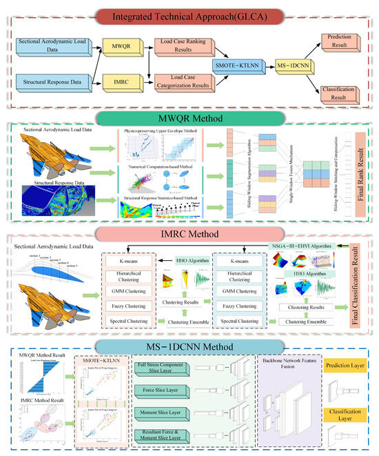
Figure 2.
The overall technical route of the GLCA method. “GCLA Operation Positioning and Functional Contributions” box details the application position of the GLCA method in actual workflows and its role. The “Integrated Technical Approach (GLCA)” box organizes the logical relationships of the sub-algorithms within the GLCA method. The “MWQR Method” box visualizes the MWQR data processing process and principles. The “IMRC Method” box visualizes the IMRC data processing process and principles. The “MS-1DCNN Method” box visualizes the principles and data processing procedures of MS-1DCNN.
3.1. Data Acquisition and Verification
All data for the GLCA method was sourced from coarse-mesh aircraft models and high-fidelity models, with data acquisition performed in HyperView 2022. Structural sections with varying densities were established throughout the airframe (including wings, vertical tail, horizontal tail, aft fuselage, mid-fuselage, and forward fuselage) for data collection, based on the load-bearing characteristics and stress concentration patterns under different flight maneuvers. For regions exhibiting higher stress concentrations—such as the aft fuselage, mid-fuselage, and wing root sections—section spacing was minimized (e.g., frame-bay spacing in the fuselage). Areas with lower stress levels, like the wingtip and forward fuselage, employed sparser section distributions. Using the FBD section force extraction tool within HyperView, an eight-dimensional load vector P was extracted at each section, containing three force components (, , ), three moment components (, , ), the resultant force (), and the resultant moment (). A total of 60 structural sections were defined across the aircraft, covering 160 load cases, yielding a sample size of 160. Figure 3 displays the locations of section setups during full-aircraft data acquisition.
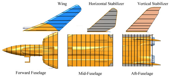
Figure 3.
The locations of section setups during full-aircraft data acquisition.
Structural response data corresponding to these 60 sections and 160 load cases was obtained by extracting stress values from all finite elements within a specified distance surrounding each section. Approximately 600–1000 stress elements were captured per section in geometrically simpler regions (e.g., wings, vertical/horizontal tails). In geometrically complex regions like the aft and mid-fuselage, element counts ranged from 3500 to 4500 per section.
Validation Criteria: (1) High-Fidelity Model Benchmark: Identical sections were defined at corresponding locations within the high-fidelity model, extracting stress values over the same ranges. The Weighted Stress State Ranking (WSSR) method—quantifying load case criticality via stress exceedance statistics—was applied to the high-fidelity stress data (treated as the accurate benchmark). The resulting criticality ranking, validated through stress contour visualization, served as the benchmark for assessing GLCA method outputs. (2) Engineering Experience and Known Critical Load Cases: The aircraft model used is validated through flight test certification. Critical load cases identified during the airframe’s load development phase constitute an established engineering benchmark. GLCA-identified critical cases were directly compared against this known benchmark to further validate the method’s effectiveness and accuracy.
3.2. Multi-Dimensional Sliding-Window Fusion-Based Risk Quantification and Rank (MWQR)
The MWRQ method generates quantified rankings of load cases by analyzing aircraft aerodynamic loads and structural response data across three distinct dimensions. The first dimension adapts the traditional load envelope concept, evaluating case criticality by defining envelope relationships through multi-level dominance criteria. Operating purely at the numerical level, the second dimension applies PCA [37], SVD [38], and CRITIC-Entropy [39] weighting to prioritize risk without relying on physical interpretation. The third dimension specifically processes structural response data, quantifying relative risk by calculating weighted global stress values based on element counts exceeding predefined stress thresholds and incorporating preset weights. To integrate the divergent rankings from these dimensions, a sliding window segmentation strategy partitions each ranking sequence. Optimal fusion strategies are determined by comparing statistical distance metrics between corresponding sub-windows. The fused sub-window rankings are subsequently concatenated to form a global comprehensive quantified ranking, with the overall process illustrated in Figure 2.
Let denote N load cases, each characterized by force parameters (components to ) and structural stress responses for K elements.
3.2.1. Multilevel Domination-Based Load Envelope (MDLE)
- Parameter normalization:where ⊘ denotes element-wise division.
- Weight synthesis:
- Domination matrix :where is domination at level ℓ:where and represent the resultant force and resultant moment of loading case i, respectively. This level aims to: (1) Characterize the multi-component coupling effects using the integral properties of resultant forces/moments; (2) Replicate the empirical practice where engineers preliminarily screen high-risk loading cases based on resultant quantities. The weight vector assigns component weights according to the structural load-bearing characteristics. The sign function maps continuous comparison results into discretized dominance relations (1: i dominates j; : j dominates i), enabling efficient identification of dominance relationships.
- Domination score:where is the indicator function. Samples are ranked by descending to generate the load envelope sequence . Higher values indicate stronger domination capability within the load space, prioritizing structurally critical load cases.
3.2.2. Multivariate Statistical and Combined Weight-Based Ranking (MSCWR)
The MSCWR methodology integrates three unsupervised learning techniques to assess load case criticality purely from numerical characteristics of force parameter data. Let denote the force parameter matrix where rows correspond to N load cases and columns represent force/moment components .
- PCA Ranking:Standardize to . Compute principal components:where is the principal component score matrix. Retain k components where eigenvalues . The PCA criticality score is as follows:where being the i-th row of (PC scores for i-th load case), , and the eigenvalue of the j-th principal component.
- SVD Ranking:Decompose the standardized matrix where contains left singular vectors, the singular value matrix, and right singular vectors. Select k such that cumulative energy . The SVD criticality score is as follows:
- CRITIC-Entropy Weighted Ranking:Min-max normalize to . CRITIC weights:where is standard deviation of j-th parameter, the correlation coefficient between parameters j and m. Entropy weights are computed viaCombined score: .
- Rank Fusion:Let denote rank index vectors from each method. The fused MSCWR ranking is as follows:where is MSCWR final rank result.
3.2.3. Weighted Stress Statistics Ranking (WSSR)
The WSSR method quantifies load case criticality through statistical analysis of stress exceedances across structural monitoring locations. For N load cases and K stress measurement locations, let denote the stress value at location k during load case i.
- Threshold exceedances:For P predefined stress thresholds with corresponding weights ,where counts the number of locations where stress during load case i exceeds threshold . Thresholds typically represent critical stress levels with weights reflecting their structural significance.
- Stress criticality score:where represents the composite criticality score for load case i. The load case ranking is obtained by sorting in descending order.
3.2.4. Sliding Window Fusion
- Segmentation:Partition rank vectors using overlapping windows:where indexes windows, L is window length, controls overlap fraction, and s is the step size. Each segment contains a subsequence of ranks.
- Distance-based fusion:For segment q, compute pairwise distances. Mean absolute difference:measuring average rank displacement where is the -norm.Kendall’s :Select fusion strategy minimizing or maximizing .
- Fused segment:
- Global reconstruction:where = count of windows containing index j. Final ranking: .
3.3. Integrated Multi-Step Refinement Methodology for Criticality Classification of Load Cases (IMRC)
Building upon the MWRQ-generated quantified rankings, the IMRC method identifies coverage, coupling, and differentiation relationships between load cases to precisely distinguish load patterns and output critical load cases. This advanced clustering algorithm employs a dual-layer structure based on local-global co-optimization. The first clustering layer applies multiple heterogeneous clustering algorithms [40,41,42,43,44] for initial classification, integrating results through an attention-based ensemble method. Using the silhouette coefficient as the optimization metric, HHO locally adjusts cluster counts and algorithm fusion weights. This layer identifies the highest-risk category by integrating results with MWRQ rankings. The second layer replicates this structure but performs refined boundary partitioning exclusively on the identified high-risk category. Both layers’ results are concatenated and globally fine-tuned using NSGA-III-EHVI to optimize hyperparameters and fusion weights. Finally, all detected load patterns are ranked by criticality using MWRQ metrics to output critical load cases. Figure 4 illustrates the algorithmic architecture of IMRC.
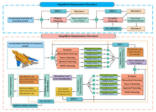
Figure 4.
IMRC technical roadmap.
The aerodynamic load data (n: load cases, d: features) is processed through a dual-layer hierarchical clustering structure. Key mathematical steps are formalized below.
3.3.1. Similarity Matrix Construction and Attention-Based Fusion
Input: processed via five clustering algorithms: K-means, Vague clustering, SOM, Hierarchical clustering, and Spectral clustering.
Output: Label vectors for each algorithm .
The similarity matrix for algorithm i is defined as follows:
The attention-weighted fusion integrates all similarity matrices:
where is normalized Silhouette coefficient. is normalized Davies–Bouldin index. is normalized Calinski–Harabasz index. is one of the optimization variables in Harris Hawks Optimization (HHO), controlling the algorithm fusion strategy.
3.3.2. Hierarchical Clustering Integration and Critical Class Identification
First-layer clustering applies average-linkage hierarchical clustering:
where is the hierarchical clustering operator and is the cluster count.
Critical class identification locates the highest-risk cluster:
where represents the MWQR risk ranking vector, with higher indicating greater criticality.
3.3.3. Local Optimization via HHO
The first-layer clustering parameters are optimized via
where is the Silhouette index.
Similarly, the second-layer optimization is as follows:
Both optimizations utilize the Harris Hawks Optimization(HHO) algorithm with escaping energy parameterization:
where t is iteration index and T is maximum iterations.
3.3.4. Global Optimization via NSGA-III-EHVI
The combined clustering solution is formed by merging both layers:
where denotes the merge operator preserving non-critical classes from and refined critical classes from .
A multi-objective optimization fine-tunes all parameters:
where . is the Silhouette index for layer ℓ. is Davies–Bouldin index for layer ℓ. is the Calinski–Harabasz index for layer ℓ. are bounds derived from HHO solutions. This constrained multi-objective problem is solved using the NSGA-III-EHVI algorithm, which efficiently handles Pareto front exploration in high-dimensional spaces.
3.3.5. Critical Load Case Output
Final criticality assessment ranks clusters by mean risk:
Class ranking:
The output is the sorted list of load cases in descending order of cluster criticality , enabling prioritized safety inspection.
3.4. Multi-Slice 1DCNN Feature Extraction Fusion for Hazard Prediction (MS-1DCNN)
To address sparse critical load cases, class imbalance, and limited samples in the initial dataset, SMOTE-KTLNN [14] is collaboratively applied with IMRC. This algorithm targets imbalanced classes for precise oversampling, enhances data through noise filtration, and improves 1DCNN prediction accuracy. Although augmented data contains class labels, quantified criticality labels require reapplication of MWRQ. As 2-3x sample expansion affects quantification, RPD-NSGAII [45] performs reference point-based adjustment using the initial dataset to ensure label correctness. The enhanced two-dimensional feature matrix exhibits complex inter-feature associations: strongly correlated features require joint analysis while decoupled features permit 1D processing. Therefore, a 1DCNN-based architecture implements feature slicing according to physical significance. Custom CNN branches extract features from subsets, with multi-source fusion in the backbone network. This MS-1DCNN approach circumvents global data updates for new load cases while enabling precise prediction. Figure 5 illustrates the holistic architectural design of the MS-1DCNN.
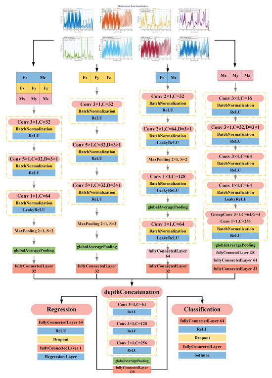
Figure 5.
Architectural diagram of the MS-1DCNN model. The eight feature vectors of aerodynamic loads undergo domain-specific segmentation as 1D signals, processed through four specialized convolutional neural networks dedicated to feature extraction per data branch. Feature fusion occurs in the backbone network, enabling simultaneous output via classification and regression heads.
3.4.1. Data Process and Augment
The process initiates with extracting structural sectional aerodynamic loads from coarse-grid aircraft models. Data cleaning and aggregation then form a 2D nominal sample feature matrix. The IMRC clustering algorithm identifies minority-class samples, followed by SMOTE oversampling. Generated samples undergo noise identification and filtering via KTLNN to remove outliers, yielding an enhanced dataset with class labels. This dataset undergoes preliminary risk severity quantification and ranking of load cases using the MWQR method, with corrections applied by the RPD-NSGAII algorithm (a reference-point-dominated multi-objective genetic algorithm): initial dataset serves as reference points to adjust quantification labels, ensuring accurate risk assessment. The final output is a 2D feature matrix with calibrated risk severity labels. Figure 6 illustrates the data preprocessing workflow for MS-1DCNN prior to training.
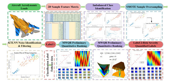
Figure 6.
MS-1DCNN data preprocessing workflow diagram. First, extract aerodynamic load data from various parts of the aircraft to form a “2D Sample Feature Matrix”, use the IMRC method to locate “Imbalance Class Identification”, implement “SMOTE Sample Oversampling” for the unbalanced classes to achieve preliminary class balance, then move into the “KTLNN Noise Identification & Filtering” stage to eliminate noise from the newly added samples, resulting in the category label for “Label 1” samples. Use the MWQR method to sort the downsampled samples, and introduce the RPD-NSGAII algorithm to modify the risk scores, resulting in “Label 2: Risk Severity Quantified Labels”.
3.4.2. SMOTE-KTLNN Algorithm
Given the initial dataset with and , minority classes are identified as follows:
where denotes the label space. For each , synthetic samples are generated via SMOTE oversampling:
where is a minority-class sample and is a randomly selected k-nearest neighbor. The balanced dataset is subsequently filtered through iterative kTLNN denoising:
- Random Partitioning: At iteration t, shuffle and partition into P subsets
- Ensemble Voting: For each subset , train kTLNN classifier and compute error votes:
- Noise Identification: Flag samples where majority classifiers err:
- Termination Condition: Update and terminate when:
The purified dataset achieves class balance and noise robustness.
3.4.3. Hazard Quantification Correction
Danger-level labels of are calibrated via RPD-NSGAII multi-objective optimization. Using as reference, weight vector is optimized:
where are MDLE-based evaluation metrics. The optimal reprojects danger-level labels to maintain physical consistency.
3.4.4. Architectural Design of the MS-1DCNN Network
Post-processing enables the augmented dataset to fully meet deep 1DCNN training requirements. Direct classification/prediction using initial samples yields suboptimal accuracy (<95%). To address this, features are decoupled and sliced according to physical significance, forming dedicated feature subsets. Specialized convolutional sub-networks extract features from each subset. Extracted features undergo fusion and high-level re-identification in the backbone network, with parallel classification heads (outputting case categories) and regression heads (outputting predicted values) generating final predictions.
The network architecture employs feature-space decoupling and multi-branch fusion, constructing dedicated 1D convolutional sub-networks for physically significant feature subsets. Input signals decompose into four parallel slices: full-feature, force-feature, moment-feature, and combined force/moment feature. Full/force-feature sub-networks adopt a triple-stage cascade comprising standard convolution (kernel [3,1]), dilated convolution (kernel [5,1], dilation [3,1]), and 1 × 1 refinement modules, outputting 32-D vectors via global average pooling and fully connected layers. For moment-features, an enhanced sub-network incorporates a third convolution layer (kernel [3,1]), depthwise separable convolution, and dual fully connected layers, expanding channels to 256 while preserving kernel dimensions to strengthen complex moment pattern representation. The combined force/moment sub-network utilizes quadruple convolutional layers. Within the backbone, four 32-D features undergo deep concatenation followed by three progressively refined convolutional modules: kernel sizes decreasing from [5,1] to [2,1] while channels increase from 64 to 256, enabling fine-grained feature expression. Final predictions are generated through fully connected layers and parallel output heads.
4. Experiments
The effectiveness and practicality of the GLCA methodology were validated through quantitative and qualitative comparisons of load spectra at critical full-aircraft locations against high-fidelity finite element models. Self-consistency metrics and physical rationality in intermediate processes further demonstrate methodological correctness. Computational efficiency was confirmed by comparing processing times for equivalent load cases, revealing GLCA’s significant efficiency advantage over high-fidelity analysis.
4.1. Verification of the Effectiveness of the MWQR Method
Post-processing of high-fidelity finite element analysis results enables precise derivation of load case criticality rankings. Across all critical sections of the full aircraft, four quantitative metrics are employed to evaluate consistency between MWRQ results and high-fidelity model analyses. The metric formulas are defined as follows:
where is Spearman’s rank correlation coefficient, where denotes the difference in ranks for the i-th component, and n is the total number of components. is Kendall’s tau correlation coefficient, where counts concordant pairs, counts discordant pairs, and adjust for ties in rankings. is the Mean rank difference, with and representing ranks assigned by MWQR and high-fidelity models respectively. is the Warning rate indicating the proportion of components exceeding the acceptable rank deviation threshold, where is the critical threshold ratio, and is the indicator function.
Quantitative analysis: Table 1 data demonstrates strong overall consistency between MWRQ and high-fidelity FEM across major aircraft structures, though regional variations exist. All structural sections exhibit Spearman rank correlation coefficients > 0.94 (wing: 0.9824, forward fuselage: 0.9794) and Kendall coefficients > 0.83 (wing/forward fuselage: 0.9167), confirming high reliability in load case criticality ranking–particularly for primary load-bearing components like wings. Quantitative analysis reveals mean difference ranges from 0.50 (wing) to 1.13 (aft-fuselage), with warning rates between 7.50% (wing/horizontal stabilizer) and 13.75% (aft-fuselage). This indicates marked methodatic deviation and elevated warning rates in the aft-fuselage region, reflecting its heightened sensitivity to model simplification due to structural complexity. Though vertical stabilizer (12.50%) and mid-fuselage (11.25%) show higher warning rates than wings, their ranking correlations (Spearman > 0.95) remain robust.

Table 1.
Structural areas performance metrics.
Qualitative analysis: Figure 7 illustrates a scatter plot illustrating the risk ratings of different load cases (where the x/y axes represent section force/moment, with higher values indicating greater risk). Color corresponds to the GLCA-derived risk level (higher numerical values denote higher risk). The results demonstrate a clear increase in risk level with rising section loads, validating the rationality of the GLCA approach. The plot explicitly demarcates regions identified by GLCA as safe (green) and critical (red) load cases, suggesting these regions guide structural optimization. Benefiting from the “coarse localization and fine classification” dual-layer clustering strategy, the critical load case categories are few in number yet exhibit high identification precision. Furthermore, load cases within each category share similar loading patterns and are prioritized. This enables engineers to efficiently assess risks during the detailed design phase by analyzing only a few representative cases possessing the highest priority within each category.
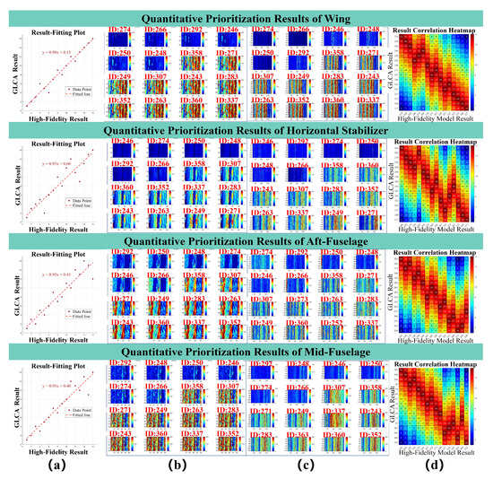
Figure 7.
Visual comparison of the MWQR method and high-fidelity model analysis. Results for critical locations are presented: (a) Linear fit plot of quantitative ranking results. Panel (b) shows the FEA stress nephogram of the coarse-mesh model ranked by the MWQR method, where the stress nephogram is mapped onto a 2D plane for intuitive visualization of stress levels; the top-left corner represents the safest load case, and the bottom-right corner the most hazardous. Panel (c) displays the ranking results from high-fidelity model FEA, with its stress nephogram similarly mapped. Panel (d) presents the correlation heatmap between the MWQR method and high-fidelity model analysis results.
4.2. Verification of the Effectiveness of the IMRC Method
Quantitative Analysis: Table 2 demonstrates excellent load pattern clustering performance of the IMRC method across all aircraft sections. All sections achieve Silhouette Coefficients > 0.7 (horizontal stabilizer: 0.8530) and Davies–Bouldin (DB) indices < 0.66 (horizontal stabilizer: 0.4295), validating strong intra-class compactness and inter-class separation. Calinski–Harabasz (CH) indices further confirm clustering effectiveness, with outstanding performance in the forward fuselage (869.0453), horizontal stabilizer (704.9135), and wing (568.1503). The vertical stabilizer (129.4874) shows significantly lower CH values, reflecting potential clustering discrimination challenges due to complex load patterns. Collectively, these metrics confirm IMRC’s capability to distinguish load cases into highly discriminative patterns, establishing a reliable foundation for critical load case identification.
Table 2.
Clustering evaluation metrics for aircraft structural components.
Qualitative Analysis: Figure 8 illustrates load pattern clustering and critical load identification results across aircraft sections. IMRC’s dual-layer clustering structure demonstrates a distinct hierarchy: safer load case categories exhibit broader boundaries, while extreme-risk categories maintain stringent, finely partitioned limits. Given axes representing force/moment magnitudes (greater values indicate higher criticality), all identified critical load cases align with high-value regions, confirming engineering validity.
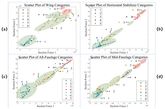
Figure 8.
Scatter plot of IMRC classification categories. (a) displays the analysis results for the wing section, recommending an in-depth analysis of load cases categorized under the fifth and sixth risk levels. (b) presents the results for the horizontal tail section, which exhibits relatively low geometric complexity, resulting in clearly defined boundaries for critical load case regions. Subfigure (c) shows the results for the aft fuselage section. Despite its higher geometric and loading complexity (representing a greater analysis challenge than the wing), GLCA rationally identified load cases categorized under the fifth, sixth, and seventh risk levels as critical categories. (d) displays the results for the mid fuselage section, where the loading patterns are comparatively straightforward, leading to well-defined boundaries for critical load cases.
Figure 9 distinctly illustrates divergent convergence characteristics between the locally optimized HHO algorithm and the globally optimized NSGA-III-EHVI. HHO-1 and HHO-2 demonstrate progressive convergence from initially dispersed search spaces toward optimal regions (Figure 9a,b), validated by rapid energy decay curves (Figure 9c). NSGA-III-EHVI, deployed for global fine-tuning, explores optimal parameter spaces within the dual-layer clustering mechanism (Figure 9a,b), generating Pareto front solution sets (bold blue line, Figure 9c) exhibiting non-dominated characteristics in high-dimensional objectives. Both algorithms exhibit rational optimization trajectories.
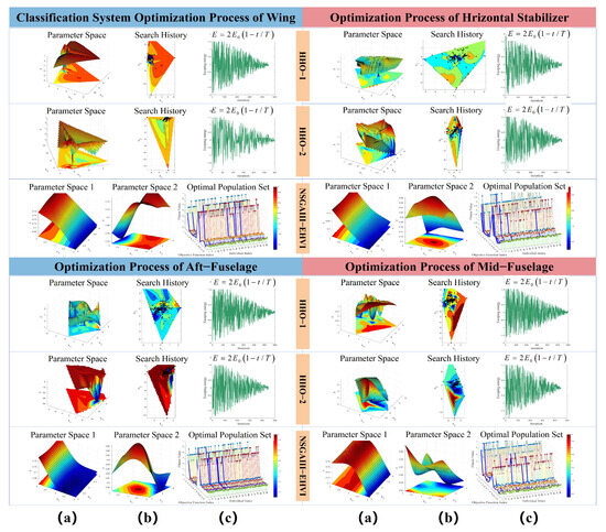
Figure 9.
Optimization search and convergence processes for multiple optimization algorithms. (a) Parameter search spaces for the HHO algorithm and NSGA-III-EHVI algorithm; (b) HHO algorithm’s search history for optimal solutions; NSGA-III-EHVI algorithm’s parameter search space in the secondary IMRC layer; (c) Energy consumption profile during HHO search execution; Pareto front visualization of NSGA-III-EHVI optimal solutions.
Figure 10 validates IMRC effectiveness through high-fidelity stress contour visualizations. Load pattern criticality distributions (color-coded) exhibit strong alignment with finite element stress fields. Critical load cases display pronounced stress concentrations spatially consistent with IMRC-identified critical regions.
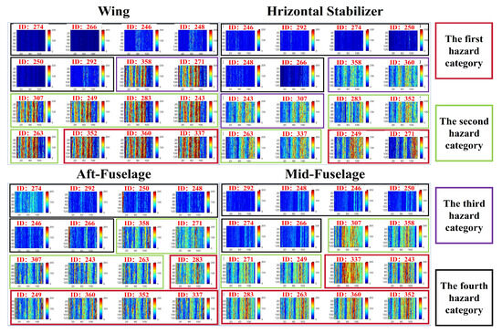
Figure 10.
Load pattern criticality classification diagram. Color-coded regions distinguish load patterns by danger level, with red zones denoting critical load cases and green zones indicating conditions requiring heightened attention.
4.3. Verification of the Effectiveness of the MS-1DCNN Method
Quantitative Analysis: Table 3 evaluates MS-1DCNN prediction performance using R2, RMSE, MAE, and MBE metrics. Results demonstrate exceptional accuracy across all aircraft sections, with values exceeding 0.9889 (all >0.99 except horizontal stabilizer: 0.9889; mid-fuselage peak: 0.9976), indicating superior data variance capture. RMSE values remain below 12.4370 (<5% total error), confirming prediction reliability. MAE ranges from 3.6115 (mid-fuselage) to 10.1137 (horizontal stabilizer), reflecting minimal error magnitudes. Consistently negative MBE values indicate methodatic underestimation, particularly pronounced in wing components compared to more stable tubular structures like fuselage sections.
Table 3.
MS-1DCNN Prediction Evaluation Metric.
Qualitative Analysis: Figure 11 illustrates MS-1DCNN’s predictive performance across critical aircraft sections. Training set results (Figure 9a) exhibit consistently low errors, while test set performance (Figure 9b) shows marginally higher yet well-contained errors, indicating strong generalization capability without overfitting. Prediction–actual value regressions (Figure 9c) reveal high linear correlation across all structures, confirming accurate target value estimation. The prediction error distribution (Figure 9d) displays an approximately normal pattern centered near zero, verifying minimal random errors with no methodatic bias, thus affirming model reliability and robustness.
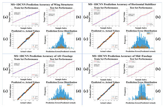
Figure 11.
MS-1DCNN prediction results: training vs. test sets. (a) training set predictions; (b) test set predictions; (c) prediction–actual value regression comparison; (d) prediction error distribution plot.
Quantitative Analysis: As presented in Table 4, the MS-1DCNN model demonstrated outstanding performance in classifying the hazard levels of load cases across different aircraft structural components. The model achieved average classification accuracies exceeding 96.5% for all components, indicating its reliable identification capability for the hazard levels of most load cases. The model also exhibited strong performance in terms of Precision and Recall, particularly for the vertical tail and horizontal tail, where both metrics approached 0.99. The F1-score, a comprehensive metric reflecting both Precision and Recall, remained consistently high, further validating the model’s superior overall classification performance.
Table 4.
MS-1DCNN classification performance.
Figure 12 illustrates the classification performance per category for different structural components, along with the confusion matrices for both the training and test sets, validating the exceptional classification performance of MS-1DCNN across various structural locations.
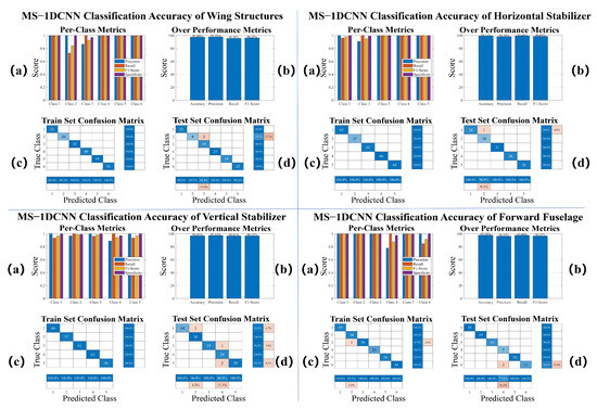
Figure 12.
Classification performance of MS-1DCNN across different structural locations. (a) Performance metrics per category. (b) Overall classification performance metrics. (c) Training set classification confusion matrix. (d) Test set classification confusion matrix.
4.4. Computational Efficiency Comparison
Table 5 summarizes the execution times of existing load case analysis methods and the critical load case identification process, along with the training time of the MS-1DCNN model, to quantify the computational efficiency for a single structural section.
Table 5.
Model running time display.
As shown in Table 6, the GLCA method significantly outperforms high-fidelity finite element analysis (FEA) in computational efficiency for load case analysis and critical load case selection. Following the completion of the initial load case analysis, this method can rapidly predict the hazard level of newly added load cases without recalculation, thereby further shortening the analysis cycle. It should be specifically noted that the comparison results only include the computation time of the high-fidelity FEA; if the time required to establish the high-fidelity model is considered, the actual efficiency gap would be more pronounced.
Table 6.
Comparison of computational time between FEA and GLCA.
4.5. Experimental Validation of HHO and NSGA-III-EHVI Optimization Algorithm Superiority
Control groups were established by systematically substituting mainstream algorithms (NSGA-II + NSGA-III-EHVI, HHO + MOEA). Clustering performance for four primary load-bearing components (wing, horizontal tail, rear fuselage, center fuselage) was evaluated using the Silhouette Coefficient, Davies–Bouldin index, and Calinski–Harabasz index. As shown in Supplementary Material Table S1, the HHO+NSGA-III-EHVI combination demonstrated significantly superior performance compared to mainstream optimization algorithms. It achieved increases in Silhouette Coefficient ranging from 23.9% to 39.1%, and an average reduction of 12.8% in the Davies–Bouldin index across all four components. This combination adapts to irregular geometric topologies via HHO’s discrete optimization capability and dynamically optimizes high-dimensional reference point distribution based on the EHVI criterion within NSGA-III-EHVI, effectively mitigating the local solution clustering defect inherent in MOEAs caused by weight mismatch.
4.6. Ablation Study on the SMOTE-KTLNN Module
Performance comparisons of the MS-IDCNN model with and without the SMOTE-KTLNN module (Supplementary Material Tables S2 and S3) reveal: (1) Prediction Performance: Removal of SMOTE-KTLNN resulted in an average increase of 206% in test set RMSE (reaching 417% for the center fuselage) and a reduction of the coefficient of determination below 0.98, demonstrating the module’s indispensability for generalization capability in geometrically complex regions (e.g., center fuselage, rear fuselage). (2) Classification Performance: Ablation led to comprehensive degradation in test set classification performance, particularly severe for the rear fuselage (F1-score dropped to 0.41) and forward fuselage (F1-score decreased by 57%), confirming that the module significantly enhances classification robustness for complex structures by optimizing inter-class imbalances.
4.7. Noise Immunity Experiment for the GLCA
- Supplementary Material Table S4 demonstrates the robust feature ranking stability of the MWRQ method: Both Spearman and Kendall coefficients exceeded 0.8 across all regions, with the wing achieving optimal values (0.9765/0.8833), while the horizontal tail showed a significant decrease (0.9088/0.8000). Feature deviation values remained below the 5% reliability threshold (extremes: horizontal tail 1.5000, wing 0.5000).
- Supplementary Material Table S5 indicates that noise impact on the IMRC module’s clustering quality was controlled: The horizontal tail exhibited optimal performance (Silhouette Coefficient: 0.8502→0.8530, Davies–Bouldin index: 0.3900→0.4295). Although the wing’s Silhouette Coefficient decreased, its Calinski–Harabasz index increased to 593.1540. The forward fuselage displayed significant sensitivity (Silhouette Coefficient: 0.6980→0.7553). Core metric fluctuations remained below 5%, validating the reliability of load pattern recognition.
- In the noise resilience experiment (Supplementary Material Table S6), key metric fluctuations for the MS-IDCNN prediction model fell within acceptable engineering tolerances: The wing demonstrated exceptional stability (R2 decreased only 0.0038, RMSE improved by 15.7%). The horizontal tail R2 increased to 0.9919 despite an RMSE rise to 13.9781. The forward fuselage R2 maintained 0.9923, while the center fuselage showed greater sensitivity (RMSE increased to 13.5203).
- Supplementary Material Table S7 further confirms the strong robustness of the MS-IDCNN classification model: Classification metric fluctuations across regions were minimal (maximum accuracy fluctuation: 2.3%; maximum F1-score fluctuation: 0.7%), with localized performance improvements observed (e.g., wing accuracy: 97.50%→97.92%; forward fuselage F1-score: 0.9675→0.9811). All regions maintained accuracy > 96.8% and F1-score > 0.95.
4.8. Ablation Study on the HHO and NSGA-III-EHVI Optimization Algorithms
(1) Single-optimization control groups were constructed by excluding either HHO or NSGA-III-EHVI (Supplementary Material Table S8): Retaining only HHO improved local clustering quality (e.g., wing Calinski–Harabasz index: 818.58) but deteriorated global-level metrics, resulting in entrapment in local optima. (2) Retaining only NSGA-III-EHVI led to unstable global optimization (e.g., center fuselage Silhouette Coefficient decreased by 23%) and degraded local clustering quality. (3) Synergistic Mechanism: HHO provides near-optimal initial solutions for each clustering layer (e.g., horizontal tail Calinski–Harabasz index: 1254), while NSGA-III-EHVI performs global fine-tuning, achieving a balance between local quality and global optimality. The experiments demonstrate that the collaborative optimization between the HHO and NSGA-III-EHVI algorithms is crucial for the classification stability of IMRC.
5. Conclusions
This paper proposes a Global Load Case Analysis (GLCA) method, providing a comprehensive solution for efficiently identifying critical load cases in aircraft structural load development. Traditional approaches relying on high-fidelity finite element analysis for critical load case identification impede structural iterative optimization due to high computational and time costs, while existing methods suffer from subjective experience dependence, complex manual operations, and limitations to component-level analysis. GLCA overcomes these limitations by leveraging coarse-mesh model data to drive three analytical models. Based on experimental results, the main conclusions are as follows:
- (1)
- The MWRQ method integrates physical-informed envelope analysis, multivariate numerical computation, and stress exceedance statistics to objectively quantify and rank the criticality of global load cases. Its ranking maintains over 94% consistency with high-fidelity model rankings across all aircraft structural sections, with analysis time per section being only 32.2 s. This provides engineers with a rapid load case assessment tool during the preliminary structural design phase, facilitating early optimization of structural layout and aerodynamic shape.
- (2)
- The IMRC method employs the HHO algorithm and NSGA-III-EHVI algorithm to optimize a bi-layer clustering structure, integrating clustering methods of different principles to accurately partition load patterns (Silhouette > 0.7 for all sections) and determine risk classifications for global load cases, enabling rapid identification of critical load cases. It recommends load cases guiding structural optimization to engineers during the transition from preliminary to detailed design stages, accelerating the iterative aircraft structural optimization process.
- (3)
- The MS-1DCNN method addresses data class imbalance and limited sample size via SMOTE-KTLNN. It trains an aircraft-type-specific load case analysis prediction model through multi-slice training and feature fusion, rapidly predicting the risk level of new load cases (R2 > 0.98, Accuracy > 96.8%). This method effectively handles supplementary load cases arising from newly exposed issues in design iterations, limitations of analytical methods, or changing external constraints, eliminating the need for full global load case reanalysis.
- (4)
- The GLCA method completes analysis of 60 structural sections and 160 load cases, including 1DCNN model training, within 12 h. It operates via a HyperView plugin and executable software without requiring specialized computational resources. In contrast, a single load case analysis in high-fidelity models requires nearly 24 h due to extensive meshing, with high hardware demands for finite element analysis. GLCA demonstrates significant advantages in hardware cost and time consumption, accelerating aircraft structural iterative optimization.
In summary, GLCA provides a practical load case analysis tool for both preliminary and detailed aircraft structural design phases. It reduces the load case analysis cycle to under 12 h, effectively overcoming existing limitations of heavy reliance on subjective experience, operational complexity, and component-level analysis scope, while demonstrating notable advantages in computational efficiency and cost-effectiveness. It should be noted that GLCA is built upon coarse-mesh model data, and its accuracy is constrained by the reliability of the stress fields computed from this model; consequently, the analysis results are subject to some influence from load simplification errors and inherent stress approximations.
6. Future Work
While the GLCA system provides an efficient global load case analysis framework for the early aircraft design stage, its limitations also highlight critical pathways for subsequent research: To address the reliability issues of stress fields derived from coarse-mesh models, an aero-structure coupled multiscale simulation strategy will be pursued. This will involve embedding high-fidelity submodels in critical stress concentration zones, establishing coarse-to-fine mesh stress mapping relationships via machine learning, and dynamically refining the statistical threshold for WSSR to enable accurate stress exceedance statistics. This approach balances computational efficiency with precision.
Supplementary Materials
The following supporting information can be downloaded at: https://www.mdpi.com/article/10.3390/act14080406/s1, Table S1: Superiority Validation of HHO and NSGA-III-EHVI Optimization Algorithms; Table S2: Impact of Ablation Study on SMOTE-KTLNN for MS-1DCNN Predictive Performance; Table S3: Impact of SMOTE-KTLNN Ablation Study on MS-1DCNN Classification Performance; Table S4: MWRQ method anti-noise experiment; Table S5: IMRC Robustness Assessment Under Noise; Table S6: Noise Immunity of MS-1DCNN Prediction Performance; Table S7: Classification Performance Integrity of MS-1DCNN Under Noise; Table S8:Ablation experiment of HHO algorithm and NSGAIII-EHVI algorithm.
Author Contributions
Y.L.: Writing—Original Draft, Methodology, Visualization, Conceptualization; K.Z.: Writing—Review and Editing; X.L.: Writing—Review and Editing; Q.X.: Supervision, Project administration, Validation, Funding acquisition. All authors have read and agreed to the published version of the manuscript.
Funding
This work was financially supported by: the Shandong Provincial Natural Science Foundation (ZR2023QE118), Key Technology Research and Development Program of Shandong Province (2024JMRH0207), Laboratory Construction and Management Research Project of Shandong University (sy20242301).
Informed Consent Statement
Informed consent was obtained from all subjects involved in the study.
Data Availability Statement
Data will be made available on request.
Acknowledgments
HyperMesh 2022 was employed for acquiring internal force data of aircraft structural sections, HyperView 2022 for collecting structural response data, and MATLAB 2024 for implementing core algorithms and software development of the GLCA methodology throughout this study.
Conflicts of Interest
The authors declare that they have no known competing financial interests or personal relationships that could have appeared to influence the work reported in this paper.
Abbreviations
The following abbreviations are used in this manuscript:
| GLCA | Global Load Case Analysis method |
| MWQR | Multi-dimensional Sliding-Window Fusion-based Risk Quantification and Ran |
| IMRC | Integrated Multi-step Refinement Methodology for Criticality Classification of Load Cases |
| MS-1DCNN | Multi-Slice 1DCNN Feature Extraction Fusion for Hazard Prediction |
| HHO | Harris Hawks Optimization |
| NSGAIII-EHVI | Nondominated Sorting Genetic Algorithm III - Expected Hypervolume Improvement |
| RPD-NSGAII | Reference Point-based Dominance—nondominated sorting genetic algorithm-II |
| SMOTE-KTLNN | Minority Oversampling Technique—a two-layer nearest neighbor classifier |
References
- Goranson, U.G. Fatigue issues in aircraft maintenance and repairs. Int. J. Fatigue 1998, 20, 413–431. [Google Scholar] [CrossRef]
- Tavares, S.; De Castro, P. An overview of fatigue in aircraft structures. Fatigue Fract. Eng. Mater. Struct. 2017, 40, 1510–1529. [Google Scholar] [CrossRef]
- Dharmasaroja, A.; Armstrong, C.; Murphy, A.; Robinson, T.; McGuinness, S.; Iorga, N.; Barron, J. Load case characterization for the aircraft structural design process. AIAA J. 2017, 55, 2783–2792. [Google Scholar] [CrossRef]
- Sferza, M.; Ninić, J.; Chronopoulos, D.; Glock, F.; Daoud, F. M2ltidisciplinary Optimisation of Aircraft Structures with Critical Non-Regular Areas: Current Practice and Challenges. Aerospace 2025, 8, 223. [Google Scholar] [CrossRef]
- Haider, A. Efficiency enhancement techniques in finite element analysis: Navigating complexity for agile design exploration. Aircr. Eng. Aerosp. Technol. 2024, 96, 662–668. [Google Scholar] [CrossRef]
- Nazzeri, R.; Haupt, M.; Lange, F.; Sebastien, C. Selection of Critical Load Cases Using an Artificial Neural Network Approach for Reserve Factor Estimation; Deutsche Gesellschaft für Luft-und Raumfahrt-Lilienthal-Oberth eV: Bonn Germany, 2015. [Google Scholar]
- Dang, X. General Editorial Boardof Aircraft Design Manual. Aircraft Design Manual: Vol.9-Loads, Strengthandstiffness; AviationIndustry Press: Beijing, China, 2001; pp. 55–63. [Google Scholar]
- Dharmasaroja, A.; Armstrong, C.; Murphy, A.; Robinson, T.; Iorga, N.; Barron, J. Structural performance envelopes in load space. Aeronaut. J. 2021, 125, 127–150. [Google Scholar] [CrossRef]
- Sheshanarayana, S.; Dharmasaroja, A.; Armstrong, C.; Robinson, T.; Murphy, A.; Barron, J. Calculating Implicit Reserve Factor Sensitivities from Performance Envelopes. In Proceedings of the 2018 AIAA/ASCE/AHS/ASC Structures, Structural Dynamics, and Materials Conference, Kissimmee, FL, USA, 8–12 January 2018; p. 1655. [Google Scholar]
- Heidari, A.A.; Mirjalili, S.; Faris, H.; Aljarah, I.; Mafarja, M.; Chen, H. Harris hawks optimization: Algorithm and applications. Future Gener. Comput. Syst. 2019, 97, 849–872. [Google Scholar] [CrossRef]
- Pang, Y.; Wang, Y.; Zhang, S.; Lai, X.; Sun, W.; Song, X. An expensive many-objective optimization algorithm based on efficient expected hypervolume improvement. IEEE Trans. Evol. Comput. 2022, 27, 1822–1836. [Google Scholar] [CrossRef]
- Tian, Y.; Cheng, R.; Zhang, X.; Jin, Y. PlatEMO: A MATLAB platform for evolutionary multi-objective optimization [educational forum]. IEEE Comput. Intell. Mag. 2017, 12, 73–87. [Google Scholar] [CrossRef]
- Pang, Y.; Hu, Z.; Zhang, S.; Guo, G.; Song, X.; Kan, Z. Co-design of an unmanned cable shovel for structural and control integrated optimization: A highly heterogeneous constrained multi-objective optimization algorithm. Appl. Energy 2024, 376, 124325. [Google Scholar] [CrossRef]
- Sun, P.; Wang, Z.; Jia, L.; Xu, Z. SMOTE-kTLNN: A hybrid re-sampling method based on SMOTE and a two-layer nearest neighbor classifier. Expert Syst. Appl. 2024, 238, 121848. [Google Scholar] [CrossRef]
- Harbola, S.; Coors, V. One dimensional convolutional neural network architectures for wind prediction. Energy Convers. Manag. 2019, 195, 70–75. [Google Scholar] [CrossRef]
- Zhang, Y.; Zhou, Z.; Du, Y.; Shen, J.; Li, Z.; Yuan, J. A data transfer method based on one dimensional convolutional neural network for cross-building load prediction. Energy 2023, 277, 127645. [Google Scholar] [CrossRef]
- Wang, H.; Liu, Z.; Peng, D.; Qin, Y. Understanding and learning discriminant features based on multiattention 1DCNN for wheelset bearing fault diagnosis. IEEE Trans. Ind. Inform. 2019, 16, 5735–5745. [Google Scholar] [CrossRef]
- Murawski, K.; Arciszewski, T.; De Jong, K. Evolutionary computation in structural design. Eng. Comput. 2000, 16, 275–286. [Google Scholar] [CrossRef]
- Vincenzi, L.; Gambarelli, P. A proper infill sampling strategy for improving the speed performance of a surrogate-assisted evolutionary algorithm. Comput. Struct. 2017, 178, 58–70. [Google Scholar] [CrossRef]
- Huang, Z.; Wang, C.; Chen, J.; Tian, H. Optimal design of aeroengine turbine disc based on kriging surrogate models. Comput. Struct. 2011, 89, 27–37. [Google Scholar] [CrossRef]
- Fuerle, F.; Sienz, J. Decomposed surrogate based optimization of carbon-fiber bicycle frames using Optimum Latin Hypercubes for constrained design spaces. Comput. Struct. 2013, 119, 48–59. [Google Scholar] [CrossRef]
- Viana, F.A.; Simpson, T.W.; Balabanov, V.; Toropov, V. Special section on multidisciplinary design optimization: Metamodeling in multidisciplinary design optimization: How far have we really come? AIAA J. 2014, 52, 670–690. [Google Scholar] [CrossRef]
- Simpson, T.W.; Poplinski, J.D.; Koch, P.N.; Allen, J.K. Metamodels for computer-based engineering design: Survey and recommendations. Eng. Comput. 2001, 17, 129–150. [Google Scholar] [CrossRef]
- Grihon, S.; Krog, L.; Bassir, D. Numerical optimization applied to structure sizing at AIRBUS: A multi-step process. Int. J. Simul. Multidiscip. Des. Optim. 2009, 3, 432–442. [Google Scholar] [CrossRef]
- Grihon, S. Structure sizing optimization capabilities at airbus. In Proceedings of the World Congress of Structural and Multidisciplinary Optimisation, Braunschweig, Germany, 5–9 June 2017; Springer: Berlin/Heidelberg, Germany, 2017; pp. 719–737. [Google Scholar]
- Grihon, S.; Samuelides, M.; Merval, A.; Remouchamps, A.; Bruyneel, M.; Coslon, B.; Hertel, K. Fuselage structure optimization. In Advances in Collaborative Civil Aeronautical Multidisciplinary Design Optimization; American Institute of Aeronautics and Astronautics: Reston, VA, USA, 2010. [Google Scholar]
- Liu, Y.; Yan, Z. Research on the Critical Loads Selecting Methods for the Civil Aircraft. In The Proceedings of the 2018 Asia-Pacific International Symposium on Aerospace Technology (APISAT 2018), 9th ed.; Springer: Berlin/Heidelberg, Germany, 2019; pp. 2849–2856. [Google Scholar]
- Wright, J.R.; Cooper, J.E. Introduction to Aircraft Aeroelasticity and Loads; John Wiley & Sons: Hoboken, NJ, USA, 2008; Volume 18. [Google Scholar]
- Sheshanarayana, S.; Armstrong, C.G.; Murphy, A.; Robinson, T.T.; Iorga, N.L.; Barron, J. Efficient methods to build structural performance envelopes in characteristic load space. Comput. Struct. 2025, 306, 107595. [Google Scholar] [CrossRef]
- Kiranyaz, S.; Ince, T.; Hamila, R.; Gabbouj, M. Convolutional Neural Networks for patient-specific ECG classification. In Proceedings of the 2015 37th Annual International Conference of the IEEE Engineering in Medicine and Biology Society (EMBC), Milan, Italy, 25–29 August 2015; pp. 2608–2611. [Google Scholar] [CrossRef]
- Kiranyaz, S.; Ince, T.; Gabbouj, M. Real-Time Patient-Specific ECG Classification by 1-D Convolutional Neural Networks. IEEE Trans. Biomed. Eng. 2016, 63, 664–675. [Google Scholar] [CrossRef] [PubMed]
- Kiranyaz, S.; Ince, T.; Gabbouj, M. Personalized Monitoring and Advance Warning System for Cardiac Arrhythmias. Sci. Rep. 2017, 7, 9270. [Google Scholar] [CrossRef] [PubMed]
- Abdeljaber, O.; Avci, O.; Kiranyaz, S.; Gabbouj, M.; Inman, D.J. Real-time vibration-based structural damage detection using one-dimensional convolutional neural networks. J. Sound Vib. 2017, 388, 154–170. [Google Scholar] [CrossRef]
- Avci, O.; Abdeljaber, O.; Kiranyaz, S.; Hussein, M.; Inman, D.J. Wireless and real-time structural damage detection: A novel decentralized method for wireless sensor networks. J. Sound Vib. 2018, 424, 158–172. [Google Scholar] [CrossRef]
- Abdeljaber, O.; Avci, O.; Kiranyaz, M.S.; Boashash, B.; Sodano, H.; Inman, D.J. 1-D CNNs for structural damage detection: Verification on a structural health monitoring benchmark data. Neurocomputing 2018, 275, 1308–1317. [Google Scholar] [CrossRef]
- Kiranyaz, S.; Gastli, A.; Ben-Brahim, L.; Al-Emadi, N.; Gabbouj, M. Real-Time Fault Detection and Identification for MMC Using 1-D Convolutional Neural Networks. IEEE Trans. Ind. Electron. 2019, 66, 8760–8771. [Google Scholar] [CrossRef]
- Maćkiewicz, A.; Ratajczak, W. Principal components analysis (PCA). Comput. Geosci. 1993, 19, 303–342. [Google Scholar] [CrossRef]
- Akritas, A.G.; Malaschonok, G.I. Applications of singular-value decomposition (SVD). Math. Comput. Simul. 2004, 67, 15–31. [Google Scholar] [CrossRef]
- Lu, H.; Zhao, Y.; Zhou, X.; Wei, Z. Selection of Agricultural Machinery Based on Improved CRITIC-Entropy Weight and GRA-TOPSIS Method. Processes 2022, 10, 266. [Google Scholar] [CrossRef]
- Likas, A.; Vlassis, N.; Verbeek, J.J. The global k-means clustering algorithm. Pattern Recognit. 2003, 36, 451–461. [Google Scholar] [CrossRef]
- Zhao, Y.; Karypis, G.; Fayyad, U. Hierarchical clustering algorithms for document datasets. Data Min. Knowl. Discov. 2005, 10, 141–168. [Google Scholar] [CrossRef]
- Döring, C.; Lesot, M.J.; Kruse, R. Data analysis with fuzzy clustering methods. Comput. Stat. Data Anal. 2006, 51, 192–214. [Google Scholar] [CrossRef]
- Ding, L.; Li, C.; Jin, D.; Ding, S. Survey of spectral clustering based on graph theory. Pattern Recognit. 2024, 151, 110366. [Google Scholar] [CrossRef]
- Vesanto, J.; Alhoniemi, E. Clustering of the self-organizing map. IEEE Trans. Neural Netw. 2000, 11, 586–600. [Google Scholar] [CrossRef]
- Gu, Q.; Chen, H.; Chen, L.; Li, X.; Xiong, N.N. A many-objective evolutionary algorithm with reference points-based strengthened dominance relation. Inf. Sci. 2021, 554, 236–255. [Google Scholar] [CrossRef]


Disclaimer/Publisher’s Note: The statements, opinions and data contained in all publications are solely those of the individual author(s) and contributor(s) and not of MDPI and/or the editor(s). MDPI and/or the editor(s) disclaim responsibility for any injury to people or property resulting from any ideas, methods, instructions or products referred to in the content. |
© 2025 by the authors. Licensee MDPI, Basel, Switzerland. This article is an open access article distributed under the terms and conditions of the Creative Commons Attribution (CC BY) license (https://creativecommons.org/licenses/by/4.0/).