1. Introduction
The control of underactuated mechanical systems has become a cornerstone topic in nonlinear and intelligent control engineering, with applications spanning robotics, aerospace, vehicle dynamics, and human–machine interaction [
1,
2,
3]. Among the benchmark systems used to study underactuation and nonlinear dynamics, the Furuta pendulum [
4] has emerged as a canonical platform due to its structural simplicity, strong nonlinearities, and practical relevance. Its typical configuration—consisting of a horizontal rotary base and a vertically mounted pendulum—presents significant challenges in stabilization and control design, particularly under constraints such as limited actuation, joint backlash, or delayed feedback [
5,
6,
7].
Due to these complexities, the Furuta pendulum continues to serve as a valuable surrogate for the development and validation of advanced control strategies, including energy-based methods, hybrid architectures, and model predictive control [
8,
9]. Recent contributions further highlight its ongoing relevance: Malik et al. [
10] introduced a Sand Cat Swarm Optimization (SCSO)-based state-feedback controller aimed at open-loop unstable nonlinear systems, using the Furuta pendulum as one of the testbeds. Their results demonstrated competitive or superior performance compared to other metaheuristic techniques. In parallel, Antonio-Cruz et al. [
11] proposed a nonlinear swing-up controller that explicitly compensates for frictional effects, underscoring the importance of capturing physical interactions accurately in real-world implementations. These recent studies reaffirm the Furuta pendulum’s role as a benchmark platform for testing sophisticated nonlinear and intelligent control techniques.
Despite the extensive body of work on this system, a key limitation persists: the majority of the literature relies on simplified analytical models derived via Lagrangian mechanics and subsequent linearization around the unstable upright equilibrium [
1]. While this approach facilitates the application of classical design tools such as LQR, lead-lag, and state-feedback techniques [
8], it often sacrifices physical accuracy and fails to capture critical dynamic effects such as geometric coupling, actuator dynamics, or structural flexibility. Furthermore, experimental validation is frequently limited to idealized lab conditions, and seldom involves model fidelity checks or cross-validation of control strategies on high-fidelity virtual prototypes. Recent attempts to address this issue include the use of reinforcement learning with friction modeling [
12] and the application of multibody analysis to evaluate frictional effects in LQR design [
13]. However, these approaches remain scarce, reinforcing the need for simulation frameworks that tightly couple realistic modeling and control implementation.
Building upon this motivation, the present work aims to advance this line of research by developing a unified multibody modeling and control framework that overcomes the limitations of simplified analytical approaches.Thus, the present work introduces a multibody-based modeling and control framework for the Furuta Pendulum, implemented in the Simscape Multibody environment of MATLAB R2022a. The proposed approach leverages a digital twin of the system that faithfully reproduces its geometry, mass distribution, and joint kinematics, and directly integrates with hybrid control schemes developed in Simulink. In contrast to classical methods, this framework supports controller prototyping on the full nonlinear model and enables performance benchmarking under physically realistic conditions. The expected contribution is twofold: first, to provide a validated and reusable simulation platform that supports the design of advanced hybrid controllers; and second, to demonstrate the limitations of conventional linear controllers when tested on high-fidelity models, thus motivating future work on robust nonlinear control strategies.
The remainder of this paper is organized as follows.
Section 2.1 introduces the classical analytical modeling of the Furuta Pendulum using Lagrangian mechanics and discusses the derivation of the linearized state–space representation.
Section 2.3 presents the development of the multibody model, including geometric parameterization, joint definition, and inertial validation.
Section 2.4 outlines the hybrid control architecture applied to both the analytical and multibody models.
Section 3 reports the simulation results, comparing system responses under various control schemes. Finally,
Section 5 discusses the findings and outlines future research directions. Note that the multibody simulation framework is developed in direct correspondence with a real Furuta pendulum prototype constructed by the authors, ensuring consistency between the geometric and inertial properties of the virtual and physical systems. This alignment lays the foundation for future experimental validation of the proposed control strategies.
State of the Art
The Furuta pendulum has long been established as a benchmark system for studying underactuated, nonlinear control problems. The literature primarily focuses on modeling the system using Lagrangian analytical mechanics, followed by linearization around the unstable equilibrium point to attain a state–space linear model representation of the nonlinear system. This linearization enables the application of classical control design techniques and serves as a foundation for developing and comparing various control strategies. Within this framework, a wide variety of control strategies have been proposed, including classical linear controllers (e.g., LQR, lead-lag, and state feedback), swing-up algorithms, and hybrid approaches such as reset control. Most works rely on these simplified models for both analysis and controller design, prioritizing mathematical tractability over fidelity to the real dynamics.
Furuta et al. (1992) [
14] laid the foundation for the use of the rotary inverted pendulum as a benchmark system, proposing one of the first swing-up and stabilization strategies using pseudo-state feedback. Since then, numerous authors have extended this approach by applying modern linear control methods to the linearized model [
1,
5,
6], while others have investigated hybrid strategies like reset control [
15]. Early contributions by Spong included swing-up control strategies on related underactuated systems such as the Acrobot [
2], which helped inspire energy-based methods later applied to the Furuta pendulum. Anderson and Spong [
3] also addressed control challenges under time delay, which remain relevant for real-time control of rotary pendulum systems.
More recent developments include the use of classical and nonlinear techniques such as LQR and feedback linearization [
8], model predictive control (MPC) combined with energy-based swing-up strategies [
7], and robust adaptive schemes like fuzzy terminal sliding mode control [
9]. Emerging research topics include Gaussian-process-based control for balance robots with guaranteed performance [
16], model-based policy search using Monte Carlo gradient estimation on real hardware [
17], and recent MPC-inspired swing-up designs for the Furuta pendulum [
18]. Additionally, generalized swing-up control approaches have been proposed to unify treatment across underactuated mechanical systems [
19].
There is also growing interest in reinforcement learning approaches. Guida et al. [
12] presented a swing-up control scheme for the Furuta pendulum based on a deep deterministic policy gradient (DDPG), incorporating dry friction effects in the mechanical model. On the other hand, Pappalardo et al. [
13] analyzed the influence of dry friction on the performance of LQR control strategies applied to a multibody model of the Furuta pendulum developed in Simscape Multibody. Their results emphasize the need to account for frictional dynamics when translating linear controllers to physically realistic scenarios. Additionally, Duong and Tran (2022) presented a digital prototyping approach for validating control strategies on the Furuta pendulum. Their work employed virtual modeling and simulation to demonstrate the feasibility and effectiveness of state feedback control, highlighting the potential of simulation-based methods as a preliminary validation stage prior to experimental implementation [
20]. Moreover, Duong and Nguyen (2023) extended the control study to a more complex underactuated setup, the triple-parallel Furuta pendulum, applying a GA-tuned LQR controller to handle the increased nonlinear coupling and degrees of freedom. Their experimental results demonstrate robust balancing performance, suggesting that control approaches developed for the single-link version can be successfully generalized to more complex architectures [
21]. Jensen and Ishizaki (2023) revisited the Furuta pendulum hardware with an emphasis on accessibility [
22]. They presented a redesign using 3D-printed components and an open-source BeagleBone Blue controller, demonstrating a safe and cost-effective platform for educational and control demonstrations.
While these methods have demonstrated effectiveness in simulation and some experimental setups, they often neglect critical aspects of the system’s true nonlinear dynamics. Approximations introduced by linearization can limit controller performance under large excursions or in the presence of structural nonlinearities (e.g., backlash, saturation, or strong coupling). Also, few studies utilize high-fidelity physical models for control design and validation. This represents a significant research gap: the lack of benchmarking frameworks based on realistic, fully nonlinear representations of the Furuta pendulum that can integrate seamlessly with control tools and reflect experimental behavior.
To address this gap, the present work introduces a multibody-based modeling and benchmarking framework for the Furuta pendulum using Simscape Multibody. Unlike previous works, the system is modeled as a digital twin, capturing full nonlinear dynamics—including geometry, mass distribution, and joint behavior—without requiring analytical derivation or linearization. In addition, the fidelity of the model is validated using a novel frequency-domain analysis of the system’s natural free response. Specifically, the dominant vibration modes obtained from the multibody simulation are compared against theoretical predictions, allowing a quantitative assessment of the model’s inertial and dynamic accuracy. This frequency-based validation reinforces the physical reliability of the simulation framework. Overall, the main contribution of this paper is the provision of a realistic, physically grounded simulation environment that bridges the gap between theoretical control design and practical implementation on underactuated nonlinear systems.
2. Materials and Methods
2.1. Classical Analytical Mechanics Formulation
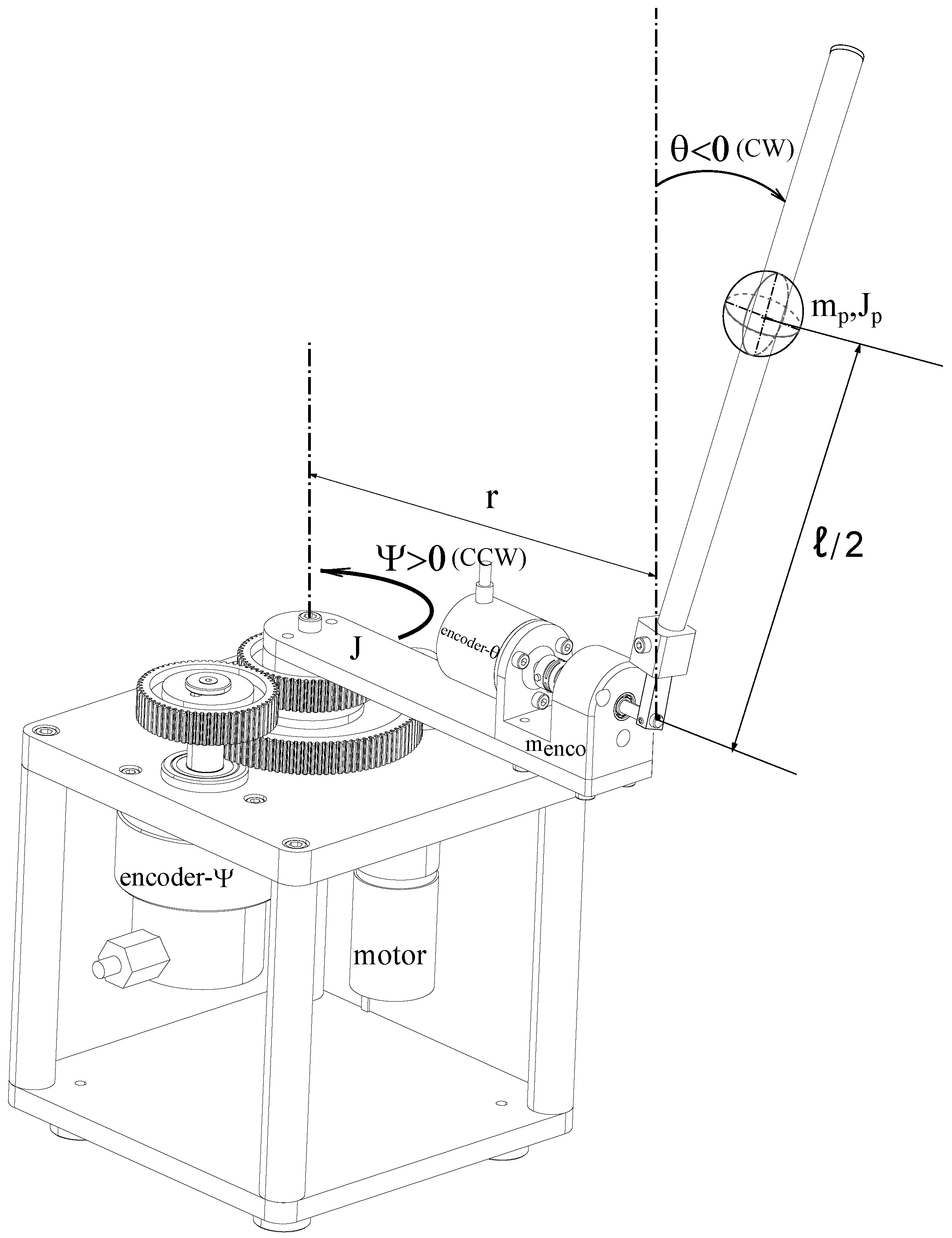
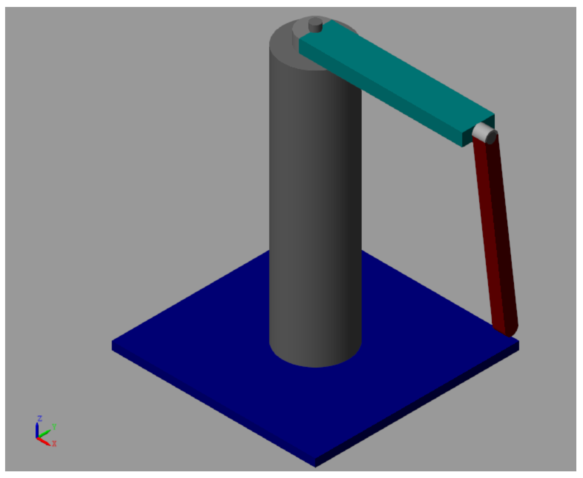
The rotary inverted pendulum model derived from the actual implemented hardware is shown in
Figure 1. The arm has a length
r, a moment of inertia
J about the instantaneous center of rotation and its angle of rotation, and
increases positively when the arm rotates counter-clockwise (CCW). The pendulum rod is connected to the end of the rotary arm. It has a total length
ℓ uniform density; thus, its center of mass is
. The moment of inertia about this center of mass is
. Here, it is assumed that the inverted pendulum angle is zero when it is perfectly upright in the vertical position.
Using classical analytical mechanics, and based on the corresponding sketch of the Furuta Pendulum experimental setup—which explicitly defines the aforementioned geometric parameters and inertial properties of its dynamic components—the equations of motion can be derived through the Lagrange formalism. By applying this method to the system described in the
Figure 1, the dynamic behavior is expressed by the two linearized equations as follows:
with initial conditions:
Figure 1 illustrate the mechanical structure of the Furuta Pendulum and the corresponding multibody model will be developed in detail in
Section 2.3, while
Table 1 summarizes the key inertial properties of its components extracted from the CAD design.
Following traditional control approaches, the primary objective at this stage is to derive the state–space representation of the system in the form
. To achieve this, the nonlinear equations of motion given in (
1) and (
2) are reformulated accordingly. As a preliminary step, the following state variables are defined:
This transformation enables the use of modern control strategies such as lead-lag, Linear Quadratic Regulator (LQR) or state vector feedback techniques; all of them rely on the linearization of the system dynamics around the upright equilibrium to design the control law. By substituting these state variables into the system dynamics, the linearized equations of motion can be expressed in compact matrix form as follows:
where
The parameters
,
ℓ, and
are described in
Table 1. In order to make the matrix expressions more compact, a dynamic reduction has been applied to the inertial properties of the pendulum, simplifying the corresponding terms in the model without compromising its essential dynamics. Thus, the state–space matrices
and
can be derived from the matrices
,
, and
as follows:
By substituting the parameters listed in
Table 1 into the symbolic state–space matrices A and B, and applying a few reasonable simplifications—such as assuming negligible small damping coefficients
and
—one obtains the following numerical approximations for these matrices:
Thus, the poles of the linearized system matrix
are given by:
The resulting pole configuration of the linearized Furuta pendulum system reveals important insights into its intrinsic dynamics. The two poles located at the origin indicate the presence of two pure integrators, commonly associated with the rotational dynamics of the base arm, which lacks inherent stiffness or damping under the assumed simplifications. This behavior corresponds to a marginally stable subsystem. On the other hand, the pair of real and symmetric poles at ±6.8923 characterize the pendulum’s oscillatory mode. In particular, the positive real pole signifies that the system is open-loop unstable and will diverge from the upright equilibrium position unless actively stabilized by external control. Overall, this pole structure highlights the need for feedback control to ensure both stability and trajectory tracking.
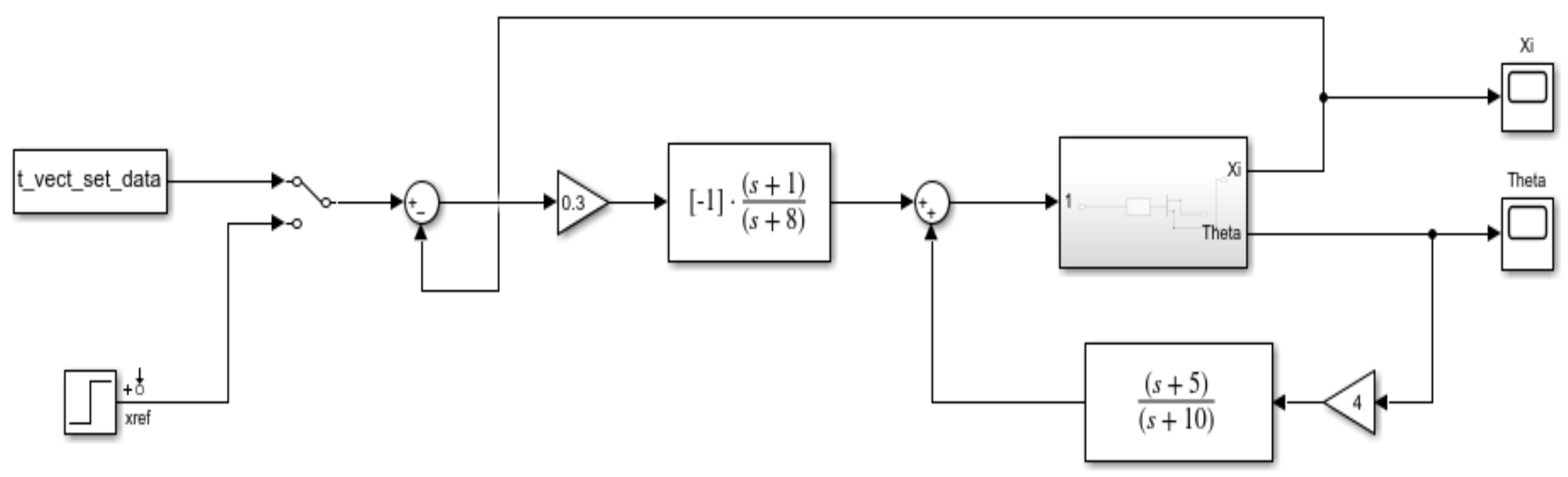
2.2. Cascade Control Design with Lead-Lag Compensators
The control design implemented for the Furuta pendulum relies on a cascade architecture involving two lead-lag compensators: one for the pendulum angle and another for the arm angle . This structure leverages the separation of dynamics between the fast inner loop (pendulum stabilization) and the slower outer loop (arm positioning).
The inner loop compensator is designed to stabilize the pendulum around the upright position by applying a lead-lag controller of the form:
This controller is placed in a feedback configuration with the plant, producing an augmented system denoted as . The scaling factor 4 is introduced to tune the bandwidth of the inner loop relative to the outer one.
The outer loop then applies another lead-lag controller to regulate the arm trajectory based on the reference input
. The compensator is given by:
The total control signal is the result of the cascade of both compensators, forming a two-degree-of-freedom (2-DOF) architecture where the output of the outer loop controller serves as the reference for the inner loop shown in
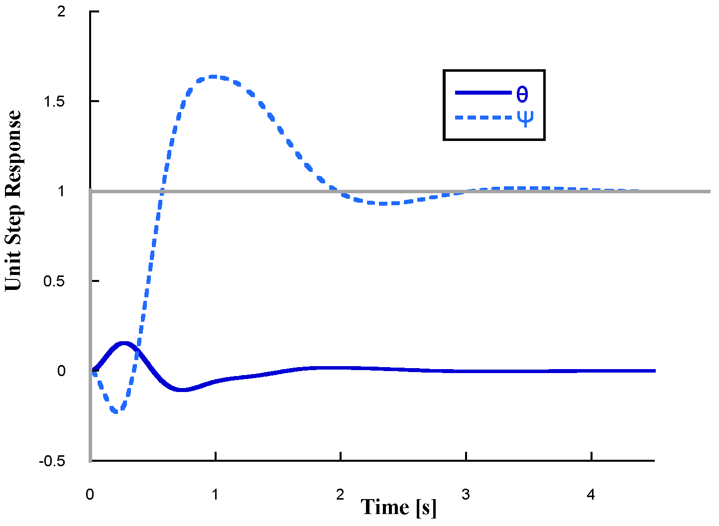
Figure 2. Also
Figure 3 shows the unit step response applied to the reference signal of the rotary arm angle
. The system successfully maintains the pendulum angle
close to the upright position through the hybrid lead-lag control strategy. Part of the previous analysis has been extracted from reference [
23,
24]. For a more in-depth and detailed analysis of the synthesis of these lead-lag controllers, the reader is referred to the same source.
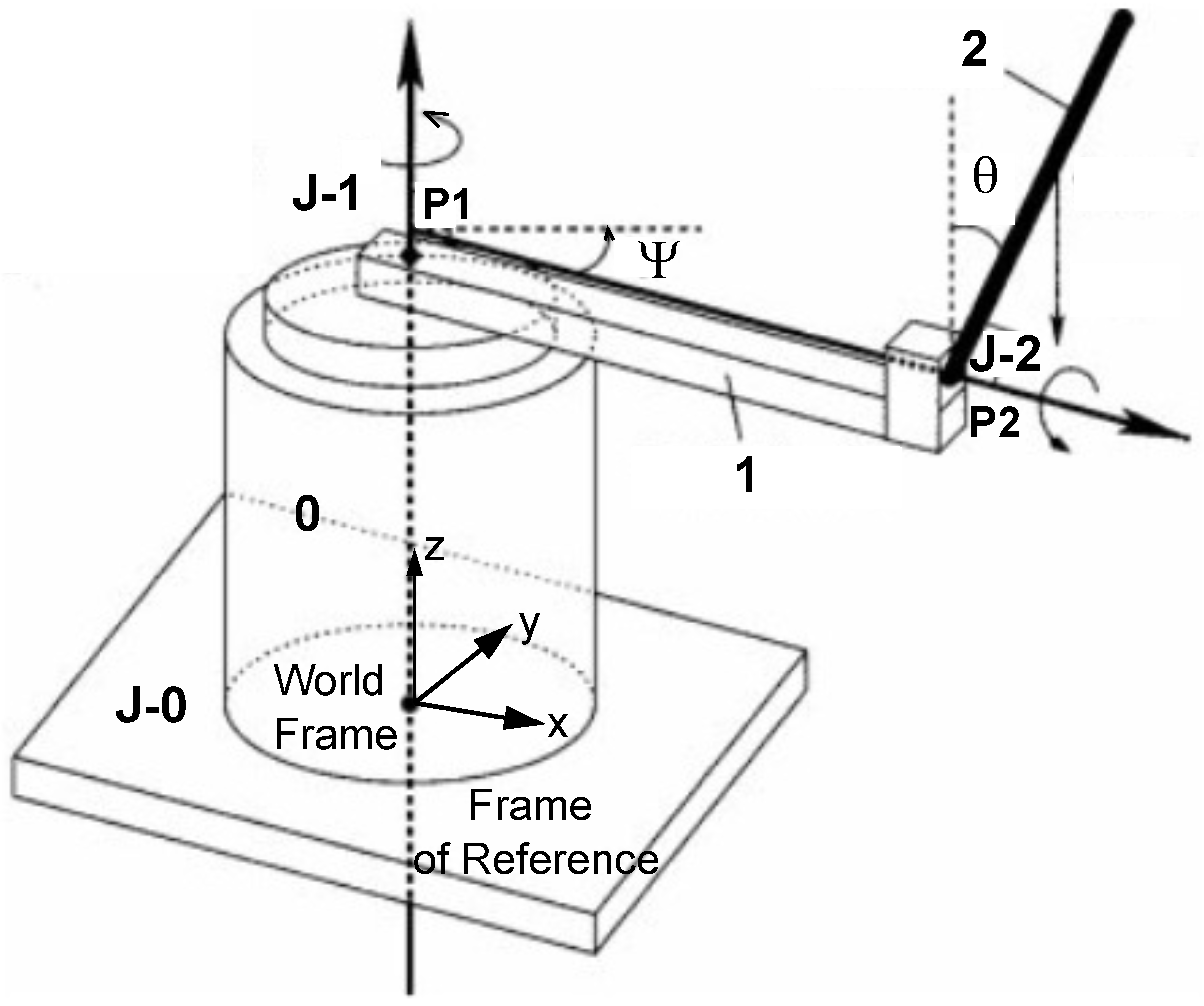
2.3. Multibody Model Formulation
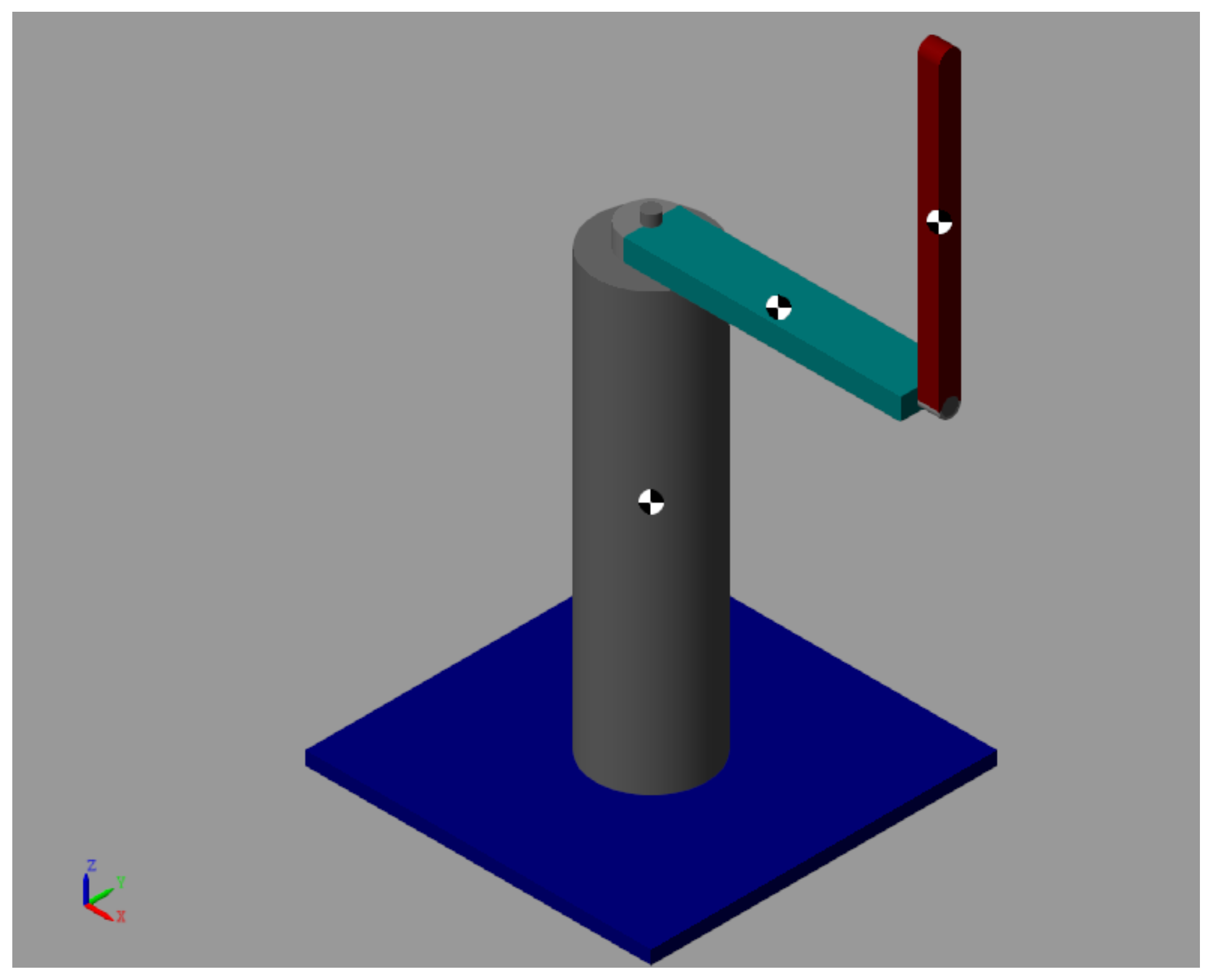
The
Figure 4 depicts the multibody model of the FP mechanical system. It consists of three main rigid bodies:
Frame (Body 0)
Arm (Body 1)
Pendulum rod (Body 2)
The revolute joint J − 1 defines the vertical axis about which the rotary arm rotates within the horizontal plane, with its pivot point located at . The arm possesses a moment of inertia J relative to this axis. The pendulum, modeled as a rigid rod of mass and length ℓ, is mounted at the arm’s free end via the horizontal revolute joint J − 2 at point . It swings in the vertical plane and exhibits a moment of inertia with respect to its center of mass. Briefly, the bodies are connected through two revolute joints:
Joint J − 1: A revolute joint between Body 0 and Body 1, which allows horizontal rotation of the arm in the plane of the base.
Joint J − 2: A revolute joint between Body 1 and Body 2, which enables vertical rotation of the pendulum rod relative to the arm.
Figure 4.
Multibody model sketch of the Furuta Pendulum showing the bodies and kinematic joints.
Figure 4.
Multibody model sketch of the Furuta Pendulum showing the bodies and kinematic joints.
Figure 5 depicts this multibody model translated to Simscape-Multiboy Matlab. Again, the system is composed of three main rigid bodies connected by two revolute joints: the vertical base and arm connection, and the horizontal joint linking the pendulum rod to the arm.
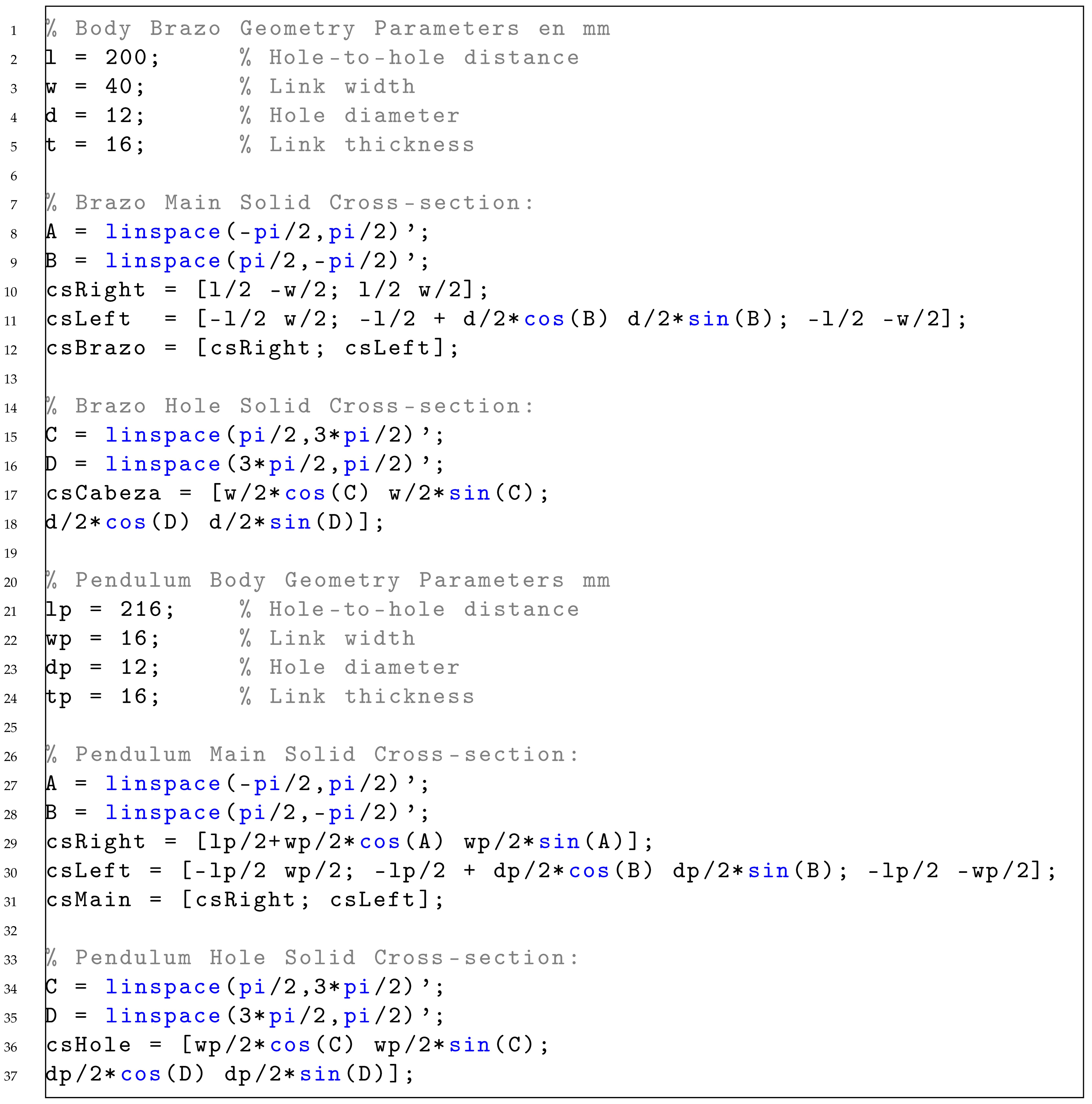
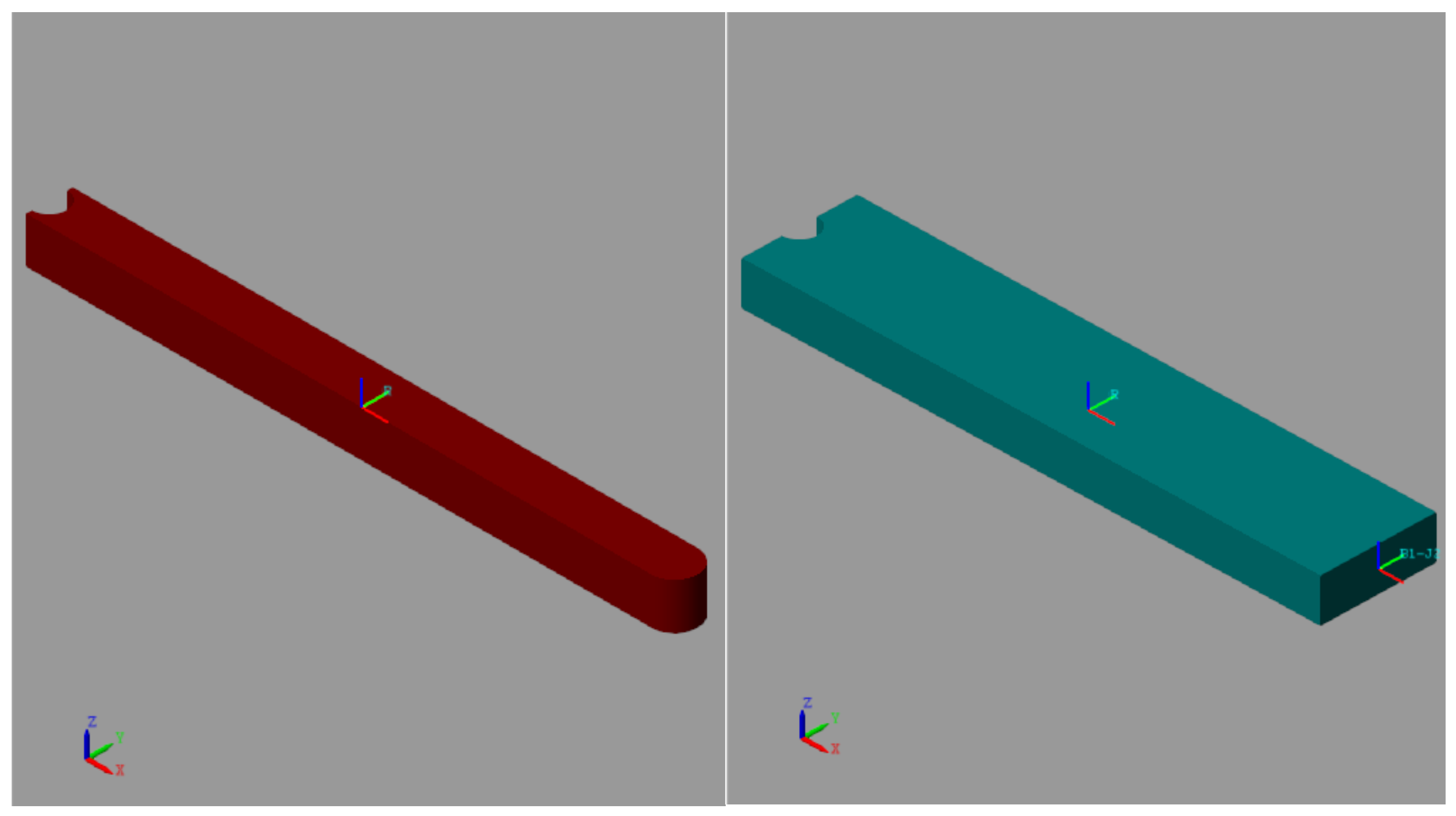
2.3.1. Extruded Solids
To build the multibody model of the Furuta pendulum with enhanced physical fidelity, we used extruded solids defined from 2D cross-sectional profiles, analytically described in MATLAB and imported into Simscape Multibody. This modeling approach allows for an accurate geometric description and enables automatic computation of mass and inertia properties based on the assigned material density.
The two main dynamic bodies—the arm and the pendulum rod—were modeled as extruded solids. Their geometric and inertial parameters are summarized in
Table 2, and the resulting 3D representations are shown in
Figure 6. The precise cross-sectional contours used to define these extrusions are specified in the MATLAB code provided in
Appendix A, which enables reproducibility of the model geometry and ensures consistent inertial property computation. The base is fixed and not involved in the system’s dynamics.
Special care was taken to match the simulated properties to the real hardware: for instance, the arm’s computed mass of 0.1679 kg closely approximates the physical arm’s 0.1866 kg. This adjustment, achieved by tuning the material density, ensures the accuracy of the simulated dynamics, which is essential for validating the nonlinear control strategy.
While the mass of the arm was successfully matched through density adjustment, accurately replicating the moment of inertia is more challenging. When combining the inertia of the extruded arm with the mass contributions of the peg and the head of the pendulum (which together form the revolute joint J − 2 at the distal end of the arm), and applying the parallel axis theorem, the resulting value from
Table 2 is:
This is lower than the approximate theoretical value moment of inertia of the actual mechanical hardware, which is , but remains within an acceptable range for control validation purposes.
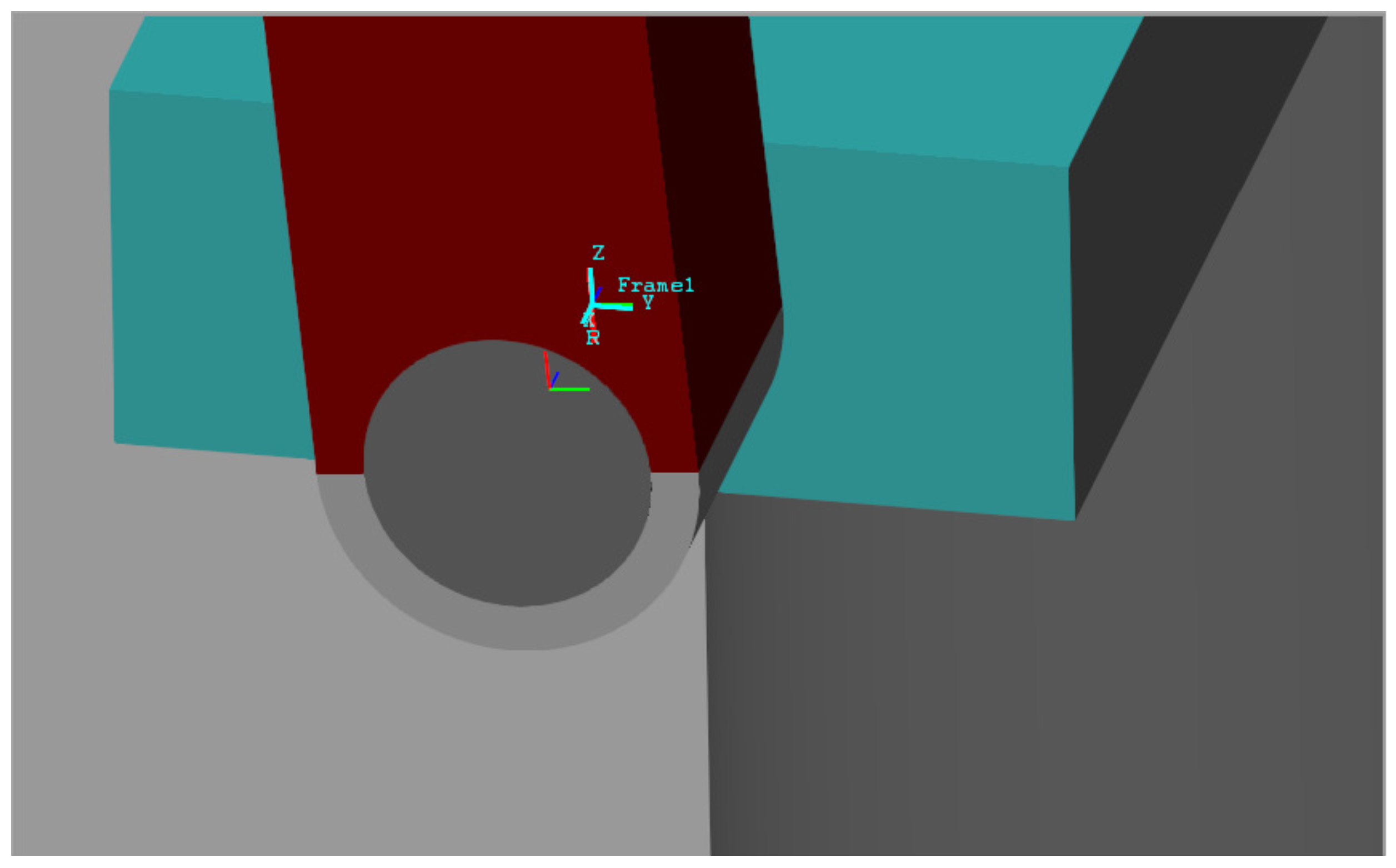
2.3.2. Customized Rigid Transforms and Joints
All rigid bodies were connected using peg-based revolute joints, which replicate the physical constraints of the hardware. Rigid transforms were used to position and orient the two revolute joints in accordance with the axes of the respectived connected bodies. It is important to recall that, in
Simscape Multibody, revolute joints always rotate about the local Z-axis. This default convention is consistent with the configuration of the first revolute joint, which connects the static base (Body 0), rigidly welded to the world frame, to the rotating arm (Body 1). In addition to the mass center frame R of the base (modeled as a cylinder), two additional frames were defined: one on the lower face and another on the upper face of the cylindrical base. The latter is aligned with the peg’s mass center frame and is connected to it through a rigid transform consisting of a translation along the cylinder’s axis, with a value equal to half the customized peg length. This transformation is essential to correctly define the weld joint between the base and the peg of the first revolute joint (Joint J1). Furthermore, the frame attached to the center of mass of the peg acts as the base of Revolute Joint J − 1, while the follower frame is rigidly attached to the geometric center of the extruded solid that forms the arm’s head. This head consists of a 180-degree semicircular arc, as detailed in the MATLAB script provided in
Appendix A.
The cylindrical peg used to connect the pendulum to the arm has its axial Z-axis aligned with the longitudinal X-axis of the arm through a custom rigid transform. This alignment is achieved by pairing two axis directions as described in
Table 3 and
Figure 7, ensuring a consistent orientation for the revolute joint J − 2. No translational offset is applied in this transformation, as the peg is placed in direct contact with the tip of the arm. Regarding this revolute joint J − 2, the only reference frame defined in the peg (embedded at its center of mass) serves as the base of the joint. The follower frame is located at the geometric center of the semicircular head of the pendulum, modeled as an extruded solid. To properly connect the follower port of J − 2 to the head, two consecutive rigid transforms are applied. The first is a rotation of –180 degrees around the Y-axis of the head’s frame, allowing it to wrap around the horizontal peg. The second is a translation along the Z-axis to achieve precise alignment between the two frames. These transformations are detailed in
Table 4 and
Figure 7.
2.3.3. Sensor Configuration for Angular Measurements
Only the angular sensors for and remain to be specified in the model. The angular position is directly obtained by enabling the position-sensing option within the settings tab of the Revolute Joint J − 1. This internal sensor provides the relative rotation angle of the joint around its axis, which corresponds to the horizontal rotation of the arm . As for the pendulum angle , it is measured by a dedicated Transform Sensor block placed between the world frame and the pendulum body frame. This block is configured to output the rotation angle around the reference world axis Z, allowing precise tracking of the pendulum’s oscillation in the vertical plane. It should be noted that, when using this transformation sensor, the measured value of the angle is when the pendulum is in the upright (vertical) position. Thus, the actual used for control purposes is computed as minus the angle measured by the transformation sensor, ensuring that the control reference is zero when the pendulum is in the upright position.
2.3.4. Multibody Model Validation
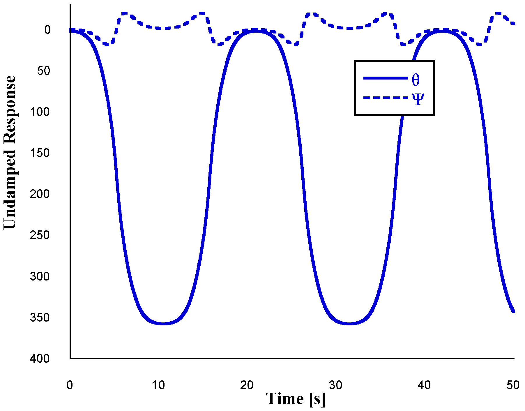
Figure 8 illustrates the undamped free-fall response of both the pendulum and the rotating arm, as computed from the multibody model implemented in Simscape. In this simulation, the pendulum is initially released from a small angular deviation of
from the upright position. As expected, the pendulum exhibits periodic oscillations due to the restoring gravitational torque. Additionally, the arm undergoes oscillations induced by the inertial coupling with the pendulum, despite the absence of any active input torque in the absence of damping effects. This coupled response highlights the intrinsic dynamic interaction between the two degrees of freedom and provides a basis for identifying natural frequencies and validating the model structure. To estimate the natural frequency of the oscillation of the set arm-pendulum, a Fourier Transform analysis is conducted. The single-sided amplitude spectrum of
is presented in
Figure 9, from which the dominant frequency component is identified as approximately
.
At this point, in order to validate the inertia properties of the pendulum itself, a free-fall simulation is performed again under the assumption of negligible damping in the pendulum and strong damping at the revolute joint J − 1 of the arm. This configuration effectively suppresses the rotational motion of the arm shown in
Figure 10, allowing the isolation of the free vibration response of the pendulum. If this is the case, the pendulum is released from rest with an initial angular deviation of
from the downward vertical equilibrium position, assuming small-angle dynamics around this configuration.The resulting angular response
in the time domain is later used to estimate the natural frequency and validate the moment of inertia of the pendulum.
Assuming small angular displacements and neglecting damping, the theoretical natural frequency
of a physical pendulum is given by the following expression:
where
denotes the position of the center of mass of the pendulum bar (a uniform rod),
is the total mass of the pendulum, and
is the moment of inertia of the pendulum with respect to the pivot point (revolute joint J − 2). The experimentally identified frequency, in this case of approximately 1.30 [Hz] as demonstrated in
Figure 11, can thus be used to compute or cross-validate the moment of inertia
and compare it to the value obtained in the multibody model using the parallel axis theorem as follows:
As stated before, to further validate the multibody model, a numerical estimation of the pendulum’s moment of inertia was performed based on the measured natural frequency from the undamped free oscillation response. Using the expression
and the measured frequency
Hz, the corresponding moment of inertia about the pivot point (revolute joint J − 2) is computed as
Applying the parallel axis theorem yields the moment of inertia about the center of mass:
A small-amplitude oscillation test was performed to identify the natural frequency of the pendulum, yielding a value of approximately
, as demonstrated in
Figure 11, where the FFT of the angular displacement
was processed. Based on this frequency, the moment of inertia of the pendulum about its center of mass was estimated to be
carried out in Equation (
13). Remarkably, this experimentally inferred value is in very close agreement with the moment of inertia
computed internally by
Simscape Multibody for the extruded solid representing the pendulum body, which reports
as depicted in
Table 2. Furthermore, both values align with the theoretical expression given in
Table 1 for a uniform rod,
, thereby reinforcing the physical fidelity and reliability of the multibody model.
2.4. Multibody-Based Control of the Furuta Pendulum
Although a thorough analysis and comparison of the wide range of possible control strategies for the Furuta Pendulum exceeds the scope of this article, the present section aims to showcase the capabilities of the proposed multibody-based framework as a flexible platform for the design, implementation, and validation of hybrid control systems. By integrating classical control elements such as proportional, PI, and lead-lag compensators with nonlinear control features like impulse modulation and reset logic, this framework allows for intuitive tuning, rapid prototyping, and direct evaluation of control performance on a realistic nonlinear model.
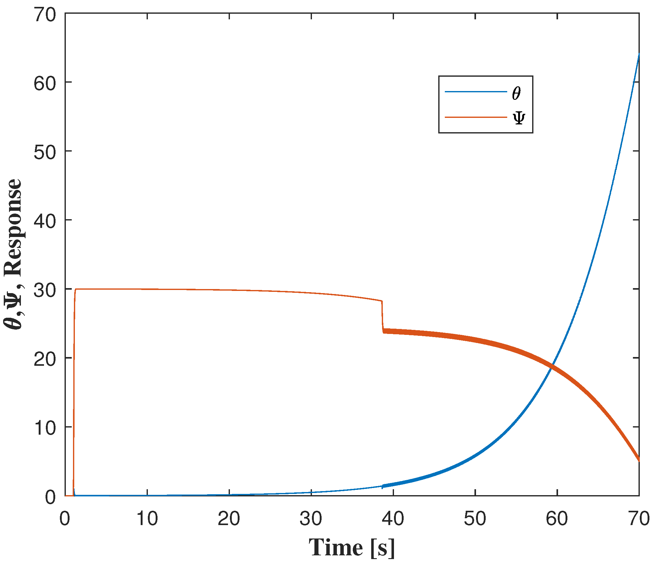
Figure 12 shows the response of the multibody Furuta Pendulum model to a
step input applied to the rotary arm angle
. The implemented control strategy includes a proportional controller for the arm, a lead-lag compensator for the pendulum angle
, a PI controller with reset logic, and a modulated impulse generator that is activated when the pendulum deviates more than
from the upright position. Despite the combined action of these controllers, the pendulum eventually loses balance and falls after approximately 40 s. This behavior highlights both the limitations of conventional control under severe nonlinearities and the potential of the multibody framework for testing and refining hybrid control approaches.
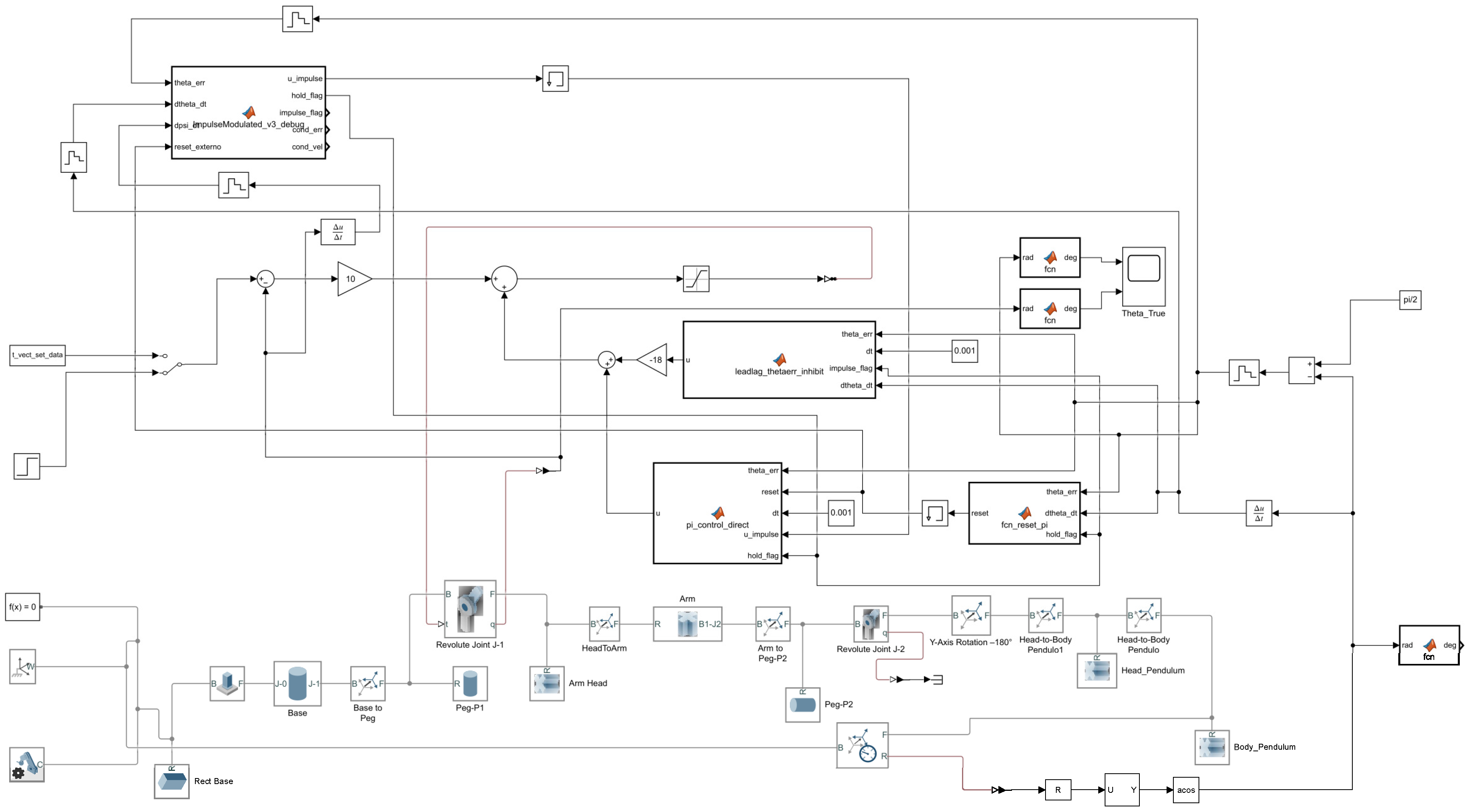
Figure 13 illustrates the complete nonlinear control architecture implemented in Simulink for the multibody Furuta pendulum model. As stated above, the control system integrates a lead-lag compensator, a PI controller with reset logic, and a modulated impulse generator, coordinated through condition-based logic for hybrid switching. The diagram also shows the interaction between the control components and the multibody subsystem, highlighting the effort to combine classical and nonlinear control techniques within a realistic simulation environment. This configuration enables advanced tuning and testing of hybrid strategies under high-fidelity dynamic behavior.
3. Results
The results presented in this section focus on the construction and validation of the multibody model developed for the Furuta Pendulum using the
Simscape Multibody environment in MATLAB. This model was built from first principles using extruded solids and rigid transforms to accurately replicate the geometric and inertial properties of the physical system shown in
Figure 14. The rotary arm and the pendulum rod were modeled as extruded solids, defined from analytically programmed 2D profiles. Their mass and inertia properties were automatically computed based on the assigned material densities. Additional geometric components—such as cylindrical pegs and semicircular heads—were incorporated to set up the revolute joints J − 1 and J − 2 with physically consistent placement.
Table 1 and
Table 2 summarize the mass and inertia properties of each body, both for the approximate theoretical values extracted from CAD design corresponding to the actual mechanical hardware, and for their counterparts in the multibody model developed using the
Simscape Multibody environment in MATLAB.
The correct positioning and orientation of each body was ensured through a structured series of rigid transformations. These transforms aligned the axes of the revolute joints with the appropriate local frames, respecting the requirement that
Simscape Multibody revolute joints always rotate about the Z-axis. The frame configuration for both joints is documented in
Table 3 and
Table 4, and illustrated in
Figure 5,
Figure 6 and
Figure 7.
To validate the fidelity of the multibody model, a series of open-loop simulations were carried out. In these, a step input was applied to the rotary arm without any stabilization control on the pendulum. The resulting dynamic response—particularly the free oscillations of the pendulum about the vertical—was recorded and analyzed. As shown in
Figure 10, the pendulum exhibits a characteristic natural oscillation when slightly perturbed from the downward equilibrium.
A Fourier analysis was then performed on the
time signal to extract the dominant frequency of the pendulum motion. This experimentally observed frequency was compared with the theoretical natural frequency computed from the simplified linearized dynamics:
where
is the distance from the joint to the pendulum’s center of mass and
is its moment of inertia about the pivot axis. The close match between the dominant frequency extracted from the simulated free response and that predicted by the analytical model provides strong evidence of the multibody representation’s fidelity in capturing the system’s inertial properties and dynamic coupling.
These results validate the multibody model as a reliable platform for future control design and benchmarking studies, where physical realism and geometric fidelity are critical. Moreover, the results highlight two essential conclusions. First, they illustrate the limitations of conventional control approaches under strong nonlinear dynamics. Second, and more importantly, they demonstrate the value of the multibody framework in allowing systematic design, tuning, and validation of hybrid and nonlinear control schemes, providing a realistic and intuitive environment for controller development prior to experimental deployment.
Beyond the validation of the multibody model’s inertial accuracy, an important set of simulations was conducted to evaluate the performance of classical controllers when applied to the nonlinear multibody system. Specifically, a cascade control strategy consisting of a proportional controller for the rotary arm and a lead-lag compensator for the pendulum angle was tested under a step reference applied to the arm position .
While initial results showed that the pendulum remained stabilized near the upright position, further simulations revealed that, after several seconds of motion and increased rotational displacement of the arm, the pendulum eventually lost balance and fell. This outcome occurred despite the inclusion of hybrid control features such as a PI controller with reset logic and a modulated impulse generator triggered when deviated more than from vertical.
These results demonstrate a critical insight: classical control laws that perform well on simplified, linearized models may be insufficient when deployed on systems exhibiting strong nonlinearities and dynamic coupling. The multibody simulation environment allows these subtle yet significant effects to emerge, serving as a reliable benchmarking tool to identify control vulnerabilities and guide the development of more robust hybrid strategies.
4. Discussion
The results presented in this study demonstrate the feasibility of using a multibody model developed in
Simscape Multibody as a flexible and physically grounded framework for the design and analysis of hybrid control strategies applied to the Furuta pendulum. Unlike conventional approaches such as LQR [
8], Lyapunov-based designs [
1], or terminal sliding mode control [
9], which are developed on simplified or linearized dynamic models, the proposed methodology enables control design and tuning directly on a high-fidelity nonlinear digital twin. This allows for the incorporation of structural nonlinearities, joint behavior, and dynamic coupling, as well as more intuitive visualization of controller performance under realistic conditions.
Compared to the model predictive control strategies proposed in [
7], or reset-based schemes like those in [
15], our implementation combines classical lead-lag and PI controllers with hybrid elements such as impulse modulation and reset logic. However, unlike [
7], we do not require full state estimation or online optimization, which simplifies real-time deployment but also limits adaptability to strong disturbances or sustained energy injection. Nonetheless, in contrast to the robust nonlinear techniques of [
9], the control architecture in this work was manually tuned and lacks formal robustness guarantees.
Despite these advantages, the current hybrid control architecture—combining a proportional controller for the rotary arm, a lead-lag compensator plus a PI with reset controller for the pendulum, and a modulated impulse generator, was not fully sufficient to prevent the pendulum from falling after approximately 40 s. This highlights the inherent difficulty of stabilizing such an underactuated and nonlinear system, especially when relying on heuristically tuned hybrid controllers.
Nevertheless, a key contribution of this work is the demonstration that controllers designed for the linearized model may show promising short-term performance, but eventually degrade when tested on the nonlinear multibody counterpart. This performance drop—clearly observed in the simulations—is rarely discussed in the literature, where most control designs are tested on idealized or partial models only. Our results thus reinforce the value of the proposed multibody-based benchmarking approach as a tool for revealing control limitations and guiding the development of more robust, structure-aware strategies.
Limitations: While the multibody model provides a realistic simulation environment, it assumes rigid body dynamics and does not yet incorporate sensor noise, actuator delay, or frictional backlash. Moreover, the current control architecture lacks automatic adaptation or optimization mechanisms. Finally, experimental validation on the physical prototype, although planned, is still in progress.
5. Conclusions
This work has presented a multibody-based modeling and benchmarking framework for the Furuta pendulum, developed in the Simscape Multibody environment. Unlike conventional approaches based on linearized dynamics, the proposed digital twin captures the full nonlinear behavior of the physical system, including geometric and inertial features, and enables direct integration with hybrid control schemes.
The framework was used to evaluate the performance of a classical cascade controller augmented with PI reset logic and impulse modulation. Simulation results showed that, while initially effective, this control architecture fails to ensure long-term stabilization when tested on the nonlinear model. These findings underscore the importance of realistic simulation platforms for control validation.
Future work will focus on deploying the developed controllers on the actual hardware and exploring more advanced nonlinear control strategies—such as model predictive, adaptive, or robust sliding mode control—directly within the proposed multibody framework.
Future Work
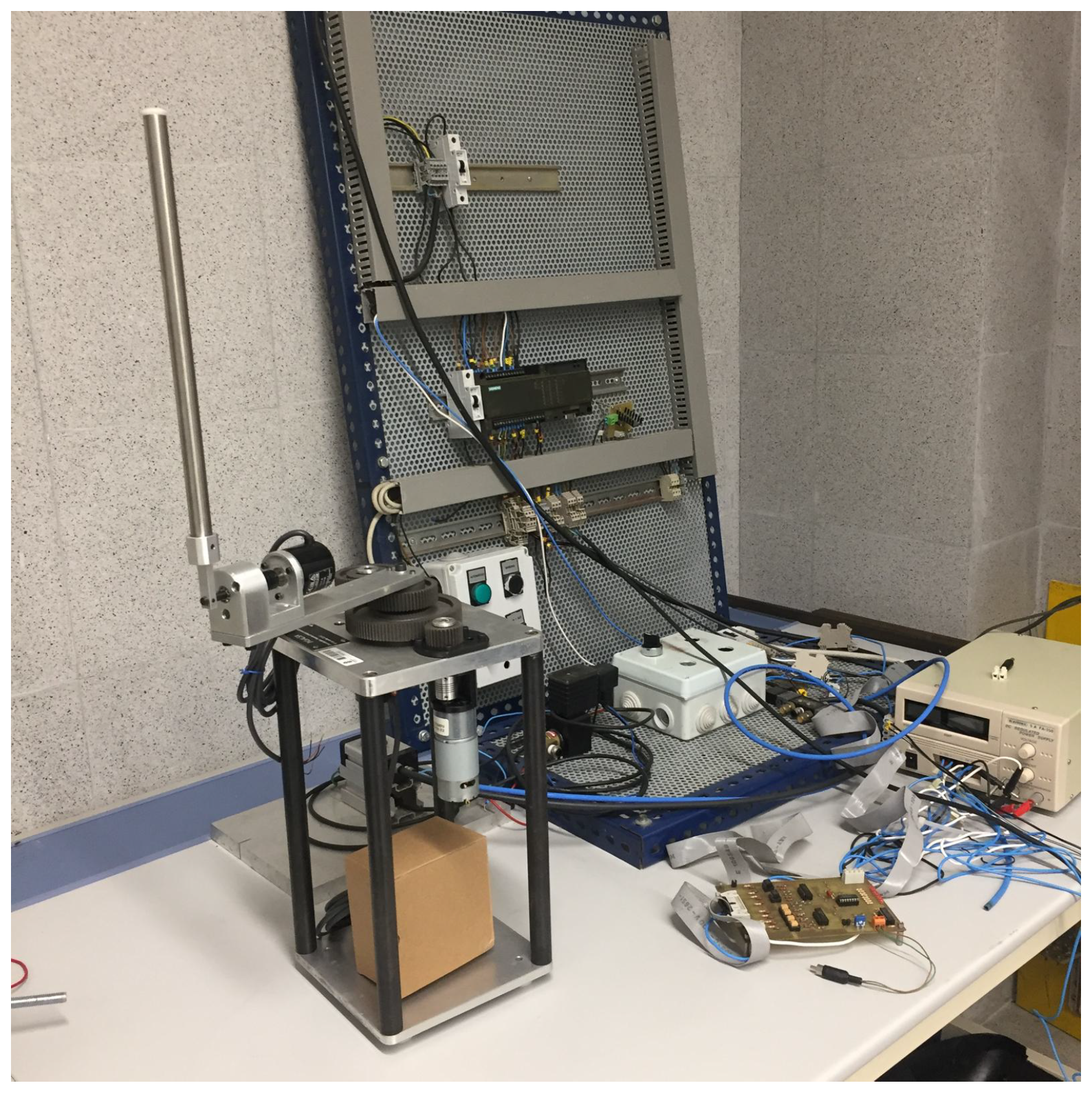
The question of whether control strategies tuned or designed using the multibody model can be successfully implemented in real hardware remains open. To this end, the authors plan to deploy the developed control scheme on the actual Furuta pendulum hardware, shown in
Figure 14. The geometric design of the rotary arm and pendulum rod in the multibody model was extracted directly from the CAD model of this physical system, ensuring consistency between simulation and implementation.
The proposed control will be implemented on a Siemens S7-1214 programmable logic controller (PLC) using the capabilities offered by the TIA Portal environment. Both rotational joints are equipped with incremental encoders, whose quadrature signals (phases A and B) will be processed using high-speed inputs available on the PLC. TIA Portal also provides software blocks for real-time angle estimation and supports the SCL programming language, which is well suited for implementing control algorithms related to the dynamics of multibody systems.The actuator is a DC motor whose velocity is regulated via PWM (Pulse Width Modulation), using a power stage based on an H-bridge configuration, such as the L298 driver.
As a complementary embedded approach, future work will also consider implementing the control strategy on a high-performance STM32H743ZI2 microcontroller, which is fully supported by MATLAB/Simulink for automatic code generation and real-time deployment. This alternative has already been explored in recent work on embedded model control for underactuated systems, such as the Furuta pendulum [
25], and offers the advantages of portability, speed, and flexibility in field applications. Moreover, the potential of combining input-shaping techniques with embedded adaptive control has recently been demonstrated in [
26], where a model reference adaptive controller augmented with input shaping was successfully implemented for a flexible single-link manipulator. These findings support the feasibility of embedding advanced vibration suppression methods into real-time control architectures, and motivate their future application to the Furuta platform.
In addition, future work will focus on exploring more advanced nonlinear control strategies—such as model predictive, adaptive, or robust sliding mode control—directly within the proposed multibody framework.


