1. Introduction
The progression of nanotechnology continues to drive demand for increasingly precise and scalable positioning systems. In fields such as semiconductor manufacturing, nano-optics, and high-precision metrology, there exists an increasing demand for positioning systems capable to reach the single-digit nanometer precision [
1,
2]. Within this context, recent advances in nanoscience have enabled the nanotechnology field to operate at the sub-10 nm scale [
3,
4]. These advances in nanoscience require robust nanopositioning systems that combine ultra-high precision with fully actuated degrees of freedom (DOFs), in addition to offering reconfigurable and scalable operation depending on the task demands.
A significant contribution to nanotechnology is the development of integrated nanopositioning platforms that enable motion in all six DOFs—three translations (
x,
y,
z) and three rotations about the corresponding axes (
,
,
)—within a unified system architecture. The motion platform originally introduced as the NPPS100-6D [
5,
6], now referred to as the NPS6D100, represents a compact and scalable solution for 6D multicoordinate nanopositioning. The NPS6D100 constitutes a well-suited nanopositioning platform for sub-10
applications in nanoscience and sub-10
precision metrology. The system is highly relevant for medical applications that require precision nanopositioning during micro-surgical procedures [
7,
8]. The nanopositioner architecture integrates a planar direct drive for horizontal motion in
x,
y, and
, upgraded with three lifting and actuating units (LAUs) for vertical displacement in
z and angular rotations about
and
. Each LAU has a parallel arrangement combining a low-dynamic pneumatic actuator for weight force compensation and a high-dynamic voice-coil drive for precision motion; see [
9,
10]. In addition, the integration of a suitable guiding system provides virtually frictionless planar and vertical motion.
The pursuit of sub-10 nm precision has led to the development of integrated nanopositioning solutions. These approaches permit nanometer positioning across long ranges while maintaining robustness and high-precision performance. While many works target small travel ranges [
11,
12,
13], this paper addresses long-range stages (≥50 mm × 50 mm in the
plane) that maintain nanometer-level servo errors through careful stage architecture and precision engineering principles [
14,
15,
16]. Various concepts exist in the literature, often using parallel kinematics with Lorentz actuators and roller or air bearings, as seen in the NanoCMM [
17], and the high-precision 3D CMM [
18]. Integrated direct-drive architectures [
6,
19], combined with air bearing guidance, show particular promise. At TU Ilmenau, the long-range NPMM-200 [
20]—evolved from earlier stacked designs [
21,
22]—has demonstrated excellent 3D measurement capabilities [
23,
24]. The NFM-100 system [
25,
26] offers planar positioning over a Ø
. A similar platform, the NPP-1 [
27], is commercially available from SIOS GmbH. Furthermore, initial investigation on the NPPS100-6D [
5] extends the planar direct-drive concepts to include vertical actuation with long travel ranges of Ø
. The most significant exemplar is the NPS6D200 [
28,
29] that combines a 3D planar direct drive with vertical actuation featuring a long working range of Ø
with high-precision 6D closed-loop control and single-digit nanometer precision [
30]. A comparative table to supplement the distinction between similar nanopositioners in the literature is shown in
Table 1. In summary, we recognize the potential of the direct drive principle on the one hand, and the need to integrate vertical adjustment on the other hand. A combination of both without the necessity for coil lift integration closes the gap between the existing solutions and allows the investigation of the characteristics, the benefits, and the limitations of such motion stage architectures.
The main difference from its larger counterpart—the NPS6D200—is that the NPS6D100 does not include a coil lift system. This results in a simpler and lighter construction with enhanced stiffness in the actuation chain and lower disturbance generation, while still maintaining full 6D actuation. The NPS6D100 features a long-range working volume—Ø
—with high-precision 6D closed-loop control and sub-
precision. The absence of the coil lift system, combined with the compact dimensions of the nanopositioner, enables improved positioning fidelity in nanofabrication and nanomeasurement applications. The NPS6D100 presents a metrology setup different from the NPS6D200 [
28,
29], which consists of three orthogonally arranged laser interferometers (LIFs). This Cartesian metrology configuration is particularly advantageous for tasks requiring direct alignment with the moving axes, ensuring direct positioning measurement, whereas the alignment follows the Abbe comparator principle [
16]. In the broader context of nanopositioning systems, the NPS6D100 represents a versatile platform for applications that demand deterministic motion control and multi-axis stability over medium to long travel ranges. Its open architecture allows for easy integration with probing systems, optical sensors, or surface interaction tools, extending its applicability to nano-inspection, nanofabrication, and metrology instrumentation. This paper provides an overview of the NPS6D100, presenting its mechanical architecture, actuation principles, control system, and performance outcomes. The focus is placed on six-dimensional precise positioning within a long-range working volume, suitable for high-precision research and industrial applications.
This paper is organized in five sections. Following the introduction,
Section 2 introduces the NPS6D100 and its overall design, covering the planar drive system, vertical actuation, and guiding mechanism.
Section 3 presents the motion controller design.
Section 4 evaluates the positioning performance achieved across various motion tasks.
Section 5 closes this paper with conclusions and the outlook for future work.
2. Description of the Nanopositioning System
The NPS6D100 comprises a 6-DOF nanopositioning system designed to achieve sub-
performance within a cylindrical workspace of Ø
. The NPS6D100 builds on its predecessor—the NPPS100 platform [
6,
19]—by incorporating vertical lifting and tilting motion, extending its functionality toward full 6D actuation. The system architecture combines a planar electromagnetic direct drive with three lifting modules (or LAUs), enabling precise motion in
x,
y,
z,
,
, and
. The following subsections describe the mechanical structure, planar drive system, and vertical actuation.
2.1. System Description
The NPS6D100 consists of two main elements, i.e., the slider, which includes all the moving components, and the stator, which comprises all the frame-fixed parts [
5]. The slider comprises a triangular monolithic Zerodur platform, providing extremely low thermal expansion and high stiffness in the actuation chain. Two mirrors are orthogonally aligned and bonded on the top of the slider, while a third mirror is placed on its bottom surface. These mirrors interact with LIFs, from SIOS GmbH, arranged in a Cartesian layout to directly measure displacement along the
x,
y, and
z axes. Angular displacements
and
are measured using a 2D autocollimator directed at the bottom surface of the slider, while
is determined using a dual-beam LIF configuration. The slider is supported on three LAUs, each placed at a corner of the slider. This three-point support forms a parallel kinematic structure that ensures a well-defined mechanical constraint while enabling actuation in all six DOF. Given the implementation of these lifting modules, the vertical working range covers up to
. To achieve control accuracy at the nanometer level, it is vital to reduce the impact of external disturbances. Therefore, the whole system is placed in an 18
basement equipped with passive pneumatic vibration isolation. The system is also located inside an acoustic enclosure to shield it from air currents and acoustic noise in the laboratory. This enclosure also provides thermal decoupling from the laboratory air temperature, thereby stabilizing the thermal environment of the machine. An overview of the nanopositioning system and its components is shown in
Figure 1 and the main mechanical parameters of the NPS6D100 are listed in
Table 2.
The Cartesian configuration of the measurement system implies that each motion axis (
x,
y,
z) is measured independently along orthogonal directions. This setup simplifies the transformation of raw sensor data into stage coordinates and provides minimal coupling between degrees of freedom. For
specifically, the yaw angle is computed directly from the optical path difference between the two parallel beams of the
y-axis LIF, which are laterally offset by
. Note that the motion in
y-direction is measured using only a single beam from the dual-beam
y-axis LIF. The beam paths of the LIFs—considering only a single beam of the
y-axis LIF—intersect at a virtual common point, located near the center of the optical cube formed by the three mirror surfaces, see
Figure 1. This intersection ensures compliance with Abbe’s comparator principle [
16]. The monolithic construction of the slider guarantees that the geometric relationships remain fixed over time. Since all DOFs are directly measured, no further linear transformation is required to compute the spatial position coordinates and orientation.
Table 3 summarizes the resolution of the displacement and angular measurement systems.
A centralized dSPACE control hardware is used for rapid control prototyping and manages signal acquisition and interfacing with the LIFs, 2D autocollimator, linear current amplifiers, pneumatic supply units, and redundant local encoders, among other components, for initialization, shutting down, and fail-safe procedures. All electrical currents and pneumatic pressures are routed from the slider to the stator via structured cables and tube paths to minimize parasitic force disturbances.
2.2. Planar Drive System with Aerostatic Guiding
The planar drive system consists of three Lorentz-force actuators arranged in a
triangular configuration. Each actuator is composed of a pair of planar coils mounted on the stator and a magnet array fixed to the underside of the slider. The permanent magnet arrays are aligned along the edges of the triangular slider, while the corresponding coil pairs are mounted on the granite stator surface. This is illustrated in
Figure 1.
The forces generated by the three electromagnetic actuators are combined to produce arbitrary motion in the
x and
y directions, as well as a rotation
around the
z-axis. The coils are energized through a motor commutation, producing horizontal forces. Each actuator contributes a force
, with
, which is resolved into Cartesian components and combined to produce planar forces in the
x and
y directions, as well as a torque around the
z-axis. The resulting forces are calculated using the linear transformation
where
is the distance from the geometric center of the slider to each Lorentz actuator.
As a result of vertical displacement, the air gap between the magnet array and the planar coils increases as the slider is lifted. However, this effect does not compromise the stability of the motion platform. Experimental data and finite element method (FEM) simulations for similar drives have confirmed that for vertical displacements of up to
, the drive provides adequate propulsion without the implementation of a coil lift system [
5,
28]. This effect of the force constant reduction was evaluated in an experimental identification of the planar drive’s force constant, which revealed that it decreases from
/
at a working height of 1
to
/
at the maximum working height. In the actual system configuration, the maximum peak coil current is 3
, which introduces a working height limit of 7
, up to which the full acceleration of 250
/
is obtainable. Beyond 7
, the permissible acceleration steadily decreases to 200
/
the maximum working height.
To guarantee frictionless motion, the slider is supported on three aerostatic bearing pads, one located beneath each LAU (see
Section 2.3). These pads provide a pressurized air gap of approximately
. The air flows through the surface, generating a stable pressure field. The use of air bearings eliminates mechanical contact, allowing smooth motion and stable dynamic behavior. Therefore, the 3D planar Lorentz-drive together with the aerostatic guidings provide a robust platform for high-precision motion in the
-plane, with almost no friction and hysteresis nonlinearities. To complement the discussion, the reader may consult [
5,
6,
19] and the references therein.
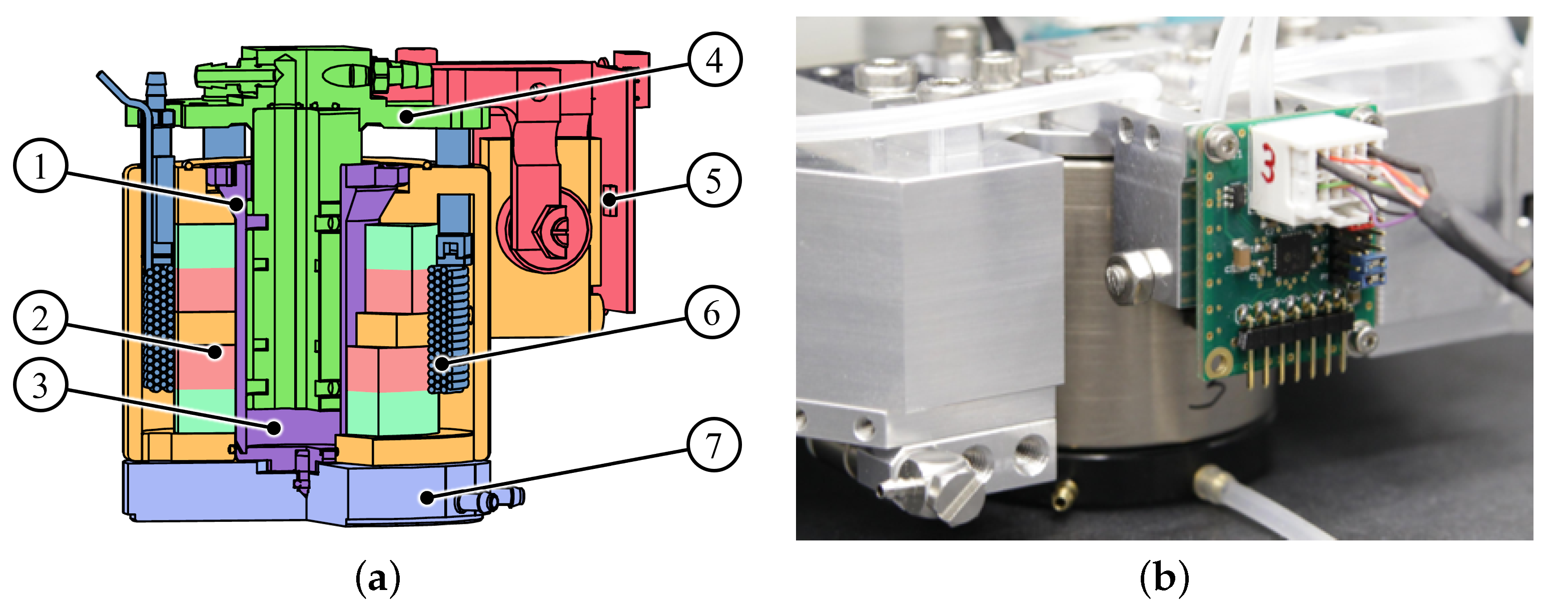
2.3. Vertical Drive System with Aerostatic Guiding and Weight Force Compensation
The vertical displacement (in the
z-axis) and angular rotation (
,
around the
x,
y-axis) of the NPS6D100 are realized through the propulsion of three identical LAUs [
9,
10]. Each lifting module integrates two parallel actuators—a voice coil and a pneumatic piston—with a high-stiffness aerostatic guiding and an auxiliary encoder for local displacement measurement. Each lifting module operates within a travel range of
and generates a force
, with
, which is combined to produce a vertical force in the
z-axis and torques around the
x and
y axes. These forces are computed through the linear transformation
where
is the distance from the geometric center of the slider to each lifting module.
The precise positioning force is generated by a Lorentz-force drive. The voice coil is embedded concentrically within the LAU and generates force via Lorentz interaction between the coil and the radial magnetic field generated by the permanent magnet. The electromagnetic drive is designed to generate dynamic forces and operates at zero average current during stationary conditions. This almost zero current is produced due to the application of a suitable control allocation strategy [
31,
32] and results in minimal heat emission in the measuring space. To reduce nonlinearities, the ferromagnetic material in the lifting module is minimized, resulting in a linear and thermally stable behavior.
The low-dynamic pneumatic actuator counteracts the static vertical load, which includes the weight of the slider and any mounted payload. This integrated subsystem consists of a pneumatic piston with an air pressure chamber featuring contactless sealing to minimize friction and wear. An equilibrium pressure of approximately compensates one-third of the total slider weight per LAU, ensuring that the electromagnetic actuator does not bear big offset forces. To extend the functionality of the NPS6D100, the pneumatic actuator has a working pressure range of up to .
Each LAU features an aerostatic bushing which provides almost frictionless vertical motion and an aerostatic bearing pad mounted on the bottom of the LAU for almost frictionless planar motion. The lifting module additionally includes a dedicated linear optical encoder. This sensor is used for internal measurement during initialization and fail-safe scenarios, where the LIF’s feedback may be temporarily unavailable. The encoder provides vertical measurement with micrometer resolution. The control commands are distributed among the integrated electromagnetic and pneumatic actuators using a control allocation approach that separates the frequency ranges [
32,
33,
34]. In this context, the pneumatic piston manages the low-frequency components, while the Lorentz-force actuator handles the high-frequency dynamics. A cross-sectional view of the LAU is shown in
Figure 2.
3. Control System
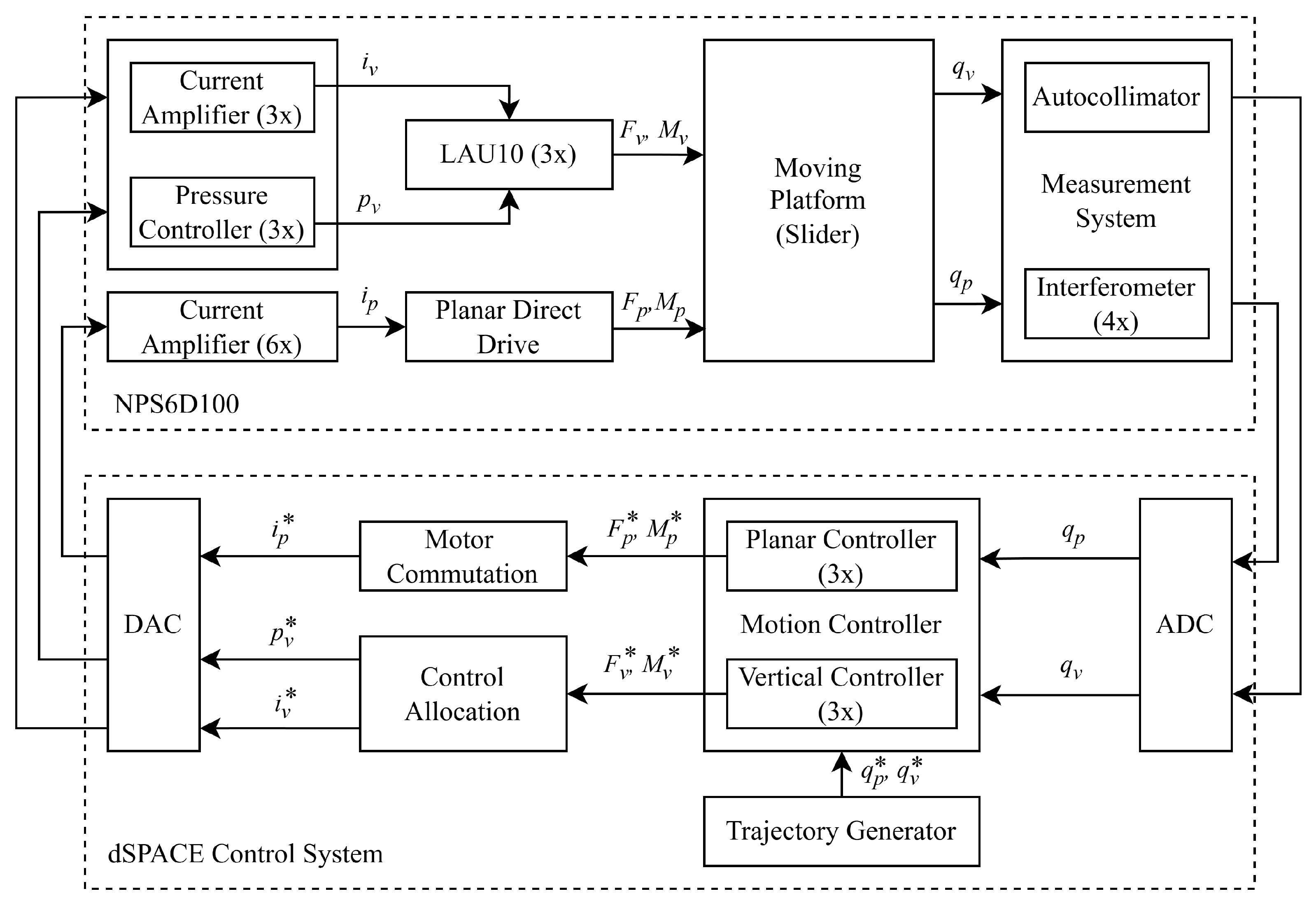
The control hardware used in the NPS6D100 is based on a dSPACE platform, which supports real-time control development and data acquisition. As shown in
Figure 3, the closed-loop system runs using a
sampling rate. During each cycle, 6-DOF feedback data (
,
) are acquired via the analog and digital inputs. These signals are subsequently processed to compute the setpoints (
,
,
) for the actuators. The target values for the planar actuators (
) and the vertical actuators (
,
) are transferred to hardware interfaces consisting of linear current amplifiers and high-precision pressure regulators. These components convert the control signals (
,
,
) into real quantities (
,
,
).
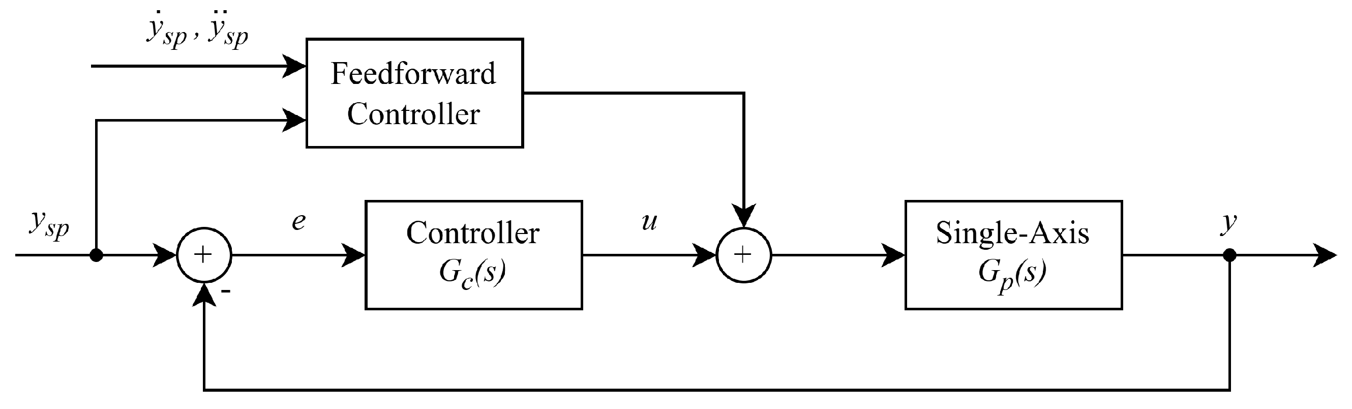
Individual feedback loops, one per axis, are implemented to achieve motion control across all six DOF.
Figure 4 depicts the closed-loop block diagram for an individual axis. Each control loop follows a conventional PID structure, which is widely used for nanopositioning systems because of its outstanding balance between implementation simplicity and performance effectiveness [
35,
36]. To further improve the precision and minimize oscillations caused by mechanical resonances in the high-frequency range, additional filters have been integrated into each control loop. Among the wide variety of available filters, low-pass filters and band-stop filters (also referred to as notch filters) were implemented.
The core of the motion controller is the PID-type structure that includes a filtered derivative term. In the time domain, the controller is described by
Equivalently, in the Laplace domain, the controller (
3) is expressed as
where
,
, and
are the proportional, integral, and derivative gains, respectively, while
determines how aggressively the derivative term is filtered. Each axis is tuned independently to ensure reliable performance, with sufficient robust stability margins in terms of gain margin, phase margin, and bandwidth. The control parameters are listed in
Table 4. Note that the PID parameters for all translational axes (
) share the same values, which is a mere coincidence. As introduced in
Section 2.3, the overactuated nature of the
z-axis is handled by means of a well-suited control allocation method, where the overactuated problem of the
z-axis is reduced into a SISO formulation similar to the
x and
y axes. The reader is referred to [
30,
31,
32] to complement the discussion on the control allocation criteria.
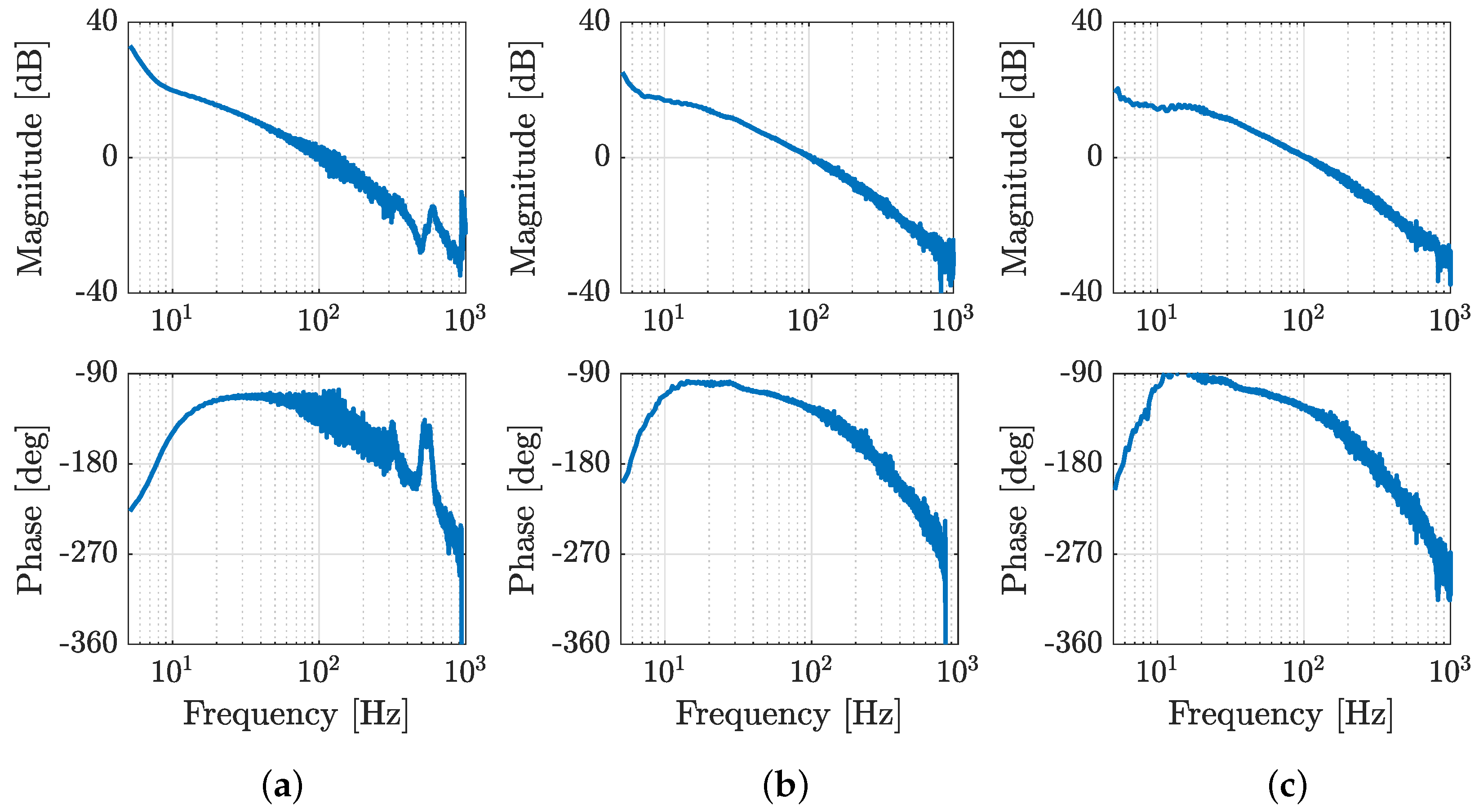
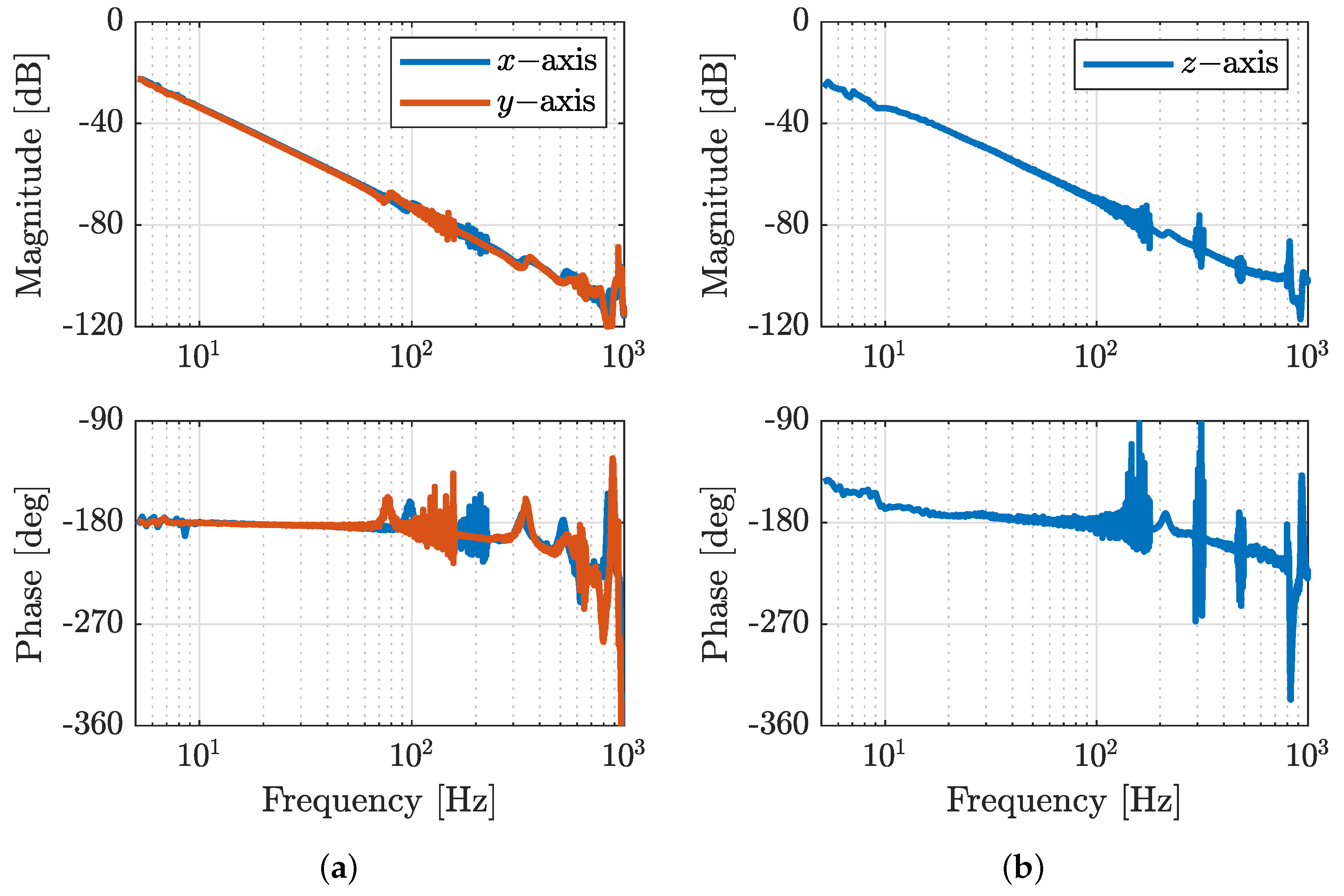
Figure 5 depicts the Bode plot showing the measured frequency response of the translational motion axes (
). The mechanical designs of the planar (
Section 2.2) and vertical (
Section 2.3) drive subsystems resemble the dynamics of a rigid body with mass and damping. Direct inspection reveals a decay of
dB per decade, reflecting the double integrator nature of the motion axes and the high stiffness in the actuation chain; see
Figure 5. Additional resonance modes in the high frequency band confirm the presence of structural flexibilities in the motion platform which must be attenuated through the controller. For completeness, the measured frequency response of the tilting angles (
) are shown in
Figure A1 (
Appendix A).
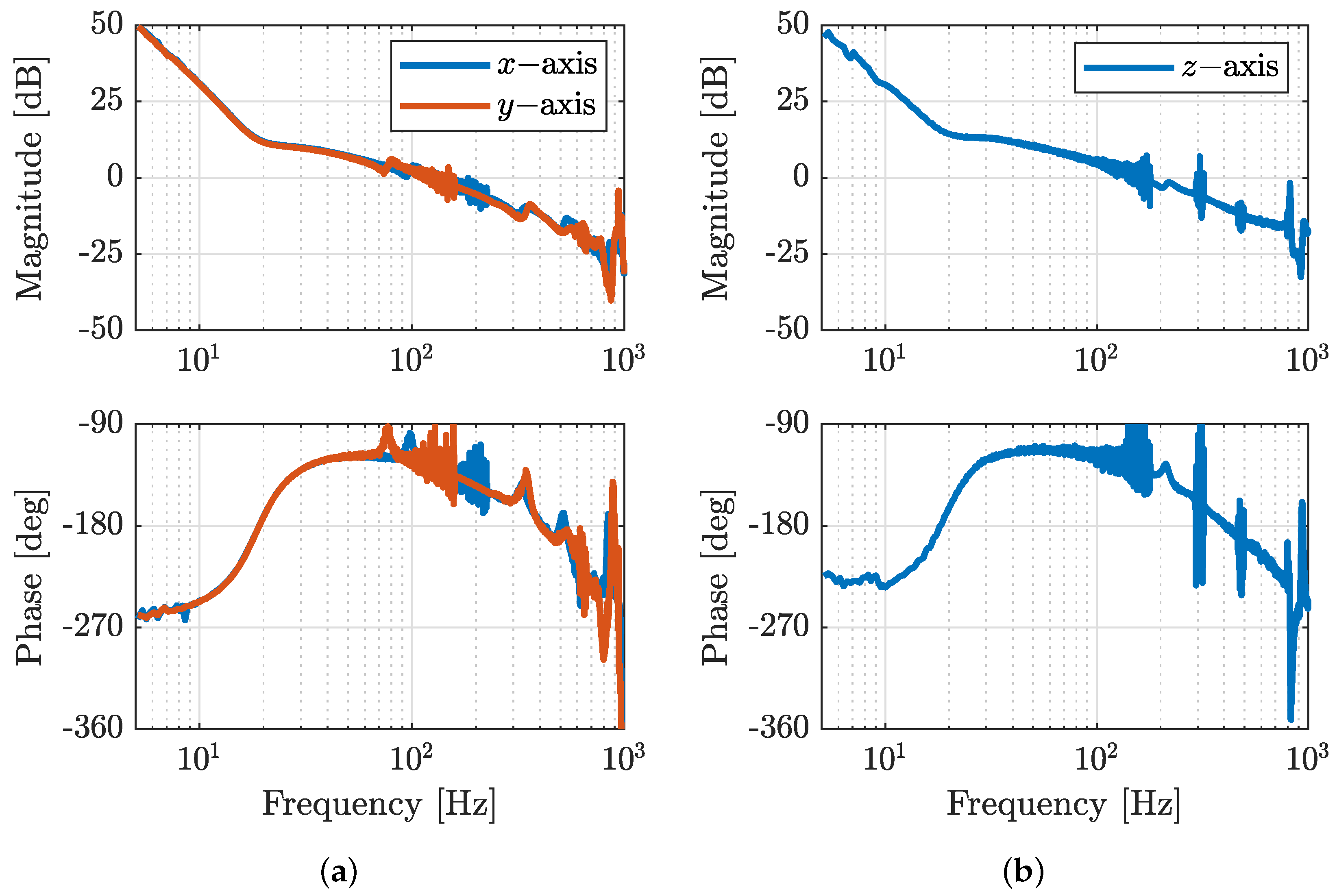
Figure 6 presents the open-loop response with clearly visible robust stability characterized by sufficient gain margins and phase margins. To reach these outstanding robust stability margins, the tuning procedure was performed offline based on the measured frequency response of the motion axes. Despite only the translational motion axes (
) being shown, the same tuning procedure was applied to the other rotational (
) DOFs. A summary of the control loop performance for all six motion axes is gathered in
Table 5. For completeness, the computed open-loop response of the tilting angles (
) are shown in
Figure A2 (
Appendix A).
Despite the overall robustness of the PID controller (
4), high-frequency resonances in the motion axes may still disturb the precision performance of the NPS6D100. Therefore, the control design integrates a series connection of notch filters and low-pass filters, specifically tuned to attenuate targeted resonances and preserve precise positioning. These filters reduce oscillations by attenuating undesired high-frequency components in the control signal. The low-pass filter suppresses high-frequency noise (usually above
), while the notch filter eliminates specific resonance frequencies that may produce vibration.
Even though the PID-based controller (
4) performs well, especially in steady-state and low-frequency motion tasks (as shown in
Section 4), it is not ideal for dealing with rapidly changing external disturbances or variations in system parameters. Such disturbing scenarios may require advanced control techniques. Several studies have explored advanced methods for handling periodic input disturbances and parametric uncertainty, as referenced in [
32,
33,
34,
37]. Furthermore, the interested reader may consult [
30], which describes the design and real-time validation of an advanced control concept in a large-scale motion system with nanometer precision, also referred to as NPS6D200.
4. Positioning Performance in 6D Closed Loop Control
This section presents the performance evaluation of the NPS6D100 nanopositioning system. Stationary and tracking exercises were performed to demonstrate that the motion system consistently achieves nanometer-level precision across the entire travel range.
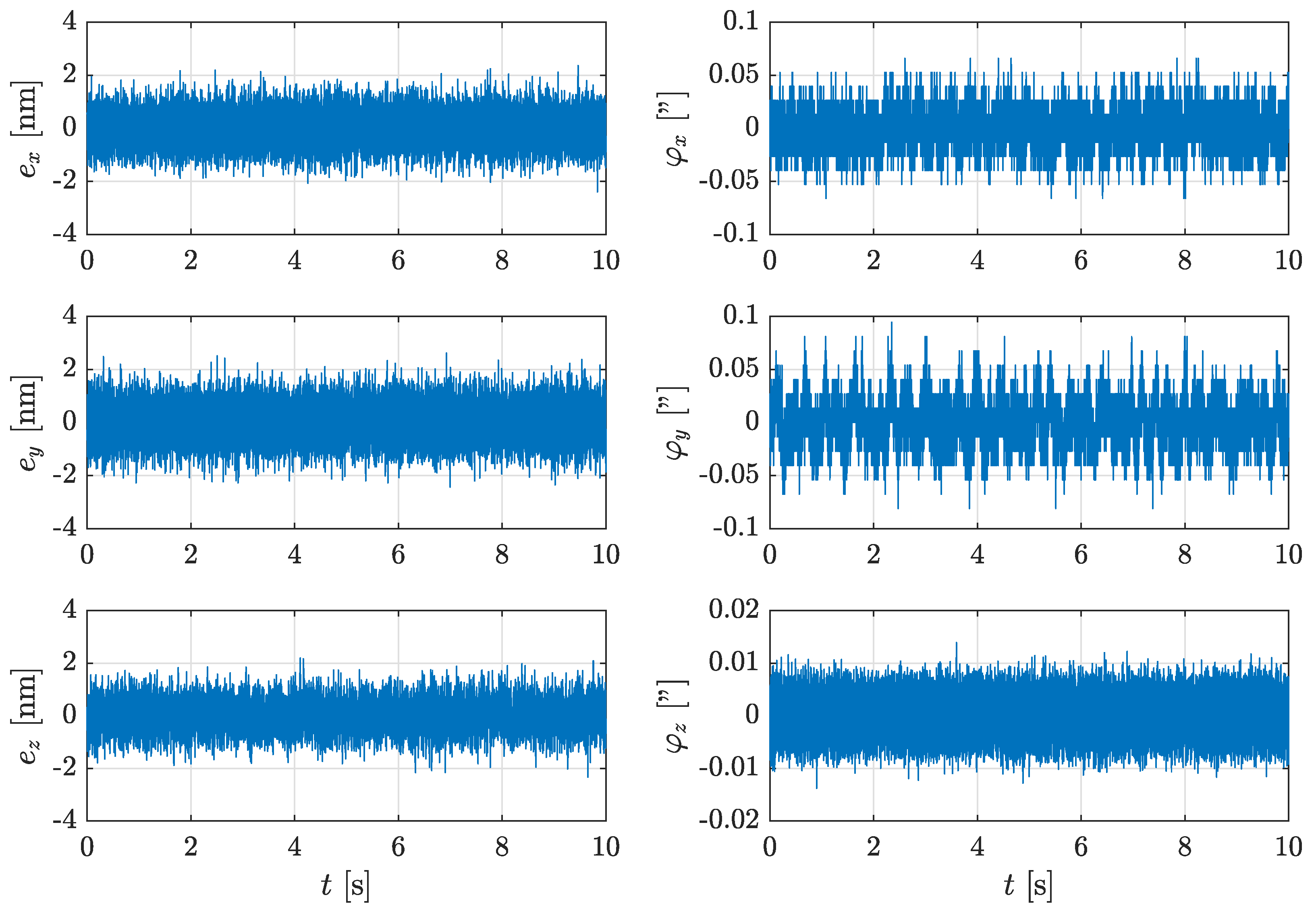
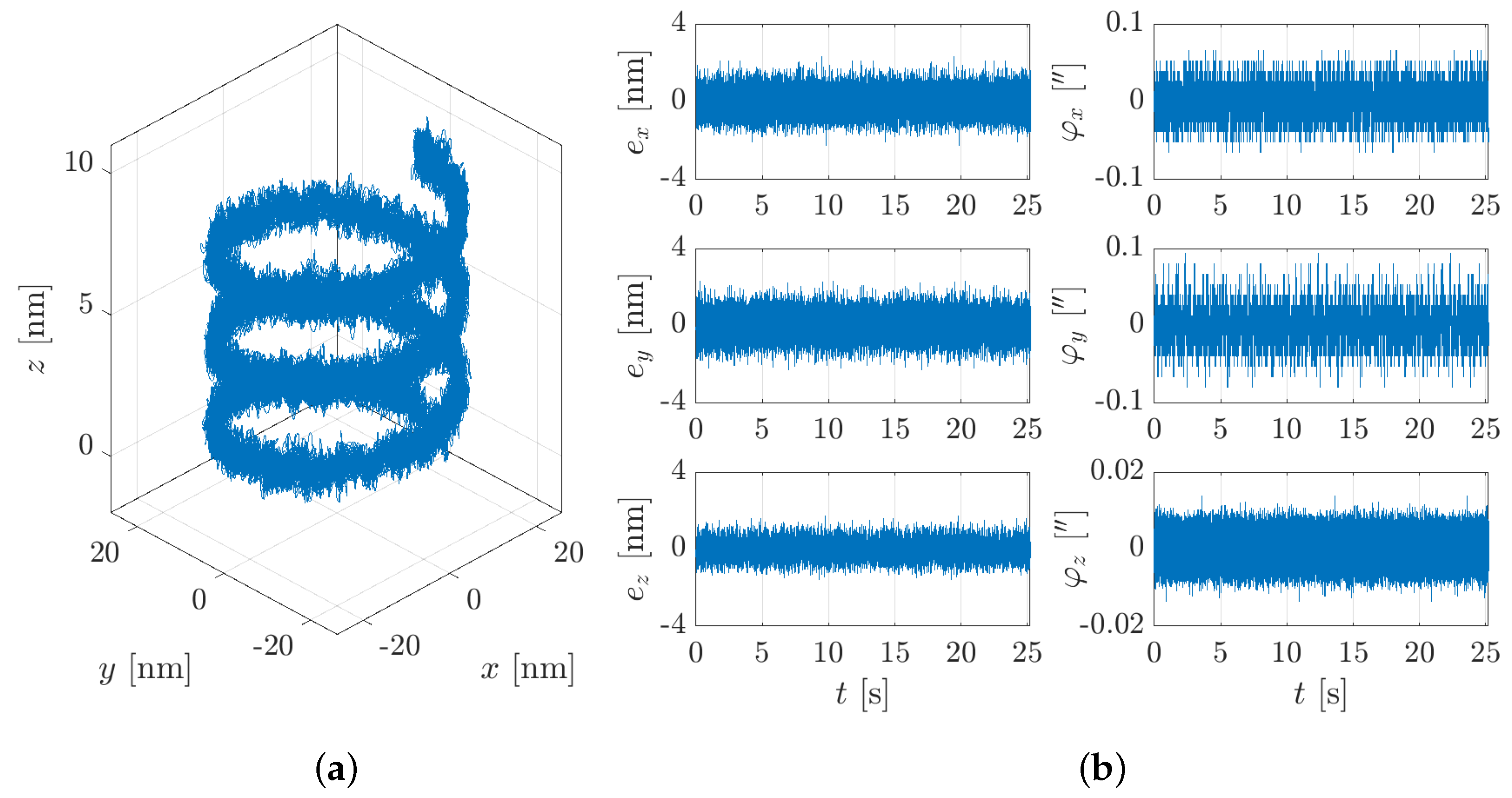
Initial experiments in closed loop operation evaluate the capability of the NPS6D100 to maintain a fixed position.
Figure 7 displays the time-domain responses of all six DOFs with the motion platform held at a fixed position in the center of the workspace. In this exercise, the position root mean square (RMS) errors are very low,
in
x,
in
y, and
in
z, and the angular RMS errors are also small, with
in
,
in
, and
in
. These results validate that the system meets the performance expectations during steady-state operation, achieving sub-10 nm precision under controlled laboratory conditions. It is worth noting that the RMS level observed in
Figure 7 reflects the influence of the control action but also contains the actual measurement signal noise. With a measurement resolution of
, the noise level of the measurement signal at the NPS6D100 is expected to be in the range of
standard deviation. In earlier investigations for a similar setup, the standard deviation of the fixed environment noise (with the controller switched off) was measured at
,
, and
; see [
6] for further discussion.
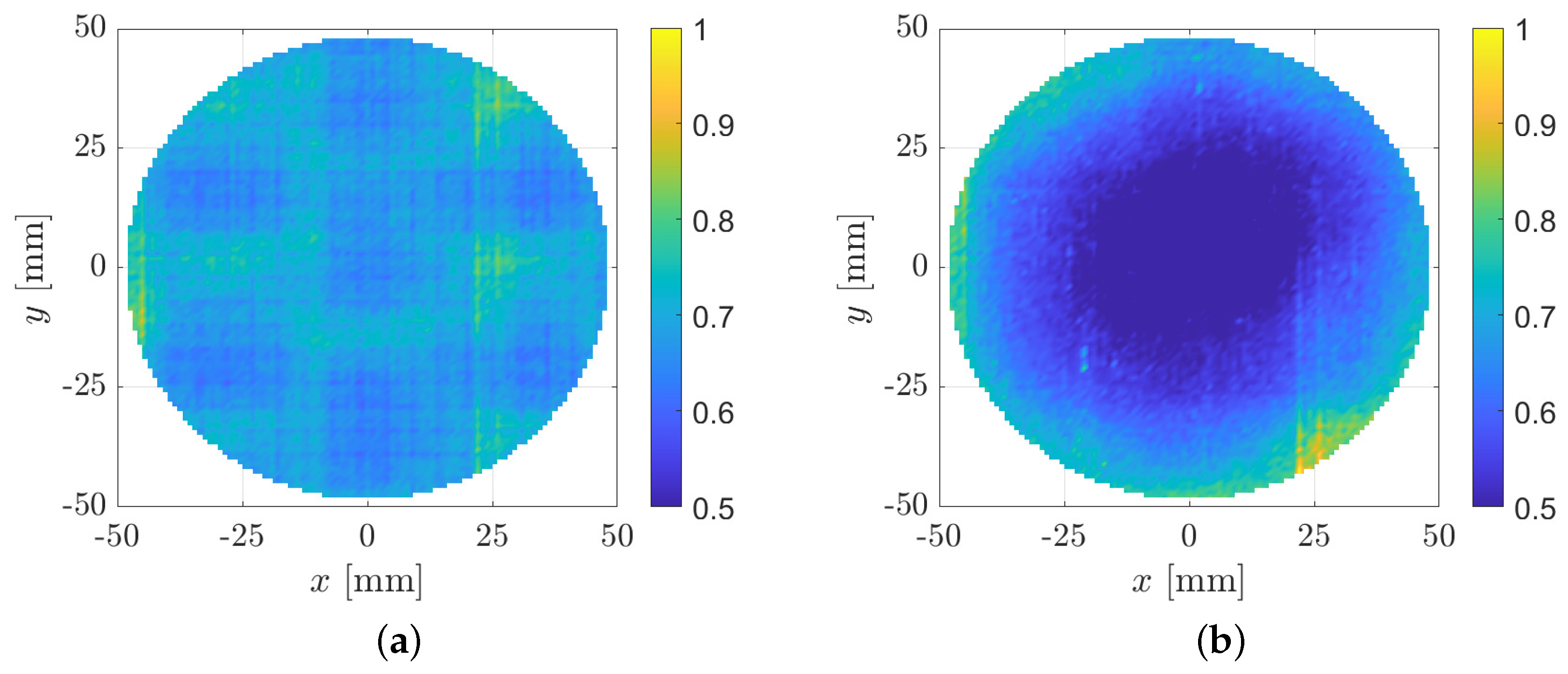
The subsequent analysis focuses on evaluating the positioning performance across the entire travel range. The measurement process was carried out by forming a grid with
spacing. At each point on the grid, the set of sensors measured the time series for one second and the RMS error was subsequently calculated and stored. As shown in
Figure 8, the planar (
) RMS error remained below
across the full
planar workspace. The vertical positioning achieves comparable RMS error levels, that is, below
.
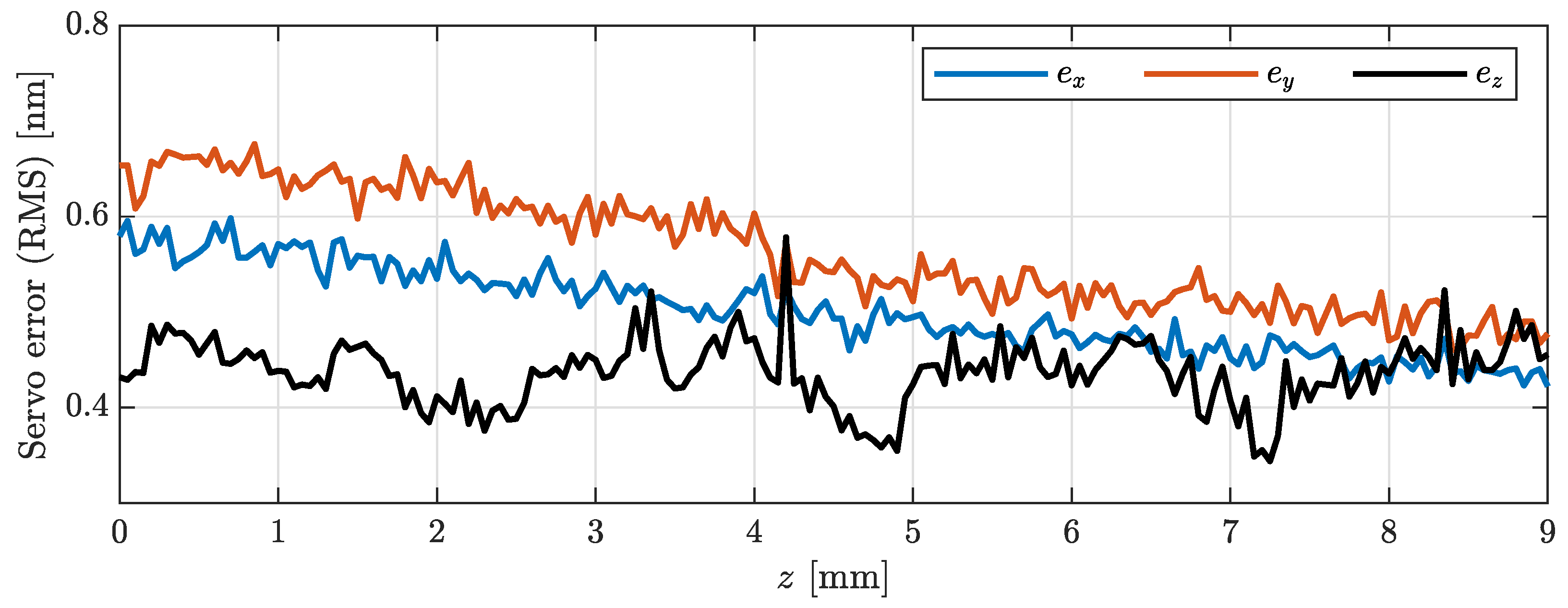
Figure 9 presents the servo errors along the
vertical range. The positioning errors in
x,
y, and
z remain in the nanometer-level and stable, even as the air gap between the planar coils and the permanent magnet arrays increases as height increases. These experiments show that the design without a coil lift system works effectively and, consequently, the direct force transfer behavior in the planar electromagnetic drivers remains stable over the whole vertical operating range.
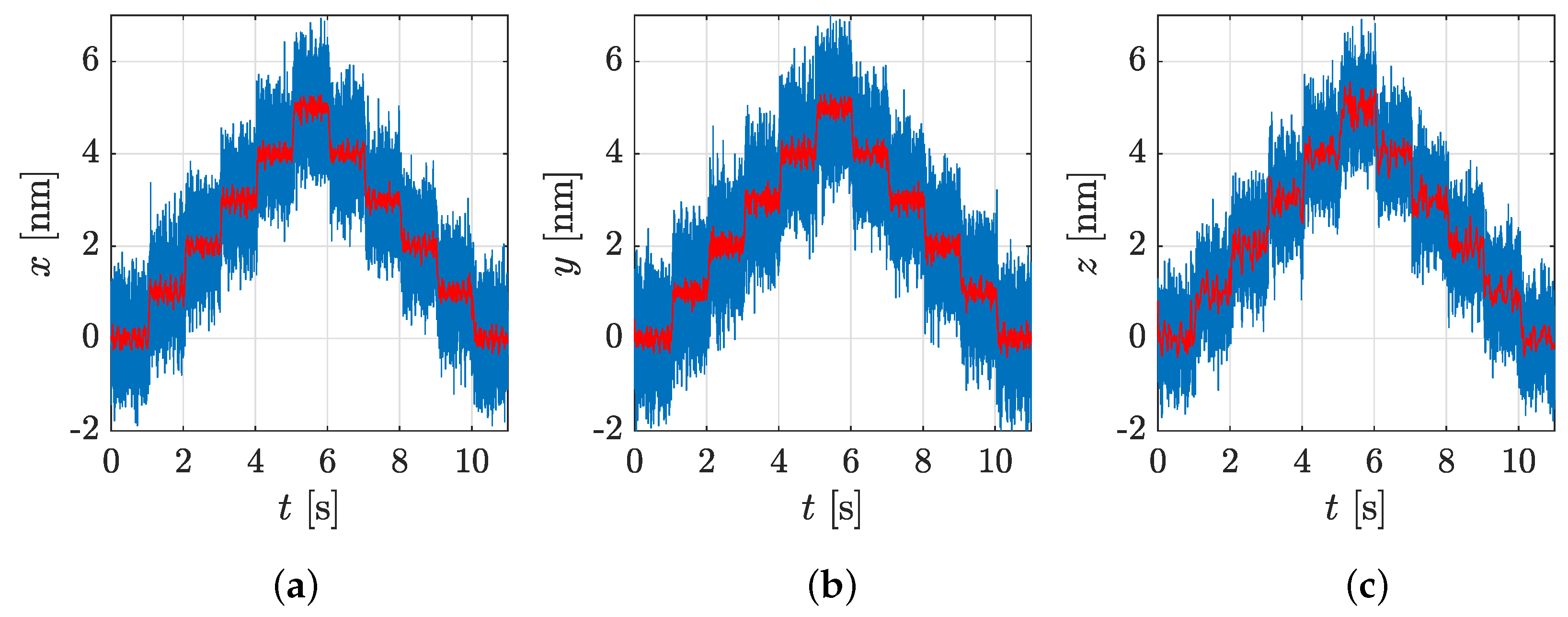
Then, step-wise motion experiments were carried out, which are fundamental in the field of precision engineering. Towards this end, the nanopositioning system NPS6D100 was commanded to perform nanometer-scale steps along the
x,
y, and
z axes, whereas the tilting angles (
,
,
) were regulated to zero.
Figure 10 illustrates the measured time series over a time span of
. The steps are clearly visible, featuring minimum noise amplification and no visible significant overshoots. The raw signal (in blue lines) and the filtered signal (in red lines) both confirm that the NPS6D100 can reliably execute nanometer-level steps in all three spatial position coordinates.
The capability to precisely follow complex 3D trajectories was assessed through helix motions of different dimensions ranging from the nanometer-level to the millimeter-level.
Figure 11 depicts a helix of dimensions Ø
traced with a velocity of
. The trajectory-tracking exercise was executed with sub-
RMS servo errors. Furthermore,
Table 6 summarizes these results for three helix sizes, including RMS errors and RMS currents. The nanopositioning system achieves RMS servo errors less than
across the macroscopic travel range, spanning from the nanometer to the millimeter scale. The low currents observed confirm the high efficiency of the drive units (planar and vertical) and the effectiveness of the low-dynamic weight force compensation mechanism integrated into the lifting modules.
5. Conclusions and Outlook
The NPS6D100 represents a solution where the coil lift system is not required and thus completes the range of positioning solutions that combine an integrated planar direct drive with direct vertical actuation. In direct comparison to the NPS6D200 [
28,
29], the working range and the coil lift system are the main differences, resulting in disturbance reduction and improved positioning performance.
The NPS6D100 is a high-precision nanopositioning system that enables 6-DOF motion within a Ø workspace. The motion system was designed for sub- applications; it combines a 3D planar Lorentz-based direct drive, aerostatic guidings, and vertical actuation to achieve precise and reproducible motion across all axes.
A key feature of the NPS6D100 is the integration of three custom-developed LAUs, each combining a voice coil (electromagnetic) direct drive, a low-dynamic pneumatic weight force compensation, and an aerostatic bushing into a compact lifting module. This design ensures precise vertical positioning with minimum heat dissipation, making it suitable for long-term precision tasks without disturbing the measurement space. Each LAU also includes an internal vertical encoder for standalone initialization and control.
The measurement system uses a Cartesian mirror arrangement with three LIFs and a 2D autocollimator to provide high-resolution feedback in all six DOFs. This setup supports precise, closed-loop control and eliminates first-order Abbe errors. The system demonstrates sub-nanometer RMS servo errors under stationary setpoint conditions and maintains nanometer-level tracking performance during dynamic synchronous multiaxial motion.
The mechanical structure is compact and dynamically stable, and its performance under different motion conditions shows minimum variation in positioning precision. The NPS6D100 operates efficiently within the complete travel range, with vertical displacements of up to , without introducing significant cross-coupling between axis or affecting the direct force transmission between the planar coils and the permanent magnet array.
The combination of stiffness, compactness, and high-precision measurement instruments makes the NPS6D100 well-suited for demanding applications such as sub- fabrication, long-range optical probing, and sample handling in nanoscale inspection or lithography.
Future developments will focus on investigating in situ calibration routines and integrating tool-specific probes to expand the functionality of the NPS6D100 within the nanotechnology field.


