Abstract
Rehabilitation robotic systems have been developed to perform therapy with minimal supervision from a specialist. Hence, they require algorithms to assess and support patients’ motions. Artificial intelligence brings an opportunity to implement new exercises based on previously modelled ones. This study focuses on analysing the similarities in upper extremity movements during activities of daily living (ADLs). This research aimed to model ADLs by registering and segmenting real-life movements and dividing them into sub-tasks based on joint motions. The investigation used IMU sensors placed on the body to capture upper extremity motion. Angular measurements were converted into joint variables using Matlab computations. Then, these were divided into segments assigned to the sub-functionalities of the tasks. Further analysis involved calculating mathematical measures to evaluate the similarity between the different movements. This approach allows the system to distinguish between similar motions, which is critical for assessing rehabilitation scenarios and anatomical correctness. Twenty-two ADLs were recorded, and their segments were analysed to build a database of typical motion patterns. The results include a discussion on the ranges of motion for different ADLs and gender-related differences. Moreover, the similarities and general trends for different motions are presented. The system’s control algorithm will use these results to improve the effectiveness of robotic-assisted physiotherapy.
1. Introduction
Available data estimate that 15% of Europeans are affected by various types of disabilities, which means an average physiotherapist should work with 182 patients simultaneously to meet European needs for rehabilitation specialists [1]. Due to the shortage of medical staff, only the development of additional technologies can provide sufficient access to physiotherapy for society [2].
Rehabilitation robots are one such tool. They allow physical performance to be recovered in a controlled manner with limited engagement of physiotherapists [3,4,5,6]. This field is developing quickly, and many supporting devices are available commercially [7]. However, new solutions are still being introduced into the biorobotics industry. The rehabilitation devices focus on increasing the availability, frequency, and length of kinesiotherapy sessions, improving the quality of exercises, and reducing the effort of physiotherapists [8]. Nevertheless, this requires new tools for providing patient safety with minimal supervision from a specialist [9,10].
Rehabilitation robots can be divided into end-effector types and exoskeletons. The former enable easier use and the easier implementation of safety features but do not control the full rehabilitated segment configuration. Only the point of contact with the robot can be defined [7,8,9,10,11]. On the contrary, exoskeletons enable the monitoring of every single joint and support but introduce risks from potential misalignments or bad dimensional adjustment [12,13]. Nevertheless, their complete control over the kinematic chain is preferable in the use of multiple devices by a single operator or even telerehabilitation [10].
Treatment with an exoskeleton of an extremity is based on the exercise trajectory repeated by a patient with the device. Depending on the personal needs, the therapy can be realised in either a passive or active mode [14]. The former is dedicated mainly to individuals with higher levels of disability. The exoskeleton fully supports the motion and drags the extremity to activate joints and muscles. The latter comprises the system support or resistance and the movements of a patient [15]. For such an approach, the motion intention of a user needs to be sensed [16]. Nevertheless, these motions must be corrected automatically, as the physiotherapist would do. The intended exercises can be registered by pulling the exoskeleton manually, via the digital model or from the preregistered databases. Then, these are looped and realised automatically with control algorithms reacting to the user intentions and the differences between planned and performed actions. Thanks to this, the robot can overtake the physical tasks of a specialist [8].
Moreover, the simultaneous rehabilitation of multiple patients is possible with several machines in one medical facility. Such a process only requires one physiotherapist to supervise rehabilitation sessions. After the initial setup of the robots, a specialist can be almost entirely replaced by technicians performing the physical tasks of attaching users to the devices. The presented solutions can solve the healthcare challenges mentioned above.
However, rehabilitation robots require automatic control algorithms to assess patients’ performance and adjust exercises to individual needs [17]. Currently, this process is often realised by comparing the desired and reached trajectories or the exerted and expected forces [2,18,19]. Nevertheless, a physiotherapist is performing such supervision in a more complex manner. They include the observation of additional aspects such as anatomical compensations and functional errors, which can lead to cognitive recalling of unanatomical motion patterns or loading the musculoskeletal system ununiformly, which is potentially dangerous for patients [20]. The solution of providing advanced supervision over the kinesiotherapy process should consider patient’s motion intentions, their accuracy of following the reference trajectory, and an assessment of the anatomical compensations and functional errors [21]. As the last two are strictly related to the type of motion realised (e.g., the motion of drinking is correlated with the possible functional error of excessive tilting of the mug and the anatomical compensation of excessive shoulder abduction, which cannot apply to other similar types of motion), a deep knowledge of treatment motions is needed for rehabilitation to be effective.
Rehabilitation based on the International Classification of Functioning, Disability and Health (ICF) is an approach that focuses on a holistic understanding of a patient’s health. Instead of focusing only on a medical diagnosis, the ICF considers various aspects of a patient’s life, such as function, activity, social participation, and environmental factors. With this approach, rehabilitation is tailored to the patient’s needs, allowing for better support in returning to full function and social integration [22]. The task-oriented treatment is based on recalling Activities of Daily Living (ADLs) and Instrumental Activities of Daily Living (IADLs) to enable individuals to become more independent and perform the most important activities for themselves.
ADLs and IADLs are two key terms used in assessing people’s functioning, especially in the context of healthcare and rehabilitation. ADLs refer to basic activities of daily living that are necessary for independent functioning. These include activities such as eating, dressing, bathing, toileting, moving around (such as getting out of bed), and controlling physiological needs. IADLs are more complex activities significant for independent living in the community but not directly related to basic physical needs. Examples of IADLs include preparing meals, shopping, managing finances, using public transportation, cleaning, and managing medications [23].
As the target of treatment is to recall motion patterns for ADLs and IADLs it is required to model the motion trajectories of these. As some of the movements are similar, it is required to define potential confusion and prepare an algorithm to distinguish them. Moreover, potential anatomical compensations and functional errors need to be modelled and assigned to certain motions. Thanks to this, a control algorithm of the exoskeleton will be capable of avoiding them.
This study aims to model common ADLs and IADLs (further referred to as ADLs only) based on the registered motions and analyse their similarities. The method targets the further use of the registered motions for robot-aided physiotherapy. For such an application, it is critical to divide the ADLs into task-related segments and model potential functional mistakes and anatomical compensations, which are typical for neurological or orthopaedic patients. Thanks to this, the physiotherapy exoskeleton using the models will be able to assess not only the trajectory following (for the state-of-the-art technologies) but also the functionality, anatomical correctness of the motions, and intentions of motion regarding the trajectories to be followed. Therefore, the investigation will include registering real-life motions, segmenting them, processing them to obtain variables corresponding to the encoder measurements for the rehabilitation exoskeletons, and comparing one to another. As a result, a set of similarities between specific segments will be developed. Thanks to using the study’s outcomes, it will be possible to increase the effectiveness of detecting patients’ intentions based on learning [24] or proportional algorithms [16], which can confuse relatively similar trajectories. Moreover, it will be possible to augment the training database by creating new motions as combinations of the registered ones. The method will be applicable mainly to exoskeleton-based systems, as it relies on the parallel kinematic chain measuring the motion of the extremity [25].
2. Materials and Methods
This section describes the experimental setup, software, and methods used at every stage of the investigation. This refers to the motion registering, post processing of data with the original MBD computation software, segmenting motions, comparative analysis, and data visualisation.
2.1. Experimental Setup
The investigation results presented in this paper will be used in an intelligent control system of an upper extremity exoskeleton developed within the SmartEx-Home project [26]. The exoskeleton kinematic chain contains five degrees of freedom (three active and two passive), presented in Figure 1. These enable the full mobilisation of the elbow and shoulder joints with free rotation along the long axes of the arm and forearm.
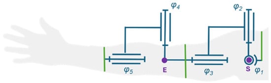
Figure 1.
Kinematic chain of the exoskeleton in a default position (φi refers to the i-th DOF joint variable of the kinematic chain, purple dots represent modelled joint centre points (E for elbow and S for shoulder), green lines represent attachment of the exoskeleton to the user).
The control system of the exoskeleton is intended to enable the complex assessment of any exercise based only on its trajectory. Initially, the registered motion will be automatically divided into expected subsegments. Then, a neural model will assess each of them regarding similarities to the modelled ADLs. Based on these, the potential anatomical compensations and functional errors will be defined within the potential configuration hyperplanes. With these, the assessment module will be capable of analysing the correctness of motion and computing the required support of the drives, which will be executed directly with the low-level controllers. The block diagram of the control algorithm is presented in Figure 2.
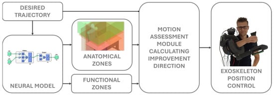
Figure 2.
Block diagram of the exoskeleton’s control system. The individual depicted in the figure have provided explicit consent for his image to be used in this paper.
This study presents the process of building a database of ADLs and searching for similarities among the registered motions, which can be used to improve the accuracy of the neural classifier.
2.2. Modelled Motions
Twenty-two ADLs essential for independent functioning and independent living in society were selected. These movements include various aspects of daily life, such as drinking, eating, preparing meals, maintaining personal hygiene, cleaning, moving around, and using transportation [27]. Each of these is important to ensure that patients can lead autonomous lives without needing constant support from caregivers. Every type of motion was divided into shorter segments based on the realised subtasks and monotony of joint rotations.
Then, possible anatomical compensations and functional errors were defined for the segments. Compensations are considered replacement movement mechanisms that patients develop in response to physical limitations or pain. They can include changes in posture, how activities are performed, or engaging different muscle groups than under typical conditions. Functional errors, on the other hand, are patterns that fail to achieve the goal of an activity. These include reaching a different point than the acceptable target (e.g., for reaching the object or eating), losing angular orientation (e.g., for drinking), or realising the whole trajectory with excessive inaccuracy (e.g., for turning wheelchair wheels).
Every motion and its segments were labelled with their unique enumerations (XXX—three-number standard for motions; XXX-YY—three-number standard for the assigned motion with a two-number standard for a selected segment). Anatomical compensations and functional errors were assigned to these numbers. Therefore, every segment is dependent on a motion, and every compensation or functional error is dependent on a segment. Hence, theoretically, these malfunctions cannot be considered for motions other than those modelled.
2.3. Motion Registering
In this research, four IMUs placed on the subject’s body, as shown in Figure 3, were used to measure the motion of the upper extremity. These were selected as an alternative to traditional vision-based motion capture systems, which are often prohibitively expensive and require complex setups [28,29] with acceptable accuracy and reliability [30]. A Movella DOT system, recording with 120 Hz frequency, was used for the measurements. Each sensor is equipped with a 3-axis gyroscope, a 3-axis accelerometer, and a 3-axis magnetometer [31]. The software provided by Movella was used to register orientations of single sensors as ZYX Euler angle triples.
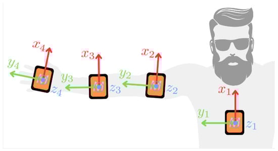
Figure 3.
Placement of four Movella DOT sensors (size increased for visibility) on the subject’s body and the default position used during the initialisation phase (the IMUs’ local coordinate frames presented for clarity).
Although most of the modelled ADLs involve the body remaining relatively still while only the upper extremity was in motion, one additional IMU was placed on the trunk to consider natural changes in its position during the recorded activities. Another two IMUs are placed on the medial areas of the arm and forearm. The fourth unit was attached to a palm, which was highly important for computing forearm supination/pronation. This placement also provided information on the two degrees of freedom in wrist motion, which were used to analyse the motions but do not apply to the exoskeleton with the kinematic structure presented in Figure 1.
The ADLs were recorded in a room where previously a magnetometer calibration was conducted and in a space where the disturbances of the gravitation force norm are less than 10%. Each recording session was completed within 5 min, which is a period in which the drift of IMUs is negligible. The following procedure has been established to ensure consistent data measurements:
- Conduct heading reset of IMUs;
- Hold the extremity still in a default position;
- Repeat the investigated ADL ten times;
- Finish the recording and transfer it to a hard drive.
A heading reset was required before each new recording. Besides aligning the axis of the IMUs in the same direction, this step restrained the issues with axis recognition. The recorded subject held the extremity still in a default position (anatomically neutral, as shown in Figure 3), which we refer to as the initialisation phase. Although there are methods for conducting such research calibration- and alignment-free [32], the initialisation posture approach was simple and effective and did not require further optimisation-based modifications to the recorded dataset. Hence, the accuracy of the results was superior. An initialisation time of 5 s gave the best results. Still, due to the different conditions of the subjects, a 0.5 s initialisation length was selected as the minimum for performing the following computations.
Each ADL’s recording session was completed within 5 min, a period in which the measurement units’ drift is neglectable [33]. In the last step, the recorded data were transferred from the Movella DOTs to the mobile application to the standardised datasheet. All experimental trials were also recorded with a camera for further analysis.
2.4. Motion Processing
Processing of raw recordings from the database was conducted within the MATLAB R2024a environment. The input data consisted of the time history of Euler XYZ angles:
representing IMU orientations, where i denotes the time step, j is the IMU number, and α, β, and γ correspond to rotations around the local X, Y, and Z axes, respectively (see orientation of the sensors in Figure 3). The procedure for computing rotations of the modelled joints from Figure 1 was divided into the following steps:
- Load data and remove measurement value range limits;
- Compute the initial orientations of the IMUs;
- Assume default orientations of the body segments’ frames;
- Compute the motion of the body segments’ frames;
- Compute the rotation history in the joints.
After loading the data, rotation recordings , originally clipped within the range , are transformed into an unbounded domain to prevent discontinuous changes in their values during further processing. This transformation into an unbounded sequence , is performed based on a sensitivity parameter . Specifically, the transformation applies a shift of ±2π to the subsequent values only if . This parameter is necessary as the orientation may change due to IMU motion between steps where the measurement was clipped, and the difference between consecutive steps is not precisely equal to 2π. The value of allows the algorithm to detect clippings correctly and quick motions remain unmodified.
The next step involves computing initial orientations of the IMUs. The angle values captured during the initialization phase, as described in Section 2.3
are averaged to establish a reference initial position. This position is then used to calculate relative rotations and apply them to the assumed default orientations. In addition to determining the initial orientation in terms of Euler angles , a rotation matrix is also computed (column-wise rotation matrix representing IMU frame orientation in the global frame; a convention used in subsequent derivations).
The assumed default orientations of the frames of reference correlated with the body segments are illustrated in Figure 4. For the trunk, the default orientation coincides with the global frame. The X-axis is aligned with the respective segment’s long axis for the arm and forearm frames. In contrast, the Y-axis is oriented in the opposite direction to the gravitational force in the default configuration. The frame corresponding to the palm shares the same default orientation as the forearm frame. This specific arrangement of the frames simplifies the subsequent task of determining the joint rotations. It is important to note that, at this stage, the carrying angle of the elbow is assumed to be 0.
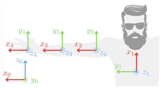
Figure 4.
Coordinate frames O (x_i y_i z_i) corresponding to the trunk, arm, forearm, and palm (i = 1, 2, 3, 4, respectively) in their default orientations. The global coordinate frame is designated as O (x_0 y_0 z_0).
The fourth step involves computing the motion of the body segments’ frames. At each time step, the rotation of the IMU relative to its initial orientation is determined and then applied to the default orientation of the corresponding body segment. This process is repeated for all recorded steps of motion using Formula (1):
where is the body segment orientation matrix at i-th step, is the assumed default orientation matrix of the j-th body, and is the permutation matrix that accounts for different axis directions between the default orientations and the global frame. For j = 1 (the trunk), is the identity matrix, and for the other segments presented in Equation (2).
is the orientation of the j-th IMU at the i-th step.
Similarly to the computation of segment motion, the joint rotations (φ1–φ5 as seen in Figure 1) are calculated for all recorded steps. The joint variables of the first three degrees of freedom (DOFs, φ1–φ3), which correspond to the shoulder joint, are determined using Equation (3):
where is the rotation matrix at the i-th step that represents the orientation of the arm frame relative to the trunk frame, excluding the rotation necessary to transform between the default orientations of these segments. The ZYX Euler angles corresponding to are then computed to obtain the desired DOF rotations for the shoulder joint (φ1–φ3).
Next, the joint variables related to the elbow (φ4 and φ5) DOFs are computed. This process begins with the Formula (4):
where is the rotation matrix analogous to , and is a rotation matrix around the local X-axis by . From this point, the corresponding set of ZYX Euler angles is obtained. The rotation matrix is used to align the arm’s Z-axis with the DOF 4 rotation axis. In the case of a fully extended elbow, represents the carrying angle. The value of is set by the operator during the labelling process (see Section 2.6 for each recording, such that the standard deviation of is minimised, φ4 is then taken as . However, alone is insufficient to represent DOF 5 (φ5), as additional information about supination/pronation, which this DOF corresponds to, is also contained within the orientation of the palm and the rotations related to the wrist. This is described with the Formula (5):
where the angles are transformed to XZY Euler angles capturing the remaining part of the DOF 5 rotation with . Consequently, the final DOF 5 rotation is defined as . Once computed, the additional wrist-related DOFs, φ6 and φ7, are assigned the values , respectively.
2.5. Data Structure
A database of the 22 most popular ADLs was created with real-life measurements of male and female subjects. Then, the motions were segmented to represent the subtasks of every motion (e.g., the motion of taking an object from the shelf was divided into reaching the object and taking it down). One session of ten repetitions of each movement was recorded per subject. This resulted in 115 unique segments (used as the input for the neural model classification task), represented by the 2088 time series. A sample segmentation of the chosen movement is shown in Table 1, and the full table of segmented motions can be found in Supplementary Materials Attachment S1. Activities 18, 19, and 22, considered typically gender-dependent movements, were recorded only by male subjects. This is because persons unfamiliar with the motions can perform them unfunctionally. Hence, it can result in the wrong modelling of the joint movements for the tasks. These include putting lipstick on (female only), shaving the beard (male only), and combing men’s hair (male only).

Table 1.
Segmentation of the exemplary ADL.
Every recorded segment is considered a time series with the combination of five independent joint variables. As the ADLs are considered for application in the rehabilitation exoskeleton represented with a kinematic chain in Figure 1, the DOFs of the wrist joint were not stored in the database.
2.6. Motion Segmentation
The registered ADL motions were divided into segments depending on the direction of movement in the joints. This division allows for a better understanding and analysis of the actions performed. These differ from one another in terms of involved ranges of motion and muscle engagement.
During the segmentation of movements, a programme developed for this project only was used. It enabled the simultaneous comparison of recorded videos from the trials synchronised with multibody model animation and the time graph representation for individual joints (see Figure 5). The start and end of each segment were determined using animation, with each subsequent segment beginning with a change in the direction of movement in a specific joint. This is confirmed by the charts, which show changes in the range of motion values in the corresponding joints. The charts were divided into segments, each of which was given a name and marked with a different colour, as presented in Figure 6. In total, the database of 2095 recorded segments was gathered.
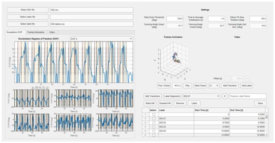
Figure 5.
Graphical user interface of the developed software for processing the registered trajectories (motion trajectories divided into recomputed seven DOFs on the left side with an option to add motion subsegments, stick model and the video optional preview on the top right side, and the segments labelling window on the bottom right side).
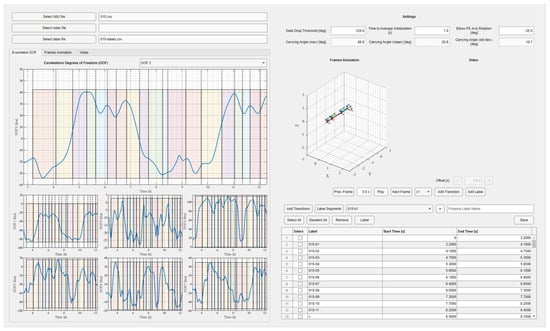
Figure 6.
Graphical user interface of the developed software with the computed joint trajectories for the considered kinematic chain with the segmentation applied (the same colours of the intervals correspond to the same motion segments in the following repetitions).
2.7. Mathematical Methods for Similarity Analysis
First one is the sum of the Euclidean distances between time points of the two trajectories. This, after simplification of the formula caused by one-dimensional analysis, is given by the following formula:
where n is the number of signal samples, and x and y are two given time series. The lower the value of this metric, the higher the similarity of the signals is. The presented measure is not normalised, but the results correctly represent the similarity of the given signals. It is a measure that sums up the differences in the angular positions of given consecutive samples and, therefore, checks how strongly the signals deviate from each other. Values were computed separately for each of the five DOFs of the considered kinematic chain.
The second measure is the Pearson correlation coefficient, given by the formula:
where n is the number of samples of the signal, x and y are two timeseries of movements, and the dash above the sign indicates the average value of the signal.
Pearson’s correlation coefficient is a normalised measure. To analyse the similarity of the movements empirically, a value of 0.7 was selected as a strong correlation threshold. This measure examines similarity in terms of linear correlation for two signals. Therefore, a strong negative correlation is not essential in the context of the study.
3. Results and Discussion
3.1. Motion Analysis
The trajectories of motions achieved during recorded ADLs were analysed to compare them between genders and according to the anatomical assumptions. The ranges of the recorded motions are presented in Table 2.
Table 2.
Ranges of motion observed during particular movements.
The ranges for DOF1 (abduction and adduction in the shoulder joint) vary from 60.41° to 170°. The full utilisation of this range is observed during movements such as throwing or reaching for an object on a high shelf, where raising the upper limb to a significant height engages DOF1 as the first element in the kinematic chain. In contrast, the smallest ranges of motion in this plane occur during activities close to the face, such as applying lipstick or brushing teeth.
The ranges for DOF2 (flexion and extension in the shoulder joint combined with horizontal abduction and adduction) range from 30.83° to 159.18°. The highest values were recorded during activities like vacuuming or driving a car, while the lowest was observed during tasks such as washing the upper back. The engaged range of motion is mainly correlated to the position of the target points of the hand’s characteristic point. The range increases with multiple points placed laterally, while it narrows with the points placed medially.
DOF3 (rotation in the shoulder joint) ranges from 27.11° to 160°. The rotations are particularly intensive during movements such as reaching for a shelf, throwing, or combing hair, while the smallest values were recorded during activities like drinking or eating with utensils.
DOF4 (flexion and extension in the elbow joint) ranges from 69.23° to 144.74°. The largest ranges appear during tasks like washing the upper back or throwing, and the smallest during pushing movements. It is possible that the extensive range in the elbow joint during back washing compensates for shoulder flexion. However, this requires further study.
DOF5 (pronation and supination in the elbow joint) ranges from 28.7° to 162°, with the highest values observed during driving and the lowest during wheelchair use.
The most significant differences between women and men were noted in activities such as vacuuming, pushing, and stirring. Universally, the largest ranges of motion are observed during throwing. Moreover, an inverse correlation between the ranges of motion in shoulder and elbow joints can be observed.
3.2. Motion Similarity
The Euclidean distances between the time points of the two trajectories and the Pearson correlation were evaluated for all of the recorded ADLs. Each of them was analysed separately for every DOF. Moreover, they were divided into subsegments and compared to one another for multiple trials. The motion segments were considered correlated for the p-value below 0.05. For ease of visual analysis, correlation matrices were generated for the limited number of motion segments compared. Nevertheless, a big matrix comparing all the segments was constructed as well.
The graphs presented in Figure 7 and Figure 8 were created for the movement 001 (pulling an object, a cup, out from a cabinet). The movement was divided manually into three segments: lifting an extremity (001-01), reaching for an object (001-02), and retracting a hand with an object (001-03). The Pearson correlation matrix and Euclidean metric sum values for all degrees of freedom were generated for ten recordings of this movement. Both measures require the same number of samples in the signal, so the data were interpolated to the maximum value registered in the mentioned segments. The experiment validated the selected measures for evaluation on the entire database. This included the analysis of motions performed by different participants and comparing non-related segments.
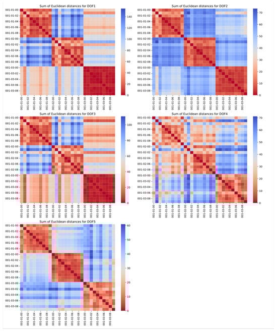
Figure 7.
Sum of Euclidean distances for motion 001 (repetition of the same tasks compared in rows and columns; enumeration is built in the form of task–segment–repetition; each graph represents other DOF of the model).
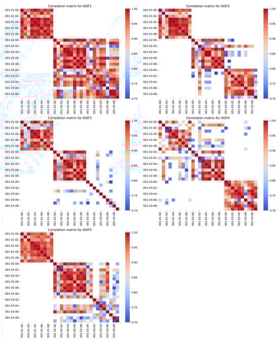
Figure 8.
Correlation matrices for motion 001 (repetition of the same tasks compared in rows and columns; enumeration is built in the form of task–segment–repetition; each graph represents other DOF of the model).
The correlation matrices prove the correctness of the selection and interpretation of both measures. The corresponding segments in the different recordings show high similarity, marked by red in the visuals. This is an expected result, which can also be helpful in searching for inaccurate recordings or labelling errors. Calculations for the rest of the ADLs, with respect to each other, can be found as a Supplementary Materials Attachment S2 to the paper.
As can be observed, the sum of Euclidean distances is a more robust metric. However, the Pearson correlation also shows high values between consecutive recordings. In the presented example, only DOF3 in the 001-03 segment is not clearly correlated, but this helped the researchers to capture human errors in the data labelling or, as in this case, the stationary course of this DOF in the given segment. The only risk of using this metric to detect monotonicity changes between the segments is the inability to capture strongly nonlinear relationships.
Each of the 22 recordings shows similar trends for both the sum of the Euclidean distances and the Pearson correlation coefficient. After the trial that proved the chosen metrics’ validity, both were evaluated for all 115 segments. However, the results are complicated to present in uniform and simple groups of similarities. As mentioned earlier, it was decided not to group the movements into fewer classes because of the differences in compensations a patient can perform during a rehabilitation session. Due to the large size of the vector graphics with visualisation matrices, a reader can find them attached in the paper’s Supplementary Materials.
The generated similarity matrices can be used to validate the deep learning model that will be developed in the future. Such architectures tend to confuse similar segments, mainly among moves such as:
- Eating with a fork (003) and eating with a spoon (002), and drinking (004);
- Back washing/scratching on the lower back (008) and back washing/scratching on the upper back (009);
- Pulling an object (001) and window cleaning (014);
- Mixing (015) and floor mopping/vacuuming (013).
With the analysis described above, sets of similar movements will be considered along the neural classifier as a validation tool.
Possible confusion comes from the tendency of similar motions for the described motions:
- The similar activation of all DOFs and target position of the characteristic point of the hand for eating and drinking;
- Similar shoulder and elbow flexion/extension for washing and scratching for both regions of the back;
- Similar shoulder adduction/abduction and elbow flexion/extension for pulling an object and window cleaning;
- Similar shoulder adduction/abduction and elbow flexion/extension for mixing and floor mopping/vacuuming.
The complexity of the results and mathematical relationships introduced difficulty in assigning the movements to the recorded benchmarks, especially since only the trajectories of movements were studied, not the trajectories within compensations. Therefore, a supplementary similarity table by a rehabilitation specialist has been created (see Table 3). This list will be used as an additional validation procedure of the deep learning model that will be developed to classify newly inserted motions to the exoskeleton system along with mathematical methods.
Table 3.
Similar segments assessed by physiotherapy specialists based on observation of movements.
3.3. Planned Implementation
The results of the presented analysis will be used in the developed physiotherapy exoskeleton of an upper extremity with passive shoulder and elbow rotations. The device will be dedicated to task-oriented therapy; therefore, the exercising trajectories will be based on the ADLs. Even though a large number of selected ADLs were recorded and analysed for the exoskeleton’s kinematic chain, the aim of the system is to allow any new motion to be introduced by registering the imposed motion.
The dataset will be used to either support already-modelled motions or compare the new motion to the modelled ones and assess them based on prior knowledge. The SmartEx-Home exoskeleton system will use a database of ADL motions divided by physiotherapists into characteristic segments. This implies that there are 115 unique types of motion segments in the database with their appropriate anatomical compensations and functional errors. Based on these, the new motions introduced as desired trajectories will only be interpreted in terms of the possible anatomical compensations and functional errors. For this, the new trajectories will be automatically divided into segments based on the monotony of the joint variables. Then, these will be compared with the 115 segments from the database by a deep learning model. Each inserted segment of the new motion is then labelled with its classified similar move’s anatomical and functional features. Such a procedure will later allow the implementation of a control algorithm that considers not only the entered trajectory but also the information about similar anatomical and functional errors.
The comparison metrics used in this investigation will enable the enhancement of learning models which tend to confuse segments of similar monotonicity and ranges. This will significantly increase the system’s accuracy for small shifts in already-modelled trajectories—especially important for patients with neuromuscular diseases, which can result in significantly reduced ranges of motion. Thanks to this, even their motions would be assigned to the correct benchmarks. Hence, they will be correctly assessed regarding their functional and anatomical correctness.
Even though there are various datasets for ADLs available [34,35,36,37], none of them include neither functional nor anatomical errors. Therefore, they allow only for trajectory comparison. However, prior knowledge of potential compensations to avoid a particular motion is critical for physiotherapy.
4. Conclusions
This investigation included developing the methodology for analysing ADLs’ segments based on the measurements with IMU sensors and trials with human participants. The research was conducted by completing the following stages:
- Measuring defined ADLs’ trajectories using IMU sensors;
- Computing joint variables for the extremity model based on the angular trajectories;
- Dividing recorded trajectories into segments based on the motion sub-functionalities;
- Analysing the similarities between motions and between segments with the defined mathematical metrics.
It proved that both the Euclidean distances between time points of the two trajectories and the Pearson correlation coefficient are effective measures for assessing the similarity of motions.
The ADLs with the subsegments and engaged ranges of motion for every DOF of the extremity separately were presented in this paper. Moreover, some of the similar segments were grouped based on the similarity metrics that were used. This knowledge is intended to be used in further motion detection algorithms to limit the effects of motion confusion by neural networks.
Additionally, this research compared gender-related motion patterns for significantly different motions. Moreover, the correlation for the activity of certain DOFs was compared, and the inverse correlation between flexion/extension in shoulder and elbow joints was observed.
The research outcomes are intended to be implemented in the control system of the rehabilitation exoskeleton SmartEx-Home. It aims to predict the expected functionality and potential anatomical compensations of new motions by comparing them to previously modelled benchmark motions. The continuation of the study will counteract its main limitations—the number of recorded trajectories and the accuracy of the recording coming from the possible relative motion of the sensors from the extremity segments axes due to skin motion. In further experimental trials involving an exoskeleton, the trajectories will be directly recorded in the joints by encoders. Moreover, the amount of unique data will increase with every individual participant.
Nevertheless, the research outcomes can be used in modelling ADLs for designing purposes and detecting motions with IMU sensors. This also includes distinguishing similar motions based on simple mathematical indicators. The methodology presented within this paper enables the low-cost registering of human movements, which can be further computed into estimated joint reactions or even muscular loads. The presented method is easily transferable to other experimental setups. After kinematic model modifications, it can also be used for other rehabilitation exoskeleton control systems.
Supplementary Materials
The following supporting information can be downloaded at: https://www.mdpi.com/article/10.3390/act14070324/s1, Additional figures are added as a zip file in Attachments S1 and S2. Time series data might be shared individually upon request.
Author Contributions
Conceptualization, P.F.; methodology, P.F., M.P., T.O. and D.Ś.; software, M.P. and K.J.; validation, P.F.; formal analysis, P.F.; investigation, P.F., M.P., T.O., K.J., K.Z., P.K., A.Z., J.O., D.Ś. and N.O.; resources, P.F.; data curation, T.O., M.P. and K.J.; writing—original draft preparation, P.F., M.P., T.O., K.J. and K.Z.; writing—review and editing, P.F. and K.J.; visualisation, P.F., M.P. and K.J.; supervision, P.F. and D.Ś.; project administration, P.F.; funding acquisition, P.F. All authors have read and agreed to the published version of the manuscript.
Funding
The paper is based on the results of the “Development of a universal and lightweight construction of rehabilitation exoskeleton with a control algorithm dedicated to remote, home and task-oriented rehabilitation”—SmartEx-Home project, financed in 2024–2026 (1,793,900 PLN), in the scope of scientific research and development works by the National Centre for Research and Development (LIDER XIV, contract number LIDER14/0196/2023).
Institutional Review Board Statement
The experiments were held under the KB/132/2024 approval of the Bioethical Committee of the Medical University of Warsaw.
Data Availability Statement
Data is contained within the article and Supplementary Materials.
Conflicts of Interest
The authors declare no conflicts of interest.
References
- Eurostat. Disability and Social Participation in Europe; Office for Official Publications of the European Communities: Luxemberg, 2001. [Google Scholar]
- Fareh, R.; Elsabe, A.; Baziyad, M.; Kawser, T.; Brahmi, B.; Rahman, M.H. Will Your Next Therapist Be a Robot?—A Review of the Advancements in Robotic Upper Extremity Rehabilitation. Sensors 2023, 23, 5054. [Google Scholar] [CrossRef]
- Devittori, G.; Dinacci, D.; Romiti, D.; Califfi, A.; Petrillo, C.; Rossi, P.; Ranzani, R.; Gassert, R.; Lambercy, O. Unsupervised robot-assisted rehabilitation after stroke: Feasibility, effect on therapy dose, and user experience. J. Neuroeng. Rehabil. 2024, 21, 52. [Google Scholar] [CrossRef]
- Devittori, G.; Ranzani, R.; Dinacci, D.; Romiti, D.; Califfi, A.; Petrillo, C.; Rossi, P.; Gassert, R.; Lambercy, O. Automatic and Personalized Adaptation of Therapy Parameters for Unsupervised Robot-Assisted Rehabilitation: A Pilot Evaluation. In Proceedings of the IEEE International Conference on Rehabilitation Robotics 2022, Rotterdam, The Netherlands, 25–29 July 2022. [Google Scholar] [CrossRef]
- Falkowski, P.; Oleksiuk, J.; Jeznach, K.; Aktan, M.E. Method of automatic biomedical signals interpretation for safety supervision and optimisation of the exoskeleton-aided physiotherapy of lower extremity. In Proceedings of the 2024 4th International Conference on Robotics and Control Engineering, Edinburgh, UK, 27–29 June 2024; pp. 57–63. [Google Scholar] [CrossRef]
- Ouendi, N.; Hubaut, R.; Pelayo, S.; Anceaux, F.; Wallard, L. The rehabilitation robot: Factors influencing its use, advantages and limitations in clinical rehabilitation. Disabil. Rehabil. Assist. Technol. 2024, 19, 546–557. [Google Scholar] [CrossRef]
- Falkowski, P.; Rzymkowski, C.; Pilat, Z. Analysis of Rehabilitation Systems in Regards to Requirements Towards Remote Home Rehabilitation Devices. J. Autom. Mob. Robot. Intell. Syst. 2023, 17, 61–73. [Google Scholar] [CrossRef]
- Zhang, L.; Guo, S.; Sun, Q. An Assist-as-Needed Controller for Passive, Assistant, Active, and Resistive Robot-Aided Rehabilitation Training of the Upper Extremity. Appl. Sci. 2021, 11, 340. [Google Scholar] [CrossRef]
- Wilk, J.; Falkowski, P.; Osiak, T. The Overview of Challenges in Detecting Patients’ Hazards During Robot-Aided Remote Home Motor Rehabilitation. J. Autom. Mob. Robot. Intell. Syst. 2023, 17, 17–27. [Google Scholar] [CrossRef]
- Falkowski, P.; Osiak, T.; Wilk, J.; Prokopiuk, N.; Leczkowski, B.; Pilat, Z.; Rzymkowski, C. Study on the Applicability of Digital Twins for Home Remote Motor Rehabilitation. Sensors 2023, 23, 911. [Google Scholar] [CrossRef]
- Gassert, R.; Dietz, V. Rehabilitation robots for the treatment of sensorimotor deficits: A neurophysiological perspective. J. Neuroeng. Rehabil. 2018, 15, 46. [Google Scholar] [CrossRef]
- Bessler-Etten, J.; Schaake, L.; Prange-Lasonder, G.B.; Buurke, J.H. Assessing effects of exoskeleton misalignment on knee joint load during swing using an instrumented leg simulator. J. Neuroeng. Rehabil. 2022, 19, 13. [Google Scholar] [CrossRef]
- Fritz, H.; Patzer, D.; Galen, S.S. Robotic exoskeletons for reengaging in everyday activities: Promises, pitfalls, and opportunities. Disabil. Rehabil. 2019, 41, 560–563. [Google Scholar] [CrossRef]
- Oña, E.D.; Garcia-Haro, J.M.; Jardón, A.; Balaguer, C. Robotics in Health Care: Perspectives of Robot-Aided Interventions in Clinical Practice for Rehabilitation of Upper Limbs. Appl. Sci. 2019, 9, 2586. [Google Scholar] [CrossRef]
- Röijezon, U.; Treleaven, J. Management of the Sensorimotor System: The Cervical Region. In Grieve’s Modern Musculoskeletal Physiotherapy; Elsevier: Amsterdam, The Netherlands, 2015; pp. 310–315. [Google Scholar]
- Falkowski, P.; Jeznach, K. Simulation of a control method for active kinesiotherapy with an upper extremity rehabilitation exoskeleton without force sensor. J. Neuroeng. Rehabil. 2024, 21, 22. [Google Scholar] [CrossRef]
- Mohebbi, A. Human-Robot Interaction in Rehabilitation and Assistance: A Review. Curr. Robot. Rep. 2020, 1, 131–144. [Google Scholar] [CrossRef]
- Chellal, A.A.; Lima, J.; Gonçalves, J.; Fernandes, F.P.; Pacheco, F.; Monteiro, F.; Brito, T.; Soares, S. Robot-Assisted Rehabilitation Architecture Supported by a Distributed Data Acquisition System. Sensors 2022, 22, 9532. [Google Scholar] [CrossRef]
- Aktan, M.E.; Akdoğan, E. Development of an intelligent controller for robot-aided assessment and treatment guidance in physical medicine and rehabilitation. Turk. J. Electr. Eng. Comput. Sci. 2021, 29, 403–420. [Google Scholar] [CrossRef]
- Kozlenia, D.; Domaradzki, J. Prediction and injury risk based on movement patterns and flexibility in a 6-month prospective study among physically active adults. PeerJ 2021, 9, e11399. [Google Scholar] [CrossRef]
- Falkowski, P. An optimisation problem for exoskeleton-aided functional rehabilitation of an upper extremity. IOP Conf. Ser. Mater. Sci. Eng. 2022, 1239, 012012. [Google Scholar] [CrossRef]
- Correa, C.L.; Liou, T.H.; Barrios, M. Editorial: ICF-based rehabilitation for neurological disease. Front. Rehabil. Sci. 2022, 3, 995070. [Google Scholar] [CrossRef]
- Numbers, K.; Jang, S.; Brodaty, H.; Sachdev, P.S.; Draper, B.; Reppermund, S. Instrumental Activities of Daily Living by Subjective and Objective Measures: The Impact of Depression and Personality. Front. Aging Neurosci. 2022, 14, 829544. [Google Scholar] [CrossRef]
- Liao, Y.; Vakanski, A.; Xian, M. A Deep Learning Framework for Assessing Physical Rehabilitation Exercises. IEEE Trans. Neural Syst. Rehabil. Eng. 2020, 28, 468–477. [Google Scholar] [CrossRef]
- Veneman, J.F.; Kruidhof, R.; Hekman, E.E.G.; Ekkelenkamp, R.; Van Asseldonk, E.H.F.; Van Der Kooij, H. Design and evaluation of the LOPES exoskeleton robot for interactive gait rehabilitation. IEEE Trans. Neural Syst. Rehabil. Eng. 2007, 15, 379–386. [Google Scholar] [CrossRef]
- Project SmartEx-Home. Available online: https://piap.lukasiewicz.gov.pl/badanie/projekt-smartexhome/ (accessed on 18 September 2024).
- Pashmdarfard, M.; Azad, A. Assessment tools to evaluate Activities of Daily Living (ADL) and Instrumental Activities of Daily Living (IADL) in older adults: A systematic review. Med. J. Islam Repub. Iran 2020, 34, 33. [Google Scholar] [CrossRef]
- McGrath, T.; Stirling, L. Body-Worn IMU Human Skeletal Pose Estimation Using a Factor Graph-Based Optimization Framework. Sensors 2020, 20, 6887. [Google Scholar] [CrossRef]
- Vitali, R.V.; Perkins, N.C. Determining anatomical frames via inertial motion capture: A survey of methods. J. Biomech. 2020, 106, 109832. [Google Scholar] [CrossRef]
- Calle-Siguencia, J.; Callejas-Cuervo, M.; García-Reino, S. Integration of Inertial Sensors in a Lower Limb Robotic Exoskeleton. Sensors 2022, 22, 4559. [Google Scholar] [CrossRef]
- Movella DOT|Movella.com n.d. Available online: https://www.movella.com/products/wearables/movella-dot (accessed on 18 September 2024).
- Muller, P.; Begin, M.A.; Schauer, T.; Seel, T. Alignment-Free, Self-Calibrating Elbow Angles Measurement Using Inertial Sensors. IEEE J. Biomed. Health Inf. 2017, 21, 312–319. [Google Scholar] [CrossRef]
- Xsens. Xsens DOT User Manual; Xsens: Enschede, The Netherlands, 2021. [Google Scholar]
- Saudabayev, A.; Rysbek, Z.; Khassenova, R.; Atakan Varol, H. Human grasping database for activities of daily living with depth, color and kinematic data streams. Sci. Data 2018, 5, 180101. [Google Scholar] [CrossRef]
- Roda-Sales, A.; Jarque-Bou, N.J.; Bayarri-Porcar, V.; Gracia-Ibáñez, V.; Sancho-Bru, J.L.; Vergara, M. Electromyography and kinematics data of the hand in activities of daily living with special interest for ergonomics. Sci. Data 2023, 10, 814. [Google Scholar] [CrossRef]
- ADL Human Arm Motion Data|IEEE DataPort n.d. Available online: https://ieee-dataport.org/documents/adl-human-arm-motion-data (accessed on 18 September 2024).
- ASCC Activities of Daily Living Dataset|IEEE DataPort n.d. Available online: https://ieee-dataport.org/documents/ascc-activities-daily-living-dataset (accessed on 18 September 2024).
Disclaimer/Publisher’s Note: The statements, opinions and data contained in all publications are solely those of the individual author(s) and contributor(s) and not of MDPI and/or the editor(s). MDPI and/or the editor(s) disclaim responsibility for any injury to people or property resulting from any ideas, methods, instructions or products referred to in the content. |
© 2025 by the authors. Licensee MDPI, Basel, Switzerland. This article is an open access article distributed under the terms and conditions of the Creative Commons Attribution (CC BY) license (https://creativecommons.org/licenses/by/4.0/).